EP3813628B1 - Walze, verfahren zu ihrer herstellung und geschirrspülmaschine damit - Google Patents
Walze, verfahren zu ihrer herstellung und geschirrspülmaschine damit Download PDFInfo
- Publication number
- EP3813628B1 EP3813628B1 EP19834582.9A EP19834582A EP3813628B1 EP 3813628 B1 EP3813628 B1 EP 3813628B1 EP 19834582 A EP19834582 A EP 19834582A EP 3813628 B1 EP3813628 B1 EP 3813628B1
- Authority
- EP
- European Patent Office
- Prior art keywords
- roller
- basket
- rail
- flare portion
- mold
- Prior art date
- Legal status (The legal status is an assumption and is not a legal conclusion. Google has not performed a legal analysis and makes no representation as to the accuracy of the status listed.)
- Active
Links
Images


Classifications
-
- A—HUMAN NECESSITIES
- A47—FURNITURE; DOMESTIC ARTICLES OR APPLIANCES; COFFEE MILLS; SPICE MILLS; SUCTION CLEANERS IN GENERAL
- A47L—DOMESTIC WASHING OR CLEANING; SUCTION CLEANERS IN GENERAL
- A47L15/00—Washing or rinsing machines for crockery or tableware
- A47L15/42—Details
- A47L15/50—Racks ; Baskets
- A47L15/507—Arrangements for extracting racks, e.g. roller supports
-
- A—HUMAN NECESSITIES
- A47—FURNITURE; DOMESTIC ARTICLES OR APPLIANCES; COFFEE MILLS; SPICE MILLS; SUCTION CLEANERS IN GENERAL
- A47L—DOMESTIC WASHING OR CLEANING; SUCTION CLEANERS IN GENERAL
- A47L15/00—Washing or rinsing machines for crockery or tableware
- A47L15/42—Details
- A47L15/50—Racks ; Baskets
- A47L15/501—Baskets, e.g. for conveyor-type, in-sink type or hood-type machines
-
- B—PERFORMING OPERATIONS; TRANSPORTING
- B29—WORKING OF PLASTICS; WORKING OF SUBSTANCES IN A PLASTIC STATE IN GENERAL
- B29C—SHAPING OR JOINING OF PLASTICS; SHAPING OF MATERIAL IN A PLASTIC STATE, NOT OTHERWISE PROVIDED FOR; AFTER-TREATMENT OF THE SHAPED PRODUCTS, e.g. REPAIRING
- B29C45/00—Injection moulding, i.e. forcing the required volume of moulding material through a nozzle into a closed mould; Apparatus therefor
- B29C45/0025—Preventing defects on the moulded article, e.g. weld lines, shrinkage marks
-
- B—PERFORMING OPERATIONS; TRANSPORTING
- B29—WORKING OF PLASTICS; WORKING OF SUBSTANCES IN A PLASTIC STATE IN GENERAL
- B29C—SHAPING OR JOINING OF PLASTICS; SHAPING OF MATERIAL IN A PLASTIC STATE, NOT OTHERWISE PROVIDED FOR; AFTER-TREATMENT OF THE SHAPED PRODUCTS, e.g. REPAIRING
- B29C45/00—Injection moulding, i.e. forcing the required volume of moulding material through a nozzle into a closed mould; Apparatus therefor
- B29C45/17—Component parts, details or accessories; Auxiliary operations
- B29C45/40—Removing or ejecting moulded articles
- B29C45/44—Removing or ejecting moulded articles for undercut articles
- B29C45/4407—Removing or ejecting moulded articles for undercut articles by flexible movement of undercut portions of the articles
-
- B—PERFORMING OPERATIONS; TRANSPORTING
- B29—WORKING OF PLASTICS; WORKING OF SUBSTANCES IN A PLASTIC STATE IN GENERAL
- B29C—SHAPING OR JOINING OF PLASTICS; SHAPING OF MATERIAL IN A PLASTIC STATE, NOT OTHERWISE PROVIDED FOR; AFTER-TREATMENT OF THE SHAPED PRODUCTS, e.g. REPAIRING
- B29C45/00—Injection moulding, i.e. forcing the required volume of moulding material through a nozzle into a closed mould; Apparatus therefor
- B29C45/0025—Preventing defects on the moulded article, e.g. weld lines, shrinkage marks
- B29C2045/0034—Mould parting lines
-
- B—PERFORMING OPERATIONS; TRANSPORTING
- B29—WORKING OF PLASTICS; WORKING OF SUBSTANCES IN A PLASTIC STATE IN GENERAL
- B29K—INDEXING SCHEME ASSOCIATED WITH SUBCLASSES B29B, B29C OR B29D, RELATING TO MOULDING MATERIALS OR TO MATERIALS FOR MOULDS, REINFORCEMENTS, FILLERS OR PREFORMED PARTS, e.g. INSERTS
- B29K2995/00—Properties of moulding materials, reinforcements, fillers, preformed parts or moulds
- B29K2995/0037—Other properties
- B29K2995/0046—Elastic
-
- B—PERFORMING OPERATIONS; TRANSPORTING
- B29—WORKING OF PLASTICS; WORKING OF SUBSTANCES IN A PLASTIC STATE IN GENERAL
- B29L—INDEXING SCHEME ASSOCIATED WITH SUBCLASS B29C, RELATING TO PARTICULAR ARTICLES
- B29L2031/00—Other particular articles
- B29L2031/32—Wheels, pinions, pulleys, castors or rollers, Rims
- B29L2031/322—Wheels, pinions, pulleys, castors or rollers, Rims made wholly of plastics
Definitions
- the disclosure relates to a roller, a method of manufacturing the same, and a dish washer having the roller.
- a dish washer is a machine for automatically washing off food residues, etc. on dishes with a detergent and water.
- a dish washer in general, includes a case having an opening in the front side, a door for opening or closing the opening of the case, a basket for accommodating dishes and configured to be taken out of or put into the case, and a spray nozzle for spraying water.
- the dish washer includes rails provided in the inside of the case and guiding the basket to be put into or taken out of the case, and rollers rotating along the rails and supporting movements of the basket.
- the rollers are integrated type rollers or combined type rollers.
- the combined type rollers are manufactured by combining two parts in the axial direction, and the integrated type rollers are manufactured by injection-molding.
- the combined type rollers have lower durability than the integrated type rollers.
- a burr formed by injection molding is positioned on the rolling surfaces. Because the burr is formed on the rolling surfaces of the rollers, the rollers move up and down due to the burr when rotating. That is, the burr interferes with smooth rotations of the rollers, and also prevents the basket from being smoothly put into or taken out of the case.
- the basket roller may include a burr, and the burr may be formed along a circumferential direction of the first flare portion.
- the diameter of the first flare portion may increase toward the first direction from the rolling portion, and the diameter of the second flare portion may increase toward the second direction from the rolling portion.
- the rolling portion, the first flare portion, and the second flare portion may be integrated into one body.
- the burr may be formed at one end of the first flare portion.
- the first flare portion and the second flare portion may have curvatures, respectively, and the curvature of the first flare portion may be greater than the curvature of the second flare portion.
- the basket roller may include: a shaft coupler in which a shaft of the basket roller is inserted; a first recess recessed in the second direction between the first flare portion and the shaft coupler; and a second recess recessed in the first direction between the second flare portion and the shaft coupler.
- the basket roller may further include a plurality of ribs connecting the first flare portion to the shaft coupler and functioning to reinforce strength of the first flare portion, the plurality of ribs being spaced from each other along a circumferential direction of the shaft coupler.
- a thickness of the second flare portion may be smaller at a longer distance in the second direction from the rolling portion, or the thickness of the second flare portion may be uniform.
- the basket roller may be manufactured by injection-molding.
- An inner surface of the second flare portion forming the second recess may be inclined with respect to the first direction.
- the dish washer may further include a rail roller rotatably coupled with an inner wall of the case, wherein the rail roller may be configured to rotate between an upper surface of the rail and a lower surface of the rail to move the rail.
- the dish washer may further include a first stopper and a second stopper respectively positioned at a first end and a second end of the rail, and the first stopper and the second stopper may be configured to limit movement ranges of the basket roller and the rail roller.
- the basket When the basket is taken out of the case, the basket first may move until the basket roller contacts the first stopper, and then move until the rail roller contacts the second stopper.
- the burr may be formed at one end of the first flare portion to be in non-contact with the rail when the roller moves along the rail.
- An upper surface or a lower surface of the rail may be curved to correspond to the rolling portion.
- a method of manufacturing a roller according to claim 1 includes: closing a first mold, a second mold forming a parting line at one end of the roller together with the first mold, and a core; injecting a molten material into an injection space formed between the first mold, the second mold, and the core; separating the first mold from the second mold in a first direction that is parallel to a rotation axis of the roller such that a burr is formed along a circumferential direction of the roller; separating the core from the second mold in a second direction that is opposite to the first direction; and forcibly picking out a roller as an injection-molding product in the first direction from the second mold.
- a roller indicates a basket roller.
- the basket roller may be a roller positioned on an outer surface of a rail and configured to move along an upper or lower surface of the rail.
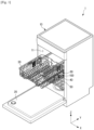
- FIG. 1 is a perspective view of a dish washer according to an embodiment of the disclosure.
- a dish washer 1 includes a case 10 having an opening 11 in the front side, a door 20 configured to close or open the opening of the case 10, a basket 30 accommodating dishes and configured to be put into or taken out of the case 10, a rail 40 configured to guide movements of the basket 30, and a basket roller 100 rotatably coupled with the basket 30 and configured to move along the rail 40.
- the dish washer 1 may close the door 20 and then wash dishes accommodated in the basket 30 with a detergent and water.
- the dish washer 1 may further include various components, such as a spray nozzle (not shown) for spraying water, which will be described in detail, later.
- the basket 30 When the basket 30 is taken out of or put into the case 10, the basket 30 may need to move smoothly.
- the basket roller 100 rested on the rail 40 needs to rotate smoothly.
- a burr is formed on the rolling surface of a roller and may interfere with smooth rotations of the roller.
- the burr is a kind of protrusion that is necessarily formed along a parting line upon injection-molding.
- the roller moves up and down due to the burr when rotating, which interferes with smooth rotations of the roller.
- a burr is necessarily formed. Therefore, the burr may need to be formed at an area other than the rolling surface of the roller.
- the roller according to an embodiment of the disclosure may be used in various home appliances or furniture using rails and rollers, as well as a dish washer.
- a dish washer will be described as an example.
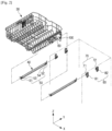
- FIG. 2 shows a basket, rails and rollers in a dish washer according to an embodiment of the disclosure.
- a bracket 60 may be installed on the basket 30.
- the basket roller 100 may be rotatably coupled with the bracket 60.
- the basket roller 100 may rotate on an outer surface of the rail 40 in contact with the outer surface of the rail 40.
- the basket 30 may move forward or backward with respect to the rail 40.
- a plurality of rail rollers 70 may be provided in the inside of the rail 40 in such a way to be rotatable with respect to the rail 40.
- the rail 40 may include a plurality of stoppers 50 including stoppers 51, 52, 53, and 54 positioned at both ends of the rail 40 to limit moving ranges of the basket roller 100 and the rail roller 70.
- the rail roller 70 may be fixed on an inner wall of the case 10 through a plurality of roller fixing members 80, including first roller fixing member 81 and second roller fixing member 82. Because the rail roller 70 is fixed on the inner wall of the case 10, movements of the rail roller 70 may be limited.
- the rail roller 70 may be rotatable on its rotation shaft, and when the rail roller 70 rotates, the rail 40 may move forward or backward, which will be described in detail, later.
- FIG. 3 is an enlarged view of a basket, a rail and rollers in a dish washer according to an embodiment of the disclosure.
- a plurality of basket rollers 100 may be coupled with the bracket 60.
- the basket rollers 100 may include two upper rollers 100a and 100c and a lower roller 100b. More specifically, the two upper rollers 100a and 100c and the lower roller 100b may be rotatably installed on the bracket 60.
- bracket rollers 100a to 100c When a rotation shaft 101 penetrates an insertion hole 140a (see FIGS. 4 to 6 ) of each of the basket rollers 100a to 100c to be coupled with the bracket 60, the bracket rollers 100a to 100c may be rotatably coupled with the bracket 60.
- the numbers of the upper rollers 100a and 100c and the lower roller 100b may change according to a design specification.
- the basket rollers 100a to 100c may be rotatably coupled directly with the basket 30, without a separate bracket.
- the upper rollers 100a and 100c and the lower roller 100b may have the same structure.
- the upper rollers 100a and 100c may be rested on the upper surface of the rail 40.
- the upper rollers 100a and 100c may move forward or backward along the upper surface of the rail 40.
- the lower roller 100b may be rested on a lower surface of the rail 40.
- the lower roller 100b may move forward or backward along the lower surface of the rail 40.
- the rail 40 may be positioned between the upper rollers 100a and 100c and the lower roller 100b. Because the rail 40 is positioned between the upper rollers 100a and 100c and the lower roller 100b, the rail 40 may be coupled with the basket 30. The upper rollers 100a and 100c may prevent the basket 30 from escaping downward from the rail 40. The lower roller 100b may prevent the basket 30 from escaping upward from the rail 40. That is, because the basket roller 100 includes the upper rollers 100a and 100c and the lower roller 100b, the basket roller 100 may prevent the basket 30 from being separated from the rail 40.
- the upper rollers 100a and 100c may rotate in contact with the upper surface of the rail 40, and the lower roller 100b may rotate in contact with the lower surface of the rail 40. Because the upper rollers 100a and 100c and the lower roller 100b are in contact with the upper and lower surfaces of the rail 40, up and down movements of the basket 30 may be reduced. Accordingly, the basket 30 may move forward or backward stably with respect to the rail 40.
- the bracket 60 may be coupled with the basket 30 through a connection bracket 61.
- the connection bracket 61 may be coupled with the basket 30, and the bracket 60 may be coupled with the connection bracket 61. That is, the connection bracket 61 may function as a medium for coupling the bracket 60 with the basket 30. However, the bracket 60 may be coupled directly with the basket 30.
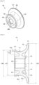
- FIG. 4 shows a roller according to an embodiment of the disclosure
- FIG. 5 shows the roller of FIG. 4 as seen at another angle
- FIG. 6 is a side cross-sectional view of the roller shown in FIG. 4 .
- the basket roller 100 includes a first flare portion 120 with a greater diameter at a longer distance in first direction from a predetermined location 110 of the basket roller 100, and a second flare portion 130 with a greater diameter at a longer distance in second direction from the predetermined location 110 of the basket roller 100.
- the second direction is opposite to the first direction.
- the predetermined location 110 may be a location at which the diameter of the basket roller 100 is a minimum.
- the predetermined location 110 corresponds to a rolling portion that rolls in contact with the rail 40.
- the predetermined location 110 will be referred to as a rolling portion.
- the rolling portion 110 may be a boundary between the first flare portion 120 and the second flare portion 130.
- the first flare portion 120 may prevent the basket roller 100 from escaping in the first direction from the rail 40.
- the first flare portion 120 may have a greater diameter at a longer distance from the rolling portion 110. More specifically, the diameter of the first flare portion 120 may be a minimum 110d at the rolling portion 110, and a maximum 120d at a first end of the basket roller 100.
- the second flare portion 130 may prevent the basket roller 100 from escaping in the second direction from the rail 40, wherein the second direction may be opposite to the first direction.
- the second flare portion 130 may have a greater diameter at a longer distance from the rolling portion 110. More specifically, the diameter of the second flare portion 130 may be the minimum 110d at the rolling portion 110, and a maximum 130d at a second end of the basket roller 100.
- the diameter 120d of the first flare portion 120 is greater than the diameter 130d of the second flare portion 130.
- the diameter 120d of the first flare portion 120 may be a maximum external diameter of the first flare portion 120
- the diameter 130d of the second flare portion 130 may be a maximum external diameter of the second flare portion 130.
- the basket roller 100 may have an asymmetrical shape. Because no burr is formed on the rolling portion 110 due to the asymmetrical shape of the basket roller 100, the basket roller 100 may rotate smoothly, which will be described in detail, later.
- the first flare portion 120 may also be referred to as a first wall.
- the second flare portion 130 may be referred to as a second wall.
- the first wall may be larger than the second wall.
- the first flare portion 120 and the second flare portion 130 may have curvatures.
- the expression “great curvature” refers to "great bending”.
- the curvature 120c of the first flare portion 120 may be greater than the curvature 130c of the second flare portion 130. At the same distance in an axial direction from the rolling portion 110, the diameter of the first flare portion 120 may be greater than that of the second flare portion 130.
- the basket roller 100 may further include a plurality of ribs 150 connecting the first flare portion 120 to a shaft coupler 140 to reinforce the strength of the first flare portion 120.
- the plurality of ribs 150 may be spaced apart from each other along a circumferential direction of the shaft coupler 140.
- a first recess, or groove, 144 may be formed between the first flare portion 120 and the shaft coupler 140.
- the first groove 144 may reduce the thickness of the first flare portion 120. Therefore, the first groove 144 may prevent the basket roller 100 from contracting during an injection-molding process. Also, the first groove 144 may help a mold move backward in the axial direction of the basket roller 100 when the basket roller 100 is manufactured. However, when the first groove 144 is provided, the thickness of the first flare portion 120 may become thin compared to a case in which the first groove 144 is not provided. As the thickness of the first flare portion 120 is thin, the strength of the first flare portion 120 may be weakened. Accordingly, the plurality of ribs 150 may be provided in the first groove 144 to reinforce the strength of the first flare portion 120. In FIG. 4 , eight ribs 150 are provided, however, the number of the ribs 150 may change according to a design specification.
- the basket roller 100 may include a second recess 143 recessed in the axial direction between the shaft coupler 140 and the second flare portion 130.
- a width in a radial direction of the second groove 143 may decrease as a depth in an axial direction of the second groove 143 increases.
- an inner surface of the second flare portion 130 forming a part of the second recess 143 may be inclined with respect to the axial direction. Because the inner surface of the second flare portion 130 is inclined with respect to the axial direction, a core may be easily taken out in the axial direction when the basket roller 100 is manufactured. Because the inner surface of the second flare portion 130 is inclined, the second flare portion 130 may have a substantially similar thickness, although the thickness of the second flare portion 130 changes gradually in the axial direction.
- the thickness of the second flare portion 130 may be smaller at a longer distance in an axial direction from the rolling portion 110, or may be uniform. Referring to FIG. 6 , the thickness of the second flare portion 130 may become a maximum thickness 131d at the rolling portion 110, and decrease gradually in the axial direction so as to become a minimum thickness 132d at the other end of the second flare portion 130. However, a difference between the maximum thickness 131d and the minimum thickness 132d of the second flare portion 130 may not be great. Accordingly, as described above, the second flare portion 130 may have a similar thickness along the axial direction. The thickness of the second flare portion 130 may be thin so that the second flare portion 130 has elasticity. For example, the thickness of the second flare portion 130 may be 3 mm or less.
- the stripping process is a process of forcibly stripping an injection-molding product from a mold by using the elasticity of the injection-molding product.
- the injection-molding product may be broken so that the stripping process can be not used.
- the basket roller 100 may include a burr 101.
- the basket roller 100 may be manufactured by injection-molding. Due to the characteristics of injection-molding, the basket roller 100 may necessarily include the burr 101. According to a technical idea of the disclosure, the burr 101 may be formed at another location except for the rolling surface of the basket roller 100.
- the bur 101 may be formed at an area of the first flare portion 120 at which the diameter of the first flare portion 120 is the maximum. That is, the burr 101 may be formed at the first end of the first flare portion 120.
- the burr 101 may be formed along the circumferential direction of the first flare portion 120.
- the basket roller 100 may include the rolling surface that rolls in contact with the rail 40.
- the rolling surface of the basket roller 100 may include the rolling portion 110, a part of the first flare portion 120, and a part of the second flare portion 130.
- the rolling surface of the basket roller 100 may occupy a predetermined area in both directions from the rolling portion 110, although it does not have an obvious boundary. Because an area of the first flare portion 120 whose diameter is the maximum is not in contact with the rail 40, the area of the first flare portion 120 may not be the rolling surface of the basket roller 100. Accordingly, when the burr 101 is formed in the area in which the diameter of the first flare portion 120 is the maximum, the burr 101 may be out of the rolling surface of the basket roller 100.
- the burr 101 which is a kind of protrusion
- the burr 101 may interfere with smooth rotations of the basket roller 100.
- the burr 101 may be located at an area which is not the rolling surface of the basket roller 100, and accordingly, the basket roller 100 may move smoothly on the rail 40.
- FIGS. 7 and 8 are views for comparing a typical roller with a roller according to an embodiment of the disclosure.
- a real rotation axis R1 of the basket roller 100 may be misaligned from an ideal rotation axis R of the basket roller 100.
- the real rotation axis R1 may be misaligned by ⁇ from the ideal rotation axis R according to a situation, wherein ⁇ may be an arbitrary angle.
- the basket roller 100 may reduce interference occurring between the basket roller 100 and the rail 40 compared to a typical basket roller, even when the real rotation axis R1 is misaligned from the ideal rotation axis R.
- the typical basket roller includes a pair of flare portions having the same height.
- a real rotation axis R1 of the typical basket roller is misaligned by ⁇ from an ideal rotation axis R of the typical basket roller
- the typical basket roller contacts a rail at two areas of a and b.
- the typical basket roller interferes with the rail at two flare portions having the same diameter. That is, interference between the typical basket roller and the rail occurs at all the areas of a and b, and accordingly, putting a basket into a case and taking the basket out of the case may be limited. Due to the interference of the basket roller with the rail, a great force may be required to rotate the basket roller or rotating the basket roller may be impossible.
- the basket roller 100 because the basket roller 100 according to an embodiment of the disclosure includes the second flare portion 130 having a smaller diameter than that of the first flare portion 120, no or little interference may occur between the basket roller 100 and the rail 40.
- the basket roller 100 includes the second flare portion 130, no interference may occur between the basket roller 100 and the rail 40.
- the first flare portion 120 of the basket roller 100 may interfere with the rail 40.
- the typical basket roller in which the second fare portion has the same diameter as that of the first flare portion may interfere with the rail 40 even at the area of A. Because the basket roller 100 according to an embodiment of the disclosure includes the second flare portion 130 having the smaller diameter than that of the first flare portion 120, interference between the basket roller 100 and the rail 40 may be reduced.
- the rail 40 may include an upper bending portion 41 bent at an upper end of the rail 40 and a lower bending portion 42 bent at a lower end of the rail 40.
- An opening 43 may be formed between the upper bending portion 41 and the lower bending portion 42. That is, the rail 40 may be a C-shaped rail.
- the upper bending portion 41 and the lower bending portion 42 may have the same curvature.
- a curvature 41c of the upper bending portion 41 and a curvature 42c of the lower bending portion 42 may be greater than a curvature 120c of the first flare portion 120.
- the basket roller 100 may move along an upper or lower surface of the rail 40.
- the rail roller 70 may be positioned in the inside of the rail 40 and move along an inner surface of the rail 40.
- the C-shaped rail may guide the rollers 100 and 70 on all of the inner and outer surfaces of the rail 40. Thereby, a distance to which the basket 30 is taken out may increase longer than a length of the rail 40.
- the real rotation axis R2 of the basket roller 100 may be misaligned by ⁇ from the ideal rotation axis R of the basket roller 100 due to an excessive or unbalanced load on the basket 30.
- the diameter of the second flare portion may be equal to the diameter of the first flare portion.
- the curvature of the first flare portion may be equal to the curvature of the second flare portion.
- excessive interference between the flare portion and the rail occurs to interfere with rotations of the basket roller, as shown in c and d of FIG. 8 . In this case, the flare portion may be broken due to the interference.
- the basket roller 100 includes the second flare portion 130, no excessive interference between the second flare portion 130 and the rail 40 may occur even when the real rotation axis R1 of the basket roller 100 is misaligned from the ideal rotation axis R of the basket roller 100.
- FIGS. 9 to 11 are views for describing an operation of taking a basket out in a dish washer according to an embodiment of the disclosure.
- the stoppers 51 to 54 may be positioned.
- the stoppers 51 to 54 may include a first basket stopper 51 and a second basket stopper 52. Also, the stoppers 51 to 54 may include a first rail stopper 53 and a second rail stopper 54.
- the first basket stopper 51 and the second basket stopper 52 may limit movements of the basket roller 100.
- the first rail stopper 53 and the second rail stopper 54 may limit movements of the rail 40.
- the first upper roller 100a may be limited in moving backward from the rail 40 by the second basket stopper 53.
- the first rail roller 71 may contact the first rail stopper 53, and the rail 40 may be limited in moving backward in the case 10.
- the basket roller 100 may first move forward with respect to the rail 40. Also, the bracket 60 and the basket 30 may move forward from the rail 40, together with the basket roller 100. At this time, the rail 40 may not move. As the basket 30 is taken out of the case 10, the first upper roller 100a may move away from the second basket stopper 52, and the second upper roller 100c may contact the first basket stopper 51.
- the second upper roller 100c may be limited in moving forward from the rail 40 by the first basket stopper 51.
- the rail roller 70 may rotate, and accordingly, the rail 40 may move forward.
- the basket 30 may be secondarily taken out of the case 10.
- the first rail roller 71 may move away from the first rail stopper 53, and the second rail roller 72 may contact the second rail stopper 54.
- the basket 30 may be no longer taken out.
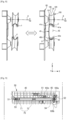
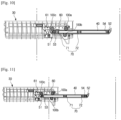
- FIG. 12 is a cross-sectional view of a first mold, a second mold, and a core, showing a state in which the first mold, the second mold, and the core are closed and a molten material is injected, in a method of manufacturing a roller according to an embodiment of the disclosure.
- FIG. 13 is a cross-sectional view of a first mold, a second mold, and a core, showing a state in which the first mold is separated from the second mold, in a method of manufacturing a roller according to an embodiment of the disclosure.
- FIG. 12 is a cross-sectional view of a first mold, a second mold, and a core, showing a state in which the first mold is separated from the second mold, in a method of manufacturing a roller according to an embodiment of the disclosure.
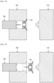
- FIG. 14 is a cross-sectional view of a first mold, a second mold, and a core, showing a state in which the core is separated from the second mold, in a method of manufacturing a roller according to an embodiment of the disclosure.
- FIG. 15 is a cross-sectional view of a first mold, a second mold, and a core, showing a state in which a roller as an injection-molding product is forcibly separated from the second mold, in a method of manufacturing a roller according to an embodiment of the disclosure.
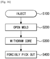
- FIG. 16 is a flowchart showing a method of manufacturing a roller according to an embodiment of the disclosure.
- the roller 100 may be manufactured by a stripping process.
- the stripping process may be a process of forcibly stripping an injection-molding product from a mold by using the elasticity of the injection-molding product.
- a molten material may be injected into an inside space, in operation S100.
- the inside space may be in the shape of the roller 100.
- the first mold 210 and the second mold 220 may form a parting line at an end of the roller 100. Because a burr is formed along the parting line, the burr may be formed at the end of the roller 100.
- the first mold 210 may be opened. At this time, the first mold 210 may be separated from the second mold 220 in a first direction that is parallel to the axial direction of the roller 100, in operation S200.
- the parting line may be formed on a plane that is orthogonal to a direction in which the first mold 210 is separated. According to a technical idea of the disclosure, the parting line may be formed at one end of the first flare portion 120.
- the core 230 may be separated in a second direction that is opposite to the first direction. That is, the core 230 may be withdrawn, in operation S300.
- the roller 100 as an injection-molding product may be forcibly picked out, in operation S400.
- a reason of forcibly picking the roller 100 out is because the second mold 220 interferes with the second flare portion 130 (see FIG. 6 ) when the roller 100 is picked out in the second direction.
- the second flare portion 130 may be broken during a process of forcibly picking the roller 100 out.
- the second flare portion 130 may be broken although the roller 100 has elasticity.
- the second flare portion 130 may have a height h (see FIG. 6 ) of 2mm or less.
Landscapes
- Engineering & Computer Science (AREA)
- Manufacturing & Machinery (AREA)
- Mechanical Engineering (AREA)
- Rolling Contact Bearings (AREA)
- Washing And Drying Of Tableware (AREA)
- Drawers Of Furniture (AREA)
Claims (13)
- Geschirrspülmaschine, umfassend:ein Gehäuse (10), das eine Öffnung (11) beinhaltet;einen Korb (30), der dazu konfiguriert ist, Geschirr aufzunehmen;eine Schiene (40), die im Gehäuse vorgesehen ist und dazu konfiguriert ist, den Korb zu führen, wenn der Korb auf der Schiene in das Gehäuse hinein oder aus diesem heraus gezogen wird; undeine Korbwalze (100), die mit dem Korb gekoppelt und dazu konfiguriert ist, sich relativ zum Korb zu drehen, um sich mit dem Korb entlang der Schiene zu bewegen, wenn der Korb auf der Schiene in das Gehäuse eingesetzt und aus diesem herausgenommen wird,wobei die Korbwalze (100) beinhaltet:einen Rollabschnitt (110) mit einer Oberfläche, die dazu konfiguriert ist, mit der Schiene in Kontakt zu stehen, wenn sich die Korbwalze dreht,einen ersten Aufweitungsabschnitt (120), der sich von einem ersten Ende des Rollabschnitts erstreckt und einen ersten äußeren Umfangsdurchmesser (120d) an einem Ende des ersten Aufweitungsabschnitts entfernt vom ersten Ende des Rollabschnitts aufweist, undeinen zweiten Aufweitungsabschnitt (130), der sich von einem zweiten Ende des Rollabschnitts erstreckt und einen zweiten äußeren Umfangsdurchmesser (130d) an einem Ende des zweiten Aufweitungsabschnitts entfernt vom zweiten Ende des Rollabschnitts aufweist, wobei das zweite Ende dem ersten Ende gegenüberliegt, unddadurch gekennzeichnet, dassder erste äußere Umfangsdurchmesser (120d) des ersten Aufweitungsabschnitts größer ist als der zweite äußere Umfangsdurchmesser (130d) des zweiten Aufweitungsabschnitts (130).
- Geschirrspülmaschine nach Anspruch 1, wobei ein äußerer Umfangsdurchmesser des ersten Aufweitungsabschnitts zunimmt, wenn ein Abstand entlang des ersten Aufweitungsabschnitts vom ersten Ende des Rollabschnitts zunimmt, und
ein äußerer Umfangsdurchmesser des zweiten Aufweitungsabschnitts zunimmt, wenn ein Abstand entlang des zweiten Aufweitungsabschnitts vom zweiten Ende des Rollabschnitts zunimmt. - Geschirrspülmaschine nach Anspruch 1, wobei der Rollabschnitt, der erste Aufweitungsabschnitt und der zweite Aufweitungsabschnitt einstückig als ein Körper geformt sind.
- Geschirrspülmaschine nach Anspruch 1, wobei ein Krümmungsradius (120c) des ersten Aufweitungsabschnitts kleiner ist als ein Krümmungsradius (130c) des zweiten Aufweitungsabschnitts.
- Geschirrspülmaschine nach Anspruch 1, wobei die Korbwalze ferner beinhaltet:einen Wellenkuppler (140), der dazu konfiguriert ist, eine Welle zum Koppeln mit dem Korb aufzunehmen;eine erste Aussparung (144), die zwischen dem ersten Aufweitungsabschnitt und dem Wellenkuppler vorgesehen ist; undeine zweite Aussparung (143), die zwischen dem zweiten Aufweitungsabschnitt und dem Wellenkuppler vorgesehen ist.
- Geschirrspülmaschine nach Anspruch 5, wobei die Korbwalze ferner eine Vielzahl von Rippen (150) beinhaltet, die den ersten Aufweitungsabschnitt mit dem Wellenkuppler (140) verbinden, um den ersten Aufweitungsabschnitt zu verstärken, wobei die Vielzahl von Rippen um einen Außenumfang des Wellenkupplers herum voneinander beabstandet sind.
- Geschirrspülmaschine nach Anspruch 1, wobei eine Dicke des zweiten Aufweitungsabschnitts abnimmt oder gleich bleibt, wenn ein Abstand entlang des zweiten Aufweitungsabschnitts vom zweiten Ende des Rollabschnitts zunimmt.
- Geschirrspülmaschine nach Anspruch 1, wobei die Korbwalze spritzgegossen ist.
- Geschirrspülmaschine nach Anspruch 5, wobei eine Innenfläche der zweiten Aussparung geneigt ist.
- Geschirrspülmaschine nach Anspruch 1, ferner umfassend eine Schienenwalze (70), die drehbar mit einer Innenwand des Gehäuses gekoppelt ist,
wobei die Schienenwalze zwischen einer oberen Oberfläche der Schiene und einer unteren Oberfläche der Schiene vorgesehen ist und dazu konfiguriert ist, sich relativ zum Gehäuse zu drehen, um die Schiene zu führen, wenn die Schiene in das Gehäuse geschoben und aus diesem herausgezogen wird, so dass der Korb in das Gehäuse eingesetzt und aus diesem herausgenommen wird. - Geschirrspülmaschine nach Anspruch 10, ferner umfassend einen ersten Anschlag (51) und einen zweiten Anschlag (52), die jeweils an einem ersten Ende und einem zweiten Ende der Schiene positioniert sind, und
wobei der erste Anschlag und der zweite Anschlag dazu konfiguriert sind, einen Bewegungsbereich der Korbwalze und der Schienenwalze zu begrenzen. - Geschirrspülmaschine nach Anspruch 11, wobei sich der Korb beim Herausnehmen aus dem Gehäuse zunächst bewegt, bis die Korbwalze den ersten Anschlag berührt, und sich dann bewegt, bis die Schienenwalze den zweiten Anschlag berührt.
- Verfahren zum Herstellen der Korbwalze (100) nach Anspruch 1, wobei das Verfahren umfasst:Schließen einer ersten Form (210), einer zweiten Form (220), die zusammen mit der ersten Form eine Trennlinie an einem Ende der Walze bildet, und eines Kerns (230);Einspritzen eines geschmolzenen Materials in einen Einspritzraum, der zwischen der ersten Form, der zweiten Form und dem Kern gebildet ist;Trennen der ersten Form von der zweiten Form in einer ersten Richtung, die parallel zu einer Drehachse der Walze ist, so dass ein Grat (101) entlang der äußeren Umfangsfläche des ersten Aufweitungsabschnitts an dem Ende des ersten Aufweitungsabschnitts entfernt vom ersten Ende des Rollabschnitts gebildet wird;Trennen des Kerns von der zweiten Form in einer zweiten Richtung, die der ersten Richtung entgegengesetzt ist; undgewaltsames Herausnehmen der Korbwalze als Spritzgussprodukt in der ersten Richtung aus der zweiten Form.
Applications Claiming Priority (2)
| Application Number | Priority Date | Filing Date | Title |
|---|---|---|---|
| KR1020180081373A KR102632053B1 (ko) | 2018-07-13 | 2018-07-13 | 롤러와 그 제조방법 및 롤러를 포함하는 식기세척기 |
| PCT/KR2019/008119 WO2020013512A1 (en) | 2018-07-13 | 2019-07-03 | Roller, method of manufacturing the same, and dish washer having the same |
Publications (4)
| Publication Number | Publication Date |
|---|---|
| EP3813628A4 EP3813628A4 (de) | 2021-05-05 |
| EP3813628A1 EP3813628A1 (de) | 2021-05-05 |
| EP3813628B1 true EP3813628B1 (de) | 2024-08-28 |
| EP3813628C0 EP3813628C0 (de) | 2024-08-28 |
Family
ID=69138904
Family Applications (1)
| Application Number | Title | Priority Date | Filing Date |
|---|---|---|---|
| EP19834582.9A Active EP3813628B1 (de) | 2018-07-13 | 2019-07-03 | Walze, verfahren zu ihrer herstellung und geschirrspülmaschine damit |
Country Status (5)
| Country | Link |
|---|---|
| US (1) | US11166619B2 (de) |
| EP (1) | EP3813628B1 (de) |
| KR (1) | KR102632053B1 (de) |
| CN (1) | CN112423641B (de) |
| WO (1) | WO2020013512A1 (de) |
Families Citing this family (4)
| Publication number | Priority date | Publication date | Assignee | Title |
|---|---|---|---|---|
| WO2020132823A1 (zh) * | 2018-12-24 | 2020-07-02 | 佛山市顺德区美的洗涤电器制造有限公司 | 滑动结构、碗篮及洗碗机 |
| KR102923825B1 (ko) * | 2020-05-19 | 2026-02-09 | (주)세고스 | 식기세척기용 레일장치 |
| USD1038714S1 (en) * | 2021-02-01 | 2024-08-13 | Electrolux Professional, Inc. | Collection basket |
| US12227330B2 (en) | 2021-02-01 | 2025-02-18 | Electrolux Professional, Inc. | Molded collection basket |
Family Cites Families (32)
| Publication number | Priority date | Publication date | Assignee | Title |
|---|---|---|---|---|
| US3672743A (en) * | 1970-08-17 | 1972-06-27 | W L Molding Co | Roller and retainer for a wire basket |
| US3736037A (en) * | 1971-06-01 | 1973-05-29 | Gen Electric | Rack level adjustment apparatus in an appliance cabinet |
| US3726581A (en) * | 1971-06-01 | 1973-04-10 | Gen Electric | Rack level adjustment apparatus in an appliance cabinet |
| US3785217A (en) * | 1972-07-17 | 1974-01-15 | Cons Foods Corp | Roller assembly and method of making the same |
| US3829191A (en) * | 1972-12-29 | 1974-08-13 | Gen Electric | Means for sealing a component supporting assembly in a washing appliance tub |
| US3851943A (en) * | 1972-12-29 | 1974-12-03 | Gen Electric | Rack support assembly in a dishwasher |
| US3982802A (en) * | 1975-11-03 | 1976-09-28 | General Motors Corporation | Dishwasher rack having retention means |
| DE3927214C2 (de) * | 1989-08-17 | 1995-09-07 | Miele & Cie | Frontseitig beschickbare Geschirrspülmaschine mit Geschirrkörben |
| US5165142A (en) * | 1990-10-04 | 1992-11-24 | Inventio Ag | Runner guide for a sliding elevator door |
| JP2596687B2 (ja) * | 1993-01-08 | 1997-04-02 | 株式会社神戸製鋼所 | 軽合金ホイールの製造方法 |
| US5474378A (en) * | 1993-12-03 | 1995-12-12 | Whirlpool Corporation | Adjustable support apparatus for a dishrack |
| DE4412775C2 (de) * | 1994-04-18 | 2002-06-27 | Friedrich Hachtel | Verfahren, spritzgegossene Laufrolle und Spritzgießform zur Herstellung einer Laufrolle, insbesondere für Schubauszüge von Geschirrspülmaschinen |
| DE19843277B4 (de) * | 1998-09-22 | 2007-06-14 | Friedrich Hachtel | Laufrolle aus Kunststoff und Verfahren zur Herstellung |
| KR100352071B1 (ko) * | 2000-08-28 | 2002-09-12 | 삼성전자 주식회사 | 저장고용 미끄럼장치 |
| DE10120577A1 (de) | 2001-04-26 | 2002-10-31 | Bsh Bosch Siemens Hausgeraete | Vorrichtung zum Verstellen der Höhenposition eines aus dem Spülbehälter einer Geschirrspülmaschine ausziehbaren Geschirrkorbs |
| DE10163875A1 (de) * | 2001-12-22 | 2003-07-10 | Aeg Hausgeraete Gmbh | Rollenführung für insbesondere schubladenartig herausfahrbare Behältnisse von Haushaltsgeräten |
| KR100457587B1 (ko) * | 2002-11-28 | 2004-11-17 | 엘지전자 주식회사 | 식기세척기의 선반 높이 조절장치 |
| KR100739563B1 (ko) * | 2003-08-20 | 2007-07-16 | 엘지전자 주식회사 | 식기세척기의 랙(rack) 높이 조절장치 |
| DE502005001274D1 (de) * | 2004-05-17 | 2007-10-04 | Steffen Hachtel | Rastbuchse mit Ausknüpfschutz |
| KR101154959B1 (ko) * | 2005-03-17 | 2012-06-18 | 엘지전자 주식회사 | 식기세척기의 식기 바스켓 레일 구조 |
| KR100798776B1 (ko) * | 2006-07-12 | 2008-01-29 | 삼성전자주식회사 | 식기바구니 높이 조절장치를 구비한 식기세척기 |
| JP4985001B2 (ja) * | 2007-03-19 | 2012-07-25 | パナソニック株式会社 | 換気装置 |
| US9131014B2 (en) | 2012-08-20 | 2015-09-08 | Cisco Technology, Inc. | Hitless pruning protocol upgrade on single supervisor network devices |
| DE202014001024U1 (de) * | 2014-02-06 | 2015-05-28 | Grass Gmbh | Vorrichtung zur Führung eines Auszugs und Möbel mit einer solchen Vorrichtung |
| CN204091913U (zh) * | 2014-09-28 | 2015-01-14 | 佛山市顺德区美的洗涤电器制造有限公司 | 碗篮滚轮及碗篮、洗碗机 |
| CN204504146U (zh) * | 2015-03-16 | 2015-07-29 | 江苏南山冶金机械制造有限公司 | 一种辊颈组合钢模 |
| US9579010B2 (en) * | 2015-06-11 | 2017-02-28 | Haier Us Appliance Solutions, Inc. | Dishwasher appliance |
| CN105266739B (zh) * | 2015-11-30 | 2018-06-12 | 佛山市顺德区美的洗涤电器制造有限公司 | 洗碗机喷臂装置 |
| CN205514453U (zh) * | 2015-11-30 | 2016-08-31 | 佛山市顺德区美的洗涤电器制造有限公司 | 洗碗机喷臂装置 |
| US10010239B2 (en) * | 2016-08-04 | 2018-07-03 | Whirlpool Corporation | Rack assembly for a dishwasher |
| DE102016217940A1 (de) * | 2016-09-20 | 2018-03-22 | BSH Hausgeräte GmbH | Haushaltsgeschirrspülmaschine |
| CN106424398B (zh) * | 2016-11-23 | 2018-07-17 | 中国人民解放军63926部队 | 一种大口径钢管喇叭口制作设备及方法 |
-
2018
- 2018-07-13 KR KR1020180081373A patent/KR102632053B1/ko active Active
-
2019
- 2019-07-03 CN CN201980046869.0A patent/CN112423641B/zh active Active
- 2019-07-03 WO PCT/KR2019/008119 patent/WO2020013512A1/en not_active Ceased
- 2019-07-03 EP EP19834582.9A patent/EP3813628B1/de active Active
- 2019-07-03 US US16/502,597 patent/US11166619B2/en active Active
Also Published As
| Publication number | Publication date |
|---|---|
| CN112423641A (zh) | 2021-02-26 |
| KR20200007352A (ko) | 2020-01-22 |
| US20200015654A1 (en) | 2020-01-16 |
| EP3813628A4 (de) | 2021-05-05 |
| EP3813628A1 (de) | 2021-05-05 |
| US11166619B2 (en) | 2021-11-09 |
| CN112423641B (zh) | 2024-11-01 |
| EP3813628C0 (de) | 2024-08-28 |
| KR102632053B1 (ko) | 2024-02-02 |
| WO2020013512A1 (en) | 2020-01-16 |
Similar Documents
| Publication | Publication Date | Title |
|---|---|---|
| EP3813628B1 (de) | Walze, verfahren zu ihrer herstellung und geschirrspülmaschine damit | |
| US5988007A (en) | Ball screw apparatus | |
| US9353471B2 (en) | Washing machine having balancer | |
| KR20170139801A (ko) | 식기 세척기 | |
| US11930986B2 (en) | Dishwasher | |
| EP3849391B1 (de) | Rollenvorrichtung und geschirrspülmaschine damit | |
| JP2021059186A (ja) | カップホルダ | |
| EP2332673B1 (de) | Lagergehäuse einer Waschmaschine | |
| KR20010107640A (ko) | 식기 세척기 | |
| KR100793412B1 (ko) | 회전 다각 코어 유니트 | |
| KR102581770B1 (ko) | 하중 지지용 롤러 유닛과 롤러 성형용 금형조립체 | |
| CN118065729A (zh) | 铰链组件、门组件及制冷设备 | |
| KR101839211B1 (ko) | 나선방향 작동 경사코어를 가지는 사출금형 | |
| KR101940516B1 (ko) | 모터와 이를 가지는 세탁기 | |
| KR101193474B1 (ko) | 세탁기용 도어의 힌지 장치 | |
| CA2395025C (en) | Method and apparatus for coupling a rack to a dishwasher | |
| CN220769182U (zh) | 铰链组件及家用电器 | |
| CN222796008U (zh) | 洗涤剂盒组件及衣物处理设备 | |
| KR101193262B1 (ko) | 식기 세척기 | |
| CN224149363U (zh) | 转动连接机构及可移动设备 | |
| CN104727676B (zh) | 一种重载锥形铰链 | |
| CN113662488B (zh) | 一种分配器和具有该分配器的洗碗机 | |
| CA2978901C (en) | Garage door hinge with noise reduction insert | |
| CN117365216A (zh) | 门体铰链和门中门冰箱 | |
| JP4840915B2 (ja) | ガイドローラ |
Legal Events
| Date | Code | Title | Description |
|---|---|---|---|
| STAA | Information on the status of an ep patent application or granted ep patent |
Free format text: STATUS: THE INTERNATIONAL PUBLICATION HAS BEEN MADE |
|
| PUAI | Public reference made under article 153(3) epc to a published international application that has entered the european phase |
Free format text: ORIGINAL CODE: 0009012 |
|
| STAA | Information on the status of an ep patent application or granted ep patent |
Free format text: STATUS: REQUEST FOR EXAMINATION WAS MADE |
|
| 17P | Request for examination filed |
Effective date: 20201126 |
|
| A4 | Supplementary search report drawn up and despatched |
Effective date: 20210325 |
|
| AK | Designated contracting states |
Kind code of ref document: A1 Designated state(s): AL AT BE BG CH CY CZ DE DK EE ES FI FR GB GR HR HU IE IS IT LI LT LU LV MC MK MT NL NO PL PT RO RS SE SI SK SM TR |
|
| DAV | Request for validation of the european patent (deleted) | ||
| DAX | Request for extension of the european patent (deleted) | ||
| GRAP | Despatch of communication of intention to grant a patent |
Free format text: ORIGINAL CODE: EPIDOSNIGR1 |
|
| STAA | Information on the status of an ep patent application or granted ep patent |
Free format text: STATUS: GRANT OF PATENT IS INTENDED |
|
| INTG | Intention to grant announced |
Effective date: 20240523 |
|
| GRAS | Grant fee paid |
Free format text: ORIGINAL CODE: EPIDOSNIGR3 |
|
| GRAA | (expected) grant |
Free format text: ORIGINAL CODE: 0009210 |
|
| STAA | Information on the status of an ep patent application or granted ep patent |
Free format text: STATUS: THE PATENT HAS BEEN GRANTED |
|
| AK | Designated contracting states |
Kind code of ref document: B1 Designated state(s): AL AT BE BG CH CY CZ DE DK EE ES FI FR GB GR HR HU IE IS IT LI LT LU LV MC MK MT NL NO PL PT RO RS SE SI SK SM TR |
|
| REG | Reference to a national code |
Ref country code: CH Ref legal event code: EP |
|
| REG | Reference to a national code |
Ref country code: DE Ref legal event code: R096 Ref document number: 602019058009 Country of ref document: DE |
|
| REG | Reference to a national code |
Ref country code: IE Ref legal event code: FG4D |
|
| U01 | Request for unitary effect filed |
Effective date: 20240917 |
|
| U07 | Unitary effect registered |
Designated state(s): AT BE BG DE DK EE FI FR IT LT LU LV MT NL PT RO SE SI Effective date: 20241009 |
|
| PG25 | Lapsed in a contracting state [announced via postgrant information from national office to epo] |
Ref country code: NO Free format text: LAPSE BECAUSE OF FAILURE TO SUBMIT A TRANSLATION OF THE DESCRIPTION OR TO PAY THE FEE WITHIN THE PRESCRIBED TIME-LIMIT Effective date: 20241128 |
|
| PG25 | Lapsed in a contracting state [announced via postgrant information from national office to epo] |
Ref country code: GR Free format text: LAPSE BECAUSE OF FAILURE TO SUBMIT A TRANSLATION OF THE DESCRIPTION OR TO PAY THE FEE WITHIN THE PRESCRIBED TIME-LIMIT Effective date: 20241129 Ref country code: PL Free format text: LAPSE BECAUSE OF FAILURE TO SUBMIT A TRANSLATION OF THE DESCRIPTION OR TO PAY THE FEE WITHIN THE PRESCRIBED TIME-LIMIT Effective date: 20240828 |
|
| PG25 | Lapsed in a contracting state [announced via postgrant information from national office to epo] |
Ref country code: IS Free format text: LAPSE BECAUSE OF FAILURE TO SUBMIT A TRANSLATION OF THE DESCRIPTION OR TO PAY THE FEE WITHIN THE PRESCRIBED TIME-LIMIT Effective date: 20241228 |
|
| PG25 | Lapsed in a contracting state [announced via postgrant information from national office to epo] |
Ref country code: HR Free format text: LAPSE BECAUSE OF FAILURE TO SUBMIT A TRANSLATION OF THE DESCRIPTION OR TO PAY THE FEE WITHIN THE PRESCRIBED TIME-LIMIT Effective date: 20240828 |
|
| PG25 | Lapsed in a contracting state [announced via postgrant information from national office to epo] |
Ref country code: ES Free format text: LAPSE BECAUSE OF FAILURE TO SUBMIT A TRANSLATION OF THE DESCRIPTION OR TO PAY THE FEE WITHIN THE PRESCRIBED TIME-LIMIT Effective date: 20240828 Ref country code: RS Free format text: LAPSE BECAUSE OF FAILURE TO SUBMIT A TRANSLATION OF THE DESCRIPTION OR TO PAY THE FEE WITHIN THE PRESCRIBED TIME-LIMIT Effective date: 20241128 |
|
| PG25 | Lapsed in a contracting state [announced via postgrant information from national office to epo] |
Ref country code: RS Free format text: LAPSE BECAUSE OF FAILURE TO SUBMIT A TRANSLATION OF THE DESCRIPTION OR TO PAY THE FEE WITHIN THE PRESCRIBED TIME-LIMIT Effective date: 20241128 Ref country code: PL Free format text: LAPSE BECAUSE OF FAILURE TO SUBMIT A TRANSLATION OF THE DESCRIPTION OR TO PAY THE FEE WITHIN THE PRESCRIBED TIME-LIMIT Effective date: 20240828 Ref country code: NO Free format text: LAPSE BECAUSE OF FAILURE TO SUBMIT A TRANSLATION OF THE DESCRIPTION OR TO PAY THE FEE WITHIN THE PRESCRIBED TIME-LIMIT Effective date: 20241128 Ref country code: IS Free format text: LAPSE BECAUSE OF FAILURE TO SUBMIT A TRANSLATION OF THE DESCRIPTION OR TO PAY THE FEE WITHIN THE PRESCRIBED TIME-LIMIT Effective date: 20241228 Ref country code: HR Free format text: LAPSE BECAUSE OF FAILURE TO SUBMIT A TRANSLATION OF THE DESCRIPTION OR TO PAY THE FEE WITHIN THE PRESCRIBED TIME-LIMIT Effective date: 20240828 Ref country code: GR Free format text: LAPSE BECAUSE OF FAILURE TO SUBMIT A TRANSLATION OF THE DESCRIPTION OR TO PAY THE FEE WITHIN THE PRESCRIBED TIME-LIMIT Effective date: 20241129 Ref country code: ES Free format text: LAPSE BECAUSE OF FAILURE TO SUBMIT A TRANSLATION OF THE DESCRIPTION OR TO PAY THE FEE WITHIN THE PRESCRIBED TIME-LIMIT Effective date: 20240828 |
|
| PG25 | Lapsed in a contracting state [announced via postgrant information from national office to epo] |
Ref country code: SM Free format text: LAPSE BECAUSE OF FAILURE TO SUBMIT A TRANSLATION OF THE DESCRIPTION OR TO PAY THE FEE WITHIN THE PRESCRIBED TIME-LIMIT Effective date: 20240828 |
|
| PG25 | Lapsed in a contracting state [announced via postgrant information from national office to epo] |
Ref country code: CZ Free format text: LAPSE BECAUSE OF FAILURE TO SUBMIT A TRANSLATION OF THE DESCRIPTION OR TO PAY THE FEE WITHIN THE PRESCRIBED TIME-LIMIT Effective date: 20240828 |
|
| PG25 | Lapsed in a contracting state [announced via postgrant information from national office to epo] |
Ref country code: SK Free format text: LAPSE BECAUSE OF FAILURE TO SUBMIT A TRANSLATION OF THE DESCRIPTION OR TO PAY THE FEE WITHIN THE PRESCRIBED TIME-LIMIT Effective date: 20240828 |
|
| PLBE | No opposition filed within time limit |
Free format text: ORIGINAL CODE: 0009261 |
|
| STAA | Information on the status of an ep patent application or granted ep patent |
Free format text: STATUS: NO OPPOSITION FILED WITHIN TIME LIMIT |
|
| 26N | No opposition filed |
Effective date: 20250530 |
|
| U20 | Renewal fee for the european patent with unitary effect paid |
Year of fee payment: 7 Effective date: 20250723 |
|
| REG | Reference to a national code |
Ref country code: CH Ref legal event code: H13 Free format text: ST27 STATUS EVENT CODE: U-0-0-H10-H13 (AS PROVIDED BY THE NATIONAL OFFICE) Effective date: 20260224 |
|
| GBPC | Gb: european patent ceased through non-payment of renewal fee |
Effective date: 20250703 |
|
| PG25 | Lapsed in a contracting state [announced via postgrant information from national office to epo] |
Ref country code: GB Free format text: LAPSE BECAUSE OF NON-PAYMENT OF DUE FEES Effective date: 20250703 |
|
| PG25 | Lapsed in a contracting state [announced via postgrant information from national office to epo] |
Ref country code: CH Free format text: LAPSE BECAUSE OF NON-PAYMENT OF DUE FEES Effective date: 20250731 |