EP3813628B1 - Roller, method of manufacturing the same, and dish washer having the same - Google Patents
Roller, method of manufacturing the same, and dish washer having the same Download PDFInfo
- Publication number
- EP3813628B1 EP3813628B1 EP19834582.9A EP19834582A EP3813628B1 EP 3813628 B1 EP3813628 B1 EP 3813628B1 EP 19834582 A EP19834582 A EP 19834582A EP 3813628 B1 EP3813628 B1 EP 3813628B1
- Authority
- EP
- European Patent Office
- Prior art keywords
- roller
- basket
- rail
- flare portion
- mold
- Prior art date
- Legal status (The legal status is an assumption and is not a legal conclusion. Google has not performed a legal analysis and makes no representation as to the accuracy of the status listed.)
- Active
Links
Images


Classifications
-
- A—HUMAN NECESSITIES
- A47—FURNITURE; DOMESTIC ARTICLES OR APPLIANCES; COFFEE MILLS; SPICE MILLS; SUCTION CLEANERS IN GENERAL
- A47L—DOMESTIC WASHING OR CLEANING; SUCTION CLEANERS IN GENERAL
- A47L15/00—Washing or rinsing machines for crockery or tableware
- A47L15/42—Details
- A47L15/50—Racks ; Baskets
- A47L15/507—Arrangements for extracting racks, e.g. roller supports
-
- A—HUMAN NECESSITIES
- A47—FURNITURE; DOMESTIC ARTICLES OR APPLIANCES; COFFEE MILLS; SPICE MILLS; SUCTION CLEANERS IN GENERAL
- A47L—DOMESTIC WASHING OR CLEANING; SUCTION CLEANERS IN GENERAL
- A47L15/00—Washing or rinsing machines for crockery or tableware
- A47L15/42—Details
- A47L15/50—Racks ; Baskets
- A47L15/501—Baskets, e.g. for conveyor-type, in-sink type or hood-type machines
-
- B—PERFORMING OPERATIONS; TRANSPORTING
- B29—WORKING OF PLASTICS; WORKING OF SUBSTANCES IN A PLASTIC STATE IN GENERAL
- B29C—SHAPING OR JOINING OF PLASTICS; SHAPING OF MATERIAL IN A PLASTIC STATE, NOT OTHERWISE PROVIDED FOR; AFTER-TREATMENT OF THE SHAPED PRODUCTS, e.g. REPAIRING
- B29C45/00—Injection moulding, i.e. forcing the required volume of moulding material through a nozzle into a closed mould; Apparatus therefor
- B29C45/0025—Preventing defects on the moulded article, e.g. weld lines, shrinkage marks
-
- B—PERFORMING OPERATIONS; TRANSPORTING
- B29—WORKING OF PLASTICS; WORKING OF SUBSTANCES IN A PLASTIC STATE IN GENERAL
- B29C—SHAPING OR JOINING OF PLASTICS; SHAPING OF MATERIAL IN A PLASTIC STATE, NOT OTHERWISE PROVIDED FOR; AFTER-TREATMENT OF THE SHAPED PRODUCTS, e.g. REPAIRING
- B29C45/00—Injection moulding, i.e. forcing the required volume of moulding material through a nozzle into a closed mould; Apparatus therefor
- B29C45/17—Component parts, details or accessories; Auxiliary operations
- B29C45/40—Removing or ejecting moulded articles
- B29C45/44—Removing or ejecting moulded articles for undercut articles
- B29C45/4407—Removing or ejecting moulded articles for undercut articles by flexible movement of undercut portions of the articles
-
- B—PERFORMING OPERATIONS; TRANSPORTING
- B29—WORKING OF PLASTICS; WORKING OF SUBSTANCES IN A PLASTIC STATE IN GENERAL
- B29C—SHAPING OR JOINING OF PLASTICS; SHAPING OF MATERIAL IN A PLASTIC STATE, NOT OTHERWISE PROVIDED FOR; AFTER-TREATMENT OF THE SHAPED PRODUCTS, e.g. REPAIRING
- B29C45/00—Injection moulding, i.e. forcing the required volume of moulding material through a nozzle into a closed mould; Apparatus therefor
- B29C45/0025—Preventing defects on the moulded article, e.g. weld lines, shrinkage marks
- B29C2045/0034—Mould parting lines
-
- B—PERFORMING OPERATIONS; TRANSPORTING
- B29—WORKING OF PLASTICS; WORKING OF SUBSTANCES IN A PLASTIC STATE IN GENERAL
- B29K—INDEXING SCHEME ASSOCIATED WITH SUBCLASSES B29B, B29C OR B29D, RELATING TO MOULDING MATERIALS OR TO MATERIALS FOR MOULDS, REINFORCEMENTS, FILLERS OR PREFORMED PARTS, e.g. INSERTS
- B29K2995/00—Properties of moulding materials, reinforcements, fillers, preformed parts or moulds
- B29K2995/0037—Other properties
- B29K2995/0046—Elastic
-
- B—PERFORMING OPERATIONS; TRANSPORTING
- B29—WORKING OF PLASTICS; WORKING OF SUBSTANCES IN A PLASTIC STATE IN GENERAL
- B29L—INDEXING SCHEME ASSOCIATED WITH SUBCLASS B29C, RELATING TO PARTICULAR ARTICLES
- B29L2031/00—Other particular articles
- B29L2031/32—Wheels, pinions, pulleys, castors or rollers, Rims
- B29L2031/322—Wheels, pinions, pulleys, castors or rollers, Rims made wholly of plastics
Definitions
- the disclosure relates to a roller, a method of manufacturing the same, and a dish washer having the roller.
- a dish washer is a machine for automatically washing off food residues, etc. on dishes with a detergent and water.
- a dish washer in general, includes a case having an opening in the front side, a door for opening or closing the opening of the case, a basket for accommodating dishes and configured to be taken out of or put into the case, and a spray nozzle for spraying water.
- the dish washer includes rails provided in the inside of the case and guiding the basket to be put into or taken out of the case, and rollers rotating along the rails and supporting movements of the basket.
- the rollers are integrated type rollers or combined type rollers.
- the combined type rollers are manufactured by combining two parts in the axial direction, and the integrated type rollers are manufactured by injection-molding.
- the combined type rollers have lower durability than the integrated type rollers.
- a burr formed by injection molding is positioned on the rolling surfaces. Because the burr is formed on the rolling surfaces of the rollers, the rollers move up and down due to the burr when rotating. That is, the burr interferes with smooth rotations of the rollers, and also prevents the basket from being smoothly put into or taken out of the case.
- the basket roller may include a burr, and the burr may be formed along a circumferential direction of the first flare portion.
- the diameter of the first flare portion may increase toward the first direction from the rolling portion, and the diameter of the second flare portion may increase toward the second direction from the rolling portion.
- the rolling portion, the first flare portion, and the second flare portion may be integrated into one body.
- the burr may be formed at one end of the first flare portion.
- the first flare portion and the second flare portion may have curvatures, respectively, and the curvature of the first flare portion may be greater than the curvature of the second flare portion.
- the basket roller may include: a shaft coupler in which a shaft of the basket roller is inserted; a first recess recessed in the second direction between the first flare portion and the shaft coupler; and a second recess recessed in the first direction between the second flare portion and the shaft coupler.
- the basket roller may further include a plurality of ribs connecting the first flare portion to the shaft coupler and functioning to reinforce strength of the first flare portion, the plurality of ribs being spaced from each other along a circumferential direction of the shaft coupler.
- a thickness of the second flare portion may be smaller at a longer distance in the second direction from the rolling portion, or the thickness of the second flare portion may be uniform.
- the basket roller may be manufactured by injection-molding.
- An inner surface of the second flare portion forming the second recess may be inclined with respect to the first direction.
- the dish washer may further include a rail roller rotatably coupled with an inner wall of the case, wherein the rail roller may be configured to rotate between an upper surface of the rail and a lower surface of the rail to move the rail.
- the dish washer may further include a first stopper and a second stopper respectively positioned at a first end and a second end of the rail, and the first stopper and the second stopper may be configured to limit movement ranges of the basket roller and the rail roller.
- the basket When the basket is taken out of the case, the basket first may move until the basket roller contacts the first stopper, and then move until the rail roller contacts the second stopper.
- the burr may be formed at one end of the first flare portion to be in non-contact with the rail when the roller moves along the rail.
- An upper surface or a lower surface of the rail may be curved to correspond to the rolling portion.
- a method of manufacturing a roller according to claim 1 includes: closing a first mold, a second mold forming a parting line at one end of the roller together with the first mold, and a core; injecting a molten material into an injection space formed between the first mold, the second mold, and the core; separating the first mold from the second mold in a first direction that is parallel to a rotation axis of the roller such that a burr is formed along a circumferential direction of the roller; separating the core from the second mold in a second direction that is opposite to the first direction; and forcibly picking out a roller as an injection-molding product in the first direction from the second mold.
- a roller indicates a basket roller.
- the basket roller may be a roller positioned on an outer surface of a rail and configured to move along an upper or lower surface of the rail.
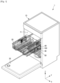
- FIG. 1 is a perspective view of a dish washer according to an embodiment of the disclosure.
- a dish washer 1 includes a case 10 having an opening 11 in the front side, a door 20 configured to close or open the opening of the case 10, a basket 30 accommodating dishes and configured to be put into or taken out of the case 10, a rail 40 configured to guide movements of the basket 30, and a basket roller 100 rotatably coupled with the basket 30 and configured to move along the rail 40.
- the dish washer 1 may close the door 20 and then wash dishes accommodated in the basket 30 with a detergent and water.
- the dish washer 1 may further include various components, such as a spray nozzle (not shown) for spraying water, which will be described in detail, later.
- the basket 30 When the basket 30 is taken out of or put into the case 10, the basket 30 may need to move smoothly.
- the basket roller 100 rested on the rail 40 needs to rotate smoothly.
- a burr is formed on the rolling surface of a roller and may interfere with smooth rotations of the roller.
- the burr is a kind of protrusion that is necessarily formed along a parting line upon injection-molding.
- the roller moves up and down due to the burr when rotating, which interferes with smooth rotations of the roller.
- a burr is necessarily formed. Therefore, the burr may need to be formed at an area other than the rolling surface of the roller.
- the roller according to an embodiment of the disclosure may be used in various home appliances or furniture using rails and rollers, as well as a dish washer.
- a dish washer will be described as an example.
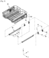
- FIG. 2 shows a basket, rails and rollers in a dish washer according to an embodiment of the disclosure.
- a bracket 60 may be installed on the basket 30.
- the basket roller 100 may be rotatably coupled with the bracket 60.
- the basket roller 100 may rotate on an outer surface of the rail 40 in contact with the outer surface of the rail 40.
- the basket 30 may move forward or backward with respect to the rail 40.
- a plurality of rail rollers 70 may be provided in the inside of the rail 40 in such a way to be rotatable with respect to the rail 40.
- the rail 40 may include a plurality of stoppers 50 including stoppers 51, 52, 53, and 54 positioned at both ends of the rail 40 to limit moving ranges of the basket roller 100 and the rail roller 70.
- the rail roller 70 may be fixed on an inner wall of the case 10 through a plurality of roller fixing members 80, including first roller fixing member 81 and second roller fixing member 82. Because the rail roller 70 is fixed on the inner wall of the case 10, movements of the rail roller 70 may be limited.
- the rail roller 70 may be rotatable on its rotation shaft, and when the rail roller 70 rotates, the rail 40 may move forward or backward, which will be described in detail, later.
- FIG. 3 is an enlarged view of a basket, a rail and rollers in a dish washer according to an embodiment of the disclosure.
- a plurality of basket rollers 100 may be coupled with the bracket 60.
- the basket rollers 100 may include two upper rollers 100a and 100c and a lower roller 100b. More specifically, the two upper rollers 100a and 100c and the lower roller 100b may be rotatably installed on the bracket 60.
- bracket rollers 100a to 100c When a rotation shaft 101 penetrates an insertion hole 140a (see FIGS. 4 to 6 ) of each of the basket rollers 100a to 100c to be coupled with the bracket 60, the bracket rollers 100a to 100c may be rotatably coupled with the bracket 60.
- the numbers of the upper rollers 100a and 100c and the lower roller 100b may change according to a design specification.
- the basket rollers 100a to 100c may be rotatably coupled directly with the basket 30, without a separate bracket.
- the upper rollers 100a and 100c and the lower roller 100b may have the same structure.
- the upper rollers 100a and 100c may be rested on the upper surface of the rail 40.
- the upper rollers 100a and 100c may move forward or backward along the upper surface of the rail 40.
- the lower roller 100b may be rested on a lower surface of the rail 40.
- the lower roller 100b may move forward or backward along the lower surface of the rail 40.
- the rail 40 may be positioned between the upper rollers 100a and 100c and the lower roller 100b. Because the rail 40 is positioned between the upper rollers 100a and 100c and the lower roller 100b, the rail 40 may be coupled with the basket 30. The upper rollers 100a and 100c may prevent the basket 30 from escaping downward from the rail 40. The lower roller 100b may prevent the basket 30 from escaping upward from the rail 40. That is, because the basket roller 100 includes the upper rollers 100a and 100c and the lower roller 100b, the basket roller 100 may prevent the basket 30 from being separated from the rail 40.
- the upper rollers 100a and 100c may rotate in contact with the upper surface of the rail 40, and the lower roller 100b may rotate in contact with the lower surface of the rail 40. Because the upper rollers 100a and 100c and the lower roller 100b are in contact with the upper and lower surfaces of the rail 40, up and down movements of the basket 30 may be reduced. Accordingly, the basket 30 may move forward or backward stably with respect to the rail 40.
- the bracket 60 may be coupled with the basket 30 through a connection bracket 61.
- the connection bracket 61 may be coupled with the basket 30, and the bracket 60 may be coupled with the connection bracket 61. That is, the connection bracket 61 may function as a medium for coupling the bracket 60 with the basket 30. However, the bracket 60 may be coupled directly with the basket 30.
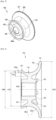
- FIG. 4 shows a roller according to an embodiment of the disclosure
- FIG. 5 shows the roller of FIG. 4 as seen at another angle
- FIG. 6 is a side cross-sectional view of the roller shown in FIG. 4 .
- the basket roller 100 includes a first flare portion 120 with a greater diameter at a longer distance in first direction from a predetermined location 110 of the basket roller 100, and a second flare portion 130 with a greater diameter at a longer distance in second direction from the predetermined location 110 of the basket roller 100.
- the second direction is opposite to the first direction.
- the predetermined location 110 may be a location at which the diameter of the basket roller 100 is a minimum.
- the predetermined location 110 corresponds to a rolling portion that rolls in contact with the rail 40.
- the predetermined location 110 will be referred to as a rolling portion.
- the rolling portion 110 may be a boundary between the first flare portion 120 and the second flare portion 130.
- the first flare portion 120 may prevent the basket roller 100 from escaping in the first direction from the rail 40.
- the first flare portion 120 may have a greater diameter at a longer distance from the rolling portion 110. More specifically, the diameter of the first flare portion 120 may be a minimum 110d at the rolling portion 110, and a maximum 120d at a first end of the basket roller 100.
- the second flare portion 130 may prevent the basket roller 100 from escaping in the second direction from the rail 40, wherein the second direction may be opposite to the first direction.
- the second flare portion 130 may have a greater diameter at a longer distance from the rolling portion 110. More specifically, the diameter of the second flare portion 130 may be the minimum 110d at the rolling portion 110, and a maximum 130d at a second end of the basket roller 100.
- the diameter 120d of the first flare portion 120 is greater than the diameter 130d of the second flare portion 130.
- the diameter 120d of the first flare portion 120 may be a maximum external diameter of the first flare portion 120
- the diameter 130d of the second flare portion 130 may be a maximum external diameter of the second flare portion 130.
- the basket roller 100 may have an asymmetrical shape. Because no burr is formed on the rolling portion 110 due to the asymmetrical shape of the basket roller 100, the basket roller 100 may rotate smoothly, which will be described in detail, later.
- the first flare portion 120 may also be referred to as a first wall.
- the second flare portion 130 may be referred to as a second wall.
- the first wall may be larger than the second wall.
- the first flare portion 120 and the second flare portion 130 may have curvatures.
- the expression “great curvature” refers to "great bending”.
- the curvature 120c of the first flare portion 120 may be greater than the curvature 130c of the second flare portion 130. At the same distance in an axial direction from the rolling portion 110, the diameter of the first flare portion 120 may be greater than that of the second flare portion 130.
- the basket roller 100 may further include a plurality of ribs 150 connecting the first flare portion 120 to a shaft coupler 140 to reinforce the strength of the first flare portion 120.
- the plurality of ribs 150 may be spaced apart from each other along a circumferential direction of the shaft coupler 140.
- a first recess, or groove, 144 may be formed between the first flare portion 120 and the shaft coupler 140.
- the first groove 144 may reduce the thickness of the first flare portion 120. Therefore, the first groove 144 may prevent the basket roller 100 from contracting during an injection-molding process. Also, the first groove 144 may help a mold move backward in the axial direction of the basket roller 100 when the basket roller 100 is manufactured. However, when the first groove 144 is provided, the thickness of the first flare portion 120 may become thin compared to a case in which the first groove 144 is not provided. As the thickness of the first flare portion 120 is thin, the strength of the first flare portion 120 may be weakened. Accordingly, the plurality of ribs 150 may be provided in the first groove 144 to reinforce the strength of the first flare portion 120. In FIG. 4 , eight ribs 150 are provided, however, the number of the ribs 150 may change according to a design specification.
- the basket roller 100 may include a second recess 143 recessed in the axial direction between the shaft coupler 140 and the second flare portion 130.
- a width in a radial direction of the second groove 143 may decrease as a depth in an axial direction of the second groove 143 increases.
- an inner surface of the second flare portion 130 forming a part of the second recess 143 may be inclined with respect to the axial direction. Because the inner surface of the second flare portion 130 is inclined with respect to the axial direction, a core may be easily taken out in the axial direction when the basket roller 100 is manufactured. Because the inner surface of the second flare portion 130 is inclined, the second flare portion 130 may have a substantially similar thickness, although the thickness of the second flare portion 130 changes gradually in the axial direction.
- the thickness of the second flare portion 130 may be smaller at a longer distance in an axial direction from the rolling portion 110, or may be uniform. Referring to FIG. 6 , the thickness of the second flare portion 130 may become a maximum thickness 131d at the rolling portion 110, and decrease gradually in the axial direction so as to become a minimum thickness 132d at the other end of the second flare portion 130. However, a difference between the maximum thickness 131d and the minimum thickness 132d of the second flare portion 130 may not be great. Accordingly, as described above, the second flare portion 130 may have a similar thickness along the axial direction. The thickness of the second flare portion 130 may be thin so that the second flare portion 130 has elasticity. For example, the thickness of the second flare portion 130 may be 3 mm or less.
- the stripping process is a process of forcibly stripping an injection-molding product from a mold by using the elasticity of the injection-molding product.
- the injection-molding product may be broken so that the stripping process can be not used.
- the basket roller 100 may include a burr 101.
- the basket roller 100 may be manufactured by injection-molding. Due to the characteristics of injection-molding, the basket roller 100 may necessarily include the burr 101. According to a technical idea of the disclosure, the burr 101 may be formed at another location except for the rolling surface of the basket roller 100.
- the bur 101 may be formed at an area of the first flare portion 120 at which the diameter of the first flare portion 120 is the maximum. That is, the burr 101 may be formed at the first end of the first flare portion 120.
- the burr 101 may be formed along the circumferential direction of the first flare portion 120.
- the basket roller 100 may include the rolling surface that rolls in contact with the rail 40.
- the rolling surface of the basket roller 100 may include the rolling portion 110, a part of the first flare portion 120, and a part of the second flare portion 130.
- the rolling surface of the basket roller 100 may occupy a predetermined area in both directions from the rolling portion 110, although it does not have an obvious boundary. Because an area of the first flare portion 120 whose diameter is the maximum is not in contact with the rail 40, the area of the first flare portion 120 may not be the rolling surface of the basket roller 100. Accordingly, when the burr 101 is formed in the area in which the diameter of the first flare portion 120 is the maximum, the burr 101 may be out of the rolling surface of the basket roller 100.
- the burr 101 which is a kind of protrusion
- the burr 101 may interfere with smooth rotations of the basket roller 100.
- the burr 101 may be located at an area which is not the rolling surface of the basket roller 100, and accordingly, the basket roller 100 may move smoothly on the rail 40.
- FIGS. 7 and 8 are views for comparing a typical roller with a roller according to an embodiment of the disclosure.
- a real rotation axis R1 of the basket roller 100 may be misaligned from an ideal rotation axis R of the basket roller 100.
- the real rotation axis R1 may be misaligned by ⁇ from the ideal rotation axis R according to a situation, wherein ⁇ may be an arbitrary angle.
- the basket roller 100 may reduce interference occurring between the basket roller 100 and the rail 40 compared to a typical basket roller, even when the real rotation axis R1 is misaligned from the ideal rotation axis R.
- the typical basket roller includes a pair of flare portions having the same height.
- a real rotation axis R1 of the typical basket roller is misaligned by ⁇ from an ideal rotation axis R of the typical basket roller
- the typical basket roller contacts a rail at two areas of a and b.
- the typical basket roller interferes with the rail at two flare portions having the same diameter. That is, interference between the typical basket roller and the rail occurs at all the areas of a and b, and accordingly, putting a basket into a case and taking the basket out of the case may be limited. Due to the interference of the basket roller with the rail, a great force may be required to rotate the basket roller or rotating the basket roller may be impossible.
- the basket roller 100 because the basket roller 100 according to an embodiment of the disclosure includes the second flare portion 130 having a smaller diameter than that of the first flare portion 120, no or little interference may occur between the basket roller 100 and the rail 40.
- the basket roller 100 includes the second flare portion 130, no interference may occur between the basket roller 100 and the rail 40.
- the first flare portion 120 of the basket roller 100 may interfere with the rail 40.
- the typical basket roller in which the second fare portion has the same diameter as that of the first flare portion may interfere with the rail 40 even at the area of A. Because the basket roller 100 according to an embodiment of the disclosure includes the second flare portion 130 having the smaller diameter than that of the first flare portion 120, interference between the basket roller 100 and the rail 40 may be reduced.
- the rail 40 may include an upper bending portion 41 bent at an upper end of the rail 40 and a lower bending portion 42 bent at a lower end of the rail 40.
- An opening 43 may be formed between the upper bending portion 41 and the lower bending portion 42. That is, the rail 40 may be a C-shaped rail.
- the upper bending portion 41 and the lower bending portion 42 may have the same curvature.
- a curvature 41c of the upper bending portion 41 and a curvature 42c of the lower bending portion 42 may be greater than a curvature 120c of the first flare portion 120.
- the basket roller 100 may move along an upper or lower surface of the rail 40.
- the rail roller 70 may be positioned in the inside of the rail 40 and move along an inner surface of the rail 40.
- the C-shaped rail may guide the rollers 100 and 70 on all of the inner and outer surfaces of the rail 40. Thereby, a distance to which the basket 30 is taken out may increase longer than a length of the rail 40.
- the real rotation axis R2 of the basket roller 100 may be misaligned by ⁇ from the ideal rotation axis R of the basket roller 100 due to an excessive or unbalanced load on the basket 30.
- the diameter of the second flare portion may be equal to the diameter of the first flare portion.
- the curvature of the first flare portion may be equal to the curvature of the second flare portion.
- excessive interference between the flare portion and the rail occurs to interfere with rotations of the basket roller, as shown in c and d of FIG. 8 . In this case, the flare portion may be broken due to the interference.
- the basket roller 100 includes the second flare portion 130, no excessive interference between the second flare portion 130 and the rail 40 may occur even when the real rotation axis R1 of the basket roller 100 is misaligned from the ideal rotation axis R of the basket roller 100.
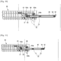
- FIGS. 9 to 11 are views for describing an operation of taking a basket out in a dish washer according to an embodiment of the disclosure.
- the stoppers 51 to 54 may be positioned.
- the stoppers 51 to 54 may include a first basket stopper 51 and a second basket stopper 52. Also, the stoppers 51 to 54 may include a first rail stopper 53 and a second rail stopper 54.
- the first basket stopper 51 and the second basket stopper 52 may limit movements of the basket roller 100.
- the first rail stopper 53 and the second rail stopper 54 may limit movements of the rail 40.
- the first upper roller 100a may be limited in moving backward from the rail 40 by the second basket stopper 53.
- the first rail roller 71 may contact the first rail stopper 53, and the rail 40 may be limited in moving backward in the case 10.
- the basket roller 100 may first move forward with respect to the rail 40. Also, the bracket 60 and the basket 30 may move forward from the rail 40, together with the basket roller 100. At this time, the rail 40 may not move. As the basket 30 is taken out of the case 10, the first upper roller 100a may move away from the second basket stopper 52, and the second upper roller 100c may contact the first basket stopper 51.
- the second upper roller 100c may be limited in moving forward from the rail 40 by the first basket stopper 51.
- the rail roller 70 may rotate, and accordingly, the rail 40 may move forward.
- the basket 30 may be secondarily taken out of the case 10.
- the first rail roller 71 may move away from the first rail stopper 53, and the second rail roller 72 may contact the second rail stopper 54.
- the basket 30 may be no longer taken out.
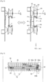
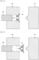
- FIG. 12 is a cross-sectional view of a first mold, a second mold, and a core, showing a state in which the first mold, the second mold, and the core are closed and a molten material is injected, in a method of manufacturing a roller according to an embodiment of the disclosure.
- FIG. 13 is a cross-sectional view of a first mold, a second mold, and a core, showing a state in which the first mold is separated from the second mold, in a method of manufacturing a roller according to an embodiment of the disclosure.
- FIG. 12 is a cross-sectional view of a first mold, a second mold, and a core, showing a state in which the first mold is separated from the second mold, in a method of manufacturing a roller according to an embodiment of the disclosure.
- FIG. 14 is a cross-sectional view of a first mold, a second mold, and a core, showing a state in which the core is separated from the second mold, in a method of manufacturing a roller according to an embodiment of the disclosure.
- FIG. 15 is a cross-sectional view of a first mold, a second mold, and a core, showing a state in which a roller as an injection-molding product is forcibly separated from the second mold, in a method of manufacturing a roller according to an embodiment of the disclosure.
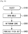
- FIG. 16 is a flowchart showing a method of manufacturing a roller according to an embodiment of the disclosure.
- the roller 100 may be manufactured by a stripping process.
- the stripping process may be a process of forcibly stripping an injection-molding product from a mold by using the elasticity of the injection-molding product.
- a molten material may be injected into an inside space, in operation S100.
- the inside space may be in the shape of the roller 100.
- the first mold 210 and the second mold 220 may form a parting line at an end of the roller 100. Because a burr is formed along the parting line, the burr may be formed at the end of the roller 100.
- the first mold 210 may be opened. At this time, the first mold 210 may be separated from the second mold 220 in a first direction that is parallel to the axial direction of the roller 100, in operation S200.
- the parting line may be formed on a plane that is orthogonal to a direction in which the first mold 210 is separated. According to a technical idea of the disclosure, the parting line may be formed at one end of the first flare portion 120.
- the core 230 may be separated in a second direction that is opposite to the first direction. That is, the core 230 may be withdrawn, in operation S300.
- the roller 100 as an injection-molding product may be forcibly picked out, in operation S400.
- a reason of forcibly picking the roller 100 out is because the second mold 220 interferes with the second flare portion 130 (see FIG. 6 ) when the roller 100 is picked out in the second direction.
- the second flare portion 130 may be broken during a process of forcibly picking the roller 100 out.
- the second flare portion 130 may be broken although the roller 100 has elasticity.
- the second flare portion 130 may have a height h (see FIG. 6 ) of 2mm or less.
Landscapes
- Engineering & Computer Science (AREA)
- Manufacturing & Machinery (AREA)
- Mechanical Engineering (AREA)
- Rolling Contact Bearings (AREA)
- Washing And Drying Of Tableware (AREA)
- Drawers Of Furniture (AREA)
Description
- The disclosure relates to a roller, a method of manufacturing the same, and a dish washer having the roller.
- A dish washer is a machine for automatically washing off food residues, etc. on dishes with a detergent and water.
- In general, a dish washer includes a case having an opening in the front side, a door for opening or closing the opening of the case, a basket for accommodating dishes and configured to be taken out of or put into the case, and a spray nozzle for spraying water.
- Also, the dish washer includes rails provided in the inside of the case and guiding the basket to be put into or taken out of the case, and rollers rotating along the rails and supporting movements of the basket.
- Generally, the rollers are integrated type rollers or combined type rollers. The combined type rollers are manufactured by combining two parts in the axial direction, and the integrated type rollers are manufactured by injection-molding.
- The combined type rollers have lower durability than the integrated type rollers.
- In the integrated type rollers, a burr formed by injection molding is positioned on the rolling surfaces. Because the burr is formed on the rolling surfaces of the rollers, the rollers move up and down due to the burr when rotating. That is, the burr interferes with smooth rotations of the rollers, and also prevents the basket from being smoothly put into or taken out of the case.
-
US2016/0360946A1 andUS3851943A disclose rack assemblies for dish washers. - It is an aspect of the disclosure to provide a roller capable of rotating smoothly without any burr on a rolling surface, a method of manufacturing the roller, and a dish washer including the roller.
- It is an aspect of the disclosure to provide a roller capable of rotating smoothly due to its asymmetrical structure even when an error is generated upon assembly of the roller, a method of manufacturing the roller, and a dish washer including the roller.
- In accordance with an aspect of the disclosure, there is provided a dish washer according to
claim 1. - Optional features are set out in the dependent claims.
- The basket roller may include a burr, and the burr may be formed along a circumferential direction of the first flare portion.
- The diameter of the first flare portion may increase toward the first direction from the rolling portion, and the diameter of the second flare portion may increase toward the second direction from the rolling portion.
- The rolling portion, the first flare portion, and the second flare portion may be integrated into one body.
- The burr may be formed at one end of the first flare portion.
- The first flare portion and the second flare portion may have curvatures, respectively, and the curvature of the first flare portion may be greater than the curvature of the second flare portion.
- The basket roller may include: a shaft coupler in which a shaft of the basket roller is inserted; a first recess recessed in the second direction between the first flare portion and the shaft coupler; and a second recess recessed in the first direction between the second flare portion and the shaft coupler.
- The basket roller may further include a plurality of ribs connecting the first flare portion to the shaft coupler and functioning to reinforce strength of the first flare portion, the plurality of ribs being spaced from each other along a circumferential direction of the shaft coupler.
- A thickness of the second flare portion may be smaller at a longer distance in the second direction from the rolling portion, or the thickness of the second flare portion may be uniform.
- The basket roller may be manufactured by injection-molding.
- An inner surface of the second flare portion forming the second recess may be inclined with respect to the first direction.
- The dish washer may further include a rail roller rotatably coupled with an inner wall of the case, wherein the rail roller may be configured to rotate between an upper surface of the rail and a lower surface of the rail to move the rail.
- The dish washer may further include a first stopper and a second stopper respectively positioned at a first end and a second end of the rail, and the first stopper and the second stopper may be configured to limit movement ranges of the basket roller and the rail roller.
- When the basket is taken out of the case, the basket first may move until the basket roller contacts the first stopper, and then move until the rail roller contacts the second stopper.
- The burr may be formed at one end of the first flare portion to be in non-contact with the rail when the roller moves along the rail.
- An upper surface or a lower surface of the rail may be curved to correspond to the rolling portion.
- A method of manufacturing a roller according to
claim 1 includes: closing a first mold, a second mold forming a parting line at one end of the roller together with the first mold, and a core; injecting a molten material into an injection space formed between the first mold, the second mold, and the core; separating the first mold from the second mold in a first direction that is parallel to a rotation axis of the roller such that a burr is formed along a circumferential direction of the roller; separating the core from the second mold in a second direction that is opposite to the first direction; and forcibly picking out a roller as an injection-molding product in the first direction from the second mold. - These and/or other aspects of the disclosure will become apparent and more readily appreciated from the following description of the embodiments, taken in conjunction with the accompanying drawings of which:
-
FIG. 1 is a perspective view of a dish washer according to an embodiment of the disclosure; -
FIG. 2 shows a basket, rails and rollers in a dish washer according to an embodiment of the disclosure; -
FIG. 3 is an enlarged view of a basket, a rail and rollers in a dish washer according to an embodiment of the disclosure; -
FIG. 4 shows a roller according to an embodiment of the disclosure; -
FIG. 5 shows the roller ofFIG. 4 as seen at another angle; -
FIG. 6 is a side cross-sectional view of the roller shown inFIG. 4 ; -
FIGS. 7 and8 are views for comparing a typical roller with a roller according to an embodiment of the disclosure; -
FIGS. 9 ,10, and 11 are views for describing an operation of taking a basket out of a dish washer according to an embodiment of the disclosure; -
FIG. 12 is a cross-sectional view of a first mold, a second mold, and a core, showing a state in which the first mold, the second mold, and the core are closed and a molten material is injected, in a method of manufacturing a roller according to an embodiment of the disclosure; -
FIG. 13 is a cross-sectional view of a first mold, a second mold, and a core, showing a state in which the first mold is separated from the second mold, in a method of manufacturing a roller according to an embodiment of the disclosure; -
FIG. 14 is a cross-sectional view of a first mold, a second mold, and a core, showing a state in which the core is separated from the second mold, in a method of manufacturing a roller according to an embodiment of the disclosure; -
FIG. 15 is a cross-sectional view of a first mold, a second mold, and a core, showing a state in which a roller as an injection-molding product is forcibly separated from the second mold, in a method of manufacturing a roller according to an embodiment of the disclosure; and -
FIG. 16 is a flowchart showing a method of manufacturing a roller according to an embodiment of the disclosure. - Reference will now be made in detail to the embodiments, examples of which are illustrated in the accompanying drawings, wherein like reference numerals refer to like elements throughout. The embodiments are described below to explain the disclosure by referring to the figures.
- Configurations illustrated in the embodiments and the drawings described in the present specification are only embodiments of the disclosure, and thus it is to be understood that various modifications may be made in these embodiments without departing from the scope of the invention, as defined by the claims.
- The terms used in the present specification are merely used to describe particular embodiments, and are not intended to limit the disclosure. It is to be understood that the singular forms "a," "an," and "the" include plural referents unless the context clearly dictates otherwise. It will be understood that when the terms "includes," "comprises," "including," and/or "comprising," when used in this specification, specify the presence of stated features, figures, steps, components, or combination thereof, but do not preclude the presence or addition of one or more other features, figures, steps, components, members, or combinations thereof.
- It will be understood that, although the terms "first," "second," etc. may be used herein to describe various components, these components should not be limited by these terms. These terms are only used to distinguish one component from another. For example, a first component could be termed a second component, and, similarly, a second component could be termed a first component, without departing from the scope of the disclosure.
- Hereinafter, the disclosure will be described in detail with reference to the accompanying drawings. Meanwhile, in the current specification, a roller indicates a basket roller. The basket roller may be a roller positioned on an outer surface of a rail and configured to move along an upper or lower surface of the rail.
-
FIG. 1 is a perspective view of a dish washer according to an embodiment of the disclosure. - As shown in
FIG. 1 , adish washer 1 includes acase 10 having anopening 11 in the front side, adoor 20 configured to close or open the opening of thecase 10, abasket 30 accommodating dishes and configured to be put into or taken out of thecase 10, arail 40 configured to guide movements of thebasket 30, and abasket roller 100 rotatably coupled with thebasket 30 and configured to move along therail 40. - The
dish washer 1 may close thedoor 20 and then wash dishes accommodated in thebasket 30 with a detergent and water. Thedish washer 1 may further include various components, such as a spray nozzle (not shown) for spraying water, which will be described in detail, later. - When the
basket 30 is taken out of or put into thecase 10, thebasket 30 may need to move smoothly. For this, thebasket roller 100 rested on therail 40 needs to rotate smoothly. - Typically, a burr is formed on the rolling surface of a roller and may interfere with smooth rotations of the roller. The burr is a kind of protrusion that is necessarily formed along a parting line upon injection-molding. When the burr is formed on the rolling surface of the roller, the roller moves up and down due to the burr when rotating, which interferes with smooth rotations of the roller. As described above, when a roller is manufactured by injection-molding, a burr is necessarily formed. Therefore, the burr may need to be formed at an area other than the rolling surface of the roller.
- The roller according to an embodiment of the disclosure may be used in various home appliances or furniture using rails and rollers, as well as a dish washer. Hereinafter, a dish washer will be described as an example.
-
FIG. 2 shows a basket, rails and rollers in a dish washer according to an embodiment of the disclosure. - As shown in
FIG. 2 , abracket 60 may be installed on thebasket 30. Thebasket roller 100 may be rotatably coupled with thebracket 60. Thebasket roller 100 may rotate on an outer surface of therail 40 in contact with the outer surface of therail 40. When thebasket roller 100 rotates, thebasket 30 may move forward or backward with respect to therail 40. - A plurality of
rail rollers 70, includingfirst rail roller 71 andsecond rail roller 72, may be provided in the inside of therail 40 in such a way to be rotatable with respect to therail 40. Therail 40 may include a plurality ofstoppers 50 includingstoppers rail 40 to limit moving ranges of thebasket roller 100 and therail roller 70. - The
rail roller 70 may be fixed on an inner wall of thecase 10 through a plurality ofroller fixing members 80, including firstroller fixing member 81 and secondroller fixing member 82. Because therail roller 70 is fixed on the inner wall of thecase 10, movements of therail roller 70 may be limited. Therail roller 70 may be rotatable on its rotation shaft, and when therail roller 70 rotates, therail 40 may move forward or backward, which will be described in detail, later. -
FIG. 3 is an enlarged view of a basket, a rail and rollers in a dish washer according to an embodiment of the disclosure. - As shown in
FIG. 3 , a plurality ofbasket rollers 100 may be coupled with thebracket 60. Thebasket rollers 100 may include twoupper rollers lower roller 100b. More specifically, the twoupper rollers lower roller 100b may be rotatably installed on thebracket 60. - When a
rotation shaft 101 penetrates aninsertion hole 140a (seeFIGS. 4 to 6 ) of each of thebasket rollers 100a to 100c to be coupled with thebracket 60, thebracket rollers 100a to 100c may be rotatably coupled with thebracket 60. The numbers of theupper rollers lower roller 100b may change according to a design specification. However, thebasket rollers 100a to 100c may be rotatably coupled directly with thebasket 30, without a separate bracket. Theupper rollers lower roller 100b may have the same structure. - The
upper rollers rail 40. Theupper rollers rail 40. - The
lower roller 100b may be rested on a lower surface of therail 40. Thelower roller 100b may move forward or backward along the lower surface of therail 40. - The
rail 40 may be positioned between theupper rollers lower roller 100b. Because therail 40 is positioned between theupper rollers lower roller 100b, therail 40 may be coupled with thebasket 30. Theupper rollers basket 30 from escaping downward from therail 40. Thelower roller 100b may prevent thebasket 30 from escaping upward from therail 40. That is, because thebasket roller 100 includes theupper rollers lower roller 100b, thebasket roller 100 may prevent thebasket 30 from being separated from therail 40. - The
upper rollers rail 40, and thelower roller 100b may rotate in contact with the lower surface of therail 40. Because theupper rollers lower roller 100b are in contact with the upper and lower surfaces of therail 40, up and down movements of thebasket 30 may be reduced. Accordingly, thebasket 30 may move forward or backward stably with respect to therail 40. Thebracket 60 may be coupled with thebasket 30 through aconnection bracket 61. Theconnection bracket 61 may be coupled with thebasket 30, and thebracket 60 may be coupled with theconnection bracket 61. That is, theconnection bracket 61 may function as a medium for coupling thebracket 60 with thebasket 30. However, thebracket 60 may be coupled directly with thebasket 30. -
FIG. 4 shows a roller according to an embodiment of the disclosure,FIG. 5 shows the roller ofFIG. 4 as seen at another angle, andFIG. 6 is a side cross-sectional view of the roller shown inFIG. 4 . - Hereinafter, a basket roller according to an embodiment of the disclosure will be described in detail with reference to
FIGS. 4 to 6 . - Referring to
FIGS. 4 to 6 , thebasket roller 100 includes afirst flare portion 120 with a greater diameter at a longer distance in first direction from apredetermined location 110 of thebasket roller 100, and asecond flare portion 130 with a greater diameter at a longer distance in second direction from thepredetermined location 110 of thebasket roller 100. The second direction is opposite to the first direction. Thepredetermined location 110 may be a location at which the diameter of thebasket roller 100 is a minimum. Thepredetermined location 110 corresponds to a rolling portion that rolls in contact with therail 40. Hereinafter, thepredetermined location 110 will be referred to as a rolling portion. - The rolling
portion 110 may be a boundary between thefirst flare portion 120 and thesecond flare portion 130. - The
first flare portion 120 may prevent thebasket roller 100 from escaping in the first direction from therail 40. Thefirst flare portion 120 may have a greater diameter at a longer distance from the rollingportion 110. More specifically, the diameter of thefirst flare portion 120 may be a minimum 110d at the rollingportion 110, and a maximum 120d at a first end of thebasket roller 100. - The
second flare portion 130 may prevent thebasket roller 100 from escaping in the second direction from therail 40, wherein the second direction may be opposite to the first direction. Thesecond flare portion 130 may have a greater diameter at a longer distance from the rollingportion 110. More specifically, the diameter of thesecond flare portion 130 may be the minimum 110d at the rollingportion 110, and a maximum 130d at a second end of thebasket roller 100. - The
diameter 120d of thefirst flare portion 120 is greater than thediameter 130d of thesecond flare portion 130. Thediameter 120d of thefirst flare portion 120 may be a maximum external diameter of thefirst flare portion 120, and thediameter 130d of thesecond flare portion 130 may be a maximum external diameter of thesecond flare portion 130. Thebasket roller 100 may have an asymmetrical shape. Because no burr is formed on the rollingportion 110 due to the asymmetrical shape of thebasket roller 100, thebasket roller 100 may rotate smoothly, which will be described in detail, later. - The
first flare portion 120 may also be referred to as a first wall. Likewise, thesecond flare portion 130 may be referred to as a second wall. The first wall may be larger than the second wall. - The
first flare portion 120 and thesecond flare portion 130 may have curvatures. In the following description, the expression "great curvature" refers to "great bending". - The
curvature 120c of thefirst flare portion 120 may be greater than thecurvature 130c of thesecond flare portion 130. At the same distance in an axial direction from the rollingportion 110, the diameter of thefirst flare portion 120 may be greater than that of thesecond flare portion 130. - The
basket roller 100 may further include a plurality ofribs 150 connecting thefirst flare portion 120 to ashaft coupler 140 to reinforce the strength of thefirst flare portion 120. The plurality ofribs 150 may be spaced apart from each other along a circumferential direction of theshaft coupler 140. - As shown in
FIG. 6 , a first recess, or groove, 144 may be formed between thefirst flare portion 120 and theshaft coupler 140. - Due to the characteristics of injection-molding, a thick injection-molding product may contract. The
first groove 144 may reduce the thickness of thefirst flare portion 120. Therefore, thefirst groove 144 may prevent thebasket roller 100 from contracting during an injection-molding process. Also, thefirst groove 144 may help a mold move backward in the axial direction of thebasket roller 100 when thebasket roller 100 is manufactured. However, when thefirst groove 144 is provided, the thickness of thefirst flare portion 120 may become thin compared to a case in which thefirst groove 144 is not provided. As the thickness of thefirst flare portion 120 is thin, the strength of thefirst flare portion 120 may be weakened. Accordingly, the plurality ofribs 150 may be provided in thefirst groove 144 to reinforce the strength of thefirst flare portion 120. InFIG. 4 , eightribs 150 are provided, however, the number of theribs 150 may change according to a design specification. - The
basket roller 100 may include asecond recess 143 recessed in the axial direction between theshaft coupler 140 and thesecond flare portion 130. A width in a radial direction of thesecond groove 143 may decrease as a depth in an axial direction of thesecond groove 143 increases. In other words, an inner surface of thesecond flare portion 130 forming a part of thesecond recess 143 may be inclined with respect to the axial direction. Because the inner surface of thesecond flare portion 130 is inclined with respect to the axial direction, a core may be easily taken out in the axial direction when thebasket roller 100 is manufactured. Because the inner surface of thesecond flare portion 130 is inclined, thesecond flare portion 130 may have a substantially similar thickness, although the thickness of thesecond flare portion 130 changes gradually in the axial direction. - The thickness of the
second flare portion 130 may be smaller at a longer distance in an axial direction from the rollingportion 110, or may be uniform. Referring toFIG. 6 , the thickness of thesecond flare portion 130 may become amaximum thickness 131d at the rollingportion 110, and decrease gradually in the axial direction so as to become aminimum thickness 132d at the other end of thesecond flare portion 130. However, a difference between themaximum thickness 131d and theminimum thickness 132d of thesecond flare portion 130 may not be great. Accordingly, as described above, thesecond flare portion 130 may have a similar thickness along the axial direction. The thickness of thesecond flare portion 130 may be thin so that thesecond flare portion 130 has elasticity. For example, the thickness of thesecond flare portion 130 may be 3 mm or less. When the thickness of thesecond flare portion 130 is thick, the elasticity of thesecond flare portion 130 may deteriorate, and a stripping process may not be used upon manufacturing thebasket roller 100. The stripping process is a process of forcibly stripping an injection-molding product from a mold by using the elasticity of the injection-molding product. When the elasticity of an injection-molding product is insufficient, the injection-molding product may be broken so that the stripping process can be not used. - The
basket roller 100 may include aburr 101. Thebasket roller 100 may be manufactured by injection-molding. Due to the characteristics of injection-molding, thebasket roller 100 may necessarily include theburr 101. According to a technical idea of the disclosure, theburr 101 may be formed at another location except for the rolling surface of thebasket roller 100. Thebur 101 may be formed at an area of thefirst flare portion 120 at which the diameter of thefirst flare portion 120 is the maximum. That is, theburr 101 may be formed at the first end of thefirst flare portion 120. Theburr 101 may be formed along the circumferential direction of thefirst flare portion 120. - The
basket roller 100 may include the rolling surface that rolls in contact with therail 40. The rolling surface of thebasket roller 100 may include the rollingportion 110, a part of thefirst flare portion 120, and a part of thesecond flare portion 130. The rolling surface of thebasket roller 100 may occupy a predetermined area in both directions from the rollingportion 110, although it does not have an obvious boundary. Because an area of thefirst flare portion 120 whose diameter is the maximum is not in contact with therail 40, the area of thefirst flare portion 120 may not be the rolling surface of thebasket roller 100. Accordingly, when theburr 101 is formed in the area in which the diameter of thefirst flare portion 120 is the maximum, theburr 101 may be out of the rolling surface of thebasket roller 100. When theburr 101, which is a kind of protrusion, is located on the rolling surface of thebasket roller 100, theburr 101 may interfere with smooth rotations of thebasket roller 100. According to a technical idea of the disclosure, theburr 101 may be located at an area which is not the rolling surface of thebasket roller 100, and accordingly, thebasket roller 100 may move smoothly on therail 40. -
FIGS. 7 and8 are views for comparing a typical roller with a roller according to an embodiment of the disclosure. - Referring to
FIGS. 7 and8 , when a load on thebasket 30 increases or when a load on thebasket 30 is biased, a real rotation axis R1 of thebasket roller 100 may be misaligned from an ideal rotation axis R of thebasket roller 100. - As shown in
FIG. 7 , the real rotation axis R1 may be misaligned by α from the ideal rotation axis R according to a situation, wherein α may be an arbitrary angle. - The
basket roller 100 according to an embodiment of the disclosure may reduce interference occurring between thebasket roller 100 and therail 40 compared to a typical basket roller, even when the real rotation axis R1 is misaligned from the ideal rotation axis R. - Referring to
FIG. 7 , the typical basket roller includes a pair of flare portions having the same height. When a real rotation axis R1 of the typical basket roller is misaligned by α from an ideal rotation axis R of the typical basket roller, the typical basket roller contacts a rail at two areas of a and b. In other words, the typical basket roller interferes with the rail at two flare portions having the same diameter. That is, interference between the typical basket roller and the rail occurs at all the areas of a and b, and accordingly, putting a basket into a case and taking the basket out of the case may be limited. Due to the interference of the basket roller with the rail, a great force may be required to rotate the basket roller or rotating the basket roller may be impossible. - Referring to A and B of
FIG. 7 , because thebasket roller 100 according to an embodiment of the disclosure includes thesecond flare portion 130 having a smaller diameter than that of thefirst flare portion 120, no or little interference may occur between thebasket roller 100 and therail 40. - More specifically, referring to A of
FIG. 7 , because thebasket roller 100 includes thesecond flare portion 130, no interference may occur between thebasket roller 100 and therail 40. Referring to B ofFIG. 7 , thefirst flare portion 120 of thebasket roller 100 may interfere with therail 40. The typical basket roller in which the second fare portion has the same diameter as that of the first flare portion may interfere with therail 40 even at the area of A. Because thebasket roller 100 according to an embodiment of the disclosure includes thesecond flare portion 130 having the smaller diameter than that of thefirst flare portion 120, interference between thebasket roller 100 and therail 40 may be reduced. - Referring to
FIG. 8 , therail 40 may include an upper bending portion 41 bent at an upper end of therail 40 and alower bending portion 42 bent at a lower end of therail 40. Anopening 43 may be formed between the upper bending portion 41 and thelower bending portion 42. That is, therail 40 may be a C-shaped rail. The upper bending portion 41 and thelower bending portion 42 may have the same curvature. Acurvature 41c of the upper bending portion 41 and acurvature 42c of thelower bending portion 42 may be greater than acurvature 120c of thefirst flare portion 120. - As described above, because the
rail 40 is a C-shaped rail, thebasket roller 100 may move along an upper or lower surface of therail 40. Also, therail roller 70 may be positioned in the inside of therail 40 and move along an inner surface of therail 40. The C-shaped rail may guide therollers rail 40. Thereby, a distance to which thebasket 30 is taken out may increase longer than a length of therail 40. - As shown in
FIG. 8 , the real rotation axis R2 of thebasket roller 100 may be misaligned by β from the ideal rotation axis R of thebasket roller 100 due to an excessive or unbalanced load on thebasket 30. - Referring to C of
FIG. 8 , because the curvature of the upper bending portion 41 is greater than the curvature of thefirst flare portion 120, no excessive friction power may be generated between thebasket roller 100 and the upper bending portion 41 even when the real rotation axis R2 of thebasket roller 100 may be misaligned from the ideal rotation axis R of thebasket roller 100. - Referring to D of
FIG. 8 , because the maximum diameter of thesecond flare portion 130 is smaller than the maximum diameter of thefirst flare portion 120, neither excessive friction nor interference may be generated between thesecond flare portion 130 and therail 40 even when the real rotation axis R1 of thebasket roller 100 is misaligned from the ideal rotation axis R of thebasket roller 100. - Referring to c and d of
FIG. 8 , in the typical basket roller, the diameter of the second flare portion may be equal to the diameter of the first flare portion. Also, in the typical basket roller, the curvature of the first flare portion may be equal to the curvature of the second flare portion. Also, in the typical basket roller, excessive interference between the flare portion and the rail occurs to interfere with rotations of the basket roller, as shown in c and d ofFIG. 8 . In this case, the flare portion may be broken due to the interference. - Meanwhile, because the
basket roller 100 according to an embodiment of the disclosure includes thesecond flare portion 130, no excessive interference between thesecond flare portion 130 and therail 40 may occur even when the real rotation axis R1 of thebasket roller 100 is misaligned from the ideal rotation axis R of thebasket roller 100. -
FIGS. 9 to 11 are views for describing an operation of taking a basket out in a dish washer according to an embodiment of the disclosure. - Hereinafter, an operation of taking the
basket 30 out by using therail roller 70, thebasket roller 100, therail 40, and thestoppers 51 to 54 will be described in detail. - At both ends of the
rail 40, thestoppers 51 to 54 may be positioned. - The
stoppers 51 to 54 may include afirst basket stopper 51 and asecond basket stopper 52. Also, thestoppers 51 to 54 may include afirst rail stopper 53 and asecond rail stopper 54. - The
first basket stopper 51 and thesecond basket stopper 52 may limit movements of thebasket roller 100. - The
first rail stopper 53 and thesecond rail stopper 54 may limit movements of therail 40. - Referring to
FIG. 9 , when thebasket 30 is put into thecase 10, the firstupper roller 100a may be limited in moving backward from therail 40 by thesecond basket stopper 53. At this time, thefirst rail roller 71 may contact thefirst rail stopper 53, and therail 40 may be limited in moving backward in thecase 10. - Referring to
FIG. 10 , when thebasket 30 is taken out of thecase 10, thebasket roller 100 may first move forward with respect to therail 40. Also, thebracket 60 and thebasket 30 may move forward from therail 40, together with thebasket roller 100. At this time, therail 40 may not move. As thebasket 30 is taken out of thecase 10, the firstupper roller 100a may move away from thesecond basket stopper 52, and the secondupper roller 100c may contact thefirst basket stopper 51. - Referring to
FIG. 11 , the secondupper roller 100c may be limited in moving forward from therail 40 by thefirst basket stopper 51. When thebasket 30 continues to be taken out of thecase 10, therail roller 70 may rotate, and accordingly, therail 40 may move forward. As therail 40 moves forward, thebasket 30 may be secondarily taken out of thecase 10. As thebasket 30 is taken out of thecase 10, thefirst rail roller 71 may move away from thefirst rail stopper 53, and thesecond rail roller 72 may contact thesecond rail stopper 54. When thesecond rail roller 72 contacts thesecond rail stopper 54, thebasket 30 may be no longer taken out. -
FIG. 12 is a cross-sectional view of a first mold, a second mold, and a core, showing a state in which the first mold, the second mold, and the core are closed and a molten material is injected, in a method of manufacturing a roller according to an embodiment of the disclosure.FIG. 13 is a cross-sectional view of a first mold, a second mold, and a core, showing a state in which the first mold is separated from the second mold, in a method of manufacturing a roller according to an embodiment of the disclosure.FIG. 14 is a cross-sectional view of a first mold, a second mold, and a core, showing a state in which the core is separated from the second mold, in a method of manufacturing a roller according to an embodiment of the disclosure.FIG. 15 is a cross-sectional view of a first mold, a second mold, and a core, showing a state in which a roller as an injection-molding product is forcibly separated from the second mold, in a method of manufacturing a roller according to an embodiment of the disclosure.FIG. 16 is a flowchart showing a method of manufacturing a roller according to an embodiment of the disclosure. - Hereinafter, a method of manufacturing a roller according to an embodiment of the disclosure will be described.
- The
roller 100 may be manufactured by injection-molding. Due to the characteristics of injection-molding, a burr may be formed along a parting line of theroller 100. According to a technical idea of the disclosure, the parting line of theroller 100 may be formed along the circumference of theroller 100. Accordingly, by adjusting the parting line of theroller 100, no burr may be located on the rolling surface of theroller 100. - According to the method of manufacturing the roller according to an embodiment of the disclosure, the
roller 100 may be manufactured by a stripping process. The stripping process may be a process of forcibly stripping an injection-molding product from a mold by using the elasticity of the injection-molding product. - Referring to
FIG. 12 , after afirst mold 210, asecond mold 220, and acore 230 are closed, a molten material may be injected into an inside space, in operation S100. - The inside space may be in the shape of the
roller 100. Thefirst mold 210 and thesecond mold 220 may form a parting line at an end of theroller 100. Because a burr is formed along the parting line, the burr may be formed at the end of theroller 100. - After a packing process and a cooling process are performed, the
first mold 210 may be opened. At this time, thefirst mold 210 may be separated from thesecond mold 220 in a first direction that is parallel to the axial direction of theroller 100, in operation S200. - The parting line may be formed on a plane that is orthogonal to a direction in which the
first mold 210 is separated. According to a technical idea of the disclosure, the parting line may be formed at one end of thefirst flare portion 120. - After the
first mold 210 is separated from thesecond mold 220, thecore 230 may be separated in a second direction that is opposite to the first direction. That is, thecore 230 may be withdrawn, in operation S300. - Finally, the
roller 100 as an injection-molding product may be forcibly picked out, in operation S400. A reason of forcibly picking theroller 100 out is because thesecond mold 220 interferes with the second flare portion 130 (seeFIG. 6 ) when theroller 100 is picked out in the second direction. When theroller 100 has no elasticity, thesecond flare portion 130 may be broken during a process of forcibly picking theroller 100 out. Also, when the diameter of thesecond flare portion 130 is too great or thesecond recess 143 is not provided, thesecond flare portion 130 may be broken although theroller 100 has elasticity. To prevent thesecond flare portion 130 from being broken when theroller 100 is forcibly picked out, thesecond flare portion 130 may have a height h (seeFIG. 6 ) of 2mm or less.
Claims (13)
- A dish washer comprising:a case (10) including an opening (11);a basket (30) configured to accommodate dishes;a rail (40) provided in the case and configured to guide the basket when the basket is drawn into or out of the case on the rail; anda basket roller (100) coupled to the basket and configured to rotate relative to the basket to move with the basket along the rail when the basket is put into and taken out of the case on the rail,wherein the basket roller (100) includes:the first outer circumferential diameter (120d) of the first flare portion is greater than the second outer circumferential diameter (130d) of the second flare portion (130).a rolling portion (110) having a surface configured to be in contact with the rail when the basket roller rotates,a first flare portion (120) extending from a first end of the rolling portion and having a first outer circumferential diameter (120d) at an end of the first flare portion away from the first end of the rolling portion, anda second flare portion (130) extending from a second end of the rolling portion and having a second outer circumferential diameter (130d) at an end of the second flare portion away from the second end of the rolling portion, the second end being opposite to the first end, and characterized in that
- The dish washer according to claim 1, wherein an outer circumferential diameter of the first flare portion increases as a distance along the first flare portion from the first end of the rolling portion increases, and
an outer circumferential diameter of the second flare portion increases as a distance along the second flare portion from the second end of the rolling portion increases. - The dish washer according to claim 1, wherein the rolling portion, the first flare portion, and the second flare portion are integrally formed as one body.
- The dish washer according to claim 1, wherein a radius of curvature (120c) of the first flare portion is less than a radius of curvature (1300) of the second flare portion.
- The dish washer according to claim 1, wherein the basket roller further includes:a shaft coupler (140) configured to receive a shaft to couple to the basket;a first recess (144) provided between the first flare portion and the shaft coupler; anda second recess (143) provided between the second flare portion and the shaft coupler.
- The dish washer according to claim 5, wherein the basket roller further includes a plurality of ribs (150) connecting the first flare portion to the shaft coupler (140) to reinforce the first flare portion, the plurality of ribs being spaced apart from each other around an outer circumference of the shaft coupler.
- The dish washer according to claim 1, wherein a thickness of the second flare portion decreases or remains uniform as a distance along the second flare portion from the second end of the rolling portion increases.
- The dish washer according to claim 1, wherein the basket roller is injection-molded.
- The dish washer according to claim 5, wherein an inner surface of the second recess is inclined.
- The dish washer according to claim 1, further comprising a rail roller (70) rotatably coupled to an inner wall of the case,
wherein the rail roller is provided between an upper surface of the rail and a lower surface of the rail and configured to rotate relative to the case to guide the rail when the rail is pushed into and pulled out of the case so that the basket is put into and taken out of the case. - The dish washer according to claim 10, further comprising a first stopper (51) and a second stopper (52) respectively positioned at a first end and a second end of the rail, and
the first stopper and the second stopper are configured to limit a range of movement by the basket roller and the rail roller. - The dish washer according to claim 11, wherein when the basket is taken out of the case, the basket first moves until the basket roller contacts the first stopper, and then moves until the rail roller contacts the second stopper.
- A method of manufacturing the basket roller (100) of claim 1, the method comprising:closing a first mold (210), a second mold (220) forming a parting line at one end of the roller together with the first mold, and a core (230);injecting a molten material into an injection space formed between the first mold, the second mold, and the core;separating the first mold from the second mold in a first direction that is parallel to a rotation axis of the roller such that a burr (101) is formed along the outer circumferential surface of the first flare portion at the end of the first flare portion away from the first end of the rolling portion;separating the core from the second mold in a second direction that is opposite to the first direction; andforcibly picking out the basket roller as an injection-molded product in the first direction from the second mold.
Applications Claiming Priority (2)
| Application Number | Priority Date | Filing Date | Title |
|---|---|---|---|
| KR1020180081373A KR102632053B1 (en) | 2018-07-13 | 2018-07-13 | Roller, method of mauufacturing the same and a dish washer having the same |
| PCT/KR2019/008119 WO2020013512A1 (en) | 2018-07-13 | 2019-07-03 | Roller, method of manufacturing the same, and dish washer having the same |
Publications (4)
| Publication Number | Publication Date |
|---|---|
| EP3813628A1 EP3813628A1 (en) | 2021-05-05 |
| EP3813628A4 EP3813628A4 (en) | 2021-05-05 |
| EP3813628B1 true EP3813628B1 (en) | 2024-08-28 |
| EP3813628C0 EP3813628C0 (en) | 2024-08-28 |
Family
ID=69138904
Family Applications (1)
| Application Number | Title | Priority Date | Filing Date |
|---|---|---|---|
| EP19834582.9A Active EP3813628B1 (en) | 2018-07-13 | 2019-07-03 | Roller, method of manufacturing the same, and dish washer having the same |
Country Status (5)
| Country | Link |
|---|---|
| US (1) | US11166619B2 (en) |
| EP (1) | EP3813628B1 (en) |
| KR (1) | KR102632053B1 (en) |
| CN (1) | CN112423641B (en) |
| WO (1) | WO2020013512A1 (en) |
Families Citing this family (4)
| Publication number | Priority date | Publication date | Assignee | Title |
|---|---|---|---|---|
| EP3695769B1 (en) * | 2018-12-24 | 2025-03-12 | Foshan Shunde Midea Washing Appliances Manufacturing Co., Ltd. | Sliding structure, dish drainer, and dishwasher |
| CN115666353B (en) * | 2020-05-19 | 2025-05-23 | 世客思株式会社 | Rail device for dish washer |
| US12227330B2 (en) | 2021-02-01 | 2025-02-18 | Electrolux Professional, Inc. | Molded collection basket |
| USD1038714S1 (en) * | 2021-02-01 | 2024-08-13 | Electrolux Professional, Inc. | Collection basket |
Family Cites Families (32)
| Publication number | Priority date | Publication date | Assignee | Title |
|---|---|---|---|---|
| US3672743A (en) * | 1970-08-17 | 1972-06-27 | W L Molding Co | Roller and retainer for a wire basket |
| US3726581A (en) * | 1971-06-01 | 1973-04-10 | Gen Electric | Rack level adjustment apparatus in an appliance cabinet |
| US3736037A (en) * | 1971-06-01 | 1973-05-29 | Gen Electric | Rack level adjustment apparatus in an appliance cabinet |
| US3785217A (en) * | 1972-07-17 | 1974-01-15 | Cons Foods Corp | Roller assembly and method of making the same |
| US3829191A (en) * | 1972-12-29 | 1974-08-13 | Gen Electric | Means for sealing a component supporting assembly in a washing appliance tub |
| US3851943A (en) * | 1972-12-29 | 1974-12-03 | Gen Electric | Rack support assembly in a dishwasher |
| US3982802A (en) * | 1975-11-03 | 1976-09-28 | General Motors Corporation | Dishwasher rack having retention means |
| DE3927214C2 (en) | 1989-08-17 | 1995-09-07 | Miele & Cie | Front loading dishwasher with baskets |
| US5165142A (en) * | 1990-10-04 | 1992-11-24 | Inventio Ag | Runner guide for a sliding elevator door |
| JP2596687B2 (en) * | 1993-01-08 | 1997-04-02 | 株式会社神戸製鋼所 | Manufacturing method of light alloy wheel |
| US5474378A (en) * | 1993-12-03 | 1995-12-12 | Whirlpool Corporation | Adjustable support apparatus for a dishrack |
| DE4412775C2 (en) * | 1994-04-18 | 2002-06-27 | Friedrich Hachtel | Process, injection-molded roller and injection mold for producing a roller, in particular for pull-outs of dishwashers |
| DE19843277B4 (en) * | 1998-09-22 | 2007-06-14 | Friedrich Hachtel | Plastic roller and method of manufacture |
| KR100352071B1 (en) * | 2000-08-28 | 2002-09-12 | 삼성전자 주식회사 | Rail for storage case |
| DE10120577A1 (en) * | 2001-04-26 | 2002-10-31 | Bsh Bosch Siemens Hausgeraete | Device for adjusting the height position of a crockery basket that can be pulled out of the washing container of a dishwasher |
| DE10163875A1 (en) | 2001-12-22 | 2003-07-10 | Aeg Hausgeraete Gmbh | Dishwasher basket has rollers running in C-section guide rails on each side of wash chamber to limit vertical freedom affecting stability of withdrawn basket |
| KR100457587B1 (en) * | 2002-11-28 | 2004-11-17 | 엘지전자 주식회사 | dish washer |
| KR100739563B1 (en) * | 2003-08-20 | 2007-07-16 | 엘지전자 주식회사 | Rack height adjustment device of dishwasher |
| DE502005001274D1 (en) | 2004-05-17 | 2007-10-04 | Steffen Hachtel | Locking bush with pull-out protection |
| KR101154959B1 (en) * | 2005-03-17 | 2012-06-18 | 엘지전자 주식회사 | Structure for Rail of basket in Dishwasher |
| KR100798776B1 (en) * | 2006-07-12 | 2008-01-29 | 삼성전자주식회사 | Dishwasher with height adjustment |
| JP4985001B2 (en) * | 2007-03-19 | 2012-07-25 | パナソニック株式会社 | Ventilation equipment |
| US9131014B2 (en) | 2012-08-20 | 2015-09-08 | Cisco Technology, Inc. | Hitless pruning protocol upgrade on single supervisor network devices |
| DE202014001024U1 (en) * | 2014-02-06 | 2015-05-28 | Grass Gmbh | Device for guiding a drawer and furniture with such a device |
| CN204091913U (en) * | 2014-09-28 | 2015-01-14 | 佛山市顺德区美的洗涤电器制造有限公司 | Bowl basket roller and bowl basket, dish-washing machine |
| CN204504146U (en) * | 2015-03-16 | 2015-07-29 | 江苏南山冶金机械制造有限公司 | A kind of roll neck combined steel |
| US9579010B2 (en) | 2015-06-11 | 2017-02-28 | Haier Us Appliance Solutions, Inc. | Dishwasher appliance |
| CN205514453U (en) * | 2015-11-30 | 2016-08-31 | 佛山市顺德区美的洗涤电器制造有限公司 | Dish washer spray arm device |
| CN105266739B (en) * | 2015-11-30 | 2018-06-12 | 佛山市顺德区美的洗涤电器制造有限公司 | Spraying arm of dish washer device |
| US10010239B2 (en) * | 2016-08-04 | 2018-07-03 | Whirlpool Corporation | Rack assembly for a dishwasher |
| DE102016217940A1 (en) * | 2016-09-20 | 2018-03-22 | BSH Hausgeräte GmbH | Domestic dishwasher |
| CN106424398B (en) * | 2016-11-23 | 2018-07-17 | 中国人民解放军63926部队 | A kind of large-diameter steel pipe horn mouth making apparatus and method |
-
2018
- 2018-07-13 KR KR1020180081373A patent/KR102632053B1/en active Active
-
2019
- 2019-07-03 EP EP19834582.9A patent/EP3813628B1/en active Active
- 2019-07-03 WO PCT/KR2019/008119 patent/WO2020013512A1/en not_active Ceased
- 2019-07-03 CN CN201980046869.0A patent/CN112423641B/en active Active
- 2019-07-03 US US16/502,597 patent/US11166619B2/en active Active
Also Published As
| Publication number | Publication date |
|---|---|
| KR20200007352A (en) | 2020-01-22 |
| US11166619B2 (en) | 2021-11-09 |
| EP3813628A1 (en) | 2021-05-05 |
| KR102632053B1 (en) | 2024-02-02 |
| WO2020013512A1 (en) | 2020-01-16 |
| CN112423641B (en) | 2024-11-01 |
| CN112423641A (en) | 2021-02-26 |
| US20200015654A1 (en) | 2020-01-16 |
| EP3813628A4 (en) | 2021-05-05 |
| EP3813628C0 (en) | 2024-08-28 |
Similar Documents
| Publication | Publication Date | Title |
|---|---|---|
| EP3813628B1 (en) | Roller, method of manufacturing the same, and dish washer having the same | |
| US5988007A (en) | Ball screw apparatus | |
| US9353471B2 (en) | Washing machine having balancer | |
| US6470627B2 (en) | Guiding structure for moving member | |
| US9192232B2 (en) | Retainer for sliding device provided with buffer member | |
| KR20170139801A (en) | Dish Washer | |
| US11930986B2 (en) | Dishwasher | |
| EP3849391B1 (en) | Roller device and dishwasher including the same | |
| JP7116011B2 (en) | sliding door structure | |
| KR20010107640A (en) | Dish washer | |
| KR100793412B1 (en) | Rotary polygon core unit | |
| JP2021059186A (en) | Cup holder | |
| US20100180644A1 (en) | Bearing housing, water tub for washing machine and manufacturing mold unit thereof | |
| EP2332673A2 (en) | Bearing housing of washing machine and manufacturing method thereof | |
| AU2019317130B2 (en) | Dishwasher | |
| KR102581770B1 (en) | Roller unit for load bearing and mold assembly for roller molding | |
| EP2543806A1 (en) | Household appliance with an improved hinge assembly | |
| KR101193474B1 (en) | Hinge device od door for washing machine | |
| US6397863B1 (en) | Method and apparatus for coupling a rack to a dishwasher | |
| KR20170141079A (en) | Injection mold with spiral lift core | |
| JP2018031422A (en) | rivet | |
| CN220769182U (en) | Hinge assembly and household appliance | |
| CN222796008U (en) | Detergent box assembly and clothing processing equipment | |
| WO2002070225A2 (en) | Apparatus and method for manufacturing a spigot end of a pipe part provided with a sealing ring | |
| KR101193262B1 (en) | dish washer |
Legal Events
| Date | Code | Title | Description |
|---|---|---|---|
| STAA | Information on the status of an ep patent application or granted ep patent |
Free format text: STATUS: THE INTERNATIONAL PUBLICATION HAS BEEN MADE |
|
| PUAI | Public reference made under article 153(3) epc to a published international application that has entered the european phase |
Free format text: ORIGINAL CODE: 0009012 |
|
| STAA | Information on the status of an ep patent application or granted ep patent |
Free format text: STATUS: REQUEST FOR EXAMINATION WAS MADE |
|
| 17P | Request for examination filed |
Effective date: 20201126 |
|
| A4 | Supplementary search report drawn up and despatched |
Effective date: 20210325 |
|
| AK | Designated contracting states |
Kind code of ref document: A1 Designated state(s): AL AT BE BG CH CY CZ DE DK EE ES FI FR GB GR HR HU IE IS IT LI LT LU LV MC MK MT NL NO PL PT RO RS SE SI SK SM TR |
|
| DAV | Request for validation of the european patent (deleted) | ||
| DAX | Request for extension of the european patent (deleted) | ||
| GRAP | Despatch of communication of intention to grant a patent |
Free format text: ORIGINAL CODE: EPIDOSNIGR1 |
|
| STAA | Information on the status of an ep patent application or granted ep patent |
Free format text: STATUS: GRANT OF PATENT IS INTENDED |
|
| INTG | Intention to grant announced |
Effective date: 20240523 |
|
| GRAS | Grant fee paid |
Free format text: ORIGINAL CODE: EPIDOSNIGR3 |
|
| GRAA | (expected) grant |
Free format text: ORIGINAL CODE: 0009210 |
|
| STAA | Information on the status of an ep patent application or granted ep patent |
Free format text: STATUS: THE PATENT HAS BEEN GRANTED |
|
| AK | Designated contracting states |
Kind code of ref document: B1 Designated state(s): AL AT BE BG CH CY CZ DE DK EE ES FI FR GB GR HR HU IE IS IT LI LT LU LV MC MK MT NL NO PL PT RO RS SE SI SK SM TR |
|
| REG | Reference to a national code |
Ref country code: CH Ref legal event code: EP |
|
| REG | Reference to a national code |
Ref country code: DE Ref legal event code: R096 Ref document number: 602019058009 Country of ref document: DE |
|
| REG | Reference to a national code |
Ref country code: IE Ref legal event code: FG4D |
|
| U01 | Request for unitary effect filed |
Effective date: 20240917 |
|
| U07 | Unitary effect registered |
Designated state(s): AT BE BG DE DK EE FI FR IT LT LU LV MT NL PT RO SE SI Effective date: 20241009 |
|
| PG25 | Lapsed in a contracting state [announced via postgrant information from national office to epo] |
Ref country code: NO Free format text: LAPSE BECAUSE OF FAILURE TO SUBMIT A TRANSLATION OF THE DESCRIPTION OR TO PAY THE FEE WITHIN THE PRESCRIBED TIME-LIMIT Effective date: 20241128 |
|
| PG25 | Lapsed in a contracting state [announced via postgrant information from national office to epo] |
Ref country code: GR Free format text: LAPSE BECAUSE OF FAILURE TO SUBMIT A TRANSLATION OF THE DESCRIPTION OR TO PAY THE FEE WITHIN THE PRESCRIBED TIME-LIMIT Effective date: 20241129 Ref country code: PL Free format text: LAPSE BECAUSE OF FAILURE TO SUBMIT A TRANSLATION OF THE DESCRIPTION OR TO PAY THE FEE WITHIN THE PRESCRIBED TIME-LIMIT Effective date: 20240828 |
|
| PG25 | Lapsed in a contracting state [announced via postgrant information from national office to epo] |
Ref country code: IS Free format text: LAPSE BECAUSE OF FAILURE TO SUBMIT A TRANSLATION OF THE DESCRIPTION OR TO PAY THE FEE WITHIN THE PRESCRIBED TIME-LIMIT Effective date: 20241228 |
|
| PG25 | Lapsed in a contracting state [announced via postgrant information from national office to epo] |
Ref country code: HR Free format text: LAPSE BECAUSE OF FAILURE TO SUBMIT A TRANSLATION OF THE DESCRIPTION OR TO PAY THE FEE WITHIN THE PRESCRIBED TIME-LIMIT Effective date: 20240828 |
|
| PG25 | Lapsed in a contracting state [announced via postgrant information from national office to epo] |
Ref country code: ES Free format text: LAPSE BECAUSE OF FAILURE TO SUBMIT A TRANSLATION OF THE DESCRIPTION OR TO PAY THE FEE WITHIN THE PRESCRIBED TIME-LIMIT Effective date: 20240828 Ref country code: RS Free format text: LAPSE BECAUSE OF FAILURE TO SUBMIT A TRANSLATION OF THE DESCRIPTION OR TO PAY THE FEE WITHIN THE PRESCRIBED TIME-LIMIT Effective date: 20241128 |
|
| PG25 | Lapsed in a contracting state [announced via postgrant information from national office to epo] |
Ref country code: RS Free format text: LAPSE BECAUSE OF FAILURE TO SUBMIT A TRANSLATION OF THE DESCRIPTION OR TO PAY THE FEE WITHIN THE PRESCRIBED TIME-LIMIT Effective date: 20241128 Ref country code: PL Free format text: LAPSE BECAUSE OF FAILURE TO SUBMIT A TRANSLATION OF THE DESCRIPTION OR TO PAY THE FEE WITHIN THE PRESCRIBED TIME-LIMIT Effective date: 20240828 Ref country code: NO Free format text: LAPSE BECAUSE OF FAILURE TO SUBMIT A TRANSLATION OF THE DESCRIPTION OR TO PAY THE FEE WITHIN THE PRESCRIBED TIME-LIMIT Effective date: 20241128 Ref country code: IS Free format text: LAPSE BECAUSE OF FAILURE TO SUBMIT A TRANSLATION OF THE DESCRIPTION OR TO PAY THE FEE WITHIN THE PRESCRIBED TIME-LIMIT Effective date: 20241228 Ref country code: HR Free format text: LAPSE BECAUSE OF FAILURE TO SUBMIT A TRANSLATION OF THE DESCRIPTION OR TO PAY THE FEE WITHIN THE PRESCRIBED TIME-LIMIT Effective date: 20240828 Ref country code: GR Free format text: LAPSE BECAUSE OF FAILURE TO SUBMIT A TRANSLATION OF THE DESCRIPTION OR TO PAY THE FEE WITHIN THE PRESCRIBED TIME-LIMIT Effective date: 20241129 Ref country code: ES Free format text: LAPSE BECAUSE OF FAILURE TO SUBMIT A TRANSLATION OF THE DESCRIPTION OR TO PAY THE FEE WITHIN THE PRESCRIBED TIME-LIMIT Effective date: 20240828 |
|
| PG25 | Lapsed in a contracting state [announced via postgrant information from national office to epo] |
Ref country code: SM Free format text: LAPSE BECAUSE OF FAILURE TO SUBMIT A TRANSLATION OF THE DESCRIPTION OR TO PAY THE FEE WITHIN THE PRESCRIBED TIME-LIMIT Effective date: 20240828 |
|
| PG25 | Lapsed in a contracting state [announced via postgrant information from national office to epo] |
Ref country code: CZ Free format text: LAPSE BECAUSE OF FAILURE TO SUBMIT A TRANSLATION OF THE DESCRIPTION OR TO PAY THE FEE WITHIN THE PRESCRIBED TIME-LIMIT Effective date: 20240828 |
|
| PG25 | Lapsed in a contracting state [announced via postgrant information from national office to epo] |
Ref country code: SK Free format text: LAPSE BECAUSE OF FAILURE TO SUBMIT A TRANSLATION OF THE DESCRIPTION OR TO PAY THE FEE WITHIN THE PRESCRIBED TIME-LIMIT Effective date: 20240828 |
|
| PLBE | No opposition filed within time limit |
Free format text: ORIGINAL CODE: 0009261 |
|
| STAA | Information on the status of an ep patent application or granted ep patent |
Free format text: STATUS: NO OPPOSITION FILED WITHIN TIME LIMIT |
|
| 26N | No opposition filed |
Effective date: 20250530 |
|
| U20 | Renewal fee for the european patent with unitary effect paid |
Year of fee payment: 7 Effective date: 20250723 |