EP3810942B1 - Selbstfurchende schraube - Google Patents
Selbstfurchende schraube Download PDFInfo
- Publication number
- EP3810942B1 EP3810942B1 EP19737669.2A EP19737669A EP3810942B1 EP 3810942 B1 EP3810942 B1 EP 3810942B1 EP 19737669 A EP19737669 A EP 19737669A EP 3810942 B1 EP3810942 B1 EP 3810942B1
- Authority
- EP
- European Patent Office
- Prior art keywords
- thread
- setting
- self
- area
- diameter
- Prior art date
- Legal status (The legal status is an assumption and is not a legal conclusion. Google has not performed a legal analysis and makes no representation as to the accuracy of the status listed.)
- Active
Links
Images


Classifications
-
- F—MECHANICAL ENGINEERING; LIGHTING; HEATING; WEAPONS; BLASTING
- F16—ENGINEERING ELEMENTS AND UNITS; GENERAL MEASURES FOR PRODUCING AND MAINTAINING EFFECTIVE FUNCTIONING OF MACHINES OR INSTALLATIONS; THERMAL INSULATION IN GENERAL
- F16B—DEVICES FOR FASTENING OR SECURING CONSTRUCTIONAL ELEMENTS OR MACHINE PARTS TOGETHER, e.g. NAILS, BOLTS, CIRCLIPS, CLAMPS, CLIPS OR WEDGES; JOINTS OR JOINTING
- F16B25/00—Screws that cut thread in the body into which they are screwed, e.g. wood screws
- F16B25/001—Screws that cut thread in the body into which they are screwed, e.g. wood screws characterised by the material of the body into which the screw is screwed
- F16B25/0015—Screws that cut thread in the body into which they are screwed, e.g. wood screws characterised by the material of the body into which the screw is screwed the material being a soft organic material, e.g. wood or plastic
-
- F—MECHANICAL ENGINEERING; LIGHTING; HEATING; WEAPONS; BLASTING
- F16—ENGINEERING ELEMENTS AND UNITS; GENERAL MEASURES FOR PRODUCING AND MAINTAINING EFFECTIVE FUNCTIONING OF MACHINES OR INSTALLATIONS; THERMAL INSULATION IN GENERAL
- F16B—DEVICES FOR FASTENING OR SECURING CONSTRUCTIONAL ELEMENTS OR MACHINE PARTS TOGETHER, e.g. NAILS, BOLTS, CIRCLIPS, CLAMPS, CLIPS OR WEDGES; JOINTS OR JOINTING
- F16B25/00—Screws that cut thread in the body into which they are screwed, e.g. wood screws
- F16B25/0036—Screws that cut thread in the body into which they are screwed, e.g. wood screws characterised by geometric details of the screw
- F16B25/0042—Screws that cut thread in the body into which they are screwed, e.g. wood screws characterised by geometric details of the screw characterised by the geometry of the thread, the thread being a ridge wrapped around the shaft of the screw
- F16B25/0047—Screws that cut thread in the body into which they are screwed, e.g. wood screws characterised by geometric details of the screw characterised by the geometry of the thread, the thread being a ridge wrapped around the shaft of the screw the ridge being characterised by its cross-section in the plane of the shaft axis
-
- F—MECHANICAL ENGINEERING; LIGHTING; HEATING; WEAPONS; BLASTING
- F16—ENGINEERING ELEMENTS AND UNITS; GENERAL MEASURES FOR PRODUCING AND MAINTAINING EFFECTIVE FUNCTIONING OF MACHINES OR INSTALLATIONS; THERMAL INSULATION IN GENERAL
- F16B—DEVICES FOR FASTENING OR SECURING CONSTRUCTIONAL ELEMENTS OR MACHINE PARTS TOGETHER, e.g. NAILS, BOLTS, CIRCLIPS, CLAMPS, CLIPS OR WEDGES; JOINTS OR JOINTING
- F16B25/00—Screws that cut thread in the body into which they are screwed, e.g. wood screws
- F16B25/0036—Screws that cut thread in the body into which they are screwed, e.g. wood screws characterised by geometric details of the screw
- F16B25/0042—Screws that cut thread in the body into which they are screwed, e.g. wood screws characterised by geometric details of the screw characterised by the geometry of the thread, the thread being a ridge wrapped around the shaft of the screw
- F16B25/0057—Screws that cut thread in the body into which they are screwed, e.g. wood screws characterised by geometric details of the screw characterised by the geometry of the thread, the thread being a ridge wrapped around the shaft of the screw the screw having distinct axial zones, e.g. multiple axial thread sections with different pitch or thread cross-sections
-
- F—MECHANICAL ENGINEERING; LIGHTING; HEATING; WEAPONS; BLASTING
- F16—ENGINEERING ELEMENTS AND UNITS; GENERAL MEASURES FOR PRODUCING AND MAINTAINING EFFECTIVE FUNCTIONING OF MACHINES OR INSTALLATIONS; THERMAL INSULATION IN GENERAL
- F16B—DEVICES FOR FASTENING OR SECURING CONSTRUCTIONAL ELEMENTS OR MACHINE PARTS TOGETHER, e.g. NAILS, BOLTS, CIRCLIPS, CLAMPS, CLIPS OR WEDGES; JOINTS OR JOINTING
- F16B25/00—Screws that cut thread in the body into which they are screwed, e.g. wood screws
- F16B25/0036—Screws that cut thread in the body into which they are screwed, e.g. wood screws characterised by geometric details of the screw
- F16B25/0042—Screws that cut thread in the body into which they are screwed, e.g. wood screws characterised by geometric details of the screw characterised by the geometry of the thread, the thread being a ridge wrapped around the shaft of the screw
- F16B25/0068—Screws that cut thread in the body into which they are screwed, e.g. wood screws characterised by geometric details of the screw characterised by the geometry of the thread, the thread being a ridge wrapped around the shaft of the screw with multiple-threads, e.g. a double thread screws
Definitions
- the invention relates to a self-tapping screw according to the preamble of claim 1.
- the screw in particular for screwing into plastic, a drive and a thread-bearing shaft.
- the screw further comprises a main thread, wherein the main thread has a maximum main thread outer diameter.
- the main thread has a supporting and a grooved area, wherein the grooved area ends at the point on the thread at which the nut thread is completely produced.
- the screw has a screw end on its shaft at the end facing away from the drive, the screw end having a diameter of at least 20% of the maximum main thread outer diameter.
- the US 3,861,269 B discloses a self-tapping and hole-forming screw with a multi-start tip area so that the screw can create a hole in the components to be joined, whereby simplified penetration is to be allowed.
- the JP 2001 107932 A discloses a self-tapping screw with a three-start starting thread and a single or double-start supporting thread, wherein the supporting thread is formed as a continuation of the starting thread.
- the object of the invention is to provide a screw whose screwing behavior is improved.
- the shaft has a thread in the area of the screw end.
- the attachment thread comprises at least three attachment threads, wherein the diameter of the main thread in the attachment area is smaller than the diameter of the attachment thread.
- only the attachment threads fulfill the centering function, wherein the main thread only subsequently grooves the nut thread.
- the outer diameter of the attachment threads reaches a maximum of 90% of the maximum main thread outer diameter. This creates an attachment area on the screw in which the attachment threads have the same diameter progression and, in addition, in the attachment area the diameter of the main thread is smaller than the diameter of the attachment threads.
- attachment threads enable a quick and straight attachment to a pilot hole in a component, in particular a plastic component, so that a support area following the groove area is aligned as precisely as possible and thus follows the nut thread pre-grooved by the groove area and thus causes less friction during the screwing process.
- the invention provides that the attachment thread extends over a maximum of two turns. This ensures sufficient guidance, while still ensuring effective screwing.
- the threads start in the area of the screw end on the core and gradually increase in diameter from the beginning of the core. This ensures that the screw is centered evenly and quickly when it is inserted.
- the threads with the same outer diameter are evenly distributed around the attachment area. This also supports the centering of the screw.
- the diameter of the screw end is at least 30%, at least 40%, at least 50%, at least 60% of the main thread outer diameter. In this way, a blunt screw end is created, so that after a short insertion distance, guidance through the pilot hole is already provided.
- all threads in the attachment area begin in the same cross-sectional plane. In this way, a uniform arrangement of the threads in the attachment area can be ensured over the entire attachment area.
- all threads in the attachment area can have the same thread design, in particular the same thread profile.
- the attachment thread is directly connected to the end of the screw. This allows a centering function to be quickly achieved.
- the attachment thread can start at a distance from the end of the screw. In this way, the area towards the end of the screw can fulfil a search function.
- the attachment threads and the main thread can be rolled threads, which enables cost-effective production.
- the attachment thread and the main thread can have a flank angle in the attachment area that is more obtuse than the flank angle of the main thread outside the attachment area. This allows the centering function of the attachment area and the grooving function of the main thread to be specifically taken into account.
- the attachment thread After the attachment thread has reached its maximum outer diameter, it can taper off abruptly. This reduces friction, especially when screwing into a narrow pilot hole.
- interruptions in the threads can also be present, whereby the interpolated course of the thread outer diameter remains the same.
- the screwing torque can be further reduced by the maximum main thread outer diameter being in the groove area, with the outer diameter in the support area also being smaller.
- the turns of the support area following the groove area are screwed into a slightly larger grooved nut thread, which reduces the friction of the threads. This has a particularly positive effect when screwing into plastic.
- the thread cross-sectional profile in the region of the maximum main thread outer diameter is larger, at least in its radially outer region of the thread cross-sectional profile, than the thread cross-sectional profile in the load-bearing region in this region.
- the radially outer region is approximately 85% of the maximum main thread diameter.
- Fig. 1 shows a self-tapping screw 10 not according to the invention with a shaft 14 and a drive 12.
- the thread-bearing shaft 14 carries a main thread 16 which has a groove area F and a support area T.
- the groove area F ends at the point on the main thread 16 where the complete nut thread is produced, after which the support area T follows. This is the case after approximately two turns of the main thread 16 starting from the free end of the screw 18.
- the groove area F and the support area T are parts of the same thread, so that there is no physical transition between the support area T and the groove area F.
- a Attachment area AB is provided at the end of the screw opposite the drive, i.e. the "tip"
- the attachment area AB is formed by two attachment threads 20a, 20b rising directly at the screw end 18, starting from the screw core, and continuously expanding their diameter D AA in the direction of the drive 12 up to the end of the attachment area AB.
- the attachment threads 20a, 20b have their maximum external diameter D AA at the end of the attachment area AB. This is less than 90% of the diameter D AF of the main thread 18. Accordingly, an impairment of the holding properties by the attachment thread 20 can be avoided and a centered and straight attachment of the screw 10 can still be promoted.
- the main thread 16 runs in the attachment area AB in the same way as the attachment threads 20a, 20b.
- Fig. 2 shows a cross-section BB approximately in the middle of the attachment area AB.
- the cross-section shows the attachment threads 20a, 20b and the main thread 16. All threads have the same diameter D AA at this point.
- the diameter D AA increases continuously from the screw end in the direction of the drive, although the diameter is the same in every cross-sectional plane in the attachment area AB.
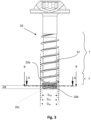
- Fig. 3 shows a side view of a screw according to the invention, wherein three attachment threads 20a, 20b, 20c are provided and the main thread 32 in the attachment area AB has a smaller diameter than the attachment threads 20a, 20b, 20c.
- the main thread 32 therefore begins in the attachment area AB between the attachment threads 20a, 20b, 20c and increases in diameter such that at the end of the attachment area AB it reaches the diameter of the attachment threads 20a, 20b, 20c. From the end of the attachment area AB, the attachment thread 20 runs out and the main thread 32 extends further along the shaft.
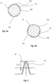
- the diameters of the threads are shown in the cross sections AA in Fig. 4a for the end of the attachment area AB and for the cross section BB of the shaft in Fig. 4b shown.
- the main thread 32 has a groove region F and a support region T following the attachment region AB in the direction of the head.
- the maximum main thread outer diameter D AF is in the forming area F, after which the nut thread is produced after the forming area F.
- the support area T following the forming area in the direction of the drive has an outer diameter D AT that is smaller than the maximum main thread outer diameter D AF . This reduces the friction for the groove area F subsequent load-bearing area T is reduced during the screwing-in process. This results in a low screwing-in torque.
- the invention also relates to screws having a Fig. 1 formed form area F and a according to Fig. 3 designed main thread 32 with a maximum main thread outer diameter D AF in the forming area F and a smaller outer diameter D AT in the supporting area.
- Fig 4a shows a cross-section AA through the screw shaft at the end of the attachment area AB. All threads have the same outer diameter D AA at this position.
- Fig. 4b shows a cross-section BB approximately in the middle of the attachment area AB.
- the main thread 32 is clearly visible here within the outer diameter D AA defined by the attachment threads 20a, 20b, 20c.
- Fig. 5 shows a comparison of the thread profile contour in the forming area and a thread profile contour in the supporting area of the main thread.
- Fig. 5 further shows that the thread cross-sectional profile 38 in the region of the maximum main thread outer diameter D AF is larger, at least in its radially outer region E of the thread cross-sectional profile, than the thread cross-sectional profile 36 in the load-bearing region T in this region E.
Landscapes
- Engineering & Computer Science (AREA)
- General Engineering & Computer Science (AREA)
- Mechanical Engineering (AREA)
- Physics & Mathematics (AREA)
- Geometry (AREA)
- Wood Science & Technology (AREA)
- Chemical & Material Sciences (AREA)
- Dispersion Chemistry (AREA)
- Life Sciences & Earth Sciences (AREA)
- Connection Of Plates (AREA)
- Transmission Devices (AREA)
- Surgical Instruments (AREA)
- Forging (AREA)
- Injection Moulding Of Plastics Or The Like (AREA)
- Moulds For Moulding Plastics Or The Like (AREA)
- Dowels (AREA)
Description
- Die Erfindung betrifft eine selbstfurchende Schraube gemäß dem Oberbegriff des Anspruchs 1.
- In bekannter Weise, wie beispielsweise aus der
EP 0948 719 B1 bekannt, umfasst eine Schraube, insbesondere zur Verschraubung in Kunststoff, einen Antrieb und einen gewindetragenden Schaft. Die Schaube umfasst ferner ein Hauptgewinde, wobei das Hauptgewinde einen maximalen Hauptgewindeaußendurchmesser besitzt. Das Hauptgewinde weist einen tragenden und einen furchenden Bereich auf, wobei der furchende Bereich an der Stelle des Gewindegangs endet, an dem das Muttergewinde vollständig hergestellt ist. - Die Schraube weist an ihrem Schaft an ihrem dem Antrieb abgewandten Ende ein Schraubenende auf, wobei das Schraubenende einen Durchmesser von wenigstens 20% des maximalen Hauptgewindeaußendurchmessers besitzt.
- Die
US 3,861,269 B offenbart eine selbstfurchende und lochbildende Schraube mit einem mehrgängigen Spitzenbereich, damit durch die Schraube ein Loch in den zu verbindenden Bauteilen hergestellt werden kann, wobei ein vereinfachtes Eindringen erlaubt werden soll. - Die
JP 2001 107932 A - Es ist Aufgabe der Erfindung eine Schraube anzugeben, deren Einschraubverhalten verbessert ist.
- Die Aufgabe wird durch die kennzeichnenden Merkmale des Anspruchs 1 in Verbindung mit seinen Oberbegriffen gelöst.
- Die Unteransprüche bilden vorteilhafte Weiterbildungen der Erfindung.
- Der Schaft weist im Bereich des Schraubenendes ein Ansetzgewinde auf.
- Erfindungsgemäß umfasst das Ansetzgewinde wenigstens drei Ansetzgewindegänge, wobei der Durchmesser des Hauptgewindes im Ansetzbereich kleiner ist als der Durchmesser des Ansetzgewindes. In dieser Ausgestaltung erfüllen lediglich die Ansetzgewindegänge die Zentrierfunktion, wobei das Hauptgewinde erst im Anschluss das Muttergewinde furcht.
- Die Ansetzgewindegänge erreichen in ihrem Außendurchmesser höchstens 90% des maximalen Hauptgewindeaußendurchmessers. So ist an der Schraube ein Ansetzbereich gebildet, in welchem die Ansetzgewindegänge den gleichen Durchmesserverlauf aufweisen und zudem im Ansetzbereich der Durchmesser des Hauptgewindes kleiner als der Durchmesser der Ansetzgewindegänge ist.
- Dies hat den Vorteil, dass die Ansetzgewindegänge einen schnellen und geraden Ansatz an einem Vorloch in einem Bauteil, insbesondere einem Kunststoffbauteil, ermöglichen, so dass ein dem Furchbereich nachfolgender Tragbereich möglichst genau ausgerichtet ist und so dem durch den Furchbereich vorgefurchte Muttergewinde folgt und dadurch eine geringere Reibung während des Einschraubvorgangs verursacht. Weiter erfindungsgemäß ist vorgesehen, dass sich das Ansetzgewinde höchstens über zwei Windungen erstreckt. Dies sorgt für eine ausreichende Führung, wobei dennoch eine effektive Verschraubung gewährleistet werden kann.
- Bevorzugt beginnen die Ansetzgewindegänge im Bereich des Schraubenendes am Kern und erweitern vom Beginn des Kerns ihren Durchmesser stetig. Dies sorgt für eine gleichmäßige und schnelle Zentrierung der Schraube beim Ansetzen.
- Insbesondere sind die Gewindegänge mit gleichem Außendurchmesser im Ansetzbereich umfänglich gleichverteilt. Dies unterstützt ebenfalls die Zentrierung der Schraube.
- Ferner kann vorgesehen sein, dass der Durchmesser des Schraubenendes wenigstens 30%, wenigstens 40%, wenigstens 50%, wenigstens 60% des Hauptgewindeaußendurchmessers hat. Auf diese Weise wird ein stumpfes Schraubenende geschaffen, so dass nach kurzer Einführdistanz bereits eine Führung durch das Vorloch gegeben ist.
- Besonders bevorzugt haben alle Gewindegänge im Ansetzbereich ihren Anfang in derselben Querschnittsebene. Auf diese Weise kann über den gesamten Ansetzbereich eine gleichmäßige Anlage der Gewindegänge im Ansetzbereich gewährleistet werden.
- Gemäß einer weiteren vorteilhaften Ausgestaltung können alle Gewindegänge im Ansetzbereich die gleiche Gewindegestaltung, insbesondere das gleiche Gewindeprofil, aufweisen.
- Bevorzugt schließt das Ansetzgewinde unmittelbar ans Schraubenende an. Dadurch kann schnell eine Zentrierfunktion ermöglicht werden.
- Alternativ kann das Ansetzgewinde beabstandet zum Schraubenende beginnen. Auf diese Weise kann der Bereich zum Schraubenende hin eine Suchfunktion erfüllen.
- Die Ansetzgewinde und das Hauptgewinde können gewalzte Gewinde sein, wodurch eine kostengünstige Herstellung ermöglicht wird.
- Das Ansetzgewinde und das Hauptgewinde können im Ansetzbereich einen Flankenwinkel aufweisen, der stumpfer ist als der Flankenwinkel des Hauptgewindes außerhalb des Ansetzbereichs. Dadurch kann der Zentrierfunktion des Ansetzbereichs und der Furchfunktion des Hauptgewindes spezifisch Rechnung getragen werden.
- Nachdem das Ansetzgewinde seinen maximalen Außendurchmesser erreicht hat, kann dieses abrupt auslaufen. Dies reduziert die Reibung insbesondere beim Einschrauben in ein enges Vorloch.
- Gemäß der Erfindung können auch Unterbrechungen der Gewindegänge vorliegen, wobei der interpolierte Verlauf des Gewindeaußendurchmessers gleichbleibt.
- Das Eindrehmoment kann erfindungsgemäß weiter dadurch verringert werden, dass der maximale Hauptgewindeaußendurchmesser im Furchbereich liegt, wobei zudem der Außendurchmesser im Tragbereich geringer ist. Dies führt dazu, dass die dem Furchbereich nachfolgenden Windungen des Tragbereichs in ein geringfügig größer gefurchtes Muttergewinde eingeschraubt werden, wodurch die Reibung der Gewindegänge reduziert wird. Dies wirkt sich insbesondere positiv beim Einschrauben in Kunststoff aus.
- Bevorzugt ist das Gewindequerschnittsprofil im Bereich des maximalen Hauptgewindeaußendurchmessers wenigstens in seinem radial äußeren Bereich des Gewindequerschnittsprofils größer als das Gewindequerschnittsprofil im Tragbereich in diesem Bereich. Der radial äußere Bereich liegt etwa bei 85% des maximalen Hauptgewindedurchmessers.
- Weitere Vorteile, Merkmale und Anwendungsmöglichkeiten der vorliegenden Erfindung ergeben sich aus der nachfolgenden Beschreibung in Verbindung mit den in den Zeichnungen dargestellten Ausführungsbeispielen.
- In der Zeichnung bedeutet:
- Fig. 1
- eine Seitenansicht, einer nicht erfindungsgemäßen Schraube;
- Fig. 2
- einen Querschnitt B-B durch den Schraubenschaft im Ansetzbereich gemäß
Fig.1 ; - Fig. 3
- eine Seitenansicht einer erfindungsgemäßen Schraube mit drei Ansetzgewindegängen;
- Fig. 4a
- einen Querschnitt A-A durch den Schraubenschaft im Ansetzbereich gemäß
Fig. 3 ; - Fig. 4b
- einen Querschnitt B-B durch den Schraubenschaft im Ansetzbereich gemäß
Fig. 3 ; - Fig. 5
- ein Vergleich der Gewindeprofilkontur im Formbereich und einer Gewindeprofilkontur im Tragbereich des Hauptgewindes.
-
Fig. 1 zeigt eine nicht erfindungsgemäße selbstfurchende Schraube 10 mit einem Schaft 14 und einem Antrieb 12. Der gewindetragende Schaft 14 trägt ein Hauptgewinde 16, das einen Furchbereich F und einen Tragbereich T aufweist. Der Furchbereich F endet an der Stelle des Hauptgewindes 16, an der das vollständige Muttergewinde hergestellt ist, wonach der Tragbereich T folgt. Dies ist nach etwa zwei Windungen des Hauptgewindes 16 ausgehend vom freien Ende der Schraube 18 der Fall. - In diesem Beispiel sind der Furchbereich F und der Tragbereich T Teile des gleichen Gewindegangs, so dass sich kein gegenständlicher Übergang zwischen dem Tragbereich T und dem Furchbereich F ergibt. An dem dem Antrieb gegenüberliegenden Ende der Schraube, also der "Spitze", ist ein Ansetzbereich AB vorgesehen. Der Ansetzbereich AB wird im vorliegenden Beispiel dadurch gebildet, dass zwei Ansetzgewindegänge 20a, 20b sich unmittelbar am Schraubenende 18 ausgehend vom Schraubenkern erheben und in Richtung des Antriebs 12 ihren Durchmesser DAA, bis zum Ende des Ansetzbereichs AB stetig erweitern. Die Ansetzgewindegänge 20a, 20b weisen am Ende des Ansetzbereichs AB ihren maximalen Außendurchmesser DAA auf. Dieser beträgt weniger als 90% des Durchmessers DAF des Hauptgewindes 18. Entsprechend kann eine Beeinträchtigung der Halteeigenschaften durch das Ansetzgewinde 20 vermieden werden und dennoch ein zentriertes und gerades Ansetzen der Schraube 10 gefördert werden. Das Hauptgewinde 16 verläuft im Ansetzbereich AB gleich mit den Ansetzgewindegängen 20a, 20b.
-
Fig. 2 zeigt einen Querschnitt B-B etwa in der Mitte des Ansetzbereichs AB. Der Querschnitt zeigt die Ansetzgewindegänge 20a, 20b und den Hauptgewindegang 16. Alle Gewindegänge weisen an der Stelle den gleichen Durchmesser DAA auf. Der Durchmesser DAA vergrößert sich ausgehend vom Schraubenende in Richtung des Antriebs stetig, wobei der Durchmesser aber in jeder Querschnittsebene im Ansetzbereich AB gleich ist. -
Fig. 3 zeigt eine Seitenansicht einer erfindungsgemäßen Schraube, wobei drei Ansetzgewinde 20a, 20b, 20c vorgesehen sind und das Hauptgewinde 32 im Ansetzbereich AB einen geringeren Durchmesser aufweist als die Ansetzgewinde 20a, 20b, 20c. - Das Hauptgewinde 32 beginnt also im Ansetzbereich AB zwischen den Ansetzgewindegängen 20a, 20b, 20c und steigt in seinem Durchmesser derart an, dass es am Ende des Ansetzbereichs AB den Durchmesser der Ansetzgewindegänge 20a, 20b, 20c erreicht. Ab dem Ende des Ansetzbereichs AB läuft das Ansetzgewinde 20 aus und das Hauptgewinde 32 erstreckt sich weiter entlang des Schafts. Die Durchmesser der Gewindegänge sind in den Querschnitten A-A in
Fig. 4a für das Ende des Ansetzbereichs AB und für den Querschnitt B-B des Schafts inFig. 4b dargestellt. - Ferner weist der Hauptgewindegang 32 im Anschluss an den Ansetzbereich AB in Richtung des Kopfes einen Furchbereich F und einen Tragbereich T auf.
- Der maximale Hauptgewindeaußendurchmesser DAF liegt im Formbereich F, wonach nach dem Formbereich F das Muttergewinde hergestellt ist. Der dem Formbereich in Richtung des Antriebs nachfolgende Tragbereich T weist einen Außendurchmesser DAT auf, der geringer ist als der maximale Hauptgewindeaußendurchmesser DAF. Dadurch wird die Reibung für den dem Furchbereich F nachfolgenden Tragbereich T beim Einschraubvorgang reduziert. Insoweit ergibt sich ein geringes Einschraubmoment.
- Es versteht sich, dass die Erfindung sich auch auf Schrauben bezieht, die einen gemäß
Fig. 1 ausgebildeten Formbereich F und einen gemäßFig. 3 ausgestaltetes Hauptgewinde 32 mit einem im Formbereich F liegenden maximalen Hauptgewindeaußendurchmesser DAF und einen geringeren Außendurchmesser DAT im Tragbereich aufweisen. -
Fig 4a zeigt einen Querschnitt A-A durch den Schraubenschaft am Ende des Ansetzbereichs AB. Alle Gewinde weisen an dieser Position den gleichen Außendurchmesser DAA auf. -
Fig. 4b zeigt einen Querschnitt B-B etwa in der Mitte des Ansetzbereichs AB. Der Hauptgewindegang 32 liegt hier deutlich erkennbar innerhalb des durch die Ansetzgewindegänge 20a, 20b, 20c definierten Außendurchmessers DAA. -
Fig. 5 zeigt einen Vergleich der Gewindeprofilkontur im Formbereich und einer Gewindeprofilkontur im Tragbereich des Hauptgewindes.Fig. 5 zeigt weiter, dass das Gewindequerschnittsprofil 38 im Bereich des maximalen Hauptgewindeaußendurchmessers DAF wenigstens in seinem radial äußeren Bereich E des Gewindequerschnittsprofils größer ist als das Gewindequerschnittsprofil 36 im Tragbereich T in diesem Bereich E.
Claims (14)
- Selbstfurchende Schraube (10, 30) umfassend einen Antrieb (12) und einen gewindetragenden Schaft (14) umfassend ein Hauptgewinde (16, 32), wobei das Hauptgewinde (16, 32) einen maximalen Hauptgewindeaußendurchmesser (DAF) besitzt und einen Furchbereich (F) und einen in Richtung des Antriebs (12) nachfolgenden Tragbereich (T) aufweist, wobei der Schaft (14) an einem dem Antrieb (12) abgewandten Ende ein Schraubenende (18) aufweist, wobei das Schraubenende (18) einen Durchmesser (DE) von wenigstens 20% des maximalen Hauptgewindeaußendurchmessers (DAF) aufweist der Schaft ferner im Bereich des Schraubenendes (18) ein Ansetzgewinde (20) aufweist, dadurch gekennzeichnet, dass das Ansetzgewinde (20) wenigstens drei Ansetzgewindegänge (20a, 20b, 20c) umfasst, die in ihrem Außendurchmesser (DAA) höchstens 90% des maximalen Hauptgewindeaußendurchmessers (DAF) erreichen und einen Ansetzbereich bilden, in welchem die Ansetzgewindegänge (20a, 20b, 20c) den gleichen Durchmesserverlauf aufweisen und zudem im Ansetzbereich (AB) der Durchmesser des Hauptgewindes (16, 32) kleiner ist als der Durchmesser (DAA) der Ansetzgewindegänge (20a, 20b, 20c), wobei das Ansetzgewinde (20) sich höchstens über zwei Windungen erstreckt.
- Selbstfurchende Schraube nach einem der vorangehenden Ansprüche, dadurch gekennzeichnet, dass die Ansetzgewindegänge (20a, 20b, 20c) im Bereich des Schraubenendes (18) am Kern beginnen und ihren Durchmesser stetig erweitern.
- Selbstfurchende Schraube nach einem der vorangehenden Ansprüche, dadurch gekennzeichnet, dass die Gewindegänge (20a, 20b, 20c, 16) mit gleichem Außendurchmesser (DAA, D) im Ansetzbereich (AB) umfänglich gleichverteilt sind.
- Selbstfurchende Schraube nach einem der vorangehenden Ansprüche, dadurch gekennzeichnet, dass der Durchmesser (DE) des Schraubenendes (18) wenigstens 20%, wenigstens 30%, wenigstens 40%, wenigstens 50%, wenigstens 60 % des Hauptgewindeaußendurchmessers (DAF) hat.
- Selbstfurchende Schraube nach einem der vorangehenden Ansprüche, dadurch gekennzeichnet, dass alle Gewindegänge im Ansetzbereich (AB) ihren Anfang in derselben Querschnittsebene haben.
- Selbstfurchende Schraube nach Anspruch 5, dadurch gekennzeichnet, dass alle Gewindegänge (20a, 20b, 16) im Ansetzbereich (AB) die gleiche Gewindegestaltung aufweisen.
- Selbstfurchende Schraube nach einem der vorangehenden Ansprüche, dadurch gekennzeichnet, dass das Ansetzgewinde (20) unmittelbar ans Schraubenende (18) anschließt.
- Selbstfurchende Schraube nach einem der vorangehenden Ansprüche 1 bis 6, dadurch gekennzeichnet, dass das Ansetzgewinde (20) beabstandet zum Schraubenende (18) beginnt.
- Selbstfurchende Schraube nach einem der vorangehenden Ansprüche, dadurch gekennzeichnet, dass das Ansetzgewinde (20) und das Hauptgewinde (16) gewalzte Gewinde sind.
- Selbstfurchende Schraube nach einem der vorangehenden Ansprüche, dadurch gekennzeichnet, dass das Ansetzgewinde (20) und Hauptgewinde (16) im Ansetzbereich (AB) einen stumpferen Flankenwinkel haben als das Hauptgewinde (16) außerhalb des Ansetzbereichs.
- Selbstfurchende Schraube nach einem der vorangehenden Ansprüche, dadurch gekennzeichnet, dass das Ansetzgewinde (20) abrupt ausläuft.
- Selbstfurchende Schraube nach einem der vorangehenden Ansprüche, dadurch gekennzeichnet, dass Unterbrechungen der Gewindegänge vorgesehen sind, wobei der interpolierte Verlauf des Gewindeaußendurchmessers gleichbleibt.
- Selbstfurchende Schraube nach einem der vorangehenden Ansprüche, dadurch gekennzeichnet, dass der maximale Hauptgewindeaußendurchmesser (DAF) im Furchbereich (F) liegt, wobei der Außendurchmesser (DAT) im Tragbereich (T) geringer ist.
- Selbstfurchende Schraube nach Anspruch 13, dadurch gekennzeichnet, dass das Gewindequerschnittsprofil (38) im Bereich des maximalen Hauptgewindeaußendurchmessers (DAF) wenigstens in seinem radial äußeren Bereich (E) des Gewindequerschnittsprofils größer ist als das Gewindequerschnittsprofil (36) im Tragbereich (T) in diesem Bereich (E).
Applications Claiming Priority (2)
| Application Number | Priority Date | Filing Date | Title |
|---|---|---|---|
| DE102018114983.2A DE102018114983A1 (de) | 2018-06-21 | 2018-06-21 | Selbstfurchende Schraube |
| PCT/EP2019/066533 WO2019243608A1 (de) | 2018-06-21 | 2019-06-21 | Selbstfurchende schraube |
Publications (3)
| Publication Number | Publication Date |
|---|---|
| EP3810942A1 EP3810942A1 (de) | 2021-04-28 |
| EP3810942B1 true EP3810942B1 (de) | 2025-02-05 |
| EP3810942C0 EP3810942C0 (de) | 2025-02-05 |
Family
ID=67226213
Family Applications (1)
| Application Number | Title | Priority Date | Filing Date |
|---|---|---|---|
| EP19737669.2A Active EP3810942B1 (de) | 2018-06-21 | 2019-06-21 | Selbstfurchende schraube |
Country Status (16)
| Country | Link |
|---|---|
| US (1) | US11754110B2 (de) |
| EP (1) | EP3810942B1 (de) |
| JP (1) | JP7414740B2 (de) |
| KR (1) | KR102848171B1 (de) |
| CN (1) | CN112534144B (de) |
| CA (1) | CA3102912A1 (de) |
| DE (1) | DE102018114983A1 (de) |
| ES (1) | ES3026219T3 (de) |
| MX (1) | MX2020013342A (de) |
| MY (1) | MY208270A (de) |
| PH (1) | PH12020552204A1 (de) |
| PL (1) | PL3810942T3 (de) |
| SG (1) | SG11202012666SA (de) |
| TW (1) | TWI811385B (de) |
| WO (1) | WO2019243608A1 (de) |
| ZA (1) | ZA202007910B (de) |
Families Citing this family (2)
| Publication number | Priority date | Publication date | Assignee | Title |
|---|---|---|---|---|
| USD1012685S1 (en) * | 2020-02-11 | 2024-01-30 | B.M.B. Investments Pty Ltd | Screw |
| USD999053S1 (en) * | 2020-02-11 | 2023-09-19 | B.M.B Investments Pty Ltd | Screw |
Citations (1)
| Publication number | Priority date | Publication date | Assignee | Title |
|---|---|---|---|---|
| JP2001107932A (ja) * | 1999-10-13 | 2001-04-17 | Fukasawa:Kk | ネ ジ |
Family Cites Families (47)
| Publication number | Priority date | Publication date | Assignee | Title |
|---|---|---|---|---|
| US3079968A (en) * | 1959-08-26 | 1963-03-05 | Nylok Corp | Self-locking self-tapping sheet metal screws |
| GB1004883A (en) | 1962-03-20 | 1965-09-15 | Res Eng & Mfg | Improvements in self-tapping screws |
| US3861269A (en) * | 1971-01-04 | 1975-01-21 | Superior Dry Wall Screw Mfg Co | Fastener with improved thread construction |
| US3703843A (en) * | 1971-01-04 | 1972-11-28 | Msl Ind Inc | Fastener with improved thread construction |
| US3935785A (en) * | 1974-01-03 | 1976-02-03 | Rockford Headed Products, Inc. | Thread swaging screw |
| US3875780A (en) * | 1974-01-03 | 1975-04-08 | Rockford Headed Products | Method of making a thread forming screw |
| JPS53104060A (en) * | 1977-02-23 | 1978-09-09 | Yamashina Seikoushiyo Kk | Selffextruding fastener |
| DE3510300A1 (de) * | 1985-03-22 | 1986-09-25 | Alfred Teves GmbH & Co oHG, 5275 Bergneustadt | Befestigungsschraube, insbesondere fuer stossfaenger von kraftfahrzeugen |
| JPH041371Y2 (de) | 1987-02-16 | 1992-01-17 | ||
| US5273383A (en) * | 1991-04-04 | 1993-12-28 | Research Engineering & Manufacturing, Inc. | Threaded fastener for use in thermoplastics and roll die for producing same |
| US5190426A (en) * | 1992-03-02 | 1993-03-02 | Illinois Tool Works Inc. | Concrete fastener |
| RU94033305A (ru) | 1994-09-13 | 1996-07-27 | В.И. Ураждин | Самонарезающий винт |
| JP3290362B2 (ja) * | 1996-09-30 | 2002-06-10 | 日東精工株式会社 | 軟質金属材用タッピンねじ |
| EP0948719B1 (de) | 1997-07-29 | 2001-12-05 | EJOT VERBINDUNGSTECHNIK GmbH & Co. KG | Befestigungsschraube mit selbstfurchendem gewinde |
| CZ293306B6 (cs) | 1997-07-29 | 2004-03-17 | Ejot Verbindungstechnik Gmbh & Co. Kg | Šroub se samořezným závitem |
| US5885041A (en) * | 1997-08-04 | 1999-03-23 | Anthony C. Giannuzzi | Chemical self-tapping, screw-type masonry anchor |
| JP3942243B2 (ja) * | 1997-08-18 | 2007-07-11 | 若井産業株式会社 | 転造ねじとその製造方法 |
| ES2231434T3 (es) | 2000-05-19 | 2005-05-16 | Pama Reiter Stefan | Taco roscado en forma de manguito que enrosca en una ranura. |
| AUPQ919200A0 (en) * | 2000-08-04 | 2000-08-24 | Hanstock Fasteners Pty Limited | Improvements relating to screws for concrete and masonry |
| US7156600B2 (en) * | 2001-06-19 | 2007-01-02 | Illinois Tool Works Inc. | Die for, method of making, and fastener with lobed primary thread lead and interposed dual auxiliary thread lead with improved substrate entry end portion |
| GB2386405A (en) * | 2002-03-15 | 2003-09-17 | Charles Bickford | Threaded fixing device and method |
| US6918727B2 (en) * | 2002-05-01 | 2005-07-19 | Joker Industrial Co., Ltd. | Anchoring screw with double heads and triple threads of different depths of thread |
| JP2007100741A (ja) * | 2005-09-30 | 2007-04-19 | Nitto Seiko Co Ltd | タッピンねじ |
| DE202006000479U1 (de) | 2006-01-12 | 2006-03-16 | Abc Verbindungstechnik Gmbh & Co. Kg | Selbstlochende und gewindeformende Schraube |
| JP2007285336A (ja) * | 2006-04-13 | 2007-11-01 | Japan Power Fastening Co Ltd | もみ切り式自己穿孔ねじ |
| US7950888B2 (en) | 2006-04-13 | 2011-05-31 | Japan Power Fastening Co., Ltd. | Self-penetrating screw |
| JP2007292201A (ja) * | 2006-04-25 | 2007-11-08 | Japan Power Fastening Co Ltd | ドリルねじ |
| DE102007024240A1 (de) * | 2007-05-18 | 2008-11-20 | Swg Schraubenwerk Gaisbach Gmbh | Schraube |
| GB2455533B (en) * | 2007-12-12 | 2011-08-10 | Excalibur Screwbolts Ltd | A fixing device |
| DE102008041467A1 (de) * | 2008-08-22 | 2010-02-25 | Hilti Aktiengesellschaft | Befestigungselement |
| JP2011007932A (ja) | 2009-06-24 | 2011-01-13 | Sony Ericsson Mobilecommunications Japan Inc | 携帯端末装置、音声の合成方法、及び音声の合成プログラム |
| TWM368721U (en) * | 2009-07-21 | 2009-11-11 | Fong Prean Ind Co Ltd | Improved screw (19) |
| TWM385613U (en) | 2010-01-12 | 2010-08-01 | Hwally Products Co Ltd | screw |
| JP2011256971A (ja) | 2010-06-11 | 2011-12-22 | Pias Hanbai Kk | タッピンねじ |
| DE102010031410A1 (de) * | 2010-07-15 | 2012-01-19 | TOGE-Dübel A. Gerhard KG | Selbstzentrierende Schraube |
| BR112013027513B1 (pt) * | 2011-04-28 | 2020-03-31 | Nitto Seiko Co., Ltd | Parafuso auto-atarraxante |
| US20130302111A1 (en) | 2012-05-10 | 2013-11-14 | Sheng-Tsai SHIH | Concrete screw structure |
| DE102012215645C5 (de) * | 2012-06-15 | 2021-10-28 | Reisser Schraubentechnik Gmbh | Schraube und ihre Verwendung |
| US20130336744A1 (en) * | 2012-06-15 | 2013-12-19 | Infastech Intellectual Properties Pte. Ltd. | Threaded masonry fastener |
| JP5607114B2 (ja) * | 2012-06-26 | 2014-10-15 | 株式会社トープラ | タッピンねじ |
| GB201219704D0 (en) * | 2012-11-01 | 2012-12-12 | Excalibur Screwbolts Ltd | A process for manufacturing a fixing device |
| TWM489214U (en) * | 2014-07-31 | 2014-11-01 | King Point Enterprise Co Ltd | Cement expansion bolt |
| US9581183B2 (en) * | 2015-02-17 | 2017-02-28 | The Hillman Group, Inc. | Screw-type fastener |
| TWM518279U (zh) * | 2015-11-23 | 2016-03-01 | Shuenn Chang Fa Entpr Co Ltd | 可提升鎖固力的複合螺絲 |
| DE102015120470A1 (de) * | 2015-11-26 | 2017-06-01 | Fischerwerke Gmbh & Co. Kg | Betonschraube |
| DE102016109460A1 (de) * | 2016-05-23 | 2017-11-23 | Apolo Mea Befestigungssysteme Gmbh | Befestigungsvorrichtung zur befestigung eines gegenstandes an einem weichen, druckfesten material |
| TWI623690B (zh) * | 2017-01-25 | 2018-05-11 | Cement screw |
-
2018
- 2018-06-21 DE DE102018114983.2A patent/DE102018114983A1/de active Pending
-
2019
- 2019-06-18 TW TW108121141A patent/TWI811385B/zh active
- 2019-06-21 PL PL19737669.2T patent/PL3810942T3/pl unknown
- 2019-06-21 ES ES19737669T patent/ES3026219T3/es active Active
- 2019-06-21 MX MX2020013342A patent/MX2020013342A/es unknown
- 2019-06-21 CN CN201980041060.9A patent/CN112534144B/zh active Active
- 2019-06-21 JP JP2020570106A patent/JP7414740B2/ja active Active
- 2019-06-21 WO PCT/EP2019/066533 patent/WO2019243608A1/de not_active Ceased
- 2019-06-21 SG SG11202012666SA patent/SG11202012666SA/en unknown
- 2019-06-21 KR KR1020217001885A patent/KR102848171B1/ko active Active
- 2019-06-21 CA CA3102912A patent/CA3102912A1/en active Pending
- 2019-06-21 EP EP19737669.2A patent/EP3810942B1/de active Active
- 2019-06-21 MY MYPI2020006763A patent/MY208270A/en unknown
- 2019-06-21 US US17/251,793 patent/US11754110B2/en active Active
-
2020
- 2020-12-17 PH PH12020552204A patent/PH12020552204A1/en unknown
- 2020-12-17 ZA ZA2020/07910A patent/ZA202007910B/en unknown
Patent Citations (1)
| Publication number | Priority date | Publication date | Assignee | Title |
|---|---|---|---|---|
| JP2001107932A (ja) * | 1999-10-13 | 2001-04-17 | Fukasawa:Kk | ネ ジ |
Also Published As
| Publication number | Publication date |
|---|---|
| JP2021529287A (ja) | 2021-10-28 |
| SG11202012666SA (en) | 2021-02-25 |
| ES3026219T3 (en) | 2025-06-10 |
| PL3810942T3 (pl) | 2025-05-26 |
| PH12020552204A1 (en) | 2021-08-16 |
| CN112534144B (zh) | 2022-11-04 |
| JP7414740B2 (ja) | 2024-01-16 |
| US20210115959A1 (en) | 2021-04-22 |
| CA3102912A1 (en) | 2019-12-26 |
| KR20210021562A (ko) | 2021-02-26 |
| TW202001108A (zh) | 2020-01-01 |
| TWI811385B (zh) | 2023-08-11 |
| DE102018114983A1 (de) | 2019-12-24 |
| EP3810942A1 (de) | 2021-04-28 |
| BR112020025324A2 (pt) | 2021-03-09 |
| ZA202007910B (en) | 2025-09-25 |
| EP3810942C0 (de) | 2025-02-05 |
| MX2020013342A (es) | 2021-02-02 |
| US11754110B2 (en) | 2023-09-12 |
| WO2019243608A1 (de) | 2019-12-26 |
| MY208270A (en) | 2025-04-29 |
| CN112534144A (zh) | 2021-03-19 |
| KR102848171B1 (ko) | 2025-08-19 |
Similar Documents
| Publication | Publication Date | Title |
|---|---|---|
| EP1971786B1 (de) | Selbstlochende und gewindeformende schraube | |
| DE19902461B4 (de) | Mutter mit T-förmigem Querschnitt | |
| EP2454494B1 (de) | Selbstlochformendes befestigungselement | |
| DE4041765C2 (de) | Einschraubdübel | |
| DE4333791A1 (de) | Gewindeschneidschraube | |
| EP0088366A1 (de) | Gewindeselbstformende Schraube | |
| EP3719330B1 (de) | Schraube mit diskontinuität an zwischengewindeabschnitt | |
| DE102015107467A1 (de) | Schraube mit unterbrochenen Schabekanten | |
| EP3097313B1 (de) | Schraube, befestigungsanordnung und verwendung einer schraube | |
| EP3374649B1 (de) | Gewindeformende schraube | |
| EP3655669A1 (de) | Holzschraube | |
| EP3810941B1 (de) | Schraube zur verschraubung in kunststoff | |
| DE102015223473A1 (de) | Buchse, Befestigungselement und Verfahren zum Anordnen eines Befestigungselements an einem Werkstück | |
| EP3810942A1 (de) | Selbstfurchende schraube | |
| DE4108771A1 (de) | Spanplattenschraube | |
| DE2537446C3 (de) | Selbstschneidende Blechschraube | |
| EP3586015B1 (de) | Schraube | |
| EP0799386B1 (de) | Loch- und gewindeformende schraube sowie verfahren zum eindrehen derselben | |
| EP4450836B1 (de) | Holzschraube | |
| EP1262669B1 (de) | Spanlos loch- und gewindeformende Schraube | |
| DE102020119633A1 (de) | Holz- oder Kunststoffschraube | |
| EP3029340B1 (de) | Gewindehülse | |
| EP0713013B1 (de) | Kunststoffdübel | |
| DE102017002069A1 (de) | Einschraubdübel und Befestigungssystem mit einem Einschraubdübel | |
| DE10204441B4 (de) | Blindniet |
Legal Events
| Date | Code | Title | Description |
|---|---|---|---|
| STAA | Information on the status of an ep patent application or granted ep patent |
Free format text: STATUS: UNKNOWN |
|
| STAA | Information on the status of an ep patent application or granted ep patent |
Free format text: STATUS: THE INTERNATIONAL PUBLICATION HAS BEEN MADE |
|
| PUAI | Public reference made under article 153(3) epc to a published international application that has entered the european phase |
Free format text: ORIGINAL CODE: 0009012 |
|
| STAA | Information on the status of an ep patent application or granted ep patent |
Free format text: STATUS: REQUEST FOR EXAMINATION WAS MADE |
|
| 17P | Request for examination filed |
Effective date: 20210119 |
|
| AK | Designated contracting states |
Kind code of ref document: A1 Designated state(s): AL AT BE BG CH CY CZ DE DK EE ES FI FR GB GR HR HU IE IS IT LI LT LU LV MC MK MT NL NO PL PT RO RS SE SI SK SM TR |
|
| AX | Request for extension of the european patent |
Extension state: BA ME |
|
| RIN1 | Information on inventor provided before grant (corrected) |
Inventor name: ACHENBACH, MICHAEL Inventor name: BEHLE, JUERGEN Inventor name: BIRKELBACH, RALF Inventor name: DIECKMANN, VOLKER Inventor name: DRATSCHMIDT, FRANK Inventor name: HACKLER, JAN Inventor name: GERBER, RENE Inventor name: HELLMIG, RALPH J. Inventor name: SELIMI, ILIR Inventor name: WEITZEL, STEPHAN |
|
| DAV | Request for validation of the european patent (deleted) | ||
| DAX | Request for extension of the european patent (deleted) | ||
| STAA | Information on the status of an ep patent application or granted ep patent |
Free format text: STATUS: EXAMINATION IS IN PROGRESS |
|
| 17Q | First examination report despatched |
Effective date: 20230316 |
|
| RAP1 | Party data changed (applicant data changed or rights of an application transferred) |
Owner name: EJOT SE & CO. KG |
|
| GRAP | Despatch of communication of intention to grant a patent |
Free format text: ORIGINAL CODE: EPIDOSNIGR1 |
|
| STAA | Information on the status of an ep patent application or granted ep patent |
Free format text: STATUS: GRANT OF PATENT IS INTENDED |
|
| INTG | Intention to grant announced |
Effective date: 20240906 |
|
| GRAS | Grant fee paid |
Free format text: ORIGINAL CODE: EPIDOSNIGR3 |
|
| GRAA | (expected) grant |
Free format text: ORIGINAL CODE: 0009210 |
|
| STAA | Information on the status of an ep patent application or granted ep patent |
Free format text: STATUS: THE PATENT HAS BEEN GRANTED |
|
| AK | Designated contracting states |
Kind code of ref document: B1 Designated state(s): AL AT BE BG CH CY CZ DE DK EE ES FI FR GB GR HR HU IE IS IT LI LT LU LV MC MK MT NL NO PL PT RO RS SE SI SK SM TR |
|
| REG | Reference to a national code |
Ref country code: GB Ref legal event code: FG4D Free format text: NOT ENGLISH |
|
| REG | Reference to a national code |
Ref country code: CH Ref legal event code: EP |
|
| REG | Reference to a national code |
Ref country code: DE Ref legal event code: R096 Ref document number: 502019012902 Country of ref document: DE |
|
| REG | Reference to a national code |
Ref country code: IE Ref legal event code: FG4D Free format text: LANGUAGE OF EP DOCUMENT: GERMAN |
|
| U01 | Request for unitary effect filed |
Effective date: 20250227 |
|
| U07 | Unitary effect registered |
Designated state(s): AT BE BG DE DK EE FI FR IT LT LU LV MT NL PT RO SE SI Effective date: 20250307 |
|
| REG | Reference to a national code |
Ref country code: ES Ref legal event code: FG2A Ref document number: 3026219 Country of ref document: ES Kind code of ref document: T3 Effective date: 20250610 |
|
| U20 | Renewal fee for the european patent with unitary effect paid |
Year of fee payment: 7 Effective date: 20250528 |
|
| PG25 | Lapsed in a contracting state [announced via postgrant information from national office to epo] |
Ref country code: RS Free format text: LAPSE BECAUSE OF FAILURE TO SUBMIT A TRANSLATION OF THE DESCRIPTION OR TO PAY THE FEE WITHIN THE PRESCRIBED TIME-LIMIT Effective date: 20250505 |
|
| PGFP | Annual fee paid to national office [announced via postgrant information from national office to epo] |
Ref country code: PL Payment date: 20250606 Year of fee payment: 7 |
|
| PGFP | Annual fee paid to national office [announced via postgrant information from national office to epo] |
Ref country code: GB Payment date: 20250620 Year of fee payment: 7 |
|
| PG25 | Lapsed in a contracting state [announced via postgrant information from national office to epo] |
Ref country code: NO Free format text: LAPSE BECAUSE OF FAILURE TO SUBMIT A TRANSLATION OF THE DESCRIPTION OR TO PAY THE FEE WITHIN THE PRESCRIBED TIME-LIMIT Effective date: 20250505 Ref country code: IS Free format text: LAPSE BECAUSE OF FAILURE TO SUBMIT A TRANSLATION OF THE DESCRIPTION OR TO PAY THE FEE WITHIN THE PRESCRIBED TIME-LIMIT Effective date: 20250605 |
|
| PG25 | Lapsed in a contracting state [announced via postgrant information from national office to epo] |
Ref country code: HR Free format text: LAPSE BECAUSE OF FAILURE TO SUBMIT A TRANSLATION OF THE DESCRIPTION OR TO PAY THE FEE WITHIN THE PRESCRIBED TIME-LIMIT Effective date: 20250205 |
|
| PG25 | Lapsed in a contracting state [announced via postgrant information from national office to epo] |
Ref country code: GR Free format text: LAPSE BECAUSE OF FAILURE TO SUBMIT A TRANSLATION OF THE DESCRIPTION OR TO PAY THE FEE WITHIN THE PRESCRIBED TIME-LIMIT Effective date: 20250506 |
|
| PGFP | Annual fee paid to national office [announced via postgrant information from national office to epo] |
Ref country code: CZ Payment date: 20250610 Year of fee payment: 7 |
|
| PG25 | Lapsed in a contracting state [announced via postgrant information from national office to epo] |
Ref country code: SM Free format text: LAPSE BECAUSE OF FAILURE TO SUBMIT A TRANSLATION OF THE DESCRIPTION OR TO PAY THE FEE WITHIN THE PRESCRIBED TIME-LIMIT Effective date: 20250205 |
|
| PGFP | Annual fee paid to national office [announced via postgrant information from national office to epo] |
Ref country code: ES Payment date: 20250718 Year of fee payment: 7 |
|
| PGFP | Annual fee paid to national office [announced via postgrant information from national office to epo] |
Ref country code: CH Payment date: 20250701 Year of fee payment: 7 |
|
| PG25 | Lapsed in a contracting state [announced via postgrant information from national office to epo] |
Ref country code: SK Free format text: LAPSE BECAUSE OF FAILURE TO SUBMIT A TRANSLATION OF THE DESCRIPTION OR TO PAY THE FEE WITHIN THE PRESCRIBED TIME-LIMIT Effective date: 20250205 |
|
| PLBE | No opposition filed within time limit |
Free format text: ORIGINAL CODE: 0009261 |
|
| STAA | Information on the status of an ep patent application or granted ep patent |
Free format text: STATUS: NO OPPOSITION FILED WITHIN TIME LIMIT |
|
| REG | Reference to a national code |
Ref country code: CH Ref legal event code: L10 Free format text: ST27 STATUS EVENT CODE: U-0-0-L10-L00 (AS PROVIDED BY THE NATIONAL OFFICE) Effective date: 20251217 |
|
| 26N | No opposition filed |
Effective date: 20251106 |
|
| PG25 | Lapsed in a contracting state [announced via postgrant information from national office to epo] |
Ref country code: MC Free format text: LAPSE BECAUSE OF FAILURE TO SUBMIT A TRANSLATION OF THE DESCRIPTION OR TO PAY THE FEE WITHIN THE PRESCRIBED TIME-LIMIT Effective date: 20250205 |
|
| REG | Reference to a national code |
Ref country code: CH Ref legal event code: R17 Free format text: ST27 STATUS EVENT CODE: U-0-0-R10-R17 (AS PROVIDED BY THE NATIONAL OFFICE) Effective date: 20260410 |
|
| PG25 | Lapsed in a contracting state [announced via postgrant information from national office to epo] |
Ref country code: IE Free format text: LAPSE BECAUSE OF NON-PAYMENT OF DUE FEES Effective date: 20250621 |