EP3801170B1 - Wischplatte - Google Patents
Wischplatte Download PDFInfo
- Publication number
- EP3801170B1 EP3801170B1 EP19725110.1A EP19725110A EP3801170B1 EP 3801170 B1 EP3801170 B1 EP 3801170B1 EP 19725110 A EP19725110 A EP 19725110A EP 3801170 B1 EP3801170 B1 EP 3801170B1
- Authority
- EP
- European Patent Office
- Prior art keywords
- mop
- joint
- plate
- head
- joint body
- Prior art date
- Legal status (The legal status is an assumption and is not a legal conclusion. Google has not performed a legal analysis and makes no representation as to the accuracy of the status listed.)
- Active
Links
Images


Classifications
-
- A—HUMAN NECESSITIES
- A47—FURNITURE; DOMESTIC ARTICLES OR APPLIANCES; COFFEE MILLS; SPICE MILLS; SUCTION CLEANERS IN GENERAL
- A47L—DOMESTIC WASHING OR CLEANING; SUCTION CLEANERS IN GENERAL
- A47L13/00—Implements for cleaning floors, carpets, furniture, walls, or wall coverings
- A47L13/10—Scrubbing; Scouring; Cleaning; Polishing
- A47L13/20—Mops
- A47L13/24—Frames for mops; Mop heads
- A47L13/25—Wire frames
- A47L13/253—Wire frames of adjustable or foldable type
-
- A—HUMAN NECESSITIES
- A47—FURNITURE; DOMESTIC ARTICLES OR APPLIANCES; COFFEE MILLS; SPICE MILLS; SUCTION CLEANERS IN GENERAL
- A47L—DOMESTIC WASHING OR CLEANING; SUCTION CLEANERS IN GENERAL
- A47L13/00—Implements for cleaning floors, carpets, furniture, walls, or wall coverings
- A47L13/10—Scrubbing; Scouring; Cleaning; Polishing
- A47L13/20—Mops
- A47L13/24—Frames for mops; Mop heads
- A47L13/254—Plate frames
- A47L13/258—Plate frames of adjustable or foldable type
Definitions
- the invention relates to a mop plate comprising a base body to which a first mop plate wing, a second mop plate wing and a joint are connected, wherein the mop plate wings can be pivoted between a working position and a wringing position.
- Such a wiper plate is, for example, from the EN 10 2012 007 525 A1 known.
- the mop plate forms part of a mop device, whereby the mop device has a handle in addition to the mop plate, which is connected to the mop plate via the joint.
- the mop plate is assigned a mop cover, which is detachably attached to the mop plate so that it can be brought into contact with the floor to be cleaned. The mop plate presses the mop cover flat onto the floor to be cleaned.
- the mop plate wings are moved from the working position to the wringing position.
- the mop cover hangs down from the mop plate in the form of a loop.
- the mop cover hanging down from the mop plate can be wrung out in a basket-shaped wringing device by pressing the mop device.
- the mop covers are pressed into a rotating wringing device in which the mop cover is wrung out together with the mop plate by quickly rotating the wringing basket.
- it is advantageous for easy insertion of the mop device if the mop plate with the mop cover is placed straight into the wringing device. is pressed in.
- With a manual wringing device where wringing is done by pressing in the wiping plate, it is problematic that the joint can tilt during pressing in, which reduces the force that can be applied and worsens the execution result.
- a mop plate which is connected to a handle in an articulated manner, whereby the articulated connection can be locked via a locking device.
- the CN 2887238 Y shows a butterfly mop in which the mop plate is connected to the handle via several joints, whereby the joints block each other in the wringing position.
- the invention is based on the object of providing a wiping plate which can be fed particularly easily to a wringing device.
- a device for locking the joint is arranged in the base body, which fixes the joint along the longitudinal axis when the mop plate wings are outside the working position.
- the joint is fixed along the longitudinal axis by the device for locking when the mop plate wings pivot from the working position into the wringing position.
- fixation is also provided according to the invention when the mop plate wings are in the wringing position. This ensures that the joint can no longer pivot or tilt when the mop plate is pressed into the wringing basket. This means that all of the force introduced into the mop plate via the handle can be used for the wringing work. This improves the wringing result.
- the joint is preferably designed as a universal joint. This allows the joint and the handle to be pivoted both longitudinally and transversely relative to the wiping plate.
- the joint has a first joint body and a second joint body, wherein the first joint body is preferably arranged pivotably on the base body and the second joint body is arranged pivotably on the first joint body, wherein the pivot axis between the first joint body and the second joint body is aligned transversely to the pivot axis between the first joint body and the base body.
- the universal joint results from this arrangement.
- the second mop plate wing can have protruding elements which are designed in such a way that the second mop plate wing, through the elements, encompasses the base body and the joint associated with the base body in a U-shape.
- the elements pivot in the direction of the joint when the mop plate wings pivot, thereby blocking the joint.
- the elements cover the joint in the area of the main sides, i.e. the front edge and the rear edge of the mop plate. When the mop plate wings are folded, the elements prevent the handle from pivoting in the direction of the main sides.
- the elements can be assigned stop elements which point in the direction of the joint in the wringing position.
- the stop elements can enlarge the stop area and thus improve the fixation of the joint.
- the first joint body accommodates a spring needle which projects through a longitudinal opening made in the first joint body.
- the second joint body can have a recess which is congruent with the longitudinal opening when the second joint body is aligned relative to the first joint body in the direction of the longitudinal axis. This is the case when the pivot axis is 0° in both the longitudinal and transverse directions, or is in the range of 0°.
- This design enables the joint body to be fixed when both joint bodies are aligned along the longitudinal axis.
- the longitudinal opening accommodates the spring needle, whereby the spring needle penetrates into the recess when the second joint body is aligned relative to the first joint body in the direction of the longitudinal axis. This fixes both joint bodies to one another and means that they can no longer pivot on their own.
- the spring needle has a pin-like needle section which is arranged in the bore, and a spring section which is arranged in a further transverse opening which is open in the direction of the base body, so that when the mop plate is pivoted from the working position to the wringing position, the two mop plate wings come into contact with the spring section and press the spring needle through the longitudinal opening in the direction of the recess of the second joint body. This ensures that the spring needle only penetrates the recess when the mop plate wings are moved from the working position to the wringing position.
- the spring needle In the working position, however, the spring needle is only in the longitudinal opening, so that the first joint body can be pivoted towards the second joint body. Due to the design as a spring section, a preload can be built up on the spring needle during pivoting, so that the mop plate wings can be pivoted even if the handle is not aligned with the longitudinal axis. If, after pivoting the mop plate wings from the working position to the wringing position, the handle is aligned with the longitudinal axis, the spring needle automatically jumps into the recess due to the preload.
- An intermediate element can be assigned to the spring section, which comes into contact with the spring section when the wiper plate wings are transferred from the working position to the wringing position and causes the needle section to be pressed through the longitudinal opening into the recess.
- the intermediate element In the working position, the intermediate element is preferably spaced apart from the spring section, so that the needle section automatically moves out of the recess and the two joint bodies are released.
- Two projections can be formed from the joint that protrude laterally and rest on sliding surfaces formed from the base body.
- the projections protrude in the direction of the narrow sides of the wiping plate and rest on the sliding surfaces in the area of the free ends of the projections.
- Essentially semicircular elevations can be formed from the base body, with the outer contours of the semicircular elevations forming the sliding surfaces.
- a plateau made of the sliding surfaces is formed on the top of the elevations, i.e. the side of the elevations facing away from the base body.
- the plateau is preferably designed in such a way that it projects beyond the sliding surfaces, so that a step is formed at each of the two transitions from plateau to sliding surface.
- the handle is usually swiveled at an angle of between 45° and 80° to the longitudinal axis. In this angle range, the projections rest on the curved sliding surfaces and the wiping plate can be swiveled relative to the handle.
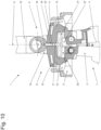
- the figures show a mop plate 1 with a base body 2, to which a first mop plate wing 3 and a second mop plate wing 4 are pivotably connected.
- the base body 2 is assigned a joint 5, here a universal joint, which can be connected to a handle.
- the mop plate wings 3, 4 can be reversibly fixed in a working position 6. In the working position 6, the two mop plate wings 3, 4 are essentially aligned in one plane.
- a foot pedal 23 By operating a foot pedal 23, the mop plate wings 3, 4 can be pivoted from the working position 6 into a wringing position 7.
- the wiping plate 1 and the wiping plate wings 3, 4 have a top side and a bottom side that forms the wiping surface.
- the bottom sides of the first wiping plate wing 3 and the second wiping plate wing 4 move towards each other when the wiping plate wings 3, 4 are pivoted from the working position 6 into the wringing position 7.
- the two bottom sides of the two wiping plate wings 3, 4 are opposite each other.
- the foot pedal 23 is pivotably mounted on the first mop plate wing 3 and is designed such that the foot pedal 23 fixes the second mop plate wing 4 in the working position 6.
- the foot pedal 23 is further designed such that the second mop plate wing 4 pivots relative to the first mop plate wing 3 when the foot pedal 23 is actuated.
- the foot pedal 23 is connected in an articulated manner to the first mop plate wing 3, wherein the foot pedal 23 has a first free end protruding from the first mop plate wing 3, which forms the actuating section of the foot pedal 23. Furthermore, the foot pedal 23 has a second free end protruding in the direction of the second mop plate wing 4, which forms the locking section of the foot pedal 23.
- the foot pedal 23 has two projections 28, 29, which are associated with the locking section.
- the two projections 28, 29 are designed as Spring elements are formed and in the working position 6 are assigned to the underside of the second wiper plate wing 4.
- the two projections 28, 29 rest there with elastic preload.
- the second wiper plate wing 4 has projecting elements 26 which are designed such that the second wiper plate wing 4 together with elements 26 surrounds the base body 2 in a U-shape.
- Holding elements 31 are formed from the foot pedal 23, which engage over the elements 26 of the second wiper plate wing 4 and thereby, together with the projections 28, 29, fix the wiper plate wings 3, 4 in the working position 6.
- the holding elements 31 move away from the second mop plate wing 4 and release the second mop plate wing 4 for pivoting.
- the two projections 28, 29 press against the underside of the second mop plate wing 4 and thereby pivot the second mop plate wing 4 relative to the first mop plate wing 3 by actuating the foot pedal 23.
- the first wiping plate wing 3 and the second wiping plate wing 4 each have a toothing, whereby the teeth of the toothing engage with each other.
- both wiping plate wings 3, 4 pivot simultaneously relative to the base body 2.
- both wiping plate wings 3, 4 are located below the base body 2, or in a straight line to the handle, the joint 5 and the base body 2.
- the first wiper plate wing 3, the second wiper plate wing 4 and the foot pedal 23 are positively locked in the working position 6.
- the base body 2, the wiper plate wings 3, 4 and the joint 5 are made of injection-moldable plastic.
- the underside of the wiper plate wings 3, 4 is provided with a structure in the form of ribs 24.
- the ribs 24 enable a high local surface pressure of the mop cover on the floor to be cleaned. This improves the cleaning performance.
- the mop plate wings 3, 4 are provided with a device 25 for attaching a mop cover.
- this consists of recesses which are provided in the edge areas of the narrow sides of the mop plate wings 3, 4 and serve to accommodate push buttons of a mop cover.
- the mop cover is firmly connected to the mop plate 1 even in the wringing position 7, so that the mop cover can be wrung out in a wringing device while hanging from the mop plate 1.
- the base body 2 is assigned a fixing device 8 for locking the joint 5, which fixes the joint 5 in the wringing position 7 along the longitudinal axis 9 of the joint 5.
- the projecting elements 26 of the second mop plate wing 4 pivot in the direction of the joint 5.
- the joint 5 is blocked and cannot pivot in the direction of the elements 26.
- the elements 26 are assigned stop elements 32 which increase the contact area between the elements 26 and the joint 5.
- the elements 26 form part of the fixing device 8 and limit the mobility of the joint 5 in the pivoting direction pointing towards the main sides of the mop plate wings 3, 4.
- the joint 5 is designed as a universal joint and has a first joint body 15 and a second joint body 16.
- the first joint body 15 is pivotably arranged on the base body 2.
- the second joint body 16 is pivotably arranged on the first joint body 15, wherein the pivot axis between the first joint body 15 and the second Joint body 16 is aligned transversely to the pivot axis between first joint body 15 and base body 2, so that a universal joint is formed.
- the first joint body 15 receives a spring needle 17, which projects through a longitudinal opening 18 made in the first joint body 15.
- the second joint body 16 has a recess 19, which is congruent with the longitudinal opening 18 of the first joint body 15 when the second joint body 16 is aligned relative to the first joint body 15 in the direction of the longitudinal axis 9.
- the spring needle 17 has a needle section 20 which is arranged in the longitudinal opening 18 and has a spring section 21 which is arranged in a transverse opening 22 which is made in the first joint body 15 and is open in the direction of the base body 2.
- the mop plate wings 3, 4 When the mop plate wings 3, 4 are pivoted from the working position 6 into the wringing position 7, the mop plate wings 3, 4 come into contact with the spring section 21 via an intermediate element 27, which in turn presses the needle section 20 through the longitudinal opening 18 in the direction of the recess 19 of the second joint body 16. If the joint 5 is aligned with the longitudinal axis 9, the needle section 20 is pressed into the recess 19 so that the first joint body 15 and the second joint body 16 are fixed to one another along the longitudinal axis 9.
- the needle section 20 rests against the second joint body 16 with pre-tension and the needle section 20 automatically presses itself into the recess 19 when both joint bodies 15, 16 are finally aligned along the longitudinal axis 9. If the wiper plate wings 3, 4 are brought from the wringing position 7 into the working position 6, the wiper plate wings 3, 4 move away from the intermediate element 27 and the pre-tension of the spring section 21 on the needle section 20 decreases, thereby causing the needle section 20 to automatically move out of the recess 19.
- Two laterally projecting projections 10, 11 are formed from the joint 5, which rest on essentially semicircular sliding surfaces 12, 13 formed from the base body 2.
- the sliding surfaces 12, 13 have a plateau 14, wherein the plateau 14 is designed such that a step is formed at the transition between the curved sliding surface 12, 13 and the plateau 14. If the joint 5 is aligned at an angle to the longitudinal axis 9 during cleaning work, the projections 10, 11 rest on the circular sections of the sliding surfaces 12, 13. If the joint 5 is now pivoted in the direction of the longitudinal axis 9, the projections 10, 11 on the sliding surfaces 12, 13 move in the direction of the plateau 14, wherein the projections 10, 11 are deformed after reaching the step. This increases the resistance against further pivoting of the joint 5, so that the wiping plate 1 does not fold over during cleaning.
- Figure 1 shows the wiping plate 1 in the working position 6 in the front view.
- Figure 2 shows the wiping plate 1 in the working position 6 in plan view.
- Figure 3 shows the wiper plate 1 in the working position 6 in the bottom view.
- a cover can be seen in the bottom view, which covers the foot pedal 23 on the underside. This protects the foot pedal 23 from unwanted interventions via the underside.
- Figure 4 shows the wiping plate 1 in the working position 6 in side view. In this side view, the first wiping plate wing 3 with foot pedal 23 is shown.
- Figure 5 shows the wiper plate 1 in the working position 6 in another side view. In this side view, the second wiper plate wing 4 is shown.
- Figure 6 shows the wiping plate 1 in the working position 6 in a spatial representation.
- Figure 7 shows the wiping plate 1 in the wringing position 7 in a side view.
- the first wiping plate wing 3 with foot pedal 23 is shown.
- the elements 26 of the second wiping plate wing 4 can be seen.
- the elements 26 are pivoted in the direction of the joint 5.
- the projections 28, 29 of the foot pedal 23 can be seen, which are designed as spring tongues and in the working position 6 rest against the underside of the second wiping plate wing 4 with pre-tension.
- the stop elements 32 can be seen, which increase the contact area between the elements 26 and the joint 5.
- Figures 8 and 9 show details of the wiping plate 1 in the wringing position 7.
- the stop elements 32 as well as the sliding surfaces 12, 13 and the plateau 14 with the formed step can be seen.
- Figure 10 shows the wiping plate 1 in the wringing position 7 in the partial view.
- Figure 11 shows the wiper plate 1 in the working position 6, with the area around the foot pedal 23 shown in section. In this position, the holding elements 31 of the foot pedal 23 overlap the elements 26 of the second wiper plate wing 4. The projections 28, 29 of the foot pedal 23 rest against the underside of the elements 26 of the second wiper plate wing 4 with pre-tension.
- Figure 12 shows the wiper plate 1 according to Figure 11 , whereby the foot pedal 23 is actuated.
- the holding elements 31 are spaced from the second mop plate wing 4 and the second mop plate wing 4 is released for pivoting.
- the projections 28, 29 press against the Underside of the elements 26 of the second mop plate wing 4 and thereby move the second mop plate wing 4 and, via the toothing, also the first mop plate wing 3 out of the working position 6. If the foot pedal 23 is then released, the mop plate wings 3, 4 can no longer lock themselves in place and when the mop plate 1 is lifted, the mop plate wings 3, 4 pivot into the wringing position 7.
Landscapes
- Cleaning Implements For Floors, Carpets, Furniture, Walls, And The Like (AREA)
- Hinges (AREA)
Applications Claiming Priority (2)
| Application Number | Priority Date | Filing Date | Title |
|---|---|---|---|
| DE102018112821.5A DE102018112821A1 (de) | 2018-05-29 | 2018-05-29 | Wischplatte |
| PCT/EP2019/062569 WO2019228817A1 (de) | 2018-05-29 | 2019-05-16 | Wischplatte |
Publications (3)
| Publication Number | Publication Date |
|---|---|
| EP3801170A1 EP3801170A1 (de) | 2021-04-14 |
| EP3801170C0 EP3801170C0 (de) | 2024-07-24 |
| EP3801170B1 true EP3801170B1 (de) | 2024-07-24 |
Family
ID=66597583
Family Applications (1)
| Application Number | Title | Priority Date | Filing Date |
|---|---|---|---|
| EP19725110.1A Active EP3801170B1 (de) | 2018-05-29 | 2019-05-16 | Wischplatte |
Country Status (8)
| Country | Link |
|---|---|
| EP (1) | EP3801170B1 (pl) |
| CN (1) | CN112203570B (pl) |
| AU (1) | AU2019275870B2 (pl) |
| CA (1) | CA3101850C (pl) |
| DE (1) | DE102018112821A1 (pl) |
| ES (1) | ES2989317T3 (pl) |
| PL (1) | PL3801170T3 (pl) |
| WO (1) | WO2019228817A1 (pl) |
Families Citing this family (1)
| Publication number | Priority date | Publication date | Assignee | Title |
|---|---|---|---|---|
| PL4085814T3 (pl) * | 2021-05-06 | 2023-08-21 | Leifheit Ag | Płyta mopa |
Family Cites Families (10)
| Publication number | Priority date | Publication date | Assignee | Title |
|---|---|---|---|---|
| US5926896A (en) * | 1997-11-25 | 1999-07-27 | Rubbermaid Commercial Products Llc | Collapsible cleaning implement |
| DE19916556A1 (de) * | 1999-04-13 | 2000-10-19 | Set High Tech Ag Wolfhalden | Kreuzgelenk eines Bodenreinigungsgerätes |
| DE102005044507A1 (de) * | 2005-09-16 | 2007-03-22 | Leifheit Ag | Klappbare Wischerplatte |
| CN2887238Y (zh) * | 2005-12-25 | 2007-04-11 | 蔡理荣 | 一种拖把 |
| DE102007005973A1 (de) * | 2007-02-07 | 2008-08-14 | Leifheit Ag | Wischer |
| DE202011109652U1 (de) * | 2011-12-30 | 2012-02-09 | Axel R. Hidde | Mechanische Aufnahme für ein Reinigungsgerät |
| DE102012007525A1 (de) | 2012-04-17 | 2013-10-17 | Carl Freudenberg Kg | Wischerplatte mit zwei verschwenkbaren Plattenflügeln |
| CN203314910U (zh) * | 2013-05-20 | 2013-12-04 | 嘉兴捷顺旅游制品有限公司 | 一种可旋转甩干的平面拖把 |
| DE202014004630U1 (de) * | 2014-06-10 | 2014-08-22 | Sprintus Gmbh | Halter für Wischbezug |
| DE202017003155U1 (de) * | 2017-06-15 | 2017-07-11 | Sprintus Gmbh | Halter für einen Wischbezug |
-
2018
- 2018-05-29 DE DE102018112821.5A patent/DE102018112821A1/de not_active Ceased
-
2019
- 2019-05-16 CN CN201980035106.6A patent/CN112203570B/zh active Active
- 2019-05-16 CA CA3101850A patent/CA3101850C/en active Active
- 2019-05-16 PL PL19725110.1T patent/PL3801170T3/pl unknown
- 2019-05-16 EP EP19725110.1A patent/EP3801170B1/de active Active
- 2019-05-16 AU AU2019275870A patent/AU2019275870B2/en active Active
- 2019-05-16 ES ES19725110T patent/ES2989317T3/es active Active
- 2019-05-16 WO PCT/EP2019/062569 patent/WO2019228817A1/de not_active Ceased
Also Published As
| Publication number | Publication date |
|---|---|
| WO2019228817A1 (de) | 2019-12-05 |
| AU2019275870A1 (en) | 2020-11-26 |
| PL3801170T3 (pl) | 2025-03-10 |
| DE102018112821A1 (de) | 2019-12-05 |
| CA3101850C (en) | 2023-09-12 |
| CA3101850A1 (en) | 2019-12-05 |
| CN112203570A (zh) | 2021-01-08 |
| EP3801170C0 (de) | 2024-07-24 |
| AU2019275870B2 (en) | 2022-02-24 |
| ES2989317T3 (es) | 2024-11-26 |
| CN112203570B (zh) | 2022-09-06 |
| EP3801170A1 (de) | 2021-04-14 |
Similar Documents
| Publication | Publication Date | Title |
|---|---|---|
| DE202004002321U1 (de) | Positioniervorrichtung für eine Mehrsegment-Gleitschieneneinrichtung für Schubladen | |
| DE102012012134B4 (de) | Als Kindersitz ausgebildete Sicherheitssitzvorrichtung | |
| EP3318168B1 (de) | Moppbezughalter | |
| DE19908259A1 (de) | Wischmopplatte mit Schwenkkarretiereinrichtung | |
| EP2664704B1 (de) | Anlenk-Vorrichtung zum Anlenken eines Reibungs-Dämpfers an eine Waschmaschine | |
| DE4222948A1 (de) | Schmetterlings-bodenwischer | |
| WO2007118633A1 (de) | Wischgerät mit zwei gegeneinander klappbare wischflügel | |
| EP3801170B1 (de) | Wischplatte | |
| DE69907367T2 (de) | Befestigungsklammer, insbesondere für Handleuchte | |
| EP3801172B1 (de) | Wischplatte | |
| EP1188406B1 (de) | Wischer | |
| DE102019120132B4 (de) | Kugelpfannenvorrichtung für ein Gelenk | |
| EP2007265B1 (de) | Klappbare wischerplatte | |
| DE2819255A1 (de) | Waeschetrockner | |
| DE102013107316B3 (de) | Bodenwischer mit schwenkbaren Seitenflügeln | |
| DE102011008193B4 (de) | Vorrichtung zur Befestigung einer Handbrause an einer Wandstange | |
| DE2101047C3 (de) | Scheibenwischer | |
| DE7307119U (de) | Verriegelungsvorrichtung fuer einen verstellbaren kraftfahrzeugsitz | |
| DE202017003155U1 (de) | Halter für einen Wischbezug | |
| DE202004010429U1 (de) | Teleskopstiel | |
| DE102007032108B4 (de) | Greifzange für Haushaltszwecke | |
| DE202011002627U1 (de) | Vorrichtung zum Pressen eines Wischtuchs | |
| DE102006027284B4 (de) | Vorrichtung und Verfahren zum Reinigen von Böden | |
| DE4303993C2 (de) | Fußbodenwischer | |
| DE202011005690U1 (de) | Wischer |
Legal Events
| Date | Code | Title | Description |
|---|---|---|---|
| STAA | Information on the status of an ep patent application or granted ep patent |
Free format text: STATUS: UNKNOWN |
|
| STAA | Information on the status of an ep patent application or granted ep patent |
Free format text: STATUS: THE INTERNATIONAL PUBLICATION HAS BEEN MADE |
|
| PUAI | Public reference made under article 153(3) epc to a published international application that has entered the european phase |
Free format text: ORIGINAL CODE: 0009012 |
|
| STAA | Information on the status of an ep patent application or granted ep patent |
Free format text: STATUS: REQUEST FOR EXAMINATION WAS MADE |
|
| 17P | Request for examination filed |
Effective date: 20201111 |
|
| AK | Designated contracting states |
Kind code of ref document: A1 Designated state(s): AL AT BE BG CH CY CZ DE DK EE ES FI FR GB GR HR HU IE IS IT LI LT LU LV MC MK MT NL NO PL PT RO RS SE SI SK SM TR |
|
| AX | Request for extension of the european patent |
Extension state: BA ME |
|
| DAV | Request for validation of the european patent (deleted) | ||
| DAX | Request for extension of the european patent (deleted) | ||
| STAA | Information on the status of an ep patent application or granted ep patent |
Free format text: STATUS: EXAMINATION IS IN PROGRESS |
|
| 17Q | First examination report despatched |
Effective date: 20230131 |
|
| GRAP | Despatch of communication of intention to grant a patent |
Free format text: ORIGINAL CODE: EPIDOSNIGR1 |
|
| STAA | Information on the status of an ep patent application or granted ep patent |
Free format text: STATUS: GRANT OF PATENT IS INTENDED |
|
| INTG | Intention to grant announced |
Effective date: 20240227 |
|
| GRAS | Grant fee paid |
Free format text: ORIGINAL CODE: EPIDOSNIGR3 |
|
| GRAA | (expected) grant |
Free format text: ORIGINAL CODE: 0009210 |
|
| STAA | Information on the status of an ep patent application or granted ep patent |
Free format text: STATUS: THE PATENT HAS BEEN GRANTED |
|
| AK | Designated contracting states |
Kind code of ref document: B1 Designated state(s): AL AT BE BG CH CY CZ DE DK EE ES FI FR GB GR HR HU IE IS IT LI LT LU LV MC MK MT NL NO PL PT RO RS SE SI SK SM TR |
|
| REG | Reference to a national code |
Ref country code: GB Ref legal event code: FG4D Free format text: NOT ENGLISH |
|
| REG | Reference to a national code |
Ref country code: CH Ref legal event code: EP |
|
| REG | Reference to a national code |
Ref country code: IE Ref legal event code: FG4D Free format text: LANGUAGE OF EP DOCUMENT: GERMAN Ref country code: DE Ref legal event code: R096 Ref document number: 502019011739 Country of ref document: DE |
|
| U01 | Request for unitary effect filed |
Effective date: 20240724 |
|
| U07 | Unitary effect registered |
Designated state(s): AT BE BG DE DK EE FI FR IT LT LU LV MT NL PT SE SI Effective date: 20240731 |
|
| REG | Reference to a national code |
Ref country code: ES Ref legal event code: FG2A Ref document number: 2989317 Country of ref document: ES Kind code of ref document: T3 Effective date: 20241126 |
|
| PG25 | Lapsed in a contracting state [announced via postgrant information from national office to epo] |
Ref country code: NO Free format text: LAPSE BECAUSE OF FAILURE TO SUBMIT A TRANSLATION OF THE DESCRIPTION OR TO PAY THE FEE WITHIN THE PRESCRIBED TIME-LIMIT Effective date: 20241024 |
|
| PG25 | Lapsed in a contracting state [announced via postgrant information from national office to epo] |
Ref country code: GR Free format text: LAPSE BECAUSE OF FAILURE TO SUBMIT A TRANSLATION OF THE DESCRIPTION OR TO PAY THE FEE WITHIN THE PRESCRIBED TIME-LIMIT Effective date: 20241025 |
|
| PG25 | Lapsed in a contracting state [announced via postgrant information from national office to epo] |
Ref country code: IS Free format text: LAPSE BECAUSE OF FAILURE TO SUBMIT A TRANSLATION OF THE DESCRIPTION OR TO PAY THE FEE WITHIN THE PRESCRIBED TIME-LIMIT Effective date: 20241124 |
|
| PG25 | Lapsed in a contracting state [announced via postgrant information from national office to epo] |
Ref country code: HR Free format text: LAPSE BECAUSE OF FAILURE TO SUBMIT A TRANSLATION OF THE DESCRIPTION OR TO PAY THE FEE WITHIN THE PRESCRIBED TIME-LIMIT Effective date: 20240724 |
|
| PG25 | Lapsed in a contracting state [announced via postgrant information from national office to epo] |
Ref country code: RS Free format text: LAPSE BECAUSE OF FAILURE TO SUBMIT A TRANSLATION OF THE DESCRIPTION OR TO PAY THE FEE WITHIN THE PRESCRIBED TIME-LIMIT Effective date: 20241024 |
|
| PG25 | Lapsed in a contracting state [announced via postgrant information from national office to epo] |
Ref country code: RS Free format text: LAPSE BECAUSE OF FAILURE TO SUBMIT A TRANSLATION OF THE DESCRIPTION OR TO PAY THE FEE WITHIN THE PRESCRIBED TIME-LIMIT Effective date: 20241024 Ref country code: NO Free format text: LAPSE BECAUSE OF FAILURE TO SUBMIT A TRANSLATION OF THE DESCRIPTION OR TO PAY THE FEE WITHIN THE PRESCRIBED TIME-LIMIT Effective date: 20241024 Ref country code: IS Free format text: LAPSE BECAUSE OF FAILURE TO SUBMIT A TRANSLATION OF THE DESCRIPTION OR TO PAY THE FEE WITHIN THE PRESCRIBED TIME-LIMIT Effective date: 20241124 Ref country code: HR Free format text: LAPSE BECAUSE OF FAILURE TO SUBMIT A TRANSLATION OF THE DESCRIPTION OR TO PAY THE FEE WITHIN THE PRESCRIBED TIME-LIMIT Effective date: 20240724 Ref country code: GR Free format text: LAPSE BECAUSE OF FAILURE TO SUBMIT A TRANSLATION OF THE DESCRIPTION OR TO PAY THE FEE WITHIN THE PRESCRIBED TIME-LIMIT Effective date: 20241025 |
|
| PG25 | Lapsed in a contracting state [announced via postgrant information from national office to epo] |
Ref country code: RO Free format text: LAPSE BECAUSE OF FAILURE TO SUBMIT A TRANSLATION OF THE DESCRIPTION OR TO PAY THE FEE WITHIN THE PRESCRIBED TIME-LIMIT Effective date: 20240724 Ref country code: SM Free format text: LAPSE BECAUSE OF FAILURE TO SUBMIT A TRANSLATION OF THE DESCRIPTION OR TO PAY THE FEE WITHIN THE PRESCRIBED TIME-LIMIT Effective date: 20240724 |
|
| PG25 | Lapsed in a contracting state [announced via postgrant information from national office to epo] |
Ref country code: CZ Free format text: LAPSE BECAUSE OF FAILURE TO SUBMIT A TRANSLATION OF THE DESCRIPTION OR TO PAY THE FEE WITHIN THE PRESCRIBED TIME-LIMIT Effective date: 20240724 |
|
| PG25 | Lapsed in a contracting state [announced via postgrant information from national office to epo] |
Ref country code: SK Free format text: LAPSE BECAUSE OF FAILURE TO SUBMIT A TRANSLATION OF THE DESCRIPTION OR TO PAY THE FEE WITHIN THE PRESCRIBED TIME-LIMIT Effective date: 20240724 |
|
| PLBE | No opposition filed within time limit |
Free format text: ORIGINAL CODE: 0009261 |
|
| STAA | Information on the status of an ep patent application or granted ep patent |
Free format text: STATUS: NO OPPOSITION FILED WITHIN TIME LIMIT |
|
| 26N | No opposition filed |
Effective date: 20250425 |
|
| U20 | Renewal fee for the european patent with unitary effect paid |
Year of fee payment: 7 Effective date: 20250526 |
|
| PGFP | Annual fee paid to national office [announced via postgrant information from national office to epo] |
Ref country code: GB Payment date: 20250520 Year of fee payment: 7 Ref country code: ES Payment date: 20250612 Year of fee payment: 7 |
|
| PGFP | Annual fee paid to national office [announced via postgrant information from national office to epo] |
Ref country code: TR Payment date: 20250428 Year of fee payment: 7 |
|
| PGFP | Annual fee paid to national office [announced via postgrant information from national office to epo] |
Ref country code: PL Payment date: 20250430 Year of fee payment: 7 |
|
| REG | Reference to a national code |
Ref country code: CH Ref legal event code: H13 Free format text: ST27 STATUS EVENT CODE: U-0-0-H10-H13 (AS PROVIDED BY THE NATIONAL OFFICE) Effective date: 20251223 |
|
| PG25 | Lapsed in a contracting state [announced via postgrant information from national office to epo] |
Ref country code: CH Free format text: LAPSE BECAUSE OF NON-PAYMENT OF DUE FEES Effective date: 20250531 |
|
| PG25 | Lapsed in a contracting state [announced via postgrant information from national office to epo] |
Ref country code: MC Free format text: LAPSE BECAUSE OF FAILURE TO SUBMIT A TRANSLATION OF THE DESCRIPTION OR TO PAY THE FEE WITHIN THE PRESCRIBED TIME-LIMIT Effective date: 20240724 |