EP3799944B1 - Filterpatronen - Google Patents
Filterpatronen Download PDFInfo
- Publication number
- EP3799944B1 EP3799944B1 EP20203378.3A EP20203378A EP3799944B1 EP 3799944 B1 EP3799944 B1 EP 3799944B1 EP 20203378 A EP20203378 A EP 20203378A EP 3799944 B1 EP3799944 B1 EP 3799944B1
- Authority
- EP
- European Patent Office
- Prior art keywords
- media
- cartridge
- arrangement
- housing
- filter cartridge
- Prior art date
- Legal status (The legal status is an assumption and is not a legal conclusion. Google has not performed a legal analysis and makes no representation as to the accuracy of the status listed.)
- Active
Links
- 230000005764 inhibitory process Effects 0.000 claims description 21
- 238000011144 upstream manufacturing Methods 0.000 claims description 17
- 238000000034 method Methods 0.000 description 39
- 239000011324 bead Substances 0.000 description 35
- 239000000463 material Substances 0.000 description 29
- 238000009434 installation Methods 0.000 description 25
- 238000007789 sealing Methods 0.000 description 20
- 238000010276 construction Methods 0.000 description 17
- 239000000565 sealant Substances 0.000 description 15
- 230000002093 peripheral effect Effects 0.000 description 13
- 238000001914 filtration Methods 0.000 description 12
- 230000008569 process Effects 0.000 description 11
- 230000003993 interaction Effects 0.000 description 9
- 238000013459 approach Methods 0.000 description 8
- 239000000853 adhesive Substances 0.000 description 7
- 230000001070 adhesive effect Effects 0.000 description 7
- 239000000356 contaminant Substances 0.000 description 7
- 239000000835 fiber Substances 0.000 description 7
- 229920002994 synthetic fiber Polymers 0.000 description 6
- 239000012530 fluid Substances 0.000 description 5
- -1 polyethylene terephthalate Polymers 0.000 description 5
- 230000000712 assembly Effects 0.000 description 4
- 238000000429 assembly Methods 0.000 description 4
- 238000002485 combustion reaction Methods 0.000 description 4
- 239000002657 fibrous material Substances 0.000 description 4
- 239000007789 gas Substances 0.000 description 4
- 238000007689 inspection Methods 0.000 description 4
- 238000004519 manufacturing process Methods 0.000 description 4
- 230000013011 mating Effects 0.000 description 4
- 238000012986 modification Methods 0.000 description 4
- 230000004048 modification Effects 0.000 description 4
- 239000011347 resin Substances 0.000 description 4
- 229920005989 resin Polymers 0.000 description 4
- 229920001169 thermoplastic Polymers 0.000 description 4
- 230000007704 transition Effects 0.000 description 4
- 238000004804 winding Methods 0.000 description 4
- 230000008901 benefit Effects 0.000 description 3
- 229920002678 cellulose Polymers 0.000 description 3
- 239000001913 cellulose Substances 0.000 description 3
- 238000012512 characterization method Methods 0.000 description 3
- 238000003780 insertion Methods 0.000 description 3
- 230000037431 insertion Effects 0.000 description 3
- 229920003023 plastic Polymers 0.000 description 3
- 239000004033 plastic Substances 0.000 description 3
- 229920002635 polyurethane Polymers 0.000 description 3
- 239000004814 polyurethane Substances 0.000 description 3
- 230000001681 protective effect Effects 0.000 description 3
- 239000012209 synthetic fiber Substances 0.000 description 3
- 229920003043 Cellulose fiber Polymers 0.000 description 2
- 241001306288 Ophrys fuciflora Species 0.000 description 2
- 239000004698 Polyethylene Substances 0.000 description 2
- 239000004743 Polypropylene Substances 0.000 description 2
- 230000008859 change Effects 0.000 description 2
- 230000006835 compression Effects 0.000 description 2
- 238000007906 compression Methods 0.000 description 2
- 239000000428 dust Substances 0.000 description 2
- 230000000694 effects Effects 0.000 description 2
- 239000012943 hotmelt Substances 0.000 description 2
- 238000000465 moulding Methods 0.000 description 2
- 229920000728 polyester Polymers 0.000 description 2
- 229920000573 polyethylene Polymers 0.000 description 2
- 229920001155 polypropylene Polymers 0.000 description 2
- 238000012552 review Methods 0.000 description 2
- 230000035939 shock Effects 0.000 description 2
- 238000005728 strengthening Methods 0.000 description 2
- 238000012360 testing method Methods 0.000 description 2
- XLYOFNOQVPJJNP-UHFFFAOYSA-N water Substances O XLYOFNOQVPJJNP-UHFFFAOYSA-N 0.000 description 2
- 239000004677 Nylon Substances 0.000 description 1
- 239000004952 Polyamide Substances 0.000 description 1
- 239000004372 Polyvinyl alcohol Substances 0.000 description 1
- 229920000297 Rayon Polymers 0.000 description 1
- 240000006694 Stellaria media Species 0.000 description 1
- 238000005452 bending Methods 0.000 description 1
- 230000001010 compromised effect Effects 0.000 description 1
- 230000008602 contraction Effects 0.000 description 1
- 230000001419 dependent effect Effects 0.000 description 1
- 238000013461 design Methods 0.000 description 1
- 238000011161 development Methods 0.000 description 1
- 230000009477 glass transition Effects 0.000 description 1
- 238000010438 heat treatment Methods 0.000 description 1
- 230000007062 hydrolysis Effects 0.000 description 1
- 238000006460 hydrolysis reaction Methods 0.000 description 1
- 230000002401 inhibitory effect Effects 0.000 description 1
- 230000002452 interceptive effect Effects 0.000 description 1
- 230000001788 irregular Effects 0.000 description 1
- 238000002955 isolation Methods 0.000 description 1
- 239000007788 liquid Substances 0.000 description 1
- 239000012092 media component Substances 0.000 description 1
- 238000005065 mining Methods 0.000 description 1
- 239000000203 mixture Substances 0.000 description 1
- 238000012544 monitoring process Methods 0.000 description 1
- 229920001778 nylon Polymers 0.000 description 1
- 239000002985 plastic film Substances 0.000 description 1
- 229920002647 polyamide Polymers 0.000 description 1
- 239000004417 polycarbonate Substances 0.000 description 1
- 229920000515 polycarbonate Polymers 0.000 description 1
- 229920000139 polyethylene terephthalate Polymers 0.000 description 1
- 239000005020 polyethylene terephthalate Substances 0.000 description 1
- 229920000098 polyolefin Polymers 0.000 description 1
- 229920002689 polyvinyl acetate Polymers 0.000 description 1
- 239000011118 polyvinyl acetate Substances 0.000 description 1
- 229920002451 polyvinyl alcohol Polymers 0.000 description 1
- 229920000915 polyvinyl chloride Polymers 0.000 description 1
- 239000004800 polyvinyl chloride Substances 0.000 description 1
- 238000010248 power generation Methods 0.000 description 1
- 238000003825 pressing Methods 0.000 description 1
- 238000012797 qualification Methods 0.000 description 1
- 239000002964 rayon Substances 0.000 description 1
- 230000002829 reductive effect Effects 0.000 description 1
- 238000005096 rolling process Methods 0.000 description 1
- 239000012812 sealant material Substances 0.000 description 1
- WESJNFANGQJVKA-UHFFFAOYSA-M sodium;2,3-dichloro-2-methylpropanoate Chemical compound [Na+].ClCC(Cl)(C)C([O-])=O WESJNFANGQJVKA-UHFFFAOYSA-M 0.000 description 1
- 125000006850 spacer group Chemical group 0.000 description 1
- 238000003860 storage Methods 0.000 description 1
- 239000000126 substance Substances 0.000 description 1
- 239000004416 thermosoftening plastic Substances 0.000 description 1
- 238000002604 ultrasonography Methods 0.000 description 1
- 238000003466 welding Methods 0.000 description 1
Images


Classifications
-
- B—PERFORMING OPERATIONS; TRANSPORTING
- B01—PHYSICAL OR CHEMICAL PROCESSES OR APPARATUS IN GENERAL
- B01D—SEPARATION
- B01D46/00—Filters or filtering processes specially modified for separating dispersed particles from gases or vapours
- B01D46/24—Particle separators, e.g. dust precipitators, using rigid hollow filter bodies
-
- B—PERFORMING OPERATIONS; TRANSPORTING
- B01—PHYSICAL OR CHEMICAL PROCESSES OR APPARATUS IN GENERAL
- B01D—SEPARATION
- B01D46/00—Filters or filtering processes specially modified for separating dispersed particles from gases or vapours
- B01D46/0002—Casings; Housings; Frame constructions
- B01D46/0005—Mounting of filtering elements within casings, housings or frames
-
- B—PERFORMING OPERATIONS; TRANSPORTING
- B01—PHYSICAL OR CHEMICAL PROCESSES OR APPARATUS IN GENERAL
- B01D—SEPARATION
- B01D46/00—Filters or filtering processes specially modified for separating dispersed particles from gases or vapours
- B01D46/52—Particle separators, e.g. dust precipitators, using filters embodying folded corrugated or wound sheet material
- B01D46/521—Particle separators, e.g. dust precipitators, using filters embodying folded corrugated or wound sheet material using folded, pleated material
- B01D46/525—Particle separators, e.g. dust precipitators, using filters embodying folded corrugated or wound sheet material using folded, pleated material which comprises flutes
- B01D46/526—Particle separators, e.g. dust precipitators, using filters embodying folded corrugated or wound sheet material using folded, pleated material which comprises flutes in stacked arrangement
-
- B—PERFORMING OPERATIONS; TRANSPORTING
- B01—PHYSICAL OR CHEMICAL PROCESSES OR APPARATUS IN GENERAL
- B01D—SEPARATION
- B01D46/00—Filters or filtering processes specially modified for separating dispersed particles from gases or vapours
- B01D46/0084—Filters or filtering processes specially modified for separating dispersed particles from gases or vapours provided with safety means
- B01D46/009—Identification of filter type or position thereof, e.g. by transponders or bar codes
-
- B—PERFORMING OPERATIONS; TRANSPORTING
- B01—PHYSICAL OR CHEMICAL PROCESSES OR APPARATUS IN GENERAL
- B01D—SEPARATION
- B01D46/00—Filters or filtering processes specially modified for separating dispersed particles from gases or vapours
- B01D46/52—Particle separators, e.g. dust precipitators, using filters embodying folded corrugated or wound sheet material
-
- F—MECHANICAL ENGINEERING; LIGHTING; HEATING; WEAPONS; BLASTING
- F02—COMBUSTION ENGINES; HOT-GAS OR COMBUSTION-PRODUCT ENGINE PLANTS
- F02M—SUPPLYING COMBUSTION ENGINES IN GENERAL WITH COMBUSTIBLE MIXTURES OR CONSTITUENTS THEREOF
- F02M35/00—Combustion-air cleaners, air intakes, intake silencers, or induction systems specially adapted for, or arranged on, internal-combustion engines
- F02M35/02—Air cleaners
- F02M35/024—Air cleaners using filters, e.g. moistened
-
- B—PERFORMING OPERATIONS; TRANSPORTING
- B01—PHYSICAL OR CHEMICAL PROCESSES OR APPARATUS IN GENERAL
- B01D—SEPARATION
- B01D2265/00—Casings, housings or mounting for filters specially adapted for separating dispersed particles from gases or vapours
- B01D2265/02—Non-permanent measures for connecting different parts of the filter
- B01D2265/024—Mounting aids
- B01D2265/026—Mounting aids with means for avoiding false mounting
-
- B—PERFORMING OPERATIONS; TRANSPORTING
- B01—PHYSICAL OR CHEMICAL PROCESSES OR APPARATUS IN GENERAL
- B01D—SEPARATION
- B01D2271/00—Sealings for filters specially adapted for separating dispersed particles from gases or vapours
- B01D2271/02—Gaskets, sealings
- B01D2271/022—Axial sealings
Definitions
- the present disclosure relates to filter arrangements, typically for use in filtering air; such as intake air for internal combustion engines.
- the disclosure particularly relates to filter arrangements that use cartridges having opposite flow ends. Air cleaner arrangements and features; and, methods of assembly and use, are also described.
- Air streams can carry contaminant material such as dust and liquid particulate therein.
- contaminant material such as dust and liquid particulate therein.
- air flow streams to engines for example combustion air streams
- gas streams to gas turbine systems carry particulate contaminant therein that should be filtered.
- selected contaminant material be removed from (or have its level reduced in) the air.
- a variety of air filter arrangements have been developed for contaminant removal.
- a known air filter cartridge is for example disclosed in US 2015/013289 A1 . Improvements are sought.
- the claimed invention is defined in independent claim 1 and relates to an air filter cartridge. Preferred configurations of the claimed air filter cartridge are defined in dependent claims 2-15.
- air cleaner assemblies, housings, serviceable filter cartridges and features, components, and methods, relating thereto are disclosed.
- the features relate to systems that are configured to prevent an improper cartridge from appearing to be properly nested in an air cleaner housing, during servicing.
- a variety of approaches are described herein, that can be used independently or together to achieve a desired result.
- the filter cartridge would generally include a filter media therein, through which air and other gases pass, during a filtering operation.
- the media can be of a variety of types and configurations, and can be made from using a variety of materials.
- pleated media arrangements can be used in cartridges according to the principles of the present disclosure, as discussed below.
- the principles are particularly well adapted for use in situations in which the media is quite deep in extension between the inlet and outlet ends of the cartridge, but alternatives are possible. Also, the principles are often used in cartridges that relatively large cross-dimension sizes. With such arrangements, alternate media types to pleated media will often be desired.
- Fluted filter media can be used to provide fluid filter constructions in a variety of manners.
- One well known manner is characterized herein as a z-filter construction.
- the term "z-filter construction" as used herein, is meant to include (but not be limited) a type of filter construction in which individual ones of corrugated, folded or otherwise formed filter flutes are used to define (typically in combination with facing media) sets of longitudinal, typically parallel, inlet and outlet filter flutes for fluid flow through the media.
- Some examples of z-filter media are provided in U.S.
- One type of z-filter media utilizes two specific media components joined together, to form the media construction.
- the two components are: (1) a fluted (typically corrugated) media sheet or sheet section, and, (2) a facing media sheet or sheet section.
- the facing media sheet is typically non-corrugated, however it can be corrugated, for example perpendicularly to the flute direction as described in U.S. provisional 60/543,804, filed February 11, 2004 , and published as PCT WO 05/077487 on August 25, 2005 , incorporated herein by reference.
- the fluted media section and facing media section can comprise separate materials between one another. However, they can also be sections of the single media sheet folded to bring the facing media material into appropriate juxtaposition with the fluted media portion of the media.
- the fluted (typically corrugated) media sheet and the facing media sheet or sheet section together are typically used to define media having parallel flutes.
- the fluted sheet and facing sheet are separate and then secured together and are then coiled, as a media strip, to form a z-filter media construction.
- Such arrangements are described, for example, in U.S. 6,235,195 and 6,179,890 , each of which is incorporated herein by reference.
- some non-coiled sections or strips of fluted (typically corrugated) media secured to facing media are stacked with one another, to create a filter construction. An example of this is described in Fig. 11 of US 5,820,646 , incorporated herein by reference.
- strips of material comprising fluted sheet (sheet of media with ridges) secured to corrugated sheet, which are then assembled into stacks to form media packs, are sometimes referred to as "single facer strips,” “single faced strips,” or as “single facer” or “single faced” media.
- the terms and variants thereof, are meant to refer to a fact that one face, i.e., a single face, of the fluted (typically corrugated) sheet is faced by the facing sheet, in each strip.
- a strip of the fluted sheet/facing sheet (i.e., single facer) combination around itself, to create a coiled media pack is conducted with the facing sheet directed outwardly.
- Some techniques for coiling are described in U.S. provisional application 60/467,521, filed May 2, 2003 and PCT Application US 04/07927, filed March 17, 2004 , now published as WO 04/082795 , each of which is incorporated herein by reference.
- the resulting coiled arrangement generally has, as the outer surface of the media pack, a portion of the facing sheet, as a result.
- corrugated used herein to refer to structure in media, is often used to refer to a flute structure resulting from passing the media between two corrugation rollers, i.e., into a nip or bite between two rollers, each of which has surface features appropriate to cause corrugations in the resulting media.
- corrugation is however, not meant to be limited to such flutes, unless it is stated that they result from flutes that are by techniques involving passage of media into a bite between corrugation rollers.
- corrugated is meant to apply even if the media is further modified or deformed after corrugation, for example by the folding techniques described in PCT WO 04/007054, and published January 22, 2004 , incorporated herein by reference.
- Corrugated media is a specific form of fluted media.
- Fluted media is media which has individual flutes or ridges (for example formed by corrugating or folding) extending thereacross.
- Serviceable filter element or filter cartridge configurations utilizing z-filter media are sometimes referred to as "straight through flow configurations" or by variants thereof.
- the serviceable filter elements or cartridges generally have an inlet flow end (or face) and an opposite exit flow end (or face), with flow entering and exiting the filter cartridge in generally the same straight through direction.
- the term "serviceable” in this context is meant to refer to a media containing filter cartridge that is periodically removed and replaced from a corresponding fluid (e.g. air) cleaner.
- each of the inlet flow end (or face) and outlet flow end (or face) will be generally flat or planar, with the two parallel to one another. However, variations from this, for example non-planar faces, are possible.
- a straight through flow configuration (especially for a coiled or stacked media pack) is, for example, in contrast to serviceable filter cartridges such as cylindrical pleated filter cartridges of the type shown in U.S. Patent No. 6,039,778 , incorporated herein by reference, in which the flow generally makes a substantial turn as its passes into and out of the media. That is, in a 6,039,778 filter, the flow enters the cylindrical filter cartridge through a cylindrical side, and then turns to exit through an open end of the media (in forward-flow systems). In a typical reverse-flow system, the flow enters the serviceable cylindrical cartridge through an open end of the media and then turns to exit through a side of the cylindrical filter media. An example of such a reverse-flow system is shown in U.S. Patent No. 5,613,992 , incorporated by reference herein.
- z-filter media construction and variants thereof as used herein, without more, is meant to include, but not necessarily be limited to, any or all of: a web of corrugated or otherwise fluted media (media having media ridges) secured to (facing) media, whether the sheets are separate or part of a single web, with appropriate sealing (closure) to allow for definition of inlet and outlet flutes; and/or a media pack constructed or formed from such media into a three dimensional network of inlet and outlet flutes; and/or, a filter cartridge or construction including such a media pack.
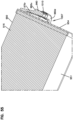
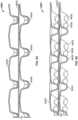
- FIG. 1 an example of media 1 useable in z-filter media construction is shown.
- the media 1 is formed from a fluted, in this instance corrugated, sheet 3 and a facing sheet 4.
- a construction such as media 1 is referred to herein as a single facer or single faced strip.
- the corrugated fluted or ridged sheet 3, Fig. 1 is of a type generally characterized herein as having a regular, curved, wave pattern of flutes, ridges or corrugations 7.
- wave pattern in this context, is meant to refer to a flute, ridge or corrugated pattern of alternating troughs 7b and ridges 7a.
- regular in this context is meant to refer to the fact that the pairs of troughs and ridges (7b, 7a) alternate with generally the same repeating corrugation (flute or ridge) shape and size.
- each trough 7b is substantially an inverse ridge for each ridge 7a.
- the term “regular” is thus meant to indicate that the corrugation (or flute) pattern comprises troughs (inverted ridges) and ridges with each pair (comprising an adjacent trough and ridge) repeating, without substantial modification in size and shape of the corrugations along at least 70% of the length of the flutes.
- the media 1 could be terminated, for example, between a pair comprising a ridge and a trough, or partially along a pair comprising a ridge and a trough.
- the media 1 depicted in fragmentary has eight complete ridges 7a and seven complete troughs 7b.
- the opposite flute ends may vary from one another. Such variations in ends are disregarded in these definitions, unless specifically stated. That is, variations in the ends of flutes are intended to be covered by the above definitions.
- the corrugation pattern is not the result of a folded or creased shape provided to the media, but rather the apex 7a of each ridge and the bottom 7b of each trough is formed along a radiused curve.
- a typical radius for such z-filter media would be at least 0.25 mm and typically would be not more than 3 mm.
- trough 7b is a concave region
- ridge 7a is a convex region.
- region 30 can be a straight segment, instead of a point, with curvature inverting at ends of the segment 30.
- a characteristic of the particular regular, wave pattern fluted (in this instance corrugated) sheet 3 shown in Fig. 1 is that the individual corrugations, ridges or flutes are generally straight, although alternatives are possible.
- straight in this context, it is meant that through at least 70%, typically at least 80% of the length, the ridges 7a and troughs (or inverted ridges) 7b do not change substantially in cross-section.
- the term "straight" in reference to corrugation pattern shown in Fig. 1 in part distinguishes the pattern from the tapered flutes of corrugated media described in Fig. 1 of WO 97/40918 and PCT Publication WO 03/47722, published June 12, 2003 , incorporated herein by reference.
- the tapered flutes of Fig. 1 of WO 97/40918 for example, would be a curved wave pattern, but not a "regular” pattern, or a pattern of straight flutes, as the terms are used herein.
- the media 1 has first and second opposite edges 8 and 9.
- edge 9 When the media 1 is formed into a media pack, in general edge 9 will form an inlet end or face for the media pack and edge 8 an outlet end or face, although an opposite orientation is possible.
- the various flutes 7 extend completely between the opposite edges 8, 9, but alternatives are possible. For example, they can extend to a location adjacent or near the edges, but not completely therethrough. Also, they can be stopped and started partway through the media, as for example in the media of US 2014/0208705 A1 , incorporated herein by reference.
- sealant bead 10 sealing the corrugated sheet 3 and the facing sheet 4 together.
- Bead 10 will sometimes be referred to as a "single facer" or “single face” bead, or by variants, since it is a bead between the corrugated sheet 3 and facing sheet 4, which forms the single facer (single faced) media strip 1.
- Sealant bead 10 seals closed individual flutes 11 adjacent edge 8, to passage of air therefrom (or thereto in an opposite flow).
- seal bead 14 In the media depicted in Fig. 1 , adjacent edge 9 is provided seal bead 14. Seal bead 14 generally closes flutes 15 to passage of unfiltered fluid therefrom (or flow therein in an opposite flow), adjacent edge 9. Bead 14 would typically be applied as media 1 is configured into a media pack. If the media pack is made from a stack of strips 1, bead 14 will form a seal between a back side 17 of facing sheet 4, and side 18 of the next adjacent corrugated sheet 3.
- bead 14 When the media 1 is cut in strips and stacked, instead of coiled, bead 14 is referenced as a “stacking bead.” (When bead 14 is used in a coiled arrangement formed from a long strip of media 1, it may be referenced as a “winding bead.”).
- seal material can be located differently, and added sealant or adhesive can even be avoided.
- the media can be folded to form an end or edge seam; or, the media can be sealed closed by alternate techniques such as ultrasound application, etc. Further, even when sealant material is used, it need not be adjacent opposite ends.
- the filter media 1 can be operated as follows. First, air in the direction of arrows 12, would enter open flutes 11 adjacent end 9. Due to the closure at end 8, by bead 10, the air would pass through the filter media 1, for example as shown by arrows 13. It could then exit the media or media pack, by passage through open ends 15a of the flutes 15, adjacent end 8 of the media pack. Of course operation could be conducted with air flow in the opposite direction.
- the parallel corrugations 7a, 7b are generally straight completely across the media, from edge 8 to edge 9.
- Straight flutes, ridges or corrugations can be deformed or folded at selected locations, especially at ends. Modifications at flute ends for closure are generally disregarded in the above definitions of "regular,” “curved” and “wave pattern.”
- the filter media is a relatively flexible material, typically a nonwoven fibrous material (of cellulose fibers, synthetic fibers or both) often including a resin therein, sometimes treated with additional materials.
- a nonwoven fibrous material of cellulose fibers, synthetic fibers or both
- it can be conformed or configured into the various corrugated patterns, without unacceptable media damage.
- it can be readily coiled or otherwise configured for use, again without unacceptable media damage.
- it must be of a nature such that it will maintain the required corrugated configuration, during use.
- the media contains a resin.
- the media can be heated to above the glass transition point of the resin. When the resin then cools, it will help to maintain the fluted shapes.
- the media of the corrugated (fluted) sheet 3 facing sheet 4 or both can be provided with a fine fiber material on one or both sides thereof, for example in accord with U.S. 6,673,136 , incorporated herein by reference.
- a fine fiber material on one or both sides thereof, for example in accord with U.S. 6,673,136 , incorporated herein by reference.
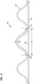
- z-filter media i.e., a z-filter media construction 40, utilizing a regular, curved, wave pattern corrugated sheet 43, and a non-corrugated flat sheet 44, i.e., a single facer strip is schematically depicted.
- the length D2 of the arcuate media for the corrugated flute 53, over the same distance D1 is of course larger than D1, due to the shape of the corrugated flute 53.
- the linear length D2 of the media 53 between points 50 and 51 will often be at least 1.2 times D1.
- D2 would be within a range of 1.2 - 2.0 times D1, inclusive.
- One particularly convenient arrangement for air filters has a configuration in which D2 is about 1.25 - 1.35 x D1.
- Such media has, for example, been used commercially in Donaldson Powercore TM Z-filter arrangements.
- Another potentially convenient size would be one in which D2 is about 1.4 - 1.6 times D1.
- the ratio D2/D1 will sometimes be characterized as the flute/flat ratio or media draw for the corrugated media.
- DCI A Flute: Flute/flat 1.52: 1;
- E Flute: Flute/flat 1.24: 1;
- X Flute: Flute/flat 1.29: 1;
- standard flute configurations from the corrugated box industry can be used to define corrugation shapes or approximate corrugation shapes for corrugated media. Comparisons above between the DCI A flute and DCI B flute, and the corrugation industry standard A and standard B flutes, indicate some convenient variations.
- FIG. 4 one example of a manufacturing process for making a media strip (single facer) corresponding to strip 1, Fig. 1 is shown.
- facing sheet 64 and the fluted (corrugated) sheet 66 having flutes 68 are brought together to form a media web 69, with an adhesive bead located therebetween at 70.
- the adhesive bead 70 will form a single facer bead 10, Fig. 1 .
- An optional darting process occurs at station 71 to form center darted section 72 located mid-web.
- the z-filter media or Z-media strip 74 can be cut or slit at 75 along the bead 70 to create two pieces or strips 76, 77 of z-filter media 74, each of which has an edge with a strip of sealant (single facer bead) extending between the corrugating and facing sheet.
- a strip of sealant single facer bead
- the edge with a strip of sealant would also have a set of flutes darted at this location.
- the z-filter media 74 before the z-filter media 74 is put through the darting station 71 and eventually slit at 75, it must be formed. In the schematic shown in Fig. 4 , this is done by passing a sheet of filter media 92 through a pair of corrugation rollers 94, 95. In the schematic shown in Fig. 4 , the sheet of filter media 92 is unrolled from a roll 96, wound around tension rollers 98, and then passed through a nip or bite 102 between the corrugation rollers 94, 95. The corrugation rollers 94, 95 have teeth 104 that will give the general desired shape of the corrugations after the flat sheet 92 passes through the nip 102.
- the sheet 92 After passing through the nip 102, the sheet 92 becomes corrugated across the machine direction and is referenced at 66 as the corrugated sheet.
- the corrugated sheet 66 is then secured to facing sheet 64. (The corrugation process may involve heating the media, in some instances.)
- the process also shows the facing sheet 64 being routed to the darting process station 71.
- the facing sheet 64 is depicted as being stored on a roll 106 and then directed to the corrugated sheet 66 to form the Z-media 74.
- the corrugated sheet 66 and the facing sheet 64 would typically be secured together by adhesive or by other means (for example by sonic welding).
- an adhesive line 70 is shown used to secure corrugated sheet 66 and facing sheet 64 together, as the sealant bead.
- the sealant bead for forming the facing bead could be applied as shown as 70a. If the sealant is applied at 70a, it may be desirable to put a gap in the corrugation roller 95, and possibly in both corrugation rollers 94, 95, to accommodate the bead 70a.
- Fig. 4 can be modified to provide for the tack beads 20, Fig. 1 , if desired.
- corrugation provided to the corrugated media is a matter of choice, and will be dictated by the corrugation or corrugation teeth of the corrugation rollers 94, 95.
- One useful corrugation pattern will be a regular curved wave pattern corrugation, of straight flutes or ridges, as defined herein above.
- the techniques may be applied with curved wave patterns that are not "regular," including, for example, ones that do not use straight flutes. Also, variations from the curved wave patterns shown, are possible.
- Fig. 4 shows, in cross-section, one of the flutes 68 after darting and slitting.
- a fold arrangement 118 can be seen to form a darted flute 120 with four creases 121a, 121b, 121c, 121d.
- the fold arrangement 118 includes a flat first layer or portion 122 that is secured to the facing sheet 64.
- a second layer or portion 124 is shown pressed against the first layer or portion 122.
- the second layer or portion 124 is preferably formed from folding opposite outer ends 126, 127 of the first layer or portion 122.
- two of the folds or creases 121a, 121b will generally be referred to herein as "upper, inwardly directed" folds or creases.
- the term “upper” in this context is meant to indicate that the creases lie on an upper portion of the entire fold 120, when the fold 120 is viewed in the orientation of Fig. 5 .
- the term “inwardly directed” is meant to refer to the fact that the fold line or crease line of each crease 121a, 121b, is directed toward the other.
- creases 121c, 121d will generally be referred to herein as “lower, outwardly directed” creases.
- the term “lower” in this context refers to the fact that the creases 121c, 121d are not located on the top as are creases 121a, 121b, in the orientation of Fig. 5 .
- the term “outwardly directed” is meant to indicate that the fold lines of the creases 121c, 121d are directed away from one another.
- upper and lower as used in this context are meant specifically to refer to the fold 120, when viewed from the orientation of Fig. 5 . That is, they are not meant to be otherwise indicative of direction when the fold 120 is oriented in an actual product for use.
- a regular fold arrangement 118 according to Fig. 5 in this disclosure is one which includes at least two "upper, inwardly directed, creases.” These inwardly directed creases are unique and help provide an overall arrangement in which the folding does not cause a significant encroachment on adjacent flutes.
- a third layer or portion 128 can also be seen pressed against the second layer or portion 124.
- the third layer or portion 128 is formed by folding from opposite inner ends 130, 131 of the third layer 128.
- the first layer or portion 122 is formed from an inverted ridge.
- the second layer or portion 124 corresponds to a double peak (after inverting the ridge) that is folded toward, and in preferred arrangements, folded against the inverted ridge.
- Coiled media or media pack arrangements can be provided with a variety of peripheral perimeter definitions.
- peripheral, perimeter definition and variants thereof, is meant to refer to the outside perimeter shape defined, looking at either the inlet end or the outlet end of the media or media pack.
- Typical shapes are circular as described in PCT WO 04/007054 .
- Other useable shapes are obround, some examples of obround being oval shape.
- oval shapes In general oval shapes have opposite curved ends attached by a pair of opposite sides. In some oval shapes, the opposite sides are also curved. In other oval shapes, sometimes called racetrack shapes, the opposite sides are generally straight. Racetrack shapes are described for example in PCT WO 04/007054 , and PCT application US 04/07927 , published as WO 04/082795 , each of which is incorporated herein by reference.
- Another way of describing the peripheral or perimeter shape is by defining the perimeter resulting from taking a cross-section through the media pack in a direction orthogonal to the winding access of the coil.
- Opposite flow ends or flow faces of the media or media pack can be provided with a variety of different definitions.
- the ends or end faces are generally flat (planer) and perpendicular to one another.
- one or both of the end faces include tapered, for example, stepped, portions which can either be defined to project axially outwardly from an axial end of the side wall of the media pack; or, to project axially inwardly from an end of the side wall of the media pack.
- the flute seals (for example from the single facer bead, winding bead or stacking bead) can be formed from a variety of materials.
- hot melt or polyurethane seals are described as possible for various applications.
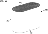
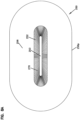
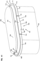
- a coiled media pack (or coiled media) 130 constructed by coiling a single strip of single faced media is depicted, generally.
- the particular coiled media pack depicted is an oval media pack 130a, specifically a racetrack shaped media pack 131.
- the tail end of the media, at the outside of the media pack 130 is shown at 131x. It will be typical to terminate that tail end along straight section of the media pack 130 for convenience and sealing.
- a hot melt seal bead or seal bead is positioned along that tail end to ensure sealing.
- the opposite flow (end) faces are designated at 132, 133. One would be an inlet flow face, the other an outlet flow face.
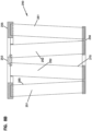
- Fig. 7 there is (schematically) shown a step of forming stacked z-filter media (or media pack) from strips of z-filter media, each strip being a fluted sheet secured to a facing sheet.
- single facer strip 200 is being shown added to a stack 201 of strips 202 analogous to strip 200.
- Strip 200 can be cut from either of strips 76, 77, Fig. 4 .
- application of a stacking bead 206 is shown, between each layer corresponding to a strip 200, 202 at an opposite edge from the single facer bead or seal. (Stacking can also be done with each layer being added to the bottom of the stack, as opposed to the top.)
- each strip 200, 202 has front and rear edges 207, 208 and opposite side edges 209a, 209b.
- Inlet and outlet flutes of the corrugated sheet/facing sheet combination comprising each strip 200, 202 generally extend between the front and rear edges 207, 208, and parallel to side edges 209a, 209b.
- opposite flow faces are indicated at 210, 211.
- the stacking bead 206 is positioned adjacent the upstream or inlet face 211; in others the opposite is true.
- the flow faces 210, 211 extend between opposite side faces 220, 221.
- the stacked media configuration or pack 201 shown being formed in Fig. 7 is sometimes referred to herein as a "blocked" stacked media pack.
- the term "blocked” in this context is an indication that the arrangement is formed to a rectangular block in which all faces are 90° relative to all adjoining wall faces.
- the stack can be created with each strip 200 being slightly offset from alignment with an adjacent strip, to create a parallelogram or slanted block shape, with the inlet face and outlet face parallel to one another, but not perpendicular to upper and bottom surfaces.
- the media or media pack will be referenced as having a parallelogram shape in any cross-section, meaning that any two opposite side faces extend generally parallel to one another.
- more than one stack can be incorporated into a single media pack.
- the stack can be generated with one or more flow faces that have a recess therein, for example, as shown in US 7,625,419 incorporated herein by reference.
- Figs. 8-8B An example of such alternate media arrangement or pack is depicted in Figs. 8-8B .
- the media of Figs. 8-8B is analogous to one depicted and described in DE 20 2008 017 059 U1 ; and as can sometimes found in arrangements available under the mark "IQORON" from Mann & Hummel.
- the media or media pack 250 comprises a first outer pleated (ridged) media loop 251 and a second, inner, pleated (ridged) media loop 252, each with pleat tips (or ridges) extending between opposite flow ends.
- the view of Fig. 8 is toward a media pack (flow) end 255.
- the end 255 depicted can be an inlet (flow) end or an outlet (flow) end, depending on selected flow direction.
- end 255 is an inlet flow end.
- the outer pleated (ridged) media loop 251 is configured in an oval shape, though alternatives are possible.
- a pleat end closure for example molded in place, is depicted closing ends of the pleats or ridges 251 at media pack end 255.
- Pleats, or ridges 252 are positioned surrounded by and spaced from loop 251, and thus pleated media loop 252 is also depicted in a somewhat oval configuration. In this instance, ends 252e of individual pleats or ridges 252p in a loop 252 are sealed closed. Also, loop 252 surrounds the center 252c that is closed by a center strip 253 of material, typically molded-in-place.
- end 255 is an inlet flow end
- air enters gap 265 between the two loops of media 251, 252.
- the air then flows either through loop 251 or loop 252, as it moves through the media pack 250, with filtering.
- loop 251 is configured slanting inwardly toward loop 252, in extension away from end 255. Also spacers 266 are shown supporting a centering ring 267 that surrounds an end of the loop 252, for structural integrity.
- FIG. 8A an end 256 of the cartridge 250, opposite end 255 is viewable.
- an interior of loop 252 can be seen, surrounding an open gas flow region 270.
- air that has entered media loop 251, Fig. 8 during filtering would generally pass around (over) an outer perimeter 256p of end 256.
- Fig. 8B a schematic cross sectional view of cartridge 250 is provided. Selected identified and described features are indicated by like reference numerals
- the cartridge 250 described is generally a cartridge which has media tips extending in a longitudinal direction between opposite flow ends 255, 256.
- the media pack 250 is depicted with an oval, in particular racetrack, shaped perimeter. It is depicted in this manner, since the air filter cartridges in many examples below also have an oval or racetrack shaped configuration. However, the principles can be embodied in a variety of alternate peripheral shapes.
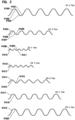
- FIGs. 9-12 some schematic, fragmentary, cross-sectional views are provided of still further alternate variations of media types that can be used in selected applications of the principles characterized herein. Certain examples are described in USSN 62/077,749, filed November 10, 2014 and owned by the Assignee of the present disclosure, Donaldson Company, Inc.
- each of the arrangements of Figs. 9-12 represents a media type that can be stacked or coiled into an arrangement that has opposite inlet and outlet flow ends (or faces), with straight through flow.
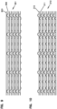
- FIG. 9 an example media arrangement 301 from USSN 62/077,749 is depicted, in which an embossed sheet 302 is secured to a non-embossed sheet 303, then stacked and coiled into a media pack, with seals along opposite edges of the type previously described for Fig. 1 herein.
- FIG. 10 an alternate example media pack 310 from USSN 62/077,749 is depicted, in which a first embossed sheet 311 is secured to a second embossed sheet 312 and then formed into a stacked or coiled media pack arrangement, having edge seals generally in accord with Fig. 1 herein.
- Edge seals can be conducted in either the upstream end or the downstream end, or in some instances both. Especially when the media is likely to encounter chemical material during filtering, it may be desirable to avoid a typical adhesive or sealant.
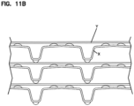
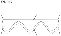
- Fig. 11A a cross-section is depicted in which the fluted sheet X has various embossments on it for engagement with the facing sheet Y. Again these can be separate, or sections of the same media sheet.
- Fig. 11B a schematic depiction of such an arrangement between the fluted sheet X and facing sheet Y is also shown.
- a fluted sheet 6402 is secured to a facing sheet 6403.
- the facing sheet 6403 may be a flat sheet.
- the media arrangement 6401 can then be stacked or coiled into a media pack, with seals along opposite edges of the type previously described for Fig. 1 herein.
- the flutes 6404 of fluted sheet 6402 have an undulating ridgeline including a series of peaks 6405 and saddles 6406.
- the peaks 6405 of adjacent flutes 6404 can be either aligned as shown in Figs. 64 and 65 or offset. Further the peak height and/or density can increase, decrease, or remain constant along the length of the flutes 6404.
- the ratio of the peak flute height to saddle flute height can vary from about 1.5 to 1 to 1.1 to about 1.
- the same media be used for the fluted sheet section and the facing sheet section.
- a different media can be desirable in each, to obtain different effects.
- one may be a cellulose media, while the other is a media containing some non-cellulose fiber. They may be provided with different porosity or different structural characteristics, to achieve desired results.
- the fluted sheet section or the facing sheet section can include a cellulose material, synthetic material, or a mixture thereof.
- one of the fluted sheet section and the facing sheet section includes a cellulose material and the other of the fluted sheet section and facing sheet section includes a synthetic material.
- Synthetic material(s) can include polymeric fibers, such as polyolefin, polyamide, polyester, polyvinyl chloride, polyvinyl alcohol (of various degrees of hydrolysis), and polyvinyl acetate fibers.
- Suitable synthetic fibers include, for example, polyethylene terephthalate, polyethylene, polypropylene, nylon, and rayon fibers.
- Other suitable synthetic fibers include those made from thermoplastic polymers, cellulosic and other fibers coated with thermoplastic polymers, and multi-component fibers in which at least one of the components includes a thermoplastic polymer.
- Single and multi-component fibers can be manufactured from polyester, polyethylene, polypropylene, and other conventional thermoplastic fibrous materials. The examples of Figs.
- the techniques characterized herein will preferably be applied when the media is oriented for filtering between opposite flow ends of the cartridge is media having flutes or pleat tips that extend in a direction between those opposite ends.
- the techniques characterized herein with respect to seal arrangement definition can be applied in filter cartridges that have opposite flow ends, with media positioned to filter fluid flow between those ends, even when the media does not include flutes or pleat tips extending in a direction between those ends.
- the media for example, can be depth media, can be pleated in an alternate direction, or it can be a non-pleated material.
- Air cleaner designs especially assemblies that use relatively deep filter media packs, for example using media in general accord with one or more of Figs. 6-12 , have proliferated.
- attention is directed to the air cleaners of Donaldson Company, Inc. the Assignee of the present disclosure sold under the trade designation "Powercore;” and, also, to the products of Mann & Hummel provided under the designation "IQORON.”
- air cleaner assemblies using such media packs can be incorporated in a wide variety of original equipment (on road trucks, buses; off road construction equipment, agriculture and mining equipment, etc.) on a global basis. Service parts and servicing are provided by a wide range of suppliers and service companies.
- the filter cartridge selected for servicing be an appropriate one for the air cleaner of concern.
- the air cleaner is a critical component in the overall equipment. If servicing is required to occur more frequently than intended, the result can be added expense, downtime for the equipment involved and lost productivity. If the servicing is not done with a proper part, there may be risk of equipment failure or other problems.
- the proper cartridge for the air cleaner of concern and equipment of concern is generally a product of: product engineering/testing by the air cleaner manufacturer; and, specification/direction/testing and qualification by the equipment manufacturer and/or engine manufacturer.
- Servicing in the field may involve personnel selecting a part that appears to be similar to the one previously installed, but which is not a proper, rigorously qualified, component for the system involved.
- a mass air flow sensor is provided downstream from the filter cartridge and upstream from the engine, to monitor air flow characteristics and contaminant characteristics.
- minor modifications in media pack configuration and orientation can lead to fluctuations in mass air flow sensor operation.
- the features and techniques described herein can be provided to advantageously obtain this benefit.
- the equipment on which the air cleaner is positioned is subject to substantial vibration and shock during operation.
- the types of media packs described above in connection with Figs. 6-12 are often constructed relatively deep, i.e. with having depth of extension in the air flow direction of at least 50 mm and often at least 80 mm more, in many instances more than 100 mm.
- Such deep filter cartridges can load with substantial amounts of contaminant during use, and gain substantially in weight. Thus, they can be subject to significant vibration momenta during operation. It is desirable to provide features in the filter cartridge that help ensure stable positioning of the cartridge, avoidance of damage to the media (or media pack) in the event of movement, and avoidance of seal failure during such vibration and shock.
- the equipment may be subject to a wide variety of temperature ranges during storage and use. These can lead to expansion/contraction of materials relative to one another. It is desirable to ensure that the filter cartridge and air cleaner are constructed in such a manner that seal integrity is not compromised under these circumstances.
- the features and techniques described herein can be applied to address these concerns, as discussed below.
- a filter cartridge which solves the issues characterized herein above, but which also is configured such that the air cleaner housing will not properly close, if such a "faulty installation" has occurred, for example through use of a cartridge that appears to fit the housing, but does not have the proper sealing characteristics.
- the techniques described herein address this issue. They can be used in connection with the features of such arrangements as characterized in WO 2006/076479 ; WO 2006/076456 ; WO 2007/133635 ; WO 2014/210541 and/or 62/097,060, but they can be used independently as well. This will be understood from the following discussions.
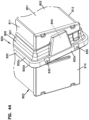
- Reference numeral 500, Fig. 13 generally indicates an air cleaner system or assembly including features in accord with the present disclosure.
- the air cleaner assembly 500 depicted includes a housing 501, in which a filter cartridge 502 is removably positioned. That is, the filter cartridge 502 is a serviceable component; i.e. it is removably positioned within interior 501i of housing 501.
- the housing 501 is generally configured in two housing sections, 503, 504, that are configured to be selectively separated or opened, for example along joint 501j to allow access for removal and replacement of cartridge 502.
- section 503 is a housing body component or assembly
- section 504 is an access cover component or assembly.
- one of the housing sections is mounted on equipment for use; and is not removed from this mounting during servicing.
- the housing cover component 504 is operated as an access cover, to allow opening access to air cleaner housing 501, to service cartridge 502.
- the housing 501 includes an air flow inlet arrangement 505 and a filtered air flow outlet or outlet arrangement 506.
- air to be filtered flows into the air cleaner assembly 500 through inlet arrangement 505. It passes through the cartridge 502 with filtering, and is then removed from the housing via outlet arrangement 506 to be directed to downstream equipment, for example to an engine, combustion air, intake.
- the inlet 505 is generally oriented to be upwardly directed in installation and outlet 506 to be generally directed somewhat orthogonal to the inlet direction.
- alternatives are possible.
- the airflow inlet arrangement 505 is in the access cover 504; and, the airflow outlet arrangement 506 is in the housing body 503. Alternatives are possible.
- precleaners can be used in association with the air cleaner assembly. Precleaners can be used with principles in accord with the present disclosure.
- section 504 is removably mounted on section 503 in the example depicted, by a fastener arrangement, in the example comprising bolts 507.
- a fastener arrangement in the example comprising bolts 507.
- alternate fastening arrangements including latches, can be used.
- the access cover housing section 504 can be completely removed from the housing body 503 during servicing.
- hinge mounts can be used, with principles described herein.
- an optional mounting pad arrangement is depicted for securing the air cleaner assembly 500 to equipment, such as a vehicle with which it would be used.
- the mounting pad arrangement 510 is positioned on housing section 503, since it is section 503 that will be anchored in place on the equipment during use. Alternatives are possible.
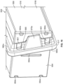
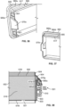
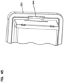
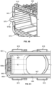
- FIG. 14 the air cleaner assembly 500 (of Fig. 13 ) is depicted with the housing section 504 (i.e. the access cover) fully removed.
- cartridge 502 can be seen positioned on housing section 503 as it would be when properly installed or when ready to be removed.
- an optional evacuator valve member 511 is shown "exploded" from the assembly 500. It would normally be included in the access cover 504 and is characterized below. Also, still referring to Fig 14 , fasteners or bolts 507 are shown where they would typically be mounted.
- a plurality of optional, spaced, perimeter receivers 515 positioned on the housing section 503 adjacent an open end thereof.
- the depicted receivers 515 are open, exterior, loops on the housing that are oriented to each receive one of a plurality of projections on the access cover 504, during attachment of the access cover 504 to the housing body 503.
- the housing 501 includes an optional projection/receiver arrangement between the two sections 503/504 that helps guide the section 504 to the section 503, as connection between the two occurs.
- This projection/receiver arrangement comprises a plurality of first members (see projections 536, Fig. 22 ) on one of the sections 503/504 and a plurality of second members 515 (e.g. receivers) on another of the sections 503/504.
- the receivers 515 are on the body section 503, but alternatives are possible.
- a mixed arrangement can be used with both projections and receivers being appropriately positioned on each of the housing components or sections 503, 504.
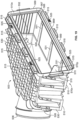
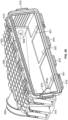
- the cartridge 502 is shown separated from the housing 501.
- the cartridge 502 generally comprises media 516 and a housing engagement arrangement 517 that extends around the media 516.
- the housing engagement arrangement 517 includes a housing seal member 518.
- the housing engagement arrangement 517 is configured to: properly orient the cartridge 502 on the housing section 503 during installation; provide for a seal of the cartridge 502 to the housing 501 for proper air cleaner assembly operation; and, to provide for support and cushioning of the cartridge 502 in the housing 501 during use.
- the housing engagement arrangement 517 is a molded-in-place component, which is preferred, but alternatives are possible.
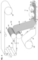
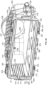
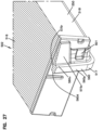
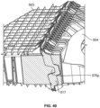
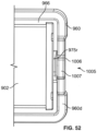
- FIG. 19 the housing section 503 is depicted, with the access cover 504 and cartridge 502 removed.
- Mounting pad arrangement 510 can be viewed, as can receivers 515. Also viewable in Fig. 19 are receivers 525 for the bolts 507, Fig 14 .
- an auxiliary port arrangement is provided that can be used to provide mounting of monitoring equipment, such as a restriction indicator, in the housing 501. Also viewable in Fig. 19 , is an auxiliary filtered air outlet 528.
- the auxiliary filtered air outlet 528 can allow for transport of filtered air to another location, besides the outlet 506, for example for operation of equipment such as a compressed air system and/or a brake system.
- the housing body 503 includes strengthening ridges, gussets and grid work 530 thereon, for structural integrity when the housing 501 is molded from a plastic.
- some internal, bottom, ribs are shown, against which the cartridge 502 can be positioned to slide or rest, when installed.
- a side end abutment is depicted. This can be used to engage with an end of the cartridge 502, if desired, during cartridge installation. It can be configured with a shape for projection/receiver interaction with the cartridge, if desired.
- Such an abutment/interaction is shown and described in WO 2007/044677 , incorporated herein by reference.
- Fig. 19 it is noted that the particular air cleaner assembly 501 depicted, is configured for use without a secondary or safety cartridge. It could be configured to receive a safety cartridge downstream from the main cartridge 502, if desired.
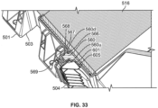
- seal surface 568 is shown, between inner rim 567 and outer rim 569.
- a seal member 560 on the cartridge 502 discussed below, is positioned pressed against seal surface 568 between the inner rim 567 and outer rim 569, for sealing.
- rib 568r can be seen projecting from seal surface 568. It will press into the seal material during sealing.
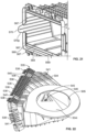
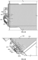
- FIG. 20 a second perspective view of housing section 503 is provided.
- Outlet 506 auxiliary port 526; auxiliary filtered air outlet port 528; receivers 515; fastener receivers 525 for bolts 507; abutment 532; seal surface 568; rib 568r; outer rim 569 and inner rib 567.
- the second housing section 504 in the example an access cover, is depicted.
- section 504 includes a plurality of tabs or perimeter projections 536 at least a portion of which are oriented to push into receivers 515, during installation.
- receivers 515 and projection arrangements 536 comprise a projection/receiver arrangement for engagement.
- the projection/receiver arrangement can be configured with a projection arrangement on the first section 503 and a receiver arrangement on the second section 504, or with portions of each on each.
- the section 504 also includes a plurality of perimeter receivers 540 for bolts or other fasteners during installation. Further, section 504 includes various grid work, ribs, and gussets 541 for strength and material integrity.
- This bottom drain, depression or recess 541 can be used for collection of water, and drainage of that water through drain aperture 546, during use.
- An evacuator valve member 511, Fig. 14 , and referenced above, can be positioned over an exterior of drain aperture 546 in to facilitate control of evacuation of such material.
- Such drain arrangements are known in air cleaner assemblies; see for example WO 2007/133635 incorporated herein by reference.
- a second view of the access cover or housing section 504 is depicted.
- some features previously characterized can also be seen such as, for example: a portion of air flow inlet arrangement 505 is viewable; as are interior 504i; recess 545; drain outlet 546; projections 536; and, bolt receivers 540.
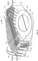
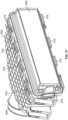
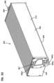
- the cartridge 502 as indicated previously, comprises media 516 and a housing engagement arrangement 517.
- the cartridge 502 has opposite flow ends 550, 551. During filtering, air passes through the filter cartridge in a "straight through" flow direction between the flow ends 550, 551. Typically, one of the flow ends will be an inlet flow end or flow face, and the other will be outlet flow end or flow face.
- flow end or face 550 is an inlet end for unfiltered air
- opposite flow end or face 551 is an outlet end for filtered air.
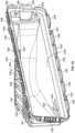
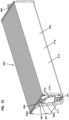
- cartridge 502 is shown in a view taken toward the flow outlet end 551.
- cartridges of the type of cartridge 502 will be characterized herein as configured for "straight through flow", or “axial flow” during use, referring to the fact that, generally, the cartridge 502 and the media 516 are configured so that air enters and leaves the cartridge 502, during filtering, with flow along the same direction. This can be accommodated with any of the media types referenced herein above, and variations.
- the example cartridge 502 depicted in Fig.15 generally has a "rectangular" perimeter shape in a plane perpendicular to the flow direction; and, as a result, a rectangular inlet end or face 550 and a rectangular outlet end or face 551. Alternate shapes are possible, including, for example, oval, and other perimeter shapes.
- the media 516 is configured to have an inlet end 516i adjacent the cartridge inlet end 550; and, an opposite outlet end 516o, not viewable in Fig. 15 , see Fig. 17 .
- the opposite surfaces or ends 516i, 516o are each depicted as generally planar, and each is in a plane generally perpendicular to a flow direction through the cartridge 502.
- the surfaces 516i, 516o can be slanted relative to the flow direction; and/or can be configured with variations therein, for example recesses or projections.
- variations of the type as found in WO 2007/133635 ; WO 2005/123222 ; and, WO 2007/044677 can be used with arrangements according to the present disclosure.
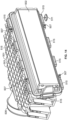
- the particular cartridge 502 depicted includes opposite side panels 554, 555 at opposite ends of the media 516.
- the opposite panels 554, 555 can be used with a variety of types of media characterized herein, to close opposite media ends 516x, 516y and to provide structural integrity. Of course, if an oval unit is used, or with alternate media, there may not be a need for such panels 554, 555.
- the use of opposite panels for closing various ones of the types of media characterized herein, above have been described, for example, in use with similar rectangular media packs in such references as WO 2005/123222 ; WO 2006/017790 ; WO 2006/076479 ; WO 2006/076456 ; and, WO 2007/133635 incorporated herein by reference.
- the panels 554, 555 can be (and typically and preferably will be) molded-in-place, but they can comprise preformed pieces that are secured over the media ends 516x, 516y with sealant.
- the particular panels 554, 555 depicted are molded-in-place, for example from a material such as a polyurethane that will seal the opposite ends 516x, 516y closed.
- the panels 554, 555 may have mold artifacts therein, such as artifacts 554x, Fig. 15 in panel 554, resulting from media stand-offs used in a mold during molding in place of the panel 554.
- the particular cartridge 502 depicted is shown having optional, opposite, cover pieces or panels 558, 559 thereon, extending across and closing the media pack 550 in extension between the opposite ends 516x, 516y, i.e. in extension between the opposite panels 554, 555.
- panels or cover pieces 558, 559 can be useful, for example, to protect the cartridge media 516 during handling. They can be molded-in-place, or they can comprise separate pieces attached to the media. In the example depicted, they comprise plastic sheets, for example comprising a polycarbonate plastic secured in place by being embedded in molded-in-place panels 554, 555. Alternatives are possible, such as a plastic net. When constructed in the manner shown, generally sealant will be provided between the panels 558. 559 and the media 516, to prevent a leak path through the cartridge 502.
- the covers 558, 559 on each surface can each be configured in two pieces, with a joint between them located underneath a molded-in-place arrangement 517, such that the molding-in-place of arrangement 517 can be, in part, directly to the media to help provide sealing.
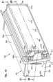
- the cartridge 502 includes housing engagement arrangement 517.
- the housing engagement arrangement 517 is generally a perimeter arrangement, i.e. it extends around a perimeter of a remainder of the cartridge 502.
- a portion of the housing engagement arrangement 517 generally comprises the housing seal member 518, for example a pinch seal flange 560.
- the housing seal flange 560 is generally positioned and configured to form a seal with the housing 501, when the cartridge 502 is properly installed.
- the particular housing seal member 518 depicted is a pinch seal flange 560 that is configured to be pinched between housing sections 503/504 when the housing 501 is closed.
- a critical surface for sealing of the housing seal arrangement 518 is a typically more downstream surface; i.e. a surface that would engage the housing 501, during use, at a location toward a clean air side of the system 501. In the example, this is a surface that is pressed into sealing with body 503. That surface is the more critical sealing surface, since it is on the downstream or clean air side of the seal 560. This referenced more critical seal surface is indicated generally in Fig 17 , at 560d.
- surface 560d is generally a flat, planar, featureless, surface in the example depicted. It can be varied (contoured) with features, for example contoured in accord with the disclosures of WO 201/210541 and/or USSN 62/097,060, incorporated herein by reference; and/or, in variations depicted and discussed below.
- the pinch seal member 560 includes an upstream pinch seal surface 560u, which is generally engaged by a flange or other structure on the access cover or housing section 504, during installation. This is where, in the example depicted, pressure is applied to the pinch seal member 560 during pinching, to ensure that the surface 560d seals against an appropriate surface 568 in the housing section 503. Sealing at surface 560u is less critical than at surface 560d, in the example depicted.
- seal member 560 located in extension between opposite pinch seal surfaces 560u, 560d, seal member 560 includes an outer, peripheral, surface 560p.
- the outer peripheral, surface 560p is generally configured to fit within selected housing features, such as rim 569, Fig. 19 , as needed for proper installation.
- region 560, between surfaces 560d, 560u can be varied. It will typically be at least 5 mm, and usually not more than about 20 mm, often it will be between 5 mm and 15 mm, but variations are possible.
- the example depicted seal surface 560d is configured and positioned with at least a portion that extends generally non-orthogonally to a flow direction through the cartridge media 516 (i.e. to a direction between ends 550, 551).
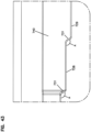
- the principles described herein can also be used with an alternate arrangement that does extend orthogonally, for example the alternate embodiment of Fig. 42 .
- the pinch seal 560 may sometimes be referred to as a slanted seal.
- the slant(s) can be defined as a seal slant angle, for example of at least 2° from the orthogonal.
- the slant angle would be generally at least 4°, usually at least 5° and often within the range of 5°-30°, for example 7°-20°.
- Slanted pinch seals usable with filter cartridges of the general type characterized herein are described for example in WO 2006/076456 and WO 2006/076479 , incorporated herein by reference.
- the cartridge 502 can be configured, in association with the housing 501, such that the cartridge 502 can only be installed in one rotational orientation relative to the housing 501. This can be advantageous in some instances, but is not required.
- the seal 560 extends non-orthogonally; but, generally, in extension between the panels 554 or 555, i.e., along the longer dimension of the depicted cartridge in Fig. 15 , the pinch seal member 560 generally extends along a path of extension perpendicular to the flow direction. This is typical, but alternatives are possible.
- the pinch seal member 560 when it extends across one of the sides 554, 555 of the rectangular configuration, the pinch seal member 560 generally extends along a straight path. While this is typical, alternatives are possible.
- the housing engagement arrangement 517 includes a base, support or web portion or member 565 which supports the pinch seal member 560 on a remainder of the cartridge 502.
- the particular support or web portion 565 depicted is molded integral with the peripheral pinch seal member 560, although alternatives are possible. Being molded integral with one another is preferred, as it avoids any need for a seal between the two.
- the housing seal member could be molded onto a not molded-in-place support, which is then attached to the cartridge. This may be convenient in some applications, but, again, typically a single molded-in-place piece will be preferred.
- the particular housing engagement arrangement 517 is molded-in-place on a remainder of the cartridge, as a peripheral component. This will be typical and preferred, as it helps ensure good secure sealing between the two, with good structural integrity.
- the portion of the housing engagement arrangement 517 that is in engagement with the remainder of the cartridge 502 is generally the web or support portion 565.
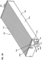
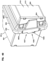
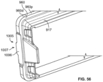
- Fig. 17 a view of the filter cartridge 502 taken toward the exit end 551, i.e. an end opposite that viewable in Fig. 15 . Attention is particularly directed to recess or groove 566.
- the recess or groove 566 is positioned between a portion of a pinch seal member 560 and a remainder of the cartridge 502.
- the groove 566 is a recess, receiver or groove positioned to receive, projecting therein, inner rim portion 567 of a housing 501, see Fig. 20 , during installation.
- the example depicted recess, groove or trough 560 extends completely, peripherally, around the cartridge 502 at a location between seal member 560 and the media 516.
- discontinuous recesses can be used, especially with a discontinuous rim 567.
- An example of this would be to provide a "trough” that extends with straight sections along each of the four sides, but which terminates as trough sections extend toward (i.e. into or around) at least one, and typically, each one, of the four corners. That is, in some instances the trough would have no corners.
- the recess 566 is optional in some applications.
- the housing section 503 includes an optional rim section 567, sized and configured project into recess 502 as installed.
- This rim 567 can be continuous or discontinuous, and provides a number of functions. First, it helps the cartridge 502 to snuggly rest. Secondly, it provides an isolation function between the pinch portion 560 and the cartridge body that tends to stabilize the cartridge body as it begins to load with dust and gain weight, and thus vibration momentum,.
- Such a trough or recess is generally described, for example in such references as WO 2006/076479 ; WO 2006/076456 ; WO 2006/017790 ; WO 2007/133635 ; USSN 62/097,060 ; and, WO 2014/210541 , incorporated herein by reference.
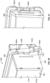
- seal surface 568 in the housing section 503, which is a surface against which seal surface 560u is compressed during sealing includes a central rib 568r therein, extending peripherally around the cartridge (or housing interior). This rib 568r will press into surface 560u in pinch seal member 560, during installation, to facilitate sealing. Also, seal surface 568 is positioned recessed between two walls, namely: rim 567 and outer rim or wall 569. This is typical.
- rib 568r is described in WO 2014/210541 .
- the rib 568r will typically be continuous, and project at least 0.5 mm, for example 0.5 to 3 mm, from immediately adjacent portions of the housing 501.
- a security installation inhibition arrangement among a filter cartridge and housing is described and provided, that will help ensure that unless a cartridge is a proper, authenticated, one with proper seal features, it will not be able to be positioned in an air cleaner housing such that the housing can be closed during installation. This will prevent a service provider from accidently installing a cartridge that appears to fit, but is not the proper, authenticated, cartridge for the system.
- servicing is often done in the field and may be done by service providers who have access to a variety of cartridges. It can be very important to ensure that the cartridge being installed is not a cartridge which appears to fit, but which is not the proper cartridge for the system.
- a manner in which this can be controlled is by using an arrangement involving engagement between the cartridge and the housing that prevents the cartridge from appearing to be fully and properly nested in sealing position, unless it is the proper cartridge.
- a feature or features that prevent the access cover from being able to be fully closed unless the cartridge is a proper, properly sealing, authenticated, cartridge appropriately inserted will sometimes be referred to as a "security, housing closure, inhibition arrangement" or by similar terms.
- housing section 503 which in the example is the downstream housing section, is provided with an open (inlet) end 513o having a projection arrangement 570 thereon, which comprises a first member of a security, housing closure, inhibition arrangement 570x.
- the projection arrangement 570 comprises a single projection 570p, although alternatives are possible.
- the projection 570p is located aligned with one of the shorter sides of the housing 501 (or section 503), but alternate locations are possible.
- projection arrangement 570 will engage that wrong cartridge and prevent it from being able to be fully positioned or nested in the housing section 503 and would thus prevent the access cover 504 from being able to be mounted.
- the cartridge 502 is a right or proper one, the cartridge 502 will have a second member of a projection receiver arrangement properly positioned to receive projection arrangement 570, and allow the cartridge 502 to be pushed into a proper, fully nested, position for the access cover 504 to then be installed.
- the particular projection arrangement 570 is located on the radially inner rim projection 567 that extends into a cartridge recess 566 ( Fig. 17 ), during installation.
- Alternatives are possible.
- the principal issue is to have the projection arrangement 570 sized and configured so that it will engage a portion of housing engagement arrangement 517 preventing full cartridge installation into housing section 503, unless a proper cartridge 502, properly positioned, used.
- projection arrangement 570 i.e. projection 570p can be seen from the inside.
- Strengthening ribs 571 are viewable.
- Fig. 21 an enlarged, fragmentary, perspective view is provided somewhat analogous to Fig. 20 , but at a greater angle.
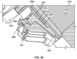
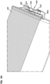
- FIG. 17 Attention is now directed to Fig. 17 , for an understanding of a portion of the example security, housing closure, inhibition arrangement 570x that is positioned on the cartridge 502.
- the cartridge 502 is depicted toward the outlet end 516o, i.e. toward the portion of the cartridge 502 that is received on or against the housing section 503 during installation.
- the seal arrangement 518 comprising pinch seal member 560 with downstream seal surface 560d, is viewable.
- the recess characterized above that receives rim 567 on the housing 501 is shown. It is noted that this recess 566 is sufficiently shallow so that it would be engaged in an inhibition manner (to installation) by projection arrangement 570, Fig.
- receiving pocket arrangement 575 comprises a single pocket 525r, since there is only one projection 570p, and only one possible proper installation orientation for the cartridge 502.
- Receiving pocket or receiver 580r is configured so that if the cartridge 502 is installed in the housing 503, projection arrangement 570 will not block the housing engagement arrangement 521 from full installation.
- the projection 570 will interfere with a housing engagement arrangement 517, preventing full cartridge installation, and ultimately, preventing full access cover closure.
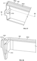
- FIG. 18 an enlarged fragmentary view is depicted showing the arrangement 575, i.e. receiver 575r.
- the particular example arrangement depicted includes a single projection 570p in the projection arrangement 570.
- cartridge 502 included a single mateable receiving member 575, i.e. pocket 575r.
- the receiving member 575 may comprise a plurality of pockets 575r, if desired; and, the projection arrangement 570 could comprise a plurality of projections 570p if desired.
- the resulting cartridge 502 can only be installed in a single rotational orientation due to the slanted seal 560d.
- the cartridge could theoretically be positioned in any one of two rotational orientations.
- FIG. 15 an exterior view is shown of an exterior portion of housing engagement component 517, under which the interior receiver or pocket 575r is located.
- the pocket 575r is characterized as a "interior pocket", when in the configuration shown, since it is positioned interiorly of portions 575x of the housing engagement arrangement 517, i.e., it is not on an exterior surface of the cartridge but rather is an interior arrangement. It is also a “closed” interior arrangement, in that it is not open in any fashion to the exterior, when used, but rather contains the projection member 570p. when used, in the manner shown.
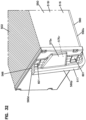
- the access cover 504 can be seen as having an internal recess or receiver arrangement 590 therein to provide clearance for receipt of this member 575x.
- FIG. 24 an enlarged fragmentary view of the receiver arrangement 590 and recess 590r are provided.
- FIG. 25 an exterior fragmentary view of a portion of the access cover 504 is provided.
- exterior portion 590x for the receiver arrangement 590 is shown.
- This exterior section 590x provides that one can easily observe in the assembled air cleaner 500, see Fig. 13 , that it is an air cleaner arrangement that has a security, housing closure, inhibition arrangement in accord with selected features of the present disclosure.
- the security, housing closure, inhibition arrangement described comprises a projection/receiver arrangement with: one member on the housing section 503 that comprises the downstream or clean air side; and, a second member on the cartridge 502.
- This type of arrangement will sometimes be characterized here as a "downstream" feature or arrangement, since the portion on the housing that engages the portion on the cartridge is positioned for insertion toward a downstream side of the seal arrangement 560.
- Alternatives are possible, as will be apparent from discussions below.
- portion of the security, housing closure, inhibition arrangement on the housing 503 i.e. the projection arrangement 570 or projection 570p is positioned radially inwardly from perimeter 560p of the housing pinch seal member 560, in particular radially inwardly from surface 560d.
- projection arrangement 570 projection 570p
- projection arrangement 570 is positioned radially inwardly from where sealing occurs between the associated housing component 503 and the seal member or arrangement 560 on the cartridge 502.
- radially inwardly in this context it is meant that the positioning is interiorly of a pattern defined by the seal service 560d, and/or perimeter 560p, i.e. toward a central flow direction axis of the cartridge 502.
- Such configurations will sometimes be characterized as a "radially interiorly engaging" arrangement, or by variants thereof. Alternatives to radially interiorly engagement arrangements are possible.
- projection arrangement 570 i.e. projection 570p
- projection 570p is positioned on the ridge 567 characterized above. This is typical and straightforward to assemble and use, but alternatives are possible.
- a security, housing closure, inhibition arrangement is characterized, which would prevent a cartridge from sufficiently nesting in a housing section 503, for the access cover 504 to be mounted, unless the cartridge included features for proper mating, such as receiver recess 575r.
- the particular, preferred, approach characterized is between the housing body and cartridge 502, so that even before an installer begins to put the access cover in position the installer would know that the cartridge was not a proper, authenticated, one that can be properly installed for use.
- a first member 600 of another security housing closure interference arrangement 600x is depicted, in this instance configured for use to ensure that unless a cartridge 502 installed in the housing body 503 is the right one, properly installed, the access cover 504 will interfere and not close.
- This arrangement can be used with arrangement 570x, or it can be used independently.
- the particular arrangement 600x depicted would correspond to an "upstream” arrangement since it is positioned to be engaged on an upstream side of the housing seal member 518. It is also an "open” and “exterior” arrangement, relative to arrangement 517 even though parts of it may be radially inside of surface 560u, the at least one arrangement is “exterior” because it is not contained by the seal 560.
- the member 600 depicted is at least one receiver or recess arrangement 601 extending radially inwardly in a portion of housing engagement arrangement 517, in the example in web 565.
- more than one recess 601 is depicted, but a single one can be used in some applications.
- Fig. 16 an enlarged fragmentary view of Fig. 15 is shown, and recesses 601 are viewable.
- the access cover 504 includes a projection arrangement indicated at 605 positioned to project into the recess arrangement 600.
- a projection arrangement indicated at 605 positioned to project into the recess arrangement 600.
- the approach is to size and position the engagement arrangement 600x such that interference will occur as a result of projections 605, unless an appropriate receiver arrangement 601, for engagement, is positioned on the cartridge 502.
- the second set of projections analogous to projections 605 could be positioned along an opposite side of the access cover 502.
- FIG. 26 a cross-sectional view of cartridge 502 is provided. The cross section is taken through the housing engagement arrangement 517 at a location through the receiver 575r. In Fig. 27 an enlarged fragmentary view of this portion of the cartridge 516 is shown.
- Fig. 28 a cross sectional view through the air cleaner assembly is shown, indicating that seal surface 560u is pressed against housing surface 568 and rib 568r, between inner rim 567 and outer rim 569.
- Fig. 29 a fragmentary cross sectional view is depicted showing projection 570p, on rim 587, extending into receiver 575r. Also, the seal member 560 can be seen positioned between the access cover 504, housing body 503. Overlap between the member 560 and various ones of the housing sections 503, 504 indicate where compression would occur, and an approximate amount of that compression that can, if desired, be used. Alternatives are possible.
- Fig. 30 a second enlarged fragmentary view analogous to Fig. 29 is shown.
- rib 568r can be seen projecting into surface 560d on the seal arrangement.
- FIG. 31 a second cross sectional view of the cartridge 502 is shown.
- the cross section is through a portion of the housing engagement arrangement 517 that does not have the receiver 575r therein, but does include recess 601.
- FIG. 32 an enlarged fragmentary view of the portion of the cartridge 502 of Fig. 31 is shown. Again, it can be seen that the cross section is through an exterior receiver recess 601.
- FIG. 33 an enlarged cross sectional view of this portion of the air cleaner assembly is shown.
- Seal member 560 can again be seen compressed between sections 503, 504. Also, a portion 605 of the access cover 504 projecting into receiver recess 601 can be seen. Further, rim 567, at a location not including projection 570p, can be seen extending into the trough 566.
- Fig. 34 an alternate perspective view of that of Fig. 33 is shown, depicting similar features.
- rib 568r can be seen projecting into the seal member 560.
- FIG. 36 an enlarged fragmentary perspective view of a portion of the engagement arrangement 517 is shown separate from the cartridge 502.
- the one depicted would not typically be constructed in this manner, since it would be molded in place.
- the figure allows for inspection of selected features previously indicated.
- Fig. 37 an analogous view is shown, but of an interior. Here, recess 575r is viewable.
- Fig. 38 yet another cross sectional view is provided. Projection 570p can be seen projecting into recess 575r.
- FIG. 39 yet another cross sectional view of the air cleaner assembly in this region is shown, but in perspective.
- Fig. 40 a cross sectional view and the general plane of Fig. 39 is viewable. Projection 570p, projecting into and being surrounded by material of the molding 517 can be seen.
- a coiled arrangement such as shown in Fig. 6 .
- alternatives to rectangular arrangements are possible.
- the media pack has a generally oval configuration with one long cross-section axis and one short cross-section axis; and, in which the media pack can be configured from a coiled arrangement, for example as characterized in connection with Fig. 6 .
- the techniques characterized herein can be used in association with a seal arrangement that does not have a flat, planar, downstream seal surface, but rather has contouring, such as by features generally in accord with WO 2014/210541 .
- Figs. 41-43 an example of this is depicted in the context shown.
- a cartridge 700 comprising media 701 extending between first and opposite ends or faces 702, 703.
- a housing engagement arrangement 710 is shown positioned on the cartridge 700 at a location extending peripherally around the media 701.
- the housing engagement arrangement comprises a seal portion 711 and a support or web portion 712. These portions can be formed generally analogous to similar portions in the previously described embodiments.
- the seal portion 711 comprises a pinch seal 715 having opposite pinch surfaces 716, 717.
- surface 716 would be the downstream or critical seal surface.
- the seal arrangement 715 also includes an outer peripheral surface 720.
- a housing interactive feature is shown in the housing engagement portion 710 and in particular in the seal member 711.
- This arrangement 724 is generally analogous to ones described in WO 2014/210541 and/or USSN 62/097,060 incorporated herein by reference.
- the example depicts a region 724 of distortion or contouring from flat in surface 716, and in particular a stepped region 725 comprising steps or projections (or projection sections) 728, 729 and 730. These would be sized, located and positioned to engage mating variations in the corresponding seal surface of the housing, during use. Said engagements are described, for example in WO 2014/210541 and/or USSN 62/097,060 incorporated herein by reference.
- the projection sections 728, 729 and 730 would have transition sections between them or between various ones of them and other portions of the seal surface 716, as indicated generally at 731.
- a variety of such stepped arrangements is possible, including multiple projections and multiple spaced projections.
- a maximum total extent of projection for region 725 would be at least about 5 mm, sometimes at least 10 mm, often within the range of 5-20 mm, but alternatives are possible.
- the outer peripheral rim 720 is modified and in this instance with a peripherally recessed portion 740.
- the peripherally recessed portion 740 can be in general accord with the descriptions of WO 2014/210541 and/or USSN 62/097,060 and can be varied therefrom. It can be provided in a single location or as multiple spaced sections. In the particular example, it is oriented in alignment with the same portion 724 of the seal arrangement 711 that has the stepped region s 725 therein. Alternatives are possible.
- the recess region 740 can be configured to be engaged by a housing feature in an appropriate system for installation.
- the housing seal arrangement comprising the housing engagement portion 710 and seal member 711 would be configured with a receiver recess or groove generally analogous to groove 566, Fig. 17 . This could be used analogously, to receive projecting therein a ridge or rim on a housing section.
- FIG. 41 an example is provided of how, for such a cartridge, a security, housing closure, interaction arrangement can be provided.
- attention is directed feature 750, where, internally, a receiver pocket 750r for a projection analogous to projection 370p would be positioned; and, to recesses 751, which could be used analogous to recesses 601 described above.
- the stepped region 725 could be located in overlap with one or both of the regions 750, 751 if desired.
- Fig. 42 a side elevational view of cartridge 700 is depicted.
- Fig. 43 an enlarged fragmentary view of a portion of Fig. 42 is shown.
- Transition regions 731 are viewable. Such transition regions 731 would typically extend over an angle A, relative to a plane perpendicular to the flow direction through the cartridge, of angle of about 35°-85°.
- inward recess region 740 can be viewed in Fig. 43 , which would usually correspond to an inward recess, at maximum of at least 2 mm, often at least 4 mm, and typically not more than 20 mm.
- a protective shield or sheath such as described in WO 2014/210541 and/or USSN 62/097,060 , incorporated herein by reference.
- a sheath can be used if desired.
- the housing engagement arrangement analogous to arrangement 710, Fig. 41 , is sometimes molded-in-place with a portion in direct contact with the media. Both practices can be applied with techniques in accord with the present disclosure, if desired.
- region 724 is shown with a peripheral recess 740, but the peripheral contouring could be a projection arrangement or both a projection and a recess arrangement if desired.
- the seal surface 716 is shown with projection arrangement 725, but it could alternately be a recess or a combination of recess and projection if desired.
- cartridge 800 is depicted in fragmentary view.
- the cartridge 800 comprises media 801 with opposite ends or flow surfaces 802, 803.
- Cartridge 800 includes a housing engagement arrangement 805 in the example depicted, molded-in-place in extension around a remainder of the cartridge.
- the example cartridge includes an end panel 810 (analogous to panel 554, Fig. 15 ) and protective covers or panels 811, 812, analogous to covers 559, 558, Fig. 15 .
- the example cartridge 800 depicted is meant to be analogous to cartridge 502, except as described below.
- the housing engagement arrangement 805 does comprise a pinch seal 820 and support web 821. Further pinch seal 820 includes opposite pinch seal surfaces 820d and 820u. It also has an outer periphery 820x.
- optional recesses 830 are depicted to operate analogously to optional recesses 601, Fig. 16 , with engagement with an access cover that would be appropriately configured. However, as noted by the differences, the recesses 830 can be positioned in, or partly in, the seal member 820, or partially in both the seal member 820 and the web 805.
- pocket 840 which would operate analogously to pocket 575r, Fig. 17 is depicted. It is noted, however, that for the embodiment of Fig. 45 , the pocket 840 does have a radial extension that extends at least partly into the seal member 820, unlike pocket 575r, Fig. 17 .
- Figs. 46-63 The example arrangement of Figs. 46-63 is depicted in an embodiment otherwise analogous to the embodiment of Figs. 13-40 . In this section, emphasis will be on the features demonstrating the points of differences. Generally analogous terms or depictions indicating analogous features are meant to indicate features with analogous functions.
- air cleaner assembly 900 comprising a housing 901, containing a removable, serviceable, filter cartridge 902.
- the housing 900 comprises separable housing sections 903, 904, securable by appropriate means such as a bolt fastener or similar fastener, not shown.
- the housing 901 includes an airflow inlet arrangement 905 and a filtered air outlet arrangement 906.
- the housing sections 903, 904 separate along region 907.
- FIG. 47 the air cleaner assembly 900 is depicted with the access cover 904 removed, thus allowing the viewing of cartridge 902, fully nested on housing section 903.
- Section 903 is depicted with receivers 915 thereon, analogous to receivers 515.
- cartridge 902 is depicted in perspective view.
- the cartridge 902 comprises media 916, with an inlet media end or face 916i and an opposite outlet media end or face 916o (not viewable).
- the cartridge 902 has an upstream flow end or face 950 and an opposite downstream end or face 951.
- the particular cartridge 902 includes opposite, in the example molded-in-place, panels 944, 945 (analogous to panels 544, 545) and also protective coverings or extensions 958, 959 (analogous to coverings 558, 559). These coverings (958, 959) are depicted extending between and embedded in the panels 944, 945.
- a housing engagement arrangement 917 is shown molded-in-place around a perimeter of the remainder of the cartridge 902.
- the housing engagement arrangement comprises a seal member 960 and a support or web section 965.
- FIG. 48 an interior recess or receiver pocket is shown at 975r, and, at 997, exterior recess arrangement is shown.
- contour region 1006 is shown in an outer perimeter 960p of seal member 960, and also a stepped contour section 1007 in downstream seal surface 906d (i.e. opposite surface 960u).
- contour arrangement 1006 is a recess, but it could alternatively be a projection or have aspects of both.
- contour section 1007 is depicted as projection section, but in alternate applications, it could be a recess section or have aspects of both.
- FIG. 49 an enlarged fragmentary view depicting region 1005 is shown.
- Fig. 50 a second fragmentary perspective view, taken generally of the same region 1005, but toward the downstream seal surface 960d.
- FIG. 51 an analogous view is shown to Fig. 50 , but at a different perspective, so that one can see interior receiving pocket 975r and trough or receiving groove 966.
- FIG. 52 another view is shown of similar portions of the cartridge 502, but here in plan view, for further inspection of receiver 975r, and trough 966.
- Fig. 53 a first cross sectional view of the cartridge is shown, taken generally along line 53-53, Fig. 48 .
- a cross section is through an exterior receiver 997.
- Fig. 54 a perspective view corresponding to the same cross section, in fragmentary, is shown, but taken generally toward surface 960d of the seal arrangement 960.
- a second cross sectional view is taken generally along line 55-55, Fig. 48 , but shown in fragmentary.
- the cross section is through the receiver pocket 975r, providing for inspection of this feature.
- the view is still generally toward downstream surface 960d and seal member 960. It is also through the largest step 1010 of the stepped region 1007.
- FIG. 56 an enlarged fragmentary view of the molded-in-place portion of the housing engagement arrangement 917 is shown.
- Fig. 57 an interior view of the same portion of arrangement 917 is shown.
- Fig. 58 a cross sectional view is taken at plane 58-58, Fig. 57 is shown.
- FIG. 59 a perspective view of the housing section 903 is depicted. Viewable are gridwork 930, outlet 906, auxiliary outlet 928, mounting pads 910, guide/slide ribs 931, receivers 915, projection arrangement 970 comprising projection 970p. Features generally analogous in appearance and location to those previously referenced above in variations discussed can be used.
- Fig. 60 a second perspective view shown fragmentary of the housing section 903 is viewable.
- Fig. 61 a plan view of housing section 903 is shown. Here a mating stepped recess section 968s for engagement with the stepped region 1007 is shown. Also seal rib 968r that presses into the seal member in use, is shown, in seal surface 968 between inner and outer rims 967and 969.
- FIG. 62 an exterior view of the housing section 903 taken toward the stepped region 968s is shown.
- Fig. 63 a perspective view of the section of Fig. 62 is shown.
- access cover 904 may be generally the same as access cover 504.
- Figs. 46-63 From the above description and inspection of Figs. 46-63 , it can be understood that the principles of the present application can be applied in which a contoured seal region, in accord, for example, with WO 2014/210541 and/or USSN 62/097,060 , incorporated herein by reference, can be applied in an arrangement which is otherwise analogous to Figs. 13-40 . Further it is depicted in alignment or overlap with a portion of the cartridge that also includes a receiving pocket 575r, i.e., a portion of the security, housing closure, inhibition arrangement. Of course it can be located not in such alignment if desired.
- example projection arrangements 570, 970 are described and depicted in various embodiments, as a portion or projection arrangement positioned on the housing body (503, 903, respectively) and projecting toward the access cover (504, 904, respectively). As explained, variations in these arrangements are possible.
- each projection e.g. 570, 570p, 970, 970p
- each projection will have a length of projection toward the other housing section 504, 904 of at least 20 mm, usually at least 30 mm and often at least 40 mm. This will help ensure adequate interference with an improper cartridge, for the intended operation.
- the maximum length of the projection (570p, 970p) is a matter of choice for the system of concern, once it is adequately long to ensure the desired interaction with an improper cartridge. Typically, the maximum lengths will not greater than 100 mm and often not greater than 80 mm in a variety of systems.
- the extent of projection of the projection arrangement 570, 970 is at least 15 mm further than the depth of any receiving groove 566, 966 in an associated cartridge (but for the receiving pocket 575r, 975r). Usually it is at least 25 mm deeper and often at least 35 mm deeper.
- the amount of extension of the projection arrangement 570, 970 is adequately far to extend axially beyond the upstream or opposite seal surface (560u, 960u), so that when a proper cartridge is installed, the projection arrangement extends well past the seal arrangement 560, 960 in extension toward the other housing piece or access cover 504, 904.
- this amount of extension is at least 15 mm, usually at least 25 mm; and, often at least 35 mm.
- the at least one receiving pocket 575r, 975r preferably extends at least 15 mm, usually at least 25 mm, often at least 35 mm further, toward cartridge end or flow face of the media pack than either seal surface.
- the end or flow face toward which the receiving pocket extends from the pinch seal will sometimes be referenced as an "associated" end or flow face.
- a variety of shapes for the individual projections 570p, 590p can be used.
- a base having a width of at least 15 mm, usually at least 25 mm, often at least 35 mm; and, a fee end or tip no greater in width that about 90% of the base; typically no greater than about 80% of the base is preferred.
- the projections 570p, 590p have blunt out tips or free ends, but alternatives are possible.
- the individual projections 570p, 590p are relatively thin in thickness (dimension from radial exterior to radial interior) even in the region of the ribs 571, Fig. 20 .
- a thickness no greater than 10 mm and typically no greater than 5 mm will be usable. Alternatives are possible.
- the side edges, Fig. 20 each extend at an obtuse angle (the same or different) from the base toward the free end. This is typical, but alternatives are possible.
- the individual projections 570p, 590p are oriented to project straight (in the flow direction) toward the access cover. This facilitates cartridge installation, but alternatives are possible.
- the projections 570p, 590p are located on and are integral with, rims 566 and 966, respectively. This is typical, but alternatives are possible.
- the projections 570p, 590p are located in overlap with a shorter dimension of a rectangular cartridge, or the curved end and shorter dimension of the oval cartridge. This is typical, but alternatives are possible.
- the projection arrangements can be orient aligned with a longer dimension instead of the sides. However, it is desirable to position them along a side that is located near the service provider in use, to help the service provider detect the interference interaction inhibiting closing, if an improper cartridge is being used.
- the member of the security housing closure inhibition arrangement on the filter cartridge is a receiving pocket or recess arrangement 575r, 975r, respectively.
- this pocket 575r, 975r is a deepened portion in engagement with a receiving groove 566, 966 that is somewhat shallow and otherwise extends all the way around the cartridge. This is typical, but alternatives are possible.
- the receiving pockets 575r, 975r are at least 10 mm deeper than an associated trough or recess 566, 966, usually, at least 20 mm deeper. Often, they are at least 200% deeper (3 times as deep), usually at least 400% deeper (5 times as deep) or more.
- each (575r, 975r) extends at least 10 mm toward an associated cartridge end face from the seal member 560, 960, (i.e. from either pinch seal surface) typically at least 20 mm and usually at least 30 mm or more, for example at least 35 mm or even at least 40 mm.
- each is at least 20 mm deep, usually at least 25 mm deep.
- the longest dimension of the receiving pockets 575r, 975r at the entrance thereto is at least 15 mm, usually at least 20 mm, and often greater 25 mm.
- it extends at least 10 mm further than each of the opposite surfaces (e.g. surfaces 560d, 560u) of the pinch seal portion, usually at least 20 mm further, often at least 25 mm further.
- the housing engagement portions 519, 917 comprise molded-in-place material. This is typical, but in some instances portions of these can be formed and preformed sections.
- the housing engagement portions are made as molded in placement arrangements, typically they are molded from the same material as is used for the housing seal arrangement, and are integral therewith.
- Such material for example, comprise a polyurethane or other foamed material, molded to an as-molded density of no greater than 0.48 g/cc, typically no greater than 0.35g/cc; and a hardness, Shore A, of no greater than 30, typically no greater than 20, often within the range of 10-20, inclusive.
- a polyurethane or other foamed material molded to an as-molded density of no greater than 0.48 g/cc, typically no greater than 0.35g/cc; and a hardness, Shore A, of no greater than 30, typically no greater than 20, often within the range of 10-20, inclusive.
- Alternatives, of course, are possible.
- exterior recesses 601, 901 are typically at least 3 mm deep in maximum relief from adjacent portion of the housing engagement arrangement, typically at least 7 mm deep, in maximum relief from at least some adjacent portions, sometimes 10 mm deep or more.
- each step individual has a maximum amount of projection relative to an immediately adjacent portion of the seal surface, of at least 2 mm, often at least 5 mm, usually within the range of 5-20 mm; and, the overall stepped region has a maximum amount of projection, relative to unstepped regions of the same seal surface, of at least 5 mm, usually at least 8 mm, and often within the range of 10-30 mm.
- Multiple projection regions and space projection regions around the perimeter can be used. These can be located along long sides, curved sides, opposite sides etc., as may be desired.
- a contour in a perimeter portion was described for example, in Fig. 42 at 740, and in Fig. 50 and 1006. These are depicted in overlap with a stepped region, but alternatives are possible.
- One or more contour regions can be used. When they are used, they are generally a maximum relief of at least 2 mm, usually at least 5 mm, relative to non-contoured portions of the outer perimeter of the seal member in which they are positioned.
- the arrangements depicted are generally are non-circular shapes for the media pack. Both rectangular perimeters and oval perimeters are shown.
- the features characterized herein are particularly desirable, when used with cartridges that have one relatively long width (cross) dimension by comparison to a shorter dimension taken perpendicular thereto.
- the media packs will have a longest width cross-dimension to maximum cross-dimension perpendicular thereto, of at least 1.5, usually at least 2 and often within the range of 2-5.
- the media pack will be relatively large, with a total width of at least 150 mm, for example at least 300 mm, and sometimes on the order of 400-800 mm. Often the dimension perpendicular will be not greater than 200 mm.
- Such large, wide, and shallow (perpendicular to width) media packs can be used to fit a variety of equipment. While the features characterized herein can be used with other sized and shaped media packs, they were developed to accommodate many field issues that are associated with such large media packs.
- the cartridge features can be provided in an asymmetric arrangement or a symmetric arrangement as desired.
- the symmetry or asymmetry can both be rotational with respect to an axis through the media pack in extension between flow ends; or, with respect to a plane through the media pack either: half-way along a longer cross-dimension and perpendicular thereto; or, half-way along a shorter cross-dimension and perpendicular thereto.
- Various features of the housing engagement arrangement can be made symmetrical or asymmetrical with respect to either of these concepts, as may be desired. Asymmetrical ones can be used to ensure that the cartridge can only be installed in a single orientation, if desired. Symmetrical arrangements can be used to allow the cartridge to be installed in more than orientation.
- the housing could be modified in general accord with these principles as well.
- the cartridge can be provided with a handle arrangement thereon adjacent the inlet side. Also, the cartridge and access cover can be configured for a different engagement to provide sealing pressure.
- the housing cannot be used with a cartridge that does not have appropriate features (member) for engagement with the member of the security, housing closure, inhibition, arrangement; the cartridge typically can be properly installed in a housing that does not have a member of the security, housing closure, inhibition arrangement, but is otherwise an analogous housing.
- the housing can be configured with a wide variety of variations from those depicted.
- the inlets and outlets can be alternately located and configured.
- the housing can be configured such that the cartridge is in a recessed portion of a housing section, rather than adjacent and in overlap with an outer edge thereof.
- the mating housing section would typically have a projection that extends into the housing sufficiently far, to push the seal arrangement into the desired seal engagement.
- the housing can be configured with a pre-cleaner as part of the housing, for example, as described in USSN 62/097,060 .
- the size of the housing can be varied greatly, in a variety of applications. However, the features are particularly well configured for use with a housing that a relatively large cartridge therein.
Claims (15)
- Luftfilterpatrone (502), umfassend:(a) ein Medienpaket (516) mit einem äußeren Umfang und gegenüberliegenden Strömungsflächen (516i, 516o); und,(b) ein Gehäuseeingriffselement (517), das das Medienpaket (516) umgibt; wobei das Gehäuseeingriffselement (517) eine Dichtungsanordnung aufweist, die umfasst: einen Quetschdichtungsabschnitt (560); und einen Dichtungsträgerabschnitt (565), wobei der Quetschdichtungsabschnitt (560) eine gegenüberliegende stromabwärtige Dichtungsfläche (560d) und stromaufwärtige Fläche (560u) aufweist;(c) ein Element einer Luftfilter-Sicherheits-Gehäuseverschluss-Sperrvorrichtung, das in dem Gehäuseeingriffselement (517) angeordnet ist;(i) wobei das Gehäuseeingriffselement (517) eine Taschenanordnung mit mindestens einer Aufnahmetasche (575) darin umfasst; und,(d) wobei das Gehäuseeingriffselement (517) so konfiguriert ist, dass es eine Aufnahmemulde (566) zwischen mindestens einem Teil des Gehäuseeingriffselements (517) und einem Rest der Filterpatrone (502) definiert; und,(i) wobei die mindestens eine Aufnahmetasche (575) des Gehäuseeingriffselements (517) eine tiefere Vertiefung als Teile der Aufnahmemulde (566) definiert,(e) dadurch gekennzeichnet, dass sich die tiefere Vertiefung über die stromaufwärtige Fläche (560u) der Quetschdichtungsfläche (560) hinaus erstreckt.
- Luftfilterpatrone (502) nach Anspruch 1, wobei:(a) die mindestens eine Aufnahmetasche (575) sich mindestens 10 mm in Richtung der Strömungsfläche über die stromaufwärtige Fläche (560u) des Quetschdichtungsabschnitts (560) hinaus erstreckt.
- Luftfilterpatrone (502) nach einem der Ansprüche 1-2, wobei:(a) die mindestens eine Aufnahmetasche (575) eine geschlossene Innentasche ist.
- Luftfilterpatrone (502) nach einem der Ansprüche 1-3, wobei:(a) die Taschenanordnung eine einzige Aufnahmetasche (575) umfasst.
- Luftfilterpatrone (502) nach einem der Ansprüche 1-4, wobei:(a) eine der Strömungsflächen eine stromaufwärtige Strömungsfläche (516i) ist; und,(b) die Aufnahmetasche (575) so konfiguriert ist, dass sie sich von einem benachbarten Quetschdichtungsabschnitt in Richtung der stromaufwärtigen Strömungsfläche (516i) erstreckt.
- Luftfilterpatrone (502) nach einem der Ansprüche 1-5, wobei:(a) sich die Aufnahmemulde (566) kontinuierlich um die Medien erstreckt oder sich die Aufnahmemulde (566) diskontinuierlich um die Medien erstreckt.
- Luftfilterpatrone (502) nach einem der Ansprüche 1-6, wobei:(a) die mindestens eine vertiefte Aufnahmetasche (575) in dem Gehäuseeingriffselement (517) mindestens dreimal so tief ist wie jeder angrenzende Abschnitt der Aufnahmemulde (566).
- Luftfilterpatrone (502) nach einem der Ansprüche 1-7, wobei:(a) die mindestens eine Aufnahmetasche (575) in dem Gehäuseeingriffselement (517) eine geschlossene Tasche mit einer Tiefe von mindestens 20 mm ist.
- Luftfilterpatrone (502) nach einem der Ansprüche 1-8, wobei:(a) die Aufnahmetasche (575) einen Eingang aufweist, der sich radial innerhalb des Quetschdichtungsabschnitts (560) befindet, und/oder die Aufnahmetasche (575) einen Eingang aufweist, der eine innere radiale Vertiefung in dem Quetschdichtungsabschnitt enthält.
- Luftfilterpatrone (502) nach einem der Ansprüche 1-9, wobei:(a) das Medienpaket (516) eine Abmessung zwischen den gegenüberliegenden Strömungsflächen (516i, 516o) von mindestens 50 mm hat und/oder die gegenüberliegenden Strömungsflächen (516i, 516o) eben sind.
- Luftfilterpatrone (502) nach einem der Ansprüche 1-10, wobei:(a) die gegenüberliegenden Strömungsflächen (516i, 516o) eine erste, längste Querabmessung von mindestens 150 mm haben.
- Luftfilterpatrone (502) nach einem der Ansprüche 1-11, wobei:(a) der Quetschdichtungsabschnitt (560) einen Abschnitt aufweist, der in einer Strömungsrichtung zwischen den gegenüberliegenden Strömungsflächen (516i, 516o) geneigt ist,(b) wobei sich der Quetschdichtungsabschnitt (560) vorzugsweise in einem Neigungswinkel von mindestens 2° erstreckt.
- Luftfilterpatrone (502) nach einem der Ansprüche 1-12, wobei:(a) der Quetschdichtungsabschnitt (560) eine flache, ebene Dichtungsfläche (560d) aufweist und/oder der Quetschdichtungsabschnitt (560) eine konturierte Dichtungsfläche (560d) aufweist.
- Luftfilterpatrone (502) nach einem der Ansprüche 1-13, wobei:(a) der Quetschdichtungsabschnitt (560) umfasst eine äußere Umfangsfläche (560p) mit mindestens einem konturierten Abschnitt darin.
- Luftfilterpatrone (502) nach einem der Ansprüche 1-14, wobei:(a) das Medienpaket (516) einen gegenüberliegenden Medienabschnitt umfasst, der an einem geriffelten Medienabschnitt befestigt ist, und/oder das Medienpaket (516) gefaltete Medien umfasst.
Priority Applications (1)
| Application Number | Priority Date | Filing Date | Title |
|---|---|---|---|
| EP23191579.4A EP4292690A1 (de) | 2015-03-02 | 2016-03-02 | Filterpatronen |
Applications Claiming Priority (4)
| Application Number | Priority Date | Filing Date | Title |
|---|---|---|---|
| US201562127166P | 2015-03-02 | 2015-03-02 | |
| US201562188861P | 2015-07-06 | 2015-07-06 | |
| PCT/US2016/020506 WO2016141097A2 (en) | 2015-03-02 | 2016-03-02 | Filter cartridges; air cleaner assemblies; housings; features; components; and, methods |
| EP16709657.7A EP3265209B1 (de) | 2015-03-02 | 2016-03-02 | Luftfilterpatrone und luftreinigeranordnung |
Related Parent Applications (2)
| Application Number | Title | Priority Date | Filing Date |
|---|---|---|---|
| EP16709657.7A Division-Into EP3265209B1 (de) | 2015-03-02 | 2016-03-02 | Luftfilterpatrone und luftreinigeranordnung |
| EP16709657.7A Division EP3265209B1 (de) | 2015-03-02 | 2016-03-02 | Luftfilterpatrone und luftreinigeranordnung |
Related Child Applications (1)
| Application Number | Title | Priority Date | Filing Date |
|---|---|---|---|
| EP23191579.4A Division EP4292690A1 (de) | 2015-03-02 | 2016-03-02 | Filterpatronen |
Publications (2)
| Publication Number | Publication Date |
|---|---|
| EP3799944A1 EP3799944A1 (de) | 2021-04-07 |
| EP3799944B1 true EP3799944B1 (de) | 2023-08-30 |
Family
ID=55524472
Family Applications (3)
| Application Number | Title | Priority Date | Filing Date |
|---|---|---|---|
| EP16709657.7A Active EP3265209B1 (de) | 2015-03-02 | 2016-03-02 | Luftfilterpatrone und luftreinigeranordnung |
| EP23191579.4A Pending EP4292690A1 (de) | 2015-03-02 | 2016-03-02 | Filterpatronen |
| EP20203378.3A Active EP3799944B1 (de) | 2015-03-02 | 2016-03-02 | Filterpatronen |
Family Applications Before (2)
| Application Number | Title | Priority Date | Filing Date |
|---|---|---|---|
| EP16709657.7A Active EP3265209B1 (de) | 2015-03-02 | 2016-03-02 | Luftfilterpatrone und luftreinigeranordnung |
| EP23191579.4A Pending EP4292690A1 (de) | 2015-03-02 | 2016-03-02 | Filterpatronen |
Country Status (10)
| Country | Link |
|---|---|
| US (4) | US10512868B2 (de) |
| EP (3) | EP3265209B1 (de) |
| JP (3) | JP6774949B2 (de) |
| KR (1) | KR102423166B1 (de) |
| CN (4) | CN107847843B (de) |
| AU (2) | AU2016226223B2 (de) |
| BR (2) | BR122022010023B1 (de) |
| PL (1) | PL3265209T3 (de) |
| RU (1) | RU2709693C2 (de) |
| WO (1) | WO2016141097A2 (de) |
Families Citing this family (20)
| Publication number | Priority date | Publication date | Assignee | Title |
|---|---|---|---|---|
| EP1771237B2 (de) | 2004-06-14 | 2018-10-10 | Donaldson Company, Inc. | Luftfilteranordnung und verfahren |
| CN100528288C (zh) | 2004-08-06 | 2009-08-19 | 唐纳森公司 | 空气过滤器装置;组件和方法 |
| ATE548102T1 (de) | 2005-01-13 | 2012-03-15 | Donaldson Co Inc | Luftfilteranordnung |
| MX2007008538A (es) | 2005-01-13 | 2007-09-07 | Donaldson Co Inc | Cartucho de filtro de aire y montaje de limpiador de aire. |
| CN101326358A (zh) | 2005-10-11 | 2008-12-17 | 唐纳森公司 | 空气过滤器结构,组件和方法 |
| EP3194048B1 (de) | 2014-09-15 | 2020-07-08 | Donaldson Company, Inc. | Filterpatrone und luftreinigeranordnung |
| BR122022010023B1 (pt) * | 2015-03-02 | 2023-03-07 | Donaldson Company, Inc | Cartucho de filtro de ar |
| US10974188B2 (en) | 2015-07-15 | 2021-04-13 | Baldwin Filters, Inc. | Filter with shield features |
| US10369508B2 (en) * | 2017-02-23 | 2019-08-06 | Baldwin Filters, Inc. | Filter with shield features |
| BR112018000732B1 (pt) | 2015-07-15 | 2022-09-20 | Baldwin Filters, Inc. | Elemento de filtro e armação para sustentar os primeiro e segundo painéis de meio de filtro |
| CN109689180B (zh) * | 2016-06-17 | 2022-12-02 | 唐纳森公司 | 空气滤清器组件和滤芯 |
| US20180161717A1 (en) | 2016-12-12 | 2018-06-14 | Donaldson Company, Inc. | Filter media, filter media packs, and filter elements |
| EP3675983B1 (de) | 2017-08-31 | 2023-04-26 | Donaldson Company, Inc. | Filterpatronen, luftreinigeranordnungen |
| MX2020013316A (es) | 2018-06-11 | 2021-02-22 | Donaldson Co Inc | Medios filtrantes, paquetes de medios filtrantes y elementos filtrantes. |
| KR102080874B1 (ko) * | 2018-07-06 | 2020-02-24 | (주)테슬라시스템 | 차량 기반 미세먼지 제거 서비스 방법 |
| CN114746163A (zh) | 2019-09-13 | 2022-07-12 | 唐纳森公司 | 空气过滤器系统、过滤袋组件、过滤袋 |
| US11498025B1 (en) * | 2019-12-04 | 2022-11-15 | Thursday Pools | Exhaust scrubber system and method |
| JP1694292S (de) * | 2020-09-25 | 2021-09-06 | ||
| US20220126227A1 (en) * | 2020-10-28 | 2022-04-28 | Baldwin Filters, Inc. | Gasket and frame assembly for air filter |
| CN114672368A (zh) * | 2022-03-28 | 2022-06-28 | 河南爱伊辣食品科技有限公司 | 一种料渣过滤结构及鲜椒酱用料油生产设备 |
Family Cites Families (114)
| Publication number | Priority date | Publication date | Assignee | Title |
|---|---|---|---|---|
| US399944A (en) | 1889-03-19 | Lantern-frame | ||
| US396098A (en) | 1889-01-15 | Combined strawberry-vine cutter and cultivator | ||
| US398046A (en) | 1889-02-19 | Garment fastener and support | ||
| US437401A (en) | 1890-09-30 | John h | ||
| US428128A (en) | 1890-05-20 | Cloth-piling machine | ||
| US1278508A (en) | 1917-07-14 | 1918-09-10 | Oscar C Roos | Radiotelegraph transmitting system. |
| US3401803A (en) * | 1965-12-06 | 1968-09-17 | Mine Safety Appliances Co | Filter formed from corrugated and flat sheets |
| GB1121896A (en) * | 1966-07-21 | 1968-07-31 | Gen Motors Ltd | Air filters |
| US3767053A (en) * | 1971-08-18 | 1973-10-23 | Aro Corp | Swivel filter |
| DE2743805C3 (de) * | 1977-09-29 | 1985-08-22 | Adolf Dipl.-Ing. 3060 Stadthagen Margraf | Vorrichtung mit einem filternden Abscheider |
| US4925561A (en) | 1988-03-31 | 1990-05-15 | Tsuchiya Mfg. Co., Ltd. | Composite planar and triangularly pleated filter element |
| JP2830080B2 (ja) | 1988-07-08 | 1998-12-02 | 株式会社デンソー | ▲ろ▼過エレメントおよびその製造方法 |
| JP3362453B2 (ja) | 1993-05-21 | 2003-01-07 | 株式会社デンソー | 濾過エレメント |
| US5843198A (en) | 1994-06-20 | 1998-12-01 | Walker; R. Karl | Air filter |
| US5613992A (en) | 1994-11-23 | 1997-03-25 | Donaldson Company, Inc. | Reverse flow air filter arrangement and method |
| DE19505583C5 (de) * | 1995-02-18 | 2014-10-02 | Mann + Hummel Gmbh | Filter, insbesondere zur Filtrierung der Luft für den Innenraum eines Fahrzeugs |
| DE29509806U1 (de) * | 1995-06-16 | 1995-08-24 | Hengst Walter Gmbh & Co Kg | Flüssigkeitsfilter |
| JPH09136536A (ja) * | 1995-11-16 | 1997-05-27 | Kansei Corp | 空気清浄器のフイルタ構体 |
| DE19654188C5 (de) | 1995-12-26 | 2010-09-23 | Toyoda Boshoku Corp., Kariya-shi | Filterelement und Verfahren für dessen Herstellung |
| US5772883A (en) | 1996-04-26 | 1998-06-30 | Donaldson Company, Inc. | Slanted inline filter |
| USD399944S (en) | 1996-04-26 | 1998-10-20 | Donaldson Company, Inc. | Conical filter |
| USD398046S (en) | 1996-04-26 | 1998-09-08 | Donaldson Company, Inc. | Combined filter element and frame therefor |
| US5820646A (en) | 1996-04-26 | 1998-10-13 | Donaldson Company, Inc. | Inline filter apparatus |
| US5895574A (en) | 1996-04-26 | 1999-04-20 | Donaldson Company, Inc. | Rolled liquid filter using fluted media |
| US5902364A (en) | 1996-04-26 | 1999-05-11 | Donaldson Company, Inc. | Conical filter |
| US5792247A (en) | 1996-04-26 | 1998-08-11 | Donaldson Company, Inc. | Integrated resonator and filter apparatus |
| DE69722933T2 (de) | 1996-04-26 | 2004-05-13 | Donaldson Co., Inc., Minneapolis | Gefaltetes filtermaterial |
| WO1998017490A1 (en) | 1996-10-24 | 1998-04-30 | Minnesota Mining And Manufacturing Company | A filter device for filtering a fluid |
| EP0941141B1 (de) | 1996-12-01 | 2003-09-03 | Clifford Roy Warner | Magnetische vorrichtung zur dekontaminierung |
| US6051042A (en) | 1997-09-12 | 2000-04-18 | Donaldson Company, Inc. | Air cleaner assembly |
| IT245039Y1 (it) * | 1998-03-25 | 2002-03-19 | Hiross Spa | Struttura di filtro per aria particolarmente per centrali di condizio-namento |
| JP3298052B2 (ja) | 1998-08-21 | 2002-07-02 | 豊田紡織株式会社 | エアフィルタ |
| US6235195B1 (en) | 1999-02-26 | 2001-05-22 | Donaldson Company, Inc. | Filter element incorporating a handle member |
| USD437401S1 (en) | 1999-02-26 | 2001-02-06 | Donaldson Company, Inc. | In-line air cleaner |
| US6190432B1 (en) | 1999-02-26 | 2001-02-20 | Donaldson Company, Inc. | Filter arrangement; sealing system; and methods |
| US6179890B1 (en) | 1999-02-26 | 2001-01-30 | Donaldson Company, Inc. | Air cleaner having sealing arrangement between media arrangement and housing |
| US6210469B1 (en) | 1999-02-26 | 2001-04-03 | Donaldson Company, Inc. | Air filter arrangement having first and second filter media dividing a housing and methods |
| DE19913181A1 (de) * | 1999-03-24 | 2000-09-28 | Mann & Hummel Filter | Filter mit topfförmigem Gehäuse und Rundfilterpatrone |
| DE19940610A1 (de) | 1999-08-27 | 2001-03-01 | Mann & Hummel Filter | Luftfilter |
| JP3837275B2 (ja) * | 2000-03-31 | 2006-10-25 | 本田技研工業株式会社 | エアクリーナ |
| JP3459224B2 (ja) * | 2000-06-02 | 2003-10-20 | 株式会社ケーヒン | 自動車用空調装置用ケーシング |
| US7476314B2 (en) * | 2000-08-11 | 2009-01-13 | Reid Roger P | Keyed system for connection of filter cartridge to filter holder |
| KR100916873B1 (ko) * | 2000-08-11 | 2009-09-09 | 로저 피. 리이드 | 필터 홀더에 필터 카트리지를 연결시키는 키 시스템 |
| US6673136B2 (en) | 2000-09-05 | 2004-01-06 | Donaldson Company, Inc. | Air filtration arrangements having fluted media constructions and methods |
| DE10137926B4 (de) * | 2001-08-07 | 2004-02-05 | Carl Freudenberg Kg | Kassettenfilter |
| CN1319624C (zh) | 2001-12-03 | 2007-06-06 | 唐纳森公司 | 介质体、采用波纹介质体板的过滤件、波纹板及制造方法 |
| JP2003287139A (ja) * | 2002-03-29 | 2003-10-10 | Uchiyama Mfg Corp | ガスケット |
| US6966940B2 (en) * | 2002-04-04 | 2005-11-22 | Donaldson Company, Inc. | Air filter cartridge |
| EP2269709B1 (de) * | 2002-05-09 | 2012-02-01 | Donaldson Company, Inc. | Luftfilter mit seitlichem Zugang |
| CN101306277B (zh) | 2002-07-10 | 2011-11-02 | 唐纳森公司 | 槽形过滤介体及其制造工艺 |
| ES2331124T3 (es) | 2002-12-11 | 2009-12-22 | Donaldson Company, Inc. | Medio filtrante z con sistemas de limpieza de flujo inverso y procedimientos. |
| KR20050098922A (ko) | 2003-02-11 | 2005-10-12 | 도널드선 컴파니 인코포레이티드 | 에어 크리너 배열과 서비스가능한 필터 구성 요소 및 방법 |
| DE602004027472D1 (de) | 2003-03-18 | 2010-07-15 | Donaldson Co Inc | Verbessertes verfahren zum wickeln von z-filtermedien |
| US7300486B1 (en) | 2003-04-02 | 2007-11-27 | Wix Filtration Corp Llc | Filter elements having injection molded thermoplastic seals and methods of making same |
| US7070641B1 (en) | 2003-12-03 | 2006-07-04 | Fleetguard, Inc. | Carbon media filter element |
| US20050130508A1 (en) | 2003-12-10 | 2005-06-16 | Sheng-Hsing Yeh | Structure of connector |
| WO2005077487A1 (en) | 2004-02-10 | 2005-08-25 | Donaldson Company, Inc. | Media arrangement; filter constructions; and, methods |
| EP2644247B1 (de) * | 2004-03-24 | 2018-07-11 | Donaldson Company, Inc. | Filterpatrone |
| CA2564883C (en) * | 2004-04-30 | 2013-12-17 | Paul R. Coulonvaux | Filter arrangements; housings; assemblies; and, methods |
| ATE486647T1 (de) * | 2004-06-08 | 2010-11-15 | Donaldson Co Inc | Z-filtermedienpackungsanordnung |
| EP1771237B2 (de) | 2004-06-14 | 2018-10-10 | Donaldson Company, Inc. | Luftfilteranordnung und verfahren |
| CN100528288C (zh) | 2004-08-06 | 2009-08-19 | 唐纳森公司 | 空气过滤器装置;组件和方法 |
| ATE492324T1 (de) * | 2004-08-25 | 2011-01-15 | Donaldson Co Inc | Luftreiniger und austauschbare filterpatronen |
| MX2007008538A (es) | 2005-01-13 | 2007-09-07 | Donaldson Co Inc | Cartucho de filtro de aire y montaje de limpiador de aire. |
| ATE548102T1 (de) | 2005-01-13 | 2012-03-15 | Donaldson Co Inc | Luftfilteranordnung |
| DE102005031058A1 (de) * | 2005-07-02 | 2007-01-04 | Mahle International Gmbh | Filterelement und ein zu dessen Aufnahme geeignetes Filtergehäuse |
| CN101326358A (zh) | 2005-10-11 | 2008-12-17 | 唐纳森公司 | 空气过滤器结构,组件和方法 |
| US7736410B2 (en) * | 2006-01-20 | 2010-06-15 | Donaldson Company, Inc. | Air cleaner configured for receipt of various sized filter cartridges; components thereof; and, methods |
| US7625419B2 (en) | 2006-05-10 | 2009-12-01 | Donaldson Company, Inc. | Air filter arrangement; assembly; and, methods |
| WO2007149561A2 (en) * | 2006-06-22 | 2007-12-27 | Donaldson Company, Inc. | Air cleaner arrangements; components thereof; and, methods |
| DE202006020287U1 (de) | 2006-11-07 | 2008-03-06 | Carl Freudenberg Kg | Filterelement mit tiefgezogenem Rahmen |
| CN102743931B (zh) | 2007-02-02 | 2015-12-02 | 唐纳森公司 | 空气过滤介质包、过滤元件、空气过滤介质及方法 |
| US8685130B2 (en) * | 2007-02-26 | 2014-04-01 | Donaldson Company, Inc. | Air filter arrangement; air cleaner assembly; and methods |
| CN103721492B (zh) * | 2007-06-14 | 2016-01-06 | 唐纳森公司 | 曲轴箱通风过滤器装置、部件和方法 |
| US8404029B2 (en) * | 2007-06-14 | 2013-03-26 | Donaldson Company, Inc. | Crankcase ventilation filter arrangments; components; and, methods |
| US8545589B2 (en) | 2007-06-26 | 2013-10-01 | Donaldson Company, Inc. | Filtration media pack, filter element, and methods |
| US8066791B2 (en) | 2007-07-20 | 2011-11-29 | Donaldson Company, Inc. | Air cleaner arrangements with internal and external support for cartridge; components; and, methods |
| US8292984B2 (en) | 2007-07-20 | 2012-10-23 | Donaldson Company, Inc. | Air cleaner arrangments with end support for cartridge; components; and, methods |
| RU2440300C2 (ru) | 2007-07-31 | 2012-01-20 | Селвин Корпорейт Лтд. | Перколяционная фильтрующая система |
| GB2452517B (en) | 2007-09-05 | 2012-04-25 | Visteon Global Tech Inc | Internal Combustion Engine Air Filtration |
| WO2009033040A1 (en) * | 2007-09-07 | 2009-03-12 | Donaldson Company, Inc. | Air filter assembly; components thereof; and, methods |
| AU2008320948B2 (en) * | 2007-11-15 | 2013-08-15 | Donaldson Company, Inc. | Air filter arrangements; assemblies; and, methods |
| CN100569337C (zh) * | 2008-04-22 | 2009-12-16 | 苏州科佳环境科技有限公司 | 无胶机械自密封式中效耐高温盒式过滤器 |
| DE102008027507A1 (de) * | 2008-06-10 | 2009-12-31 | Carl Freudenberg Kg | Filterelement mit einem 2-K-Rahmen |
| DE102009009066A1 (de) | 2009-02-16 | 2010-08-26 | Mann + Hummel Gmbh | Filtereinrichtung zur Filtration gasförmiger Fluide |
| CN102159297B (zh) * | 2008-07-22 | 2014-12-17 | 唐纳森公司 | 空气滤清器组件及其部件 |
| BRPI0917226A2 (pt) | 2008-08-06 | 2015-11-17 | Donaldson Co Inc | meios-z tendo fechamentos de canelura, métodos e equipamento |
| DE202008017059U1 (de) | 2008-12-23 | 2010-05-12 | Mann + Hummel Gmbh | Filtereinrichtung für Brennkraftmaschinen |
| US8464842B2 (en) | 2009-02-17 | 2013-06-18 | Goodrich Corporation | Brake wear measurement system and method |
| US8915985B2 (en) | 2009-03-31 | 2014-12-23 | Donaldson Company, Inc. | Air cleaner, components thereof, and methods |
| US8061530B2 (en) | 2009-04-09 | 2011-11-22 | Cummins Filtration Ip, Inc. | Filtration sealing system |
| DE102009048412B3 (de) * | 2009-10-06 | 2011-02-10 | Mann+Hummel Gmbh | Filtersystem und Filterelement zur Filtrierung von Fluiden |
| DE102010014277B4 (de) * | 2009-10-12 | 2020-03-12 | Mann+Hummel Gmbh | Filtervorrichtung und Hauptfilterelement für eine Filtervorrichtung |
| CN102906379B (zh) * | 2010-05-13 | 2016-06-29 | 唐纳森公司 | 发动机曲轴箱通风过滤器组件 |
| DE102010038297A1 (de) | 2010-07-22 | 2012-01-26 | Chemische Fabrik Budenheim Kg | Lebensmittelzubereitung mit Schmelzkäse |
| CN103282638B (zh) * | 2011-01-11 | 2017-02-08 | 曼·胡默尔有限公司 | 空气清洁器组件和空气过滤元件 |
| DE102011011595A1 (de) | 2011-02-17 | 2012-08-23 | Mann + Hummel Gmbh | Filterelement |
| DE102011077710A1 (de) | 2011-06-17 | 2012-12-20 | Mahle International Gmbh | Ringfilterelement |
| DE102011078057A1 (de) | 2011-06-24 | 2013-01-10 | Mahle International Gmbh | Plattenfilterelement |
| JP6075654B2 (ja) * | 2011-06-30 | 2017-02-08 | ドナルドソン カンパニー,インコーポレイティド | 空気/油分離装置アセンブリ、部品及び方法 |
| WO2013104791A1 (de) | 2012-01-13 | 2013-07-18 | Mann+Hummel Gmbh | Luftfilterelement mit haltegeometrie |
| CN104039419B (zh) | 2012-01-13 | 2017-02-08 | 曼·胡默尔有限公司 | 带有保持几何结构的空气过滤元件 |
| WO2013104790A1 (de) | 2012-01-13 | 2013-07-18 | Mann+Hummel Gmbh | Luftfilterelement mit haltegeometrie |
| DE102012005530A1 (de) * | 2012-03-21 | 2013-09-26 | Mann+Hummel Gmbh | Verfahren zur Herstellung eines mit einem Dichtungsteil versehenen Filterelements |
| WO2013139992A1 (de) * | 2012-03-23 | 2013-09-26 | Mann+Hummel Gmbh | Filterelement und luftfilter |
| US20140208705A1 (en) | 2013-01-25 | 2014-07-31 | Baldwin Filters, Inc. | Mutli-Pass Fluted Filter |
| DE102013003753A1 (de) * | 2013-03-06 | 2014-09-11 | Mann + Hummel Gmbh | Filter, Filterelement und Filtergehäuse |
| DE112014003011T5 (de) * | 2013-06-28 | 2016-03-10 | Donaldson Company, Inc. | Filtereinsätze, Luftreinigeranordnungen, Gehäuse, Merkmale, Komponenten und Verfahren |
| DE102014009887A1 (de) * | 2013-07-12 | 2015-01-15 | Mann + Hummel Gmbh | Filterelement, Filter mit einem Filterelement und Filtergehäuse eines Filters |
| DE102014009706A1 (de) | 2013-07-12 | 2015-01-15 | Mann + Hummel Gmbh | Filterelement mit Halteflächen, Filter mit einem Filterelement und Filtergehäuse eines Filters |
| DE102014012881A1 (de) | 2014-09-04 | 2016-03-10 | Mann + Hummel Gmbh | Luftfiltergehäuse und Luftfilter für einen Luftansaugtrakt einer Verbrennungsmaschine |
| EP3218080B1 (de) | 2014-11-10 | 2021-06-30 | Donaldson Company, Inc. | Filtermedienpackungen mit mehreren bossen zwischen filtermedien, filterelemente und verfahren zur herstellung |
| JP6687623B2 (ja) | 2014-12-27 | 2020-04-22 | ドナルドソン カンパニー,インコーポレイティド | エアクリーナアセンブリ、及びフィルタカートリッジ |
| BR122022010023B1 (pt) * | 2015-03-02 | 2023-03-07 | Donaldson Company, Inc | Cartucho de filtro de ar |
-
2016
- 2016-03-02 BR BR122022010023-6A patent/BR122022010023B1/pt active IP Right Grant
- 2016-03-02 US US15/541,122 patent/US10512868B2/en active Active
- 2016-03-02 RU RU2017121647A patent/RU2709693C2/ru active
- 2016-03-02 EP EP16709657.7A patent/EP3265209B1/de active Active
- 2016-03-02 PL PL16709657T patent/PL3265209T3/pl unknown
- 2016-03-02 BR BR112017014178-7A patent/BR112017014178B1/pt active IP Right Grant
- 2016-03-02 WO PCT/US2016/020506 patent/WO2016141097A2/en active Application Filing
- 2016-03-02 KR KR1020177018649A patent/KR102423166B1/ko active IP Right Grant
- 2016-03-02 EP EP23191579.4A patent/EP4292690A1/de active Pending
- 2016-03-02 JP JP2017531900A patent/JP6774949B2/ja active Active
- 2016-03-02 CN CN201680004655.3A patent/CN107847843B/zh active Active
- 2016-03-02 EP EP20203378.3A patent/EP3799944B1/de active Active
- 2016-03-02 CN CN202311074903.XA patent/CN117072355A/zh active Pending
- 2016-03-02 AU AU2016226223A patent/AU2016226223B2/en active Active
- 2016-03-02 CN CN202210012273.2A patent/CN114471011B/zh active Active
- 2016-03-02 CN CN202010211700.0A patent/CN111495070B/zh active Active
-
2019
- 2019-11-05 US US16/674,760 patent/US11198083B2/en active Active
-
2020
- 2020-10-05 JP JP2020168626A patent/JP7000526B2/ja active Active
-
2021
- 2021-06-23 AU AU2021204254A patent/AU2021204254B2/en active Active
- 2021-09-08 US US17/447,162 patent/US11660558B2/en active Active
- 2021-12-23 JP JP2021209662A patent/JP7326420B2/ja active Active
-
2023
- 2023-04-24 US US18/138,384 patent/US20230338883A1/en active Pending
Also Published As
Similar Documents
| Publication | Publication Date | Title |
|---|---|---|
| AU2021204254B2 (en) | Filter cartridges; air cleaner assemblies; housings; features; components; and, methods | |
| US20220047984A1 (en) | Filter cartridges; air cleaner assemblies; housings; features; components; and, methods | |
| US20240091696A1 (en) | Filter cartridges; air cleaner assemblies; housings; features components; and, methods | |
| EP2328669B1 (de) | Luftfilterpatrone und luftreinigungsanordnung | |
| US11772026B2 (en) | Filter cartridges; air cleaner assemblies; housings; features; components; and, methods |
Legal Events
| Date | Code | Title | Description |
|---|---|---|---|
| PUAI | Public reference made under article 153(3) epc to a published international application that has entered the european phase |
Free format text: ORIGINAL CODE: 0009012 |
|
| STAA | Information on the status of an ep patent application or granted ep patent |
Free format text: STATUS: THE APPLICATION HAS BEEN PUBLISHED |
|
| AC | Divisional application: reference to earlier application |
Ref document number: 3265209 Country of ref document: EP Kind code of ref document: P |
|
| AK | Designated contracting states |
Kind code of ref document: A1 Designated state(s): AL AT BE BG CH CY CZ DE DK EE ES FI FR GB GR HR HU IE IS IT LI LT LU LV MC MK MT NL NO PL PT RO RS SE SI SK SM TR |
|
| AX | Request for extension of the european patent |
Extension state: BA ME |
|
| STAA | Information on the status of an ep patent application or granted ep patent |
Free format text: STATUS: REQUEST FOR EXAMINATION WAS MADE |
|
| 17P | Request for examination filed |
Effective date: 20211007 |
|
| RBV | Designated contracting states (corrected) |
Designated state(s): AL AT BE BG CH CY CZ DE DK EE ES FI FR GB GR HR HU IE IS IT LI LT LU LV MC MK MT NL NO PL PT RO RS SE SI SK SM TR |
|
| STAA | Information on the status of an ep patent application or granted ep patent |
Free format text: STATUS: EXAMINATION IS IN PROGRESS |
|
| 17Q | First examination report despatched |
Effective date: 20220328 |
|
| RAP3 | Party data changed (applicant data changed or rights of an application transferred) |
Owner name: DONALDSON COMPANY, INC. |
|
| GRAP | Despatch of communication of intention to grant a patent |
Free format text: ORIGINAL CODE: EPIDOSNIGR1 |
|
| STAA | Information on the status of an ep patent application or granted ep patent |
Free format text: STATUS: GRANT OF PATENT IS INTENDED |
|
| INTG | Intention to grant announced |
Effective date: 20230411 |
|
| GRAS | Grant fee paid |
Free format text: ORIGINAL CODE: EPIDOSNIGR3 |
|
| GRAA | (expected) grant |
Free format text: ORIGINAL CODE: 0009210 |
|
| STAA | Information on the status of an ep patent application or granted ep patent |
Free format text: STATUS: THE PATENT HAS BEEN GRANTED |
|
| P01 | Opt-out of the competence of the unified patent court (upc) registered |
Effective date: 20230718 |
|
| AC | Divisional application: reference to earlier application |
Ref document number: 3265209 Country of ref document: EP Kind code of ref document: P |
|
| AK | Designated contracting states |
Kind code of ref document: B1 Designated state(s): AL AT BE BG CH CY CZ DE DK EE ES FI FR GB GR HR HU IE IS IT LI LT LU LV MC MK MT NL NO PL PT RO RS SE SI SK SM TR |
|
| REG | Reference to a national code |
Ref country code: GB Ref legal event code: FG4D |
|
| REG | Reference to a national code |
Ref country code: CH Ref legal event code: EP |
|
| REG | Reference to a national code |
Ref country code: DE Ref legal event code: R096 Ref document number: 602016082451 Country of ref document: DE |
|
| REG | Reference to a national code |
Ref country code: IE Ref legal event code: FG4D |
|
| REG | Reference to a national code |
Ref country code: LT Ref legal event code: MG9D |
|
| REG | Reference to a national code |
Ref country code: NL Ref legal event code: MP Effective date: 20230830 |
|
| REG | Reference to a national code |
Ref country code: AT Ref legal event code: MK05 Ref document number: 1604695 Country of ref document: AT Kind code of ref document: T Effective date: 20230830 |
|
| PG25 | Lapsed in a contracting state [announced via postgrant information from national office to epo] |
Ref country code: GR Free format text: LAPSE BECAUSE OF FAILURE TO SUBMIT A TRANSLATION OF THE DESCRIPTION OR TO PAY THE FEE WITHIN THE PRESCRIBED TIME-LIMIT Effective date: 20231201 |
|
| PG25 | Lapsed in a contracting state [announced via postgrant information from national office to epo] |
Ref country code: IS Free format text: LAPSE BECAUSE OF FAILURE TO SUBMIT A TRANSLATION OF THE DESCRIPTION OR TO PAY THE FEE WITHIN THE PRESCRIBED TIME-LIMIT Effective date: 20231230 |
|
| PG25 | Lapsed in a contracting state [announced via postgrant information from national office to epo] |
Ref country code: SE Free format text: LAPSE BECAUSE OF FAILURE TO SUBMIT A TRANSLATION OF THE DESCRIPTION OR TO PAY THE FEE WITHIN THE PRESCRIBED TIME-LIMIT Effective date: 20230830 Ref country code: RS Free format text: LAPSE BECAUSE OF FAILURE TO SUBMIT A TRANSLATION OF THE DESCRIPTION OR TO PAY THE FEE WITHIN THE PRESCRIBED TIME-LIMIT Effective date: 20230830 Ref country code: NO Free format text: LAPSE BECAUSE OF FAILURE TO SUBMIT A TRANSLATION OF THE DESCRIPTION OR TO PAY THE FEE WITHIN THE PRESCRIBED TIME-LIMIT Effective date: 20231130 Ref country code: LV Free format text: LAPSE BECAUSE OF FAILURE TO SUBMIT A TRANSLATION OF THE DESCRIPTION OR TO PAY THE FEE WITHIN THE PRESCRIBED TIME-LIMIT Effective date: 20230830 Ref country code: LT Free format text: LAPSE BECAUSE OF FAILURE TO SUBMIT A TRANSLATION OF THE DESCRIPTION OR TO PAY THE FEE WITHIN THE PRESCRIBED TIME-LIMIT Effective date: 20230830 Ref country code: IS Free format text: LAPSE BECAUSE OF FAILURE TO SUBMIT A TRANSLATION OF THE DESCRIPTION OR TO PAY THE FEE WITHIN THE PRESCRIBED TIME-LIMIT Effective date: 20231230 Ref country code: HR Free format text: LAPSE BECAUSE OF FAILURE TO SUBMIT A TRANSLATION OF THE DESCRIPTION OR TO PAY THE FEE WITHIN THE PRESCRIBED TIME-LIMIT Effective date: 20230830 Ref country code: GR Free format text: LAPSE BECAUSE OF FAILURE TO SUBMIT A TRANSLATION OF THE DESCRIPTION OR TO PAY THE FEE WITHIN THE PRESCRIBED TIME-LIMIT Effective date: 20231201 Ref country code: FI Free format text: LAPSE BECAUSE OF FAILURE TO SUBMIT A TRANSLATION OF THE DESCRIPTION OR TO PAY THE FEE WITHIN THE PRESCRIBED TIME-LIMIT Effective date: 20230830 Ref country code: AT Free format text: LAPSE BECAUSE OF FAILURE TO SUBMIT A TRANSLATION OF THE DESCRIPTION OR TO PAY THE FEE WITHIN THE PRESCRIBED TIME-LIMIT Effective date: 20230830 |
|
| PG25 | Lapsed in a contracting state [announced via postgrant information from national office to epo] |
Ref country code: PL Free format text: LAPSE BECAUSE OF FAILURE TO SUBMIT A TRANSLATION OF THE DESCRIPTION OR TO PAY THE FEE WITHIN THE PRESCRIBED TIME-LIMIT Effective date: 20230830 Ref country code: NL Free format text: LAPSE BECAUSE OF FAILURE TO SUBMIT A TRANSLATION OF THE DESCRIPTION OR TO PAY THE FEE WITHIN THE PRESCRIBED TIME-LIMIT Effective date: 20230830 |