EP3798367B1 - Élément d'ancrage sur une tranchée, son procédé de fonctionnement et procédé de construction souterraine - Google Patents
Élément d'ancrage sur une tranchée, son procédé de fonctionnement et procédé de construction souterraine Download PDFInfo
- Publication number
- EP3798367B1 EP3798367B1 EP19199492.0A EP19199492A EP3798367B1 EP 3798367 B1 EP3798367 B1 EP 3798367B1 EP 19199492 A EP19199492 A EP 19199492A EP 3798367 B1 EP3798367 B1 EP 3798367B1
- Authority
- EP
- European Patent Office
- Prior art keywords
- grab
- diaphragm wall
- shovels
- guide frame
- wall grab
- Prior art date
- Legal status (The legal status is an assumption and is not a legal conclusion. Google has not performed a legal analysis and makes no representation as to the accuracy of the status listed.)
- Active
Links
- 238000000034 method Methods 0.000 title claims description 10
- 238000012407 engineering method Methods 0.000 title claims description 8
- 239000000463 material Substances 0.000 claims description 17
- 238000010276 construction Methods 0.000 claims description 6
- 239000000725 suspension Substances 0.000 claims description 5
- 239000002689 soil Substances 0.000 description 14
- 230000004323 axial length Effects 0.000 description 4
- 230000018109 developmental process Effects 0.000 description 4
- 239000002002 slurry Substances 0.000 description 4
- 238000009412 basement excavation Methods 0.000 description 2
- 238000006073 displacement reaction Methods 0.000 description 2
- 229910000831 Steel Inorganic materials 0.000 description 1
- 230000001419 dependent effect Effects 0.000 description 1
- 239000010432 diamond Substances 0.000 description 1
- 230000001771 impaired effect Effects 0.000 description 1
- 229910052500 inorganic mineral Inorganic materials 0.000 description 1
- 238000009434 installation Methods 0.000 description 1
- 239000011707 mineral Substances 0.000 description 1
- 238000005065 mining Methods 0.000 description 1
- 230000035515 penetration Effects 0.000 description 1
- 239000002994 raw material Substances 0.000 description 1
- 230000002787 reinforcement Effects 0.000 description 1
- 239000010959 steel Substances 0.000 description 1
Images


Classifications
-
- E—FIXED CONSTRUCTIONS
- E02—HYDRAULIC ENGINEERING; FOUNDATIONS; SOIL SHIFTING
- E02D—FOUNDATIONS; EXCAVATIONS; EMBANKMENTS; UNDERGROUND OR UNDERWATER STRUCTURES
- E02D17/00—Excavations; Bordering of excavations; Making embankments
- E02D17/13—Foundation slots or slits; Implements for making these slots or slits
-
- E—FIXED CONSTRUCTIONS
- E02—HYDRAULIC ENGINEERING; FOUNDATIONS; SOIL SHIFTING
- E02F—DREDGING; SOIL-SHIFTING
- E02F5/00—Dredgers or soil-shifting machines for special purposes
- E02F5/02—Dredgers or soil-shifting machines for special purposes for digging trenches or ditches
- E02F5/025—Dredgers or soil-shifting machines for special purposes for digging trenches or ditches with scraper-buckets, dippers or shovels
-
- E—FIXED CONSTRUCTIONS
- E02—HYDRAULIC ENGINEERING; FOUNDATIONS; SOIL SHIFTING
- E02F—DREDGING; SOIL-SHIFTING
- E02F3/00—Dredgers; Soil-shifting machines
- E02F3/04—Dredgers; Soil-shifting machines mechanically-driven
- E02F3/46—Dredgers; Soil-shifting machines mechanically-driven with reciprocating digging or scraping elements moved by cables or hoisting ropes ; Drives or control devices therefor
- E02F3/47—Dredgers; Soil-shifting machines mechanically-driven with reciprocating digging or scraping elements moved by cables or hoisting ropes ; Drives or control devices therefor with grab buckets
- E02F3/475—Dredgers; Soil-shifting machines mechanically-driven with reciprocating digging or scraping elements moved by cables or hoisting ropes ; Drives or control devices therefor with grab buckets for making foundation slots
-
- E—FIXED CONSTRUCTIONS
- E02—HYDRAULIC ENGINEERING; FOUNDATIONS; SOIL SHIFTING
- E02F—DREDGING; SOIL-SHIFTING
- E02F3/00—Dredgers; Soil-shifting machines
- E02F3/04—Dredgers; Soil-shifting machines mechanically-driven
- E02F3/46—Dredgers; Soil-shifting machines mechanically-driven with reciprocating digging or scraping elements moved by cables or hoisting ropes ; Drives or control devices therefor
- E02F3/58—Component parts
- E02F3/60—Buckets, scrapers, or other digging elements
Definitions
- the invention relates to a trench wall grab with a skeleton-like guide frame, a connecting device on an upper end area of the guide frame for suspending the trench wall grab and two grab buckets, which are arranged on a lower end area of the guide frame and each move around an inner bucket pivot bearing between an open pick-up position for picking up soil material and can be pivoted to a closed position in which the gripper shovels abut one another to grip the picked-up soil material, according to the preamble of claim 1.
- the invention also relates to a method for operating a trench wall grab with a framework-like guide frame, a connecting device for suspending the trench wall grab on an upper end area of the guide frame and two grab buckets, which are arranged on a lower end area of the guide frame and each move around a bucket pivot bearing between an open receiving position for picking up soil material and a closed position in which the grab buckets abut one another for embracing the picked up soil material, wherein the diaphragm wall grab is lowered into a soil with the grab buckets open, and the grab buckets are closed while picking up soil material and the diaphragm wall grab is raised upwards , according to the preamble of claim 12.
- the invention also relates to a civil engineering method according to claim 13.
- a generic diaphragm wall grab is, for example, from EP 1 950 353 A1 out.
- the grab scoops are pivotably mounted on a lower bearing area of the guide frame.
- diagonally extending linkage levers are provided, which are articulated on the one hand on the gripper scoops and on the other hand on an actuating carriage.
- the actuating carriage is mounted on the guide frame in a vertically displaceable manner and can be displaced between a lower position and an upper position by means of a hydraulic cylinder. In the lower position of the actuating carriage, the gripper scoops are pivoted downwards about the pivot bearing and closed, while in the upper position of the actuating carriage the gripper scoops are pulled up and pivoted open about the pivot bearing.
- an axial length of the diaphragm wall grab when the grab scoops are closed is greater than an axial length of the diaphragm wall grab when the scoops are open.
- the cross-section of the guide frame is adapted to the cross-section of the trench, so that the trench wall grab can guide itself through the guide frame with its contact surfaces in the trench.
- the guide frame In order to ensure the best possible guidance of the slurry wall grab in the prepared slot, the guide frame must have a certain height, which can be up to 10 m and more. This can limit the use of a diaphragm wall grab, since there must be enough free space above the ground.
- the free space above ground can be limited so that only diaphragm wall grabs with a correspondingly short vertical length can be used.
- it is known to reduce the skeleton-like guide frame accordingly in order to reduce the axial length of a trench wall grab.
- this is only possible to a certain extent, since otherwise an adequate guiding function of the box-like guiding frame is impaired.
- the DE 38 05 868 A1 teaches a trench wall grab with a cable suspended guide frame for guiding in the trench.
- a grab shovel carrier can be moved and is mounted in a height-adjustable manner using hydraulic cylinders.
- the grab shovels are mounted on the grab shovel carrier and can be actuated by means of actuating cylinders which are articulated on the one hand on the grab shovels and on the other hand on the grab shovel carrier.
- the UK799,519 relates to a non-generic gripper arrangement which is not suitable for guided use in a slot.
- a diaphragm wall grab which has a reduced working height.
- an outer part of the framework-like guide frame is designed to be foldable, with the guide frame being able to be folded away to the side when the diaphragm wall grab is lifted out of the slot to reduce the structural height.
- the actuation of the gripper scoops which are linked to a fixed position of the guide frame with their inner pivot points, ie the pivot points assigned to the closing edge, also takes place via link rods attached laterally, ie further outside, to the gripper scoops. These are connected to an actuating carriage that is moved by an actuating cable. The grab shovels are pushed down to close and pulled up to open.
- a folding mechanism for the guide frame is fundamentally complex and also impairs the stability of the framework-like guide frame, which should have the highest possible rigidity.
- the invention is based on the object of specifying a trench wall grab, a method for operating such a trench wall grab and a civil engineering method which enable reliable operation of a trench wall grab even at a limited working height.
- the object is achieved by a trench wall grab having the features of claim 1, a method for operating the trench wall grab according to claim 12 and a civil engineering method according to claim 13.
- Preferred embodiments of the invention are specified in the respective dependent claims.
- the diaphragm wall grab according to the invention is characterized in that, for pivoting the grab shovels, the inner shovel swivel bearings are arranged on at least one bearing carriage, which is mounted displaceably relative to the guide frame between a lower carriage position and an upper carriage position, and that the grab shovels each have at least one outer linkage lever with the Guide frames are connected.
- a basic idea of the invention is to bring about the displacement movement for opening and closing the grab shovels by vertically adjusting the inner pivot bearing of the grab shovels.
- the inner pivot bearings are arranged on at least one bearing carriage, which is slidably mounted between an upper carriage position and a lower carriage position. This considerably simplifies the mechanics of the gripper, since only one adjustment movement has to be generated for the at least one carriage.
- the guide frame can also be designed as a largely rigid frame in the form of a box, with contact or guide surfaces in particular being provided for contact with the walls of the slot.
- the gripper shovels When the gripper shovels are actuated by moving the bearing carriage itself, it is expedient according to the invention for the gripper shovels to be connected to the guide frame via at least one linkage lever.
- the linkage levers When the gripper scoops are displaced by the bearing carriage, on which the gripper scoops are pivotally articulated, the linkage levers cause the gripper scoops to be pivoted about their pivot bearings into the desired closed position or the receiving position.
- the bearing carriage with the gripper scoops is pushed up, a closing movement can be effected and when it is pushed down, an opening movement of the gripper scoops can be effected.
- the outer pivot point does not move on a circular path, but on a superimposition of a circular path and vertical movement of the center of the circle ("inner pivot bearing").
- the lowest point of the grab shovel moves upwards during closing, which means that the shovel height when closed is smaller than when it is open or during the closing process.
- a preferred embodiment of the invention consists in that an actuating device is provided for pivoting the gripper shovels between the pick-up position and the closed position.
- the actuator can be any Be linear drive or a suitable rotary drive, which causes a pivoting of the grab shovels directly or via an actuating mechanism.
- the actuating device can have a traction or actuating cable with which the gripper shovels can be pivoted.
- the actuating device has at least one actuating cylinder, in particular a hydraulic cylinder.
- a hydraulic cylinder With a hydraulic cylinder, high actuating forces can be applied in a limited installation space.
- a separate actuating cylinder can preferably be provided for each grab shovel, which swivels it.
- a particularly efficient construction of the trench wall grab is achieved in that the at least one actuating cylinder is arranged on the one hand on the grab frame and on the other hand on the bearing carriage. If an actuating cylinder, in particular a hydraulic cylinder, is arranged on the bearing carriage, this can serve as an actuating carriage for pivoting the gripper shovels. With the at least one actuating cylinder, both a change in the vertical length of the trench wall grab and a pivoting movement of the grab scoops can be effected by moving the bearing carriage.
- two adjusting cylinders are provided, which are arranged symmetrically to one another with respect to a longitudinal axis of the gripper frame.
- the actuating cylinders can be arranged at an angle to a vertical center plane of the diaphragm wall grab and in particular act directly on the guide frame on the one hand and on the bearing carriage or on the grab shovels on the other.
- Efficient operation of the diaphragm wall grab can be achieved according to one embodiment of the invention in that the grab shovels are open in the pick-up position when the storage carriage is moved to the lower carriage position, and that the grab shovels are closed in the closed position when the storage carriage is in the upper carriage position is shifted.
- the trench wall grab has a closed grab bucket less vertical length than when the grab buckets are open.
- a reduction in the vertical length can result when the gripper scoops are closed by pivoting the gripper scoops downwards due to the arrangement of the pivot bearing and articulation bearing.
- the diaphragm wall grab can have the smallest possible vertical length or height, especially when exiting a trench above the ground, so that the diaphragm wall grab can also be used in cramped conditions with a limited working height.
- the bearing carriage on which the gripper shovels are articulated, can be mounted in any desired manner.
- the bearing carriage can be displaced on the guide frame along a linear guide, which runs parallel to a central longitudinal axis of the guide frame.
- the at least one actuating cylinder can be arranged centrally and parallel to the central longitudinal axis, so that actuation of the bearing carriage with as little lateral force as possible is ensured.
- the linkage lever In order to avoid jamming, it is expedient here for the linkage lever to be articulated on the one hand on the guide frame and on the other hand on the grab shovel.
- the linkage lever itself can perform a certain pivoting movement in relation to the guide frame and also the gripper shovels.
- the articulated storage can be done via bushings or roller bearings.
- the two gripper scoops are each mounted on bearing carriages that can be displaced separately from one another, as a result of which an asymmetrical gripper scoop movement could be produced.
- a particularly efficient construction of the diaphragm wall grab results from the fact that the bucket swivel bearings of the grab buckets are arranged close to a central longitudinal axis on a common bearing carriage.
- the bearing carriage and the entire arrangement of the grab shovels are symmetrical to a central longitudinal plane of the trench wall grab, which usually extends vertically.
- the aim of the invention is in particular that the vertical length of the trench wall grab with closed grab buckets in the closed position is smaller than the vertical length of the diaphragm wall grab with the grab buckets open in the pick-up position.
- the invention also includes a construction machine with a carrier device, the diaphragm wall grab described above according to the invention being vertically adjustable on the carrier device.
- the carrier device can be a stationary guide or a movable carrier device, which has a caterpillar chassis, for example.
- the diaphragm wall grab can be mounted in a vertically adjustable manner, for example on a crane boom or mast, in particular by means of a guide rope or a guide rod.
- the method for operating a diaphragm wall grab is characterized in that the vertical length of the diaphragm wall grab with closed grab buckets when lifting is smaller than the vertical length of the diaphragm wall grab with open grab buckets when lowering.
- the vertical length of the trench wall grab can be reduced outside of a trench when the grab buckets are closed. This is particularly important when the grab bucket with picked up soil material is pulled out of the slot and moved to an unloading position.
- the grab scoops can be closed again after unloading and moved back into the slot in the closed and thus vertically compact form.
- a preferred operating sequence for actuating the diaphragm wall grab and digging out soil material has the following steps in particular: A closed gripper is positioned over the slot to be made. A first guide trench for receiving at least the lower portion of the diaphragm wall grab can be previously dug into the ground at the position.
- the grab shovels can then be opened to pick up the soil material, with the diaphragm wall grab being able to assume a greater vertical length.
- the diaphragm wall grab can be lowered with the grab buckets open until it comes into contact with the ground.
- the grab shovels of the diaphragm wall grab are then closed by pulling the grab shovels upwards.
- the slurry wall grab can be lowered further. Closing the grab buckets while the grab buckets are filling with soil allows the diaphragm wall grab to resume its shorter vertical length.
- the diaphragm wall grab is then lifted with the grab buckets closed and moved to an unloading point.
- the diaphragm wall grab is unloaded by opening the grab buckets.
- the grab shovels can then be closed again and swiveled back to the working position in order to carry out another excavation process.
- the invention further relates to a civil engineering method in which a trench is created in the ground by means of the trench wall grab according to the invention described above.
- a large number of slits can be created next to one another, so that overall a slit that is longer in the horizontal direction is created. Material is excavated as previously described.
- the slot is filled with a hardenable suspension to form a slot wall.
- a concrete mass can be introduced into the slot.
- reinforcement elements such as metallic lattice cages or steel girders, can be let into the slot.
- the diaphragm wall can be designed as an enclosing wall for large construction pits, a cut-off wall or as a retaining wall.
- a civil engineering method within the meaning of the invention also includes mining of mineral resources by means of the diaphragm wall grab.
- Raw materials contained in the soil, such as e.g. B. ores or diamonds are filtered out of the excavation and the slot is filled with the overburden.
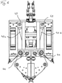
- An embodiment of a trench wall grab 10 according to the invention according to the Figures 1 to 4 has a framework-like, box-shaped guide frame 12 on which plate-shaped guide surfaces 14 are arranged on the side areas.
- the guide surfaces 14 serve to independently guide the trench wall grab 10 in the prepared slot with a rectangular cross section, the guide surfaces 14 coming to rest on the side walls of the prepared slot in a basically known manner.
- Laterally extendable control plates 16 can also be arranged on the guide frame 12 in order to influence a position of the trench wall grab 10 within the trench in a likewise known manner and to control the course of the trench to be created to a certain extent.
- a connecting device 18 is arranged at an upper end region of the guide frame 12, with which the diaphragm wall grab 10 is suspended, for example, on suspension cables 19 on a carrier device, not shown. Energy can also be supplied and controlled via the connecting device 18, with corresponding hydraulic lines, electrical lines and data lines not being shown in the figures.
- two spoon-like grab scoops 20 are arranged so that they can each pivot about an inner pivot bearing 22.
- removal teeth 24 are arranged interchangeably in a basically known manner.
- soil material is picked up over a rectangular cross-sectional area of the slot to form the slot.
- the pivot bearing 22 of the gripper scoops 20 are not attached directly to the guide frame 12, but rather to a bearing carriage 30 which is mounted on the guide frame 12 so that it can be displaced vertically along a linear guide 34.
- the box-shaped bearing carriage 30 has corresponding linear guide rails 32 for this purpose.
- the linear guide 34 and the guide rails 32 extend parallel to a vertical longitudinal axis of the guide frame 12.
- two hydraulic actuating cylinders 42a, 42b are provided in the illustrated trench wall grab 10 according to the invention, which are arranged in a V-arrangement on the trench wall grab 10 with respect to a central longitudinal plane of the guide frame 12, as illustrated in FIGS figures 2 and 4 is shown.
- the hydraulic actuating cylinders 42a, 42b are pivoted on the one hand with their cylinder housing on the upper region of the guide frame 12 on a first connecting bearing 43 and on the other hand with their piston rod on a second connecting bearing 44 on the bearing carriage 30, such as from 4 emerges.
- a twisting device can be arranged in the free space between the positioning cylinders 42a, 42b. With the twisting device, the grab scoops 20 can be twisted about the vertical axis by preferably 180°.
- the bearing carriage 30 with the gripper shovels 20 articulated thereon can be moved into a lower end position, which in the figures 1 and 2 is shown.
- the pivot bearings 22 of the grab shovels 20 are pressed downwards, with the grab shovels 20 being moved into an open position for picking up soil material.
- the pivot bearings 22 of the grab shovels 20 are moved upwards into an upper end position, which is in the Figures 3 and 4 is shown.
- a linkage lever 46 is arranged on the side of each of the gripper scoops 20 .
- the two linkage levers 46 are each pivotable via a first pivot bearing 47 with the guide frame 12 and on the other hand via a second pivot bearing 48 pivotable with the respective gripper bucket 20 connected.
- the linkage lever 46 causes the gripper shovels 20 to move from the open receiving position according to FIGS figures 1 and 2 simultaneously with the shifting of the pivot bearings 22 upwards into a closed position in which the grab buckets 20 are closed for picking up soil material, as illustrated in FIGS Figures 3 and 4 is shown.
- the hydraulic actuating cylinders 42a, 42b and the linkage levers 46 together with the displaceable bearing carriage 30 thus form an actuating device 40, by means of which the gripper shovels 20 can be actuated for opening and closing.
- the trench wall grab 10 in the closed position, in which it is usually pulled out of the trench, the trench wall grab 10 has a minimum vertical length or height, so that a particularly compact construction of the trench wall grab 10 is provided.
Claims (14)
- Benne de forage comportant :- un cadre de guidage (12) de type ossature,- un dispositif de liaison (18) sur une zone d'extrémité supérieure du cadre de guidage (12) pour suspendre la benne de forage (10), et- deux godets (20), lesquels sont disposés sur une zone d'extrémité inférieure du cadre de guidage (12) et peuvent être pivotés chacun autour d'un palier de pivotement de godet intérieur (22) entre une position de réception ouverte pour recevoir du matériau de sol et une position fermée, dans laquelle les godets (20) reposent l'un contre l'autre pour contenir le matériau de sol reçu, dans lequel les godets (20) sont reliés au cadre de guidage (12) respectivement par l'intermédiaire d'au moins un levier articulé extérieur (46),caractérisé en ce que
pour faire pivoter les godets (20), les paliers de pivotement de godet (22) intérieurs sont disposés sur au moins un chariot de montage (30), lequel est monté sur le cadre de guidage (12) de manière à pouvoir coulisser entre une position de chariot inférieure et une position de chariot supérieure. - Benne de forage selon la revendication 1,
caractérisé en ce que
un dispositif d'actionnement (40) est prévu pour faire pivoter les godets (20) entre la position de réception et la position fermée. - Benne de forage selon la revendication 2,
caractérisé en ce que
le dispositif d'actionnement (40) présente au moins un vérin de réglage (42a, 42b), en particulier un cylindre hydraulique. - Benne de forage selon la revendication 3,
caractérisé en ce que
l'au moins un vérin de réglage (42a, 42b) est disposé d'une part sur le cadre de guidage (12) et d'autre part sur le chariot de montage (30). - Benne de forage selon la revendication 3 ou 4,
caractérisé en ce
que sont prévus deux vérins de réglage (42a, 42b), lesquels sont disposés de manière symétrique par rapport à un axe longitudinal du cadre de guidage (12). - Benne de forage selon l'une des revendications 1 à 5,
caractérisé en ce queles godets (20) sont ouverts dans la position de réception quand le chariot de montage (30) est coulissé dans la position de chariot inférieure, eten ce que les godets (20) sont fermés dans la position fermée quand le chariot de montage (30) est coulissé dans la position de chariot supérieure. - Benne de forage selon l'une des revendications 1 à 6,
caractérisé en ce que
le chariot de montage (30) peut être coulissé sur le cadre de guidage (12) le long d'un guidage linéaire (34), lequel s'étend de manière parallèle par rapport à un axe longitudinal central du cadre de guidage (12). - Benne de forage selon l'une des revendications 1 à 7,
caractérisé en ce que
le levier articulé (46) est installé de manière articulée d'une part sur le cadre de guidage (12) et d'autre part sur le godet (20). - Benne de forage selon l'une quelconque des revendications 1 à 8,
caractérisé en ce que
les paliers de pivotement de godet (22) des godets (20) sont disposés sur un chariot de montage (30) commun à proximité d'un axe longitudinal central. - Benne de forage selon l'une des revendications 1 à 9,
caractérisé en ce que
une longueur verticale de la benne de forage (10) avec des godets (20) fermés dans la position fermée est inférieure à la longueur verticale du benne de forage (10) avec des godets (20) ouverts dans la position de réception ou au cours de l'opération de fermeture. - Engin de construction avec un appareil de support,
caractérisé en ce que
une benne de forage (10) selon l'une des revendications 1 à 10 est montée de manière ajustable verticalement sur l'appareil de support. - Procédé pour faire fonctionner une benne de forage (10) selon l'une des revendications 1 à 10, comportant :- un cadre de guidage (12) de type ossature,- un dispositif de liaison (18) sur une zone d'extrémité supérieure du cadre de guidage (12) pour suspendre la benne de forage (10), et- deux godets (20), lesquels sont disposés sur une zone d'extrémité inférieure du cadre de guidage (12) et peuvent pivoter chacun autour d'un palier de pivotement de godet (22) entre une position de réception ouverte pour recevoir du matériau de sol et une position fermée, dans laquelle les godets (20) reposent l'un contre l'autre pour contenir le matériau de sol reçu,dans lequel la benne de forage (10) avec des godets (20) ouverts est abaissée dans un sol, etles godets (20) sont fermés à réception du matériau de sol et la benne de forage (10) est relevée vers le haut,caractérisé en ce queune longueur verticale de la benne de forage (10) avec godets (20) fermés lors du relevage est inférieure ou égale à la longueur verticale du benne de forage (10) avec godets (20) ouverts lors de l'abaissement.
- Procédé de génie civil,
caractérisé en ce que
une tranchée est produite dans le sol au moyen d'un benne de forage (10) selon l'une des revendications 1 à 10. - Procédé de génie civil selon la revendication 13,
caractérisé en ce
que la tranchée est remplie d'une suspension durcissable pour former une paroi moulée.
Priority Applications (2)
| Application Number | Priority Date | Filing Date | Title |
|---|---|---|---|
| EP19199492.0A EP3798367B1 (fr) | 2019-09-25 | 2019-09-25 | Élément d'ancrage sur une tranchée, son procédé de fonctionnement et procédé de construction souterraine |
| CN202011024864.9A CN112554258B (zh) | 2019-09-25 | 2020-09-25 | 槽壁抓夹器、用于运行槽壁抓夹器的方法和地下工程方法 |
Applications Claiming Priority (1)
| Application Number | Priority Date | Filing Date | Title |
|---|---|---|---|
| EP19199492.0A EP3798367B1 (fr) | 2019-09-25 | 2019-09-25 | Élément d'ancrage sur une tranchée, son procédé de fonctionnement et procédé de construction souterraine |
Publications (2)
| Publication Number | Publication Date |
|---|---|
| EP3798367A1 EP3798367A1 (fr) | 2021-03-31 |
| EP3798367B1 true EP3798367B1 (fr) | 2022-03-09 |
Family
ID=68069508
Family Applications (1)
| Application Number | Title | Priority Date | Filing Date |
|---|---|---|---|
| EP19199492.0A Active EP3798367B1 (fr) | 2019-09-25 | 2019-09-25 | Élément d'ancrage sur une tranchée, son procédé de fonctionnement et procédé de construction souterraine |
Country Status (2)
| Country | Link |
|---|---|
| EP (1) | EP3798367B1 (fr) |
| CN (1) | CN112554258B (fr) |
Families Citing this family (3)
| Publication number | Priority date | Publication date | Assignee | Title |
|---|---|---|---|---|
| EP4249687A3 (fr) | 2021-08-12 | 2023-11-29 | BAUER Maschinen GmbH | Dispositif de préhension et procédé de fonctionnement d'un dispositif de préhension |
| EP4134489A1 (fr) | 2021-08-12 | 2023-02-15 | BAUER Maschinen GmbH | Dispositif préhenseur et procédé de fonctionnement d'un dispositif préhenseur |
| EP4296431A1 (fr) * | 2022-06-24 | 2023-12-27 | BAUER Spezialtiefbau GmbH | Procédé de pose et de construction d'une paroi d'appui dans le sol et paroi d'appui |
Family Cites Families (13)
| Publication number | Priority date | Publication date | Assignee | Title |
|---|---|---|---|---|
| GB799519A (en) * | 1956-03-07 | 1958-08-13 | Priestman Brothers | Improvements relating to grabs |
| FR1291709A (fr) * | 1961-03-16 | 1962-04-27 | Benoto Sa | Benne électrique à commande hydraulique |
| FR2040945A5 (fr) * | 1969-04-28 | 1971-01-22 | Allard Pierre | |
| US3684040A (en) * | 1970-06-24 | 1972-08-15 | P & Z Co Inc | Apparatus for actuating clam shell bucket |
| US3691356A (en) | 1970-12-10 | 1972-09-12 | Sperry Rand Corp | Speed command and throttle control system for aircraft |
| ZA836216B (en) * | 1982-09-13 | 1984-04-25 | Frankignoul Pieux Armes | Device for the suspension of a grab or grab bucket and grab or grab bucket apparatus incorporating said device |
| DE3805868A1 (de) * | 1988-02-25 | 1989-09-07 | Hochtief Ag Hoch Tiefbauten | Seilgefuehrter schlitzwandgreifer |
| DE3810459A1 (de) * | 1988-03-26 | 1989-10-12 | Hochtief Ag Hoch Tiefbauten | Seilgefuehrter schlitzwandgreifer |
| ES2328521T3 (es) | 2007-01-26 | 2009-11-13 | Bauer Maschinen Gmbh | Dispositivo de excavacion del suelo. |
| CN101736764B (zh) * | 2008-11-25 | 2012-05-23 | 上海金泰工程机械有限公司 | 一种冲击式挖掘装置 |
| ITMI20131529A1 (it) * | 2013-09-17 | 2015-03-18 | Soilmec Spa | Dispositivo per lo scavo di diaframmi |
| CN105951910A (zh) * | 2016-05-09 | 2016-09-21 | 同济大学 | 带有回转系统的双瓣液压抓斗 |
| EP3401444B1 (fr) * | 2017-05-11 | 2019-11-27 | BAUER Maschinen GmbH | Dispositif d'excavation de tranchée et procédé de fabrication de tranchées dans le sol |
-
2019
- 2019-09-25 EP EP19199492.0A patent/EP3798367B1/fr active Active
-
2020
- 2020-09-25 CN CN202011024864.9A patent/CN112554258B/zh active Active
Also Published As
| Publication number | Publication date |
|---|---|
| CN112554258B (zh) | 2022-11-29 |
| CN112554258A (zh) | 2021-03-26 |
| EP3798367A1 (fr) | 2021-03-31 |
Similar Documents
| Publication | Publication Date | Title |
|---|---|---|
| EP3798367B1 (fr) | Élément d'ancrage sur une tranchée, son procédé de fonctionnement et procédé de construction souterraine | |
| EP1068402B1 (fr) | Appareillage pour l'introduction d'un matériau étranger dans le sol et/ou pour le compactage du sol et méthode de production d'une colonne de matériau dans le sol | |
| DE2823822A1 (de) | Bagger | |
| DE3615068C1 (en) | Rope-guided trench-wall grab | |
| DE1634885C3 (de) | Klemmvorrichtung für einen auf einer waagerechten Trägerschiene verschiebbaren Ausleger eines Baggers | |
| WO2000031351A1 (fr) | Chargeuse pelleteuse mobile | |
| EP0412477B1 (fr) | Benne de forage comprenant des éléments d'encrage sur la paroi d'une tranchée | |
| DE19512070C2 (de) | Bohrgerät | |
| DE1634943A1 (de) | Hydraulischer Universalbagger | |
| EP3725950B1 (fr) | Benne de forage et procédé de fabrication d'une parois dans le sol | |
| DE2405142B1 (de) | Bohrgreifer fuer Pfahlgruendungen und Brunnenbohrungen | |
| EP0061047A1 (fr) | Procédé et dispositif pour l'emmagasinage de produits agricoles, tels que fourrage grossier et produits ensilés, jusque sous la charpente d'un bâtiment agricole | |
| EP2698474B1 (fr) | Dispositif de pose de pavés avec un dispositif de support de mâchoires de préhension | |
| EP2889431B1 (fr) | Machine de travail pour le fonctionnement de benne racleuse | |
| EP2789749A2 (fr) | Dispositif destiné à l'augmentation du rayon d'action d'une machine d'excavation et son utilisation | |
| DE2929463C2 (de) | Hydraulisch betätigter Bagger | |
| DE2707495A1 (de) | Transport- und verlegegeraet fuer im wesentlichen plattenfoermige strassenbelaege | |
| WO2012045444A1 (fr) | Machine de travail à fonction de burinage | |
| EP3725951B1 (fr) | Dispositif de benne et procédé de fabrication d'une fouille de fondation | |
| DE2750371A1 (de) | Arbeitsmaschine mit zwei arbeitsgeraeten | |
| DE2539761A1 (de) | Vorrichtung zum abbrechen einer schicht aus festem material, wie beton oder mauerwerk | |
| EP2801668A1 (fr) | Dispositif de creusement pour la réalisation d'une fente dans le sol | |
| DE3102166C2 (de) | Vorrichtung zum Erzielen einer an die Dachneigung eines Gebäudes angepaßten Bahnkurve eines an einem Tragrahmen gelagerten Wippauslegers | |
| DE19511798A1 (de) | Abstützung für eine mobile Seilwinde | |
| DE102022125077A1 (de) | Arbeitsgerät für einen Bagger |
Legal Events
| Date | Code | Title | Description |
|---|---|---|---|
| PUAI | Public reference made under article 153(3) epc to a published international application that has entered the european phase |
Free format text: ORIGINAL CODE: 0009012 |
|
| STAA | Information on the status of an ep patent application or granted ep patent |
Free format text: STATUS: REQUEST FOR EXAMINATION WAS MADE |
|
| 17P | Request for examination filed |
Effective date: 20200311 |
|
| AK | Designated contracting states |
Kind code of ref document: A1 Designated state(s): AL AT BE BG CH CY CZ DE DK EE ES FI FR GB GR HR HU IE IS IT LI LT LU LV MC MK MT NL NO PL PT RO RS SE SI SK SM TR |
|
| AX | Request for extension of the european patent |
Extension state: BA ME |
|
| GRAP | Despatch of communication of intention to grant a patent |
Free format text: ORIGINAL CODE: EPIDOSNIGR1 |
|
| STAA | Information on the status of an ep patent application or granted ep patent |
Free format text: STATUS: GRANT OF PATENT IS INTENDED |
|
| INTG | Intention to grant announced |
Effective date: 20211022 |
|
| GRAS | Grant fee paid |
Free format text: ORIGINAL CODE: EPIDOSNIGR3 |
|
| GRAA | (expected) grant |
Free format text: ORIGINAL CODE: 0009210 |
|
| STAA | Information on the status of an ep patent application or granted ep patent |
Free format text: STATUS: THE PATENT HAS BEEN GRANTED |
|
| AK | Designated contracting states |
Kind code of ref document: B1 Designated state(s): AL AT BE BG CH CY CZ DE DK EE ES FI FR GB GR HR HU IE IS IT LI LT LU LV MC MK MT NL NO PL PT RO RS SE SI SK SM TR |
|
| REG | Reference to a national code |
Ref country code: CH Ref legal event code: EP Ref country code: AT Ref legal event code: REF Ref document number: 1474266 Country of ref document: AT Kind code of ref document: T Effective date: 20220315 |
|
| REG | Reference to a national code |
Ref country code: DE Ref legal event code: R096 Ref document number: 502019003636 Country of ref document: DE |
|
| REG | Reference to a national code |
Ref country code: IE Ref legal event code: FG4D Free format text: LANGUAGE OF EP DOCUMENT: GERMAN |
|
| REG | Reference to a national code |
Ref country code: LT Ref legal event code: MG9D |
|
| REG | Reference to a national code |
Ref country code: NL Ref legal event code: MP Effective date: 20220309 |
|
| PG25 | Lapsed in a contracting state [announced via postgrant information from national office to epo] |
Ref country code: SE Free format text: LAPSE BECAUSE OF FAILURE TO SUBMIT A TRANSLATION OF THE DESCRIPTION OR TO PAY THE FEE WITHIN THE PRESCRIBED TIME-LIMIT Effective date: 20220309 Ref country code: RS Free format text: LAPSE BECAUSE OF FAILURE TO SUBMIT A TRANSLATION OF THE DESCRIPTION OR TO PAY THE FEE WITHIN THE PRESCRIBED TIME-LIMIT Effective date: 20220309 Ref country code: NO Free format text: LAPSE BECAUSE OF FAILURE TO SUBMIT A TRANSLATION OF THE DESCRIPTION OR TO PAY THE FEE WITHIN THE PRESCRIBED TIME-LIMIT Effective date: 20220609 Ref country code: LT Free format text: LAPSE BECAUSE OF FAILURE TO SUBMIT A TRANSLATION OF THE DESCRIPTION OR TO PAY THE FEE WITHIN THE PRESCRIBED TIME-LIMIT Effective date: 20220309 Ref country code: HR Free format text: LAPSE BECAUSE OF FAILURE TO SUBMIT A TRANSLATION OF THE DESCRIPTION OR TO PAY THE FEE WITHIN THE PRESCRIBED TIME-LIMIT Effective date: 20220309 Ref country code: BG Free format text: LAPSE BECAUSE OF FAILURE TO SUBMIT A TRANSLATION OF THE DESCRIPTION OR TO PAY THE FEE WITHIN THE PRESCRIBED TIME-LIMIT Effective date: 20220609 |
|
| PG25 | Lapsed in a contracting state [announced via postgrant information from national office to epo] |
Ref country code: LV Free format text: LAPSE BECAUSE OF FAILURE TO SUBMIT A TRANSLATION OF THE DESCRIPTION OR TO PAY THE FEE WITHIN THE PRESCRIBED TIME-LIMIT Effective date: 20220309 Ref country code: GR Free format text: LAPSE BECAUSE OF FAILURE TO SUBMIT A TRANSLATION OF THE DESCRIPTION OR TO PAY THE FEE WITHIN THE PRESCRIBED TIME-LIMIT Effective date: 20220610 Ref country code: FI Free format text: LAPSE BECAUSE OF FAILURE TO SUBMIT A TRANSLATION OF THE DESCRIPTION OR TO PAY THE FEE WITHIN THE PRESCRIBED TIME-LIMIT Effective date: 20220309 |
|
| PG25 | Lapsed in a contracting state [announced via postgrant information from national office to epo] |
Ref country code: NL Free format text: LAPSE BECAUSE OF FAILURE TO SUBMIT A TRANSLATION OF THE DESCRIPTION OR TO PAY THE FEE WITHIN THE PRESCRIBED TIME-LIMIT Effective date: 20220309 |
|
| PG25 | Lapsed in a contracting state [announced via postgrant information from national office to epo] |
Ref country code: SM Free format text: LAPSE BECAUSE OF FAILURE TO SUBMIT A TRANSLATION OF THE DESCRIPTION OR TO PAY THE FEE WITHIN THE PRESCRIBED TIME-LIMIT Effective date: 20220309 Ref country code: SK Free format text: LAPSE BECAUSE OF FAILURE TO SUBMIT A TRANSLATION OF THE DESCRIPTION OR TO PAY THE FEE WITHIN THE PRESCRIBED TIME-LIMIT Effective date: 20220309 Ref country code: RO Free format text: LAPSE BECAUSE OF FAILURE TO SUBMIT A TRANSLATION OF THE DESCRIPTION OR TO PAY THE FEE WITHIN THE PRESCRIBED TIME-LIMIT Effective date: 20220309 Ref country code: PT Free format text: LAPSE BECAUSE OF FAILURE TO SUBMIT A TRANSLATION OF THE DESCRIPTION OR TO PAY THE FEE WITHIN THE PRESCRIBED TIME-LIMIT Effective date: 20220711 Ref country code: ES Free format text: LAPSE BECAUSE OF FAILURE TO SUBMIT A TRANSLATION OF THE DESCRIPTION OR TO PAY THE FEE WITHIN THE PRESCRIBED TIME-LIMIT Effective date: 20220309 Ref country code: EE Free format text: LAPSE BECAUSE OF FAILURE TO SUBMIT A TRANSLATION OF THE DESCRIPTION OR TO PAY THE FEE WITHIN THE PRESCRIBED TIME-LIMIT Effective date: 20220309 Ref country code: CZ Free format text: LAPSE BECAUSE OF FAILURE TO SUBMIT A TRANSLATION OF THE DESCRIPTION OR TO PAY THE FEE WITHIN THE PRESCRIBED TIME-LIMIT Effective date: 20220309 |
|
| PG25 | Lapsed in a contracting state [announced via postgrant information from national office to epo] |
Ref country code: PL Free format text: LAPSE BECAUSE OF FAILURE TO SUBMIT A TRANSLATION OF THE DESCRIPTION OR TO PAY THE FEE WITHIN THE PRESCRIBED TIME-LIMIT Effective date: 20220309 Ref country code: IS Free format text: LAPSE BECAUSE OF FAILURE TO SUBMIT A TRANSLATION OF THE DESCRIPTION OR TO PAY THE FEE WITHIN THE PRESCRIBED TIME-LIMIT Effective date: 20220709 Ref country code: AL Free format text: LAPSE BECAUSE OF FAILURE TO SUBMIT A TRANSLATION OF THE DESCRIPTION OR TO PAY THE FEE WITHIN THE PRESCRIBED TIME-LIMIT Effective date: 20220309 |
|
| REG | Reference to a national code |
Ref country code: DE Ref legal event code: R097 Ref document number: 502019003636 Country of ref document: DE |
|
| PLBE | No opposition filed within time limit |
Free format text: ORIGINAL CODE: 0009261 |
|
| STAA | Information on the status of an ep patent application or granted ep patent |
Free format text: STATUS: NO OPPOSITION FILED WITHIN TIME LIMIT |
|
| PG25 | Lapsed in a contracting state [announced via postgrant information from national office to epo] |
Ref country code: DK Free format text: LAPSE BECAUSE OF FAILURE TO SUBMIT A TRANSLATION OF THE DESCRIPTION OR TO PAY THE FEE WITHIN THE PRESCRIBED TIME-LIMIT Effective date: 20220309 |
|
| 26N | No opposition filed |
Effective date: 20221212 |
|
| PG25 | Lapsed in a contracting state [announced via postgrant information from national office to epo] |
Ref country code: SI Free format text: LAPSE BECAUSE OF FAILURE TO SUBMIT A TRANSLATION OF THE DESCRIPTION OR TO PAY THE FEE WITHIN THE PRESCRIBED TIME-LIMIT Effective date: 20220309 |
|
| PG25 | Lapsed in a contracting state [announced via postgrant information from national office to epo] |
Ref country code: MC Free format text: LAPSE BECAUSE OF FAILURE TO SUBMIT A TRANSLATION OF THE DESCRIPTION OR TO PAY THE FEE WITHIN THE PRESCRIBED TIME-LIMIT Effective date: 20220309 |
|
| REG | Reference to a national code |
Ref country code: CH Ref legal event code: PL |
|
| REG | Reference to a national code |
Ref country code: BE Ref legal event code: MM Effective date: 20220930 |
|
| P01 | Opt-out of the competence of the unified patent court (upc) registered |
Effective date: 20230524 |
|
| PG25 | Lapsed in a contracting state [announced via postgrant information from national office to epo] |
Ref country code: LU Free format text: LAPSE BECAUSE OF NON-PAYMENT OF DUE FEES Effective date: 20220925 |
|
| PG25 | Lapsed in a contracting state [announced via postgrant information from national office to epo] |
Ref country code: LI Free format text: LAPSE BECAUSE OF NON-PAYMENT OF DUE FEES Effective date: 20220930 Ref country code: IE Free format text: LAPSE BECAUSE OF NON-PAYMENT OF DUE FEES Effective date: 20220925 Ref country code: CH Free format text: LAPSE BECAUSE OF NON-PAYMENT OF DUE FEES Effective date: 20220930 |
|
| PG25 | Lapsed in a contracting state [announced via postgrant information from national office to epo] |
Ref country code: BE Free format text: LAPSE BECAUSE OF NON-PAYMENT OF DUE FEES Effective date: 20220930 |
|
| PGFP | Annual fee paid to national office [announced via postgrant information from national office to epo] |
Ref country code: IT Payment date: 20230908 Year of fee payment: 5 |
|
| PGFP | Annual fee paid to national office [announced via postgrant information from national office to epo] |
Ref country code: FR Payment date: 20230907 Year of fee payment: 5 Ref country code: DE Payment date: 20230904 Year of fee payment: 5 |