EP3798367B1 - Slotted wall gripper, method for operating same, and civil engineering method - Google Patents
Slotted wall gripper, method for operating same, and civil engineering method Download PDFInfo
- Publication number
- EP3798367B1 EP3798367B1 EP19199492.0A EP19199492A EP3798367B1 EP 3798367 B1 EP3798367 B1 EP 3798367B1 EP 19199492 A EP19199492 A EP 19199492A EP 3798367 B1 EP3798367 B1 EP 3798367B1
- Authority
- EP
- European Patent Office
- Prior art keywords
- grab
- diaphragm wall
- shovels
- guide frame
- wall grab
- Prior art date
- Legal status (The legal status is an assumption and is not a legal conclusion. Google has not performed a legal analysis and makes no representation as to the accuracy of the status listed.)
- Active
Links
- 238000000034 method Methods 0.000 title claims description 10
- 238000012407 engineering method Methods 0.000 title claims description 8
- 239000000463 material Substances 0.000 claims description 17
- 238000010276 construction Methods 0.000 claims description 6
- 239000000725 suspension Substances 0.000 claims description 5
- 239000002689 soil Substances 0.000 description 14
- 230000004323 axial length Effects 0.000 description 4
- 230000018109 developmental process Effects 0.000 description 4
- 239000002002 slurry Substances 0.000 description 4
- 238000009412 basement excavation Methods 0.000 description 2
- 238000006073 displacement reaction Methods 0.000 description 2
- 229910000831 Steel Inorganic materials 0.000 description 1
- 230000001419 dependent effect Effects 0.000 description 1
- 239000010432 diamond Substances 0.000 description 1
- 230000001771 impaired effect Effects 0.000 description 1
- 229910052500 inorganic mineral Inorganic materials 0.000 description 1
- 238000009434 installation Methods 0.000 description 1
- 239000011707 mineral Substances 0.000 description 1
- 238000005065 mining Methods 0.000 description 1
- 230000035515 penetration Effects 0.000 description 1
- 239000002994 raw material Substances 0.000 description 1
- 230000002787 reinforcement Effects 0.000 description 1
- 239000010959 steel Substances 0.000 description 1
Images


Classifications
-
- E—FIXED CONSTRUCTIONS
- E02—HYDRAULIC ENGINEERING; FOUNDATIONS; SOIL SHIFTING
- E02D—FOUNDATIONS; EXCAVATIONS; EMBANKMENTS; UNDERGROUND OR UNDERWATER STRUCTURES
- E02D17/00—Excavations; Bordering of excavations; Making embankments
- E02D17/13—Foundation slots or slits; Implements for making these slots or slits
-
- E—FIXED CONSTRUCTIONS
- E02—HYDRAULIC ENGINEERING; FOUNDATIONS; SOIL SHIFTING
- E02F—DREDGING; SOIL-SHIFTING
- E02F5/00—Dredgers or soil-shifting machines for special purposes
- E02F5/02—Dredgers or soil-shifting machines for special purposes for digging trenches or ditches
- E02F5/025—Dredgers or soil-shifting machines for special purposes for digging trenches or ditches with scraper-buckets, dippers or shovels
-
- E—FIXED CONSTRUCTIONS
- E02—HYDRAULIC ENGINEERING; FOUNDATIONS; SOIL SHIFTING
- E02F—DREDGING; SOIL-SHIFTING
- E02F3/00—Dredgers; Soil-shifting machines
- E02F3/04—Dredgers; Soil-shifting machines mechanically-driven
- E02F3/46—Dredgers; Soil-shifting machines mechanically-driven with reciprocating digging or scraping elements moved by cables or hoisting ropes ; Drives or control devices therefor
- E02F3/47—Dredgers; Soil-shifting machines mechanically-driven with reciprocating digging or scraping elements moved by cables or hoisting ropes ; Drives or control devices therefor with grab buckets
- E02F3/475—Dredgers; Soil-shifting machines mechanically-driven with reciprocating digging or scraping elements moved by cables or hoisting ropes ; Drives or control devices therefor with grab buckets for making foundation slots
-
- E—FIXED CONSTRUCTIONS
- E02—HYDRAULIC ENGINEERING; FOUNDATIONS; SOIL SHIFTING
- E02F—DREDGING; SOIL-SHIFTING
- E02F3/00—Dredgers; Soil-shifting machines
- E02F3/04—Dredgers; Soil-shifting machines mechanically-driven
- E02F3/46—Dredgers; Soil-shifting machines mechanically-driven with reciprocating digging or scraping elements moved by cables or hoisting ropes ; Drives or control devices therefor
- E02F3/58—Component parts
- E02F3/60—Buckets, scrapers, or other digging elements
Definitions
- the invention relates to a trench wall grab with a skeleton-like guide frame, a connecting device on an upper end area of the guide frame for suspending the trench wall grab and two grab buckets, which are arranged on a lower end area of the guide frame and each move around an inner bucket pivot bearing between an open pick-up position for picking up soil material and can be pivoted to a closed position in which the gripper shovels abut one another to grip the picked-up soil material, according to the preamble of claim 1.
- the invention also relates to a method for operating a trench wall grab with a framework-like guide frame, a connecting device for suspending the trench wall grab on an upper end area of the guide frame and two grab buckets, which are arranged on a lower end area of the guide frame and each move around a bucket pivot bearing between an open receiving position for picking up soil material and a closed position in which the grab buckets abut one another for embracing the picked up soil material, wherein the diaphragm wall grab is lowered into a soil with the grab buckets open, and the grab buckets are closed while picking up soil material and the diaphragm wall grab is raised upwards , according to the preamble of claim 12.
- the invention also relates to a civil engineering method according to claim 13.
- a generic diaphragm wall grab is, for example, from EP 1 950 353 A1 out.
- the grab scoops are pivotably mounted on a lower bearing area of the guide frame.
- diagonally extending linkage levers are provided, which are articulated on the one hand on the gripper scoops and on the other hand on an actuating carriage.
- the actuating carriage is mounted on the guide frame in a vertically displaceable manner and can be displaced between a lower position and an upper position by means of a hydraulic cylinder. In the lower position of the actuating carriage, the gripper scoops are pivoted downwards about the pivot bearing and closed, while in the upper position of the actuating carriage the gripper scoops are pulled up and pivoted open about the pivot bearing.
- an axial length of the diaphragm wall grab when the grab scoops are closed is greater than an axial length of the diaphragm wall grab when the scoops are open.
- the cross-section of the guide frame is adapted to the cross-section of the trench, so that the trench wall grab can guide itself through the guide frame with its contact surfaces in the trench.
- the guide frame In order to ensure the best possible guidance of the slurry wall grab in the prepared slot, the guide frame must have a certain height, which can be up to 10 m and more. This can limit the use of a diaphragm wall grab, since there must be enough free space above the ground.
- the free space above ground can be limited so that only diaphragm wall grabs with a correspondingly short vertical length can be used.
- it is known to reduce the skeleton-like guide frame accordingly in order to reduce the axial length of a trench wall grab.
- this is only possible to a certain extent, since otherwise an adequate guiding function of the box-like guiding frame is impaired.
- the DE 38 05 868 A1 teaches a trench wall grab with a cable suspended guide frame for guiding in the trench.
- a grab shovel carrier can be moved and is mounted in a height-adjustable manner using hydraulic cylinders.
- the grab shovels are mounted on the grab shovel carrier and can be actuated by means of actuating cylinders which are articulated on the one hand on the grab shovels and on the other hand on the grab shovel carrier.
- the UK799,519 relates to a non-generic gripper arrangement which is not suitable for guided use in a slot.
- a diaphragm wall grab which has a reduced working height.
- an outer part of the framework-like guide frame is designed to be foldable, with the guide frame being able to be folded away to the side when the diaphragm wall grab is lifted out of the slot to reduce the structural height.
- the actuation of the gripper scoops which are linked to a fixed position of the guide frame with their inner pivot points, ie the pivot points assigned to the closing edge, also takes place via link rods attached laterally, ie further outside, to the gripper scoops. These are connected to an actuating carriage that is moved by an actuating cable. The grab shovels are pushed down to close and pulled up to open.
- a folding mechanism for the guide frame is fundamentally complex and also impairs the stability of the framework-like guide frame, which should have the highest possible rigidity.
- the invention is based on the object of specifying a trench wall grab, a method for operating such a trench wall grab and a civil engineering method which enable reliable operation of a trench wall grab even at a limited working height.
- the object is achieved by a trench wall grab having the features of claim 1, a method for operating the trench wall grab according to claim 12 and a civil engineering method according to claim 13.
- Preferred embodiments of the invention are specified in the respective dependent claims.
- the diaphragm wall grab according to the invention is characterized in that, for pivoting the grab shovels, the inner shovel swivel bearings are arranged on at least one bearing carriage, which is mounted displaceably relative to the guide frame between a lower carriage position and an upper carriage position, and that the grab shovels each have at least one outer linkage lever with the Guide frames are connected.
- a basic idea of the invention is to bring about the displacement movement for opening and closing the grab shovels by vertically adjusting the inner pivot bearing of the grab shovels.
- the inner pivot bearings are arranged on at least one bearing carriage, which is slidably mounted between an upper carriage position and a lower carriage position. This considerably simplifies the mechanics of the gripper, since only one adjustment movement has to be generated for the at least one carriage.
- the guide frame can also be designed as a largely rigid frame in the form of a box, with contact or guide surfaces in particular being provided for contact with the walls of the slot.
- the gripper shovels When the gripper shovels are actuated by moving the bearing carriage itself, it is expedient according to the invention for the gripper shovels to be connected to the guide frame via at least one linkage lever.
- the linkage levers When the gripper scoops are displaced by the bearing carriage, on which the gripper scoops are pivotally articulated, the linkage levers cause the gripper scoops to be pivoted about their pivot bearings into the desired closed position or the receiving position.
- the bearing carriage with the gripper scoops is pushed up, a closing movement can be effected and when it is pushed down, an opening movement of the gripper scoops can be effected.
- the outer pivot point does not move on a circular path, but on a superimposition of a circular path and vertical movement of the center of the circle ("inner pivot bearing").
- the lowest point of the grab shovel moves upwards during closing, which means that the shovel height when closed is smaller than when it is open or during the closing process.
- a preferred embodiment of the invention consists in that an actuating device is provided for pivoting the gripper shovels between the pick-up position and the closed position.
- the actuator can be any Be linear drive or a suitable rotary drive, which causes a pivoting of the grab shovels directly or via an actuating mechanism.
- the actuating device can have a traction or actuating cable with which the gripper shovels can be pivoted.
- the actuating device has at least one actuating cylinder, in particular a hydraulic cylinder.
- a hydraulic cylinder With a hydraulic cylinder, high actuating forces can be applied in a limited installation space.
- a separate actuating cylinder can preferably be provided for each grab shovel, which swivels it.
- a particularly efficient construction of the trench wall grab is achieved in that the at least one actuating cylinder is arranged on the one hand on the grab frame and on the other hand on the bearing carriage. If an actuating cylinder, in particular a hydraulic cylinder, is arranged on the bearing carriage, this can serve as an actuating carriage for pivoting the gripper shovels. With the at least one actuating cylinder, both a change in the vertical length of the trench wall grab and a pivoting movement of the grab scoops can be effected by moving the bearing carriage.
- two adjusting cylinders are provided, which are arranged symmetrically to one another with respect to a longitudinal axis of the gripper frame.
- the actuating cylinders can be arranged at an angle to a vertical center plane of the diaphragm wall grab and in particular act directly on the guide frame on the one hand and on the bearing carriage or on the grab shovels on the other.
- Efficient operation of the diaphragm wall grab can be achieved according to one embodiment of the invention in that the grab shovels are open in the pick-up position when the storage carriage is moved to the lower carriage position, and that the grab shovels are closed in the closed position when the storage carriage is in the upper carriage position is shifted.
- the trench wall grab has a closed grab bucket less vertical length than when the grab buckets are open.
- a reduction in the vertical length can result when the gripper scoops are closed by pivoting the gripper scoops downwards due to the arrangement of the pivot bearing and articulation bearing.
- the diaphragm wall grab can have the smallest possible vertical length or height, especially when exiting a trench above the ground, so that the diaphragm wall grab can also be used in cramped conditions with a limited working height.
- the bearing carriage on which the gripper shovels are articulated, can be mounted in any desired manner.
- the bearing carriage can be displaced on the guide frame along a linear guide, which runs parallel to a central longitudinal axis of the guide frame.
- the at least one actuating cylinder can be arranged centrally and parallel to the central longitudinal axis, so that actuation of the bearing carriage with as little lateral force as possible is ensured.
- the linkage lever In order to avoid jamming, it is expedient here for the linkage lever to be articulated on the one hand on the guide frame and on the other hand on the grab shovel.
- the linkage lever itself can perform a certain pivoting movement in relation to the guide frame and also the gripper shovels.
- the articulated storage can be done via bushings or roller bearings.
- the two gripper scoops are each mounted on bearing carriages that can be displaced separately from one another, as a result of which an asymmetrical gripper scoop movement could be produced.
- a particularly efficient construction of the diaphragm wall grab results from the fact that the bucket swivel bearings of the grab buckets are arranged close to a central longitudinal axis on a common bearing carriage.
- the bearing carriage and the entire arrangement of the grab shovels are symmetrical to a central longitudinal plane of the trench wall grab, which usually extends vertically.
- the aim of the invention is in particular that the vertical length of the trench wall grab with closed grab buckets in the closed position is smaller than the vertical length of the diaphragm wall grab with the grab buckets open in the pick-up position.
- the invention also includes a construction machine with a carrier device, the diaphragm wall grab described above according to the invention being vertically adjustable on the carrier device.
- the carrier device can be a stationary guide or a movable carrier device, which has a caterpillar chassis, for example.
- the diaphragm wall grab can be mounted in a vertically adjustable manner, for example on a crane boom or mast, in particular by means of a guide rope or a guide rod.
- the method for operating a diaphragm wall grab is characterized in that the vertical length of the diaphragm wall grab with closed grab buckets when lifting is smaller than the vertical length of the diaphragm wall grab with open grab buckets when lowering.
- the vertical length of the trench wall grab can be reduced outside of a trench when the grab buckets are closed. This is particularly important when the grab bucket with picked up soil material is pulled out of the slot and moved to an unloading position.
- the grab scoops can be closed again after unloading and moved back into the slot in the closed and thus vertically compact form.
- a preferred operating sequence for actuating the diaphragm wall grab and digging out soil material has the following steps in particular: A closed gripper is positioned over the slot to be made. A first guide trench for receiving at least the lower portion of the diaphragm wall grab can be previously dug into the ground at the position.
- the grab shovels can then be opened to pick up the soil material, with the diaphragm wall grab being able to assume a greater vertical length.
- the diaphragm wall grab can be lowered with the grab buckets open until it comes into contact with the ground.
- the grab shovels of the diaphragm wall grab are then closed by pulling the grab shovels upwards.
- the slurry wall grab can be lowered further. Closing the grab buckets while the grab buckets are filling with soil allows the diaphragm wall grab to resume its shorter vertical length.
- the diaphragm wall grab is then lifted with the grab buckets closed and moved to an unloading point.
- the diaphragm wall grab is unloaded by opening the grab buckets.
- the grab shovels can then be closed again and swiveled back to the working position in order to carry out another excavation process.
- the invention further relates to a civil engineering method in which a trench is created in the ground by means of the trench wall grab according to the invention described above.
- a large number of slits can be created next to one another, so that overall a slit that is longer in the horizontal direction is created. Material is excavated as previously described.
- the slot is filled with a hardenable suspension to form a slot wall.
- a concrete mass can be introduced into the slot.
- reinforcement elements such as metallic lattice cages or steel girders, can be let into the slot.
- the diaphragm wall can be designed as an enclosing wall for large construction pits, a cut-off wall or as a retaining wall.
- a civil engineering method within the meaning of the invention also includes mining of mineral resources by means of the diaphragm wall grab.
- Raw materials contained in the soil, such as e.g. B. ores or diamonds are filtered out of the excavation and the slot is filled with the overburden.
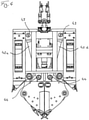
- An embodiment of a trench wall grab 10 according to the invention according to the Figures 1 to 4 has a framework-like, box-shaped guide frame 12 on which plate-shaped guide surfaces 14 are arranged on the side areas.
- the guide surfaces 14 serve to independently guide the trench wall grab 10 in the prepared slot with a rectangular cross section, the guide surfaces 14 coming to rest on the side walls of the prepared slot in a basically known manner.
- Laterally extendable control plates 16 can also be arranged on the guide frame 12 in order to influence a position of the trench wall grab 10 within the trench in a likewise known manner and to control the course of the trench to be created to a certain extent.
- a connecting device 18 is arranged at an upper end region of the guide frame 12, with which the diaphragm wall grab 10 is suspended, for example, on suspension cables 19 on a carrier device, not shown. Energy can also be supplied and controlled via the connecting device 18, with corresponding hydraulic lines, electrical lines and data lines not being shown in the figures.
- two spoon-like grab scoops 20 are arranged so that they can each pivot about an inner pivot bearing 22.
- removal teeth 24 are arranged interchangeably in a basically known manner.
- soil material is picked up over a rectangular cross-sectional area of the slot to form the slot.
- the pivot bearing 22 of the gripper scoops 20 are not attached directly to the guide frame 12, but rather to a bearing carriage 30 which is mounted on the guide frame 12 so that it can be displaced vertically along a linear guide 34.
- the box-shaped bearing carriage 30 has corresponding linear guide rails 32 for this purpose.
- the linear guide 34 and the guide rails 32 extend parallel to a vertical longitudinal axis of the guide frame 12.
- two hydraulic actuating cylinders 42a, 42b are provided in the illustrated trench wall grab 10 according to the invention, which are arranged in a V-arrangement on the trench wall grab 10 with respect to a central longitudinal plane of the guide frame 12, as illustrated in FIGS figures 2 and 4 is shown.
- the hydraulic actuating cylinders 42a, 42b are pivoted on the one hand with their cylinder housing on the upper region of the guide frame 12 on a first connecting bearing 43 and on the other hand with their piston rod on a second connecting bearing 44 on the bearing carriage 30, such as from 4 emerges.
- a twisting device can be arranged in the free space between the positioning cylinders 42a, 42b. With the twisting device, the grab scoops 20 can be twisted about the vertical axis by preferably 180°.
- the bearing carriage 30 with the gripper shovels 20 articulated thereon can be moved into a lower end position, which in the figures 1 and 2 is shown.
- the pivot bearings 22 of the grab shovels 20 are pressed downwards, with the grab shovels 20 being moved into an open position for picking up soil material.
- the pivot bearings 22 of the grab shovels 20 are moved upwards into an upper end position, which is in the Figures 3 and 4 is shown.
- a linkage lever 46 is arranged on the side of each of the gripper scoops 20 .
- the two linkage levers 46 are each pivotable via a first pivot bearing 47 with the guide frame 12 and on the other hand via a second pivot bearing 48 pivotable with the respective gripper bucket 20 connected.
- the linkage lever 46 causes the gripper shovels 20 to move from the open receiving position according to FIGS figures 1 and 2 simultaneously with the shifting of the pivot bearings 22 upwards into a closed position in which the grab buckets 20 are closed for picking up soil material, as illustrated in FIGS Figures 3 and 4 is shown.
- the hydraulic actuating cylinders 42a, 42b and the linkage levers 46 together with the displaceable bearing carriage 30 thus form an actuating device 40, by means of which the gripper shovels 20 can be actuated for opening and closing.
- the trench wall grab 10 in the closed position, in which it is usually pulled out of the trench, the trench wall grab 10 has a minimum vertical length or height, so that a particularly compact construction of the trench wall grab 10 is provided.
Description
Die Erfindung betrifft einen Schlitzwandgreifer mit einem gerüstartigen Führungsrahmen, einer Verbindungseinrichtung an einem oberen Endbereich des Führungsrahmens zum Aufhängen des Schlitzwandgreifers und zwei Greiferschaufeln, welche an einem unteren Endbereich des Führungsrahmens angeordnet sind und jeweils um ein inneres Schaufelschwenklager zwischen einer geöffneten Aufnahmeposition zum Aufnehmen von Bodenmaterial und einer Schließposition schwenkbar sind, in welcher die Greiferschaufeln zum Umfassen des aufgenommenen Bodenmaterials aneinander anliegen, gemäß dem Oberbegriff des Anspruches 1.The invention relates to a trench wall grab with a skeleton-like guide frame, a connecting device on an upper end area of the guide frame for suspending the trench wall grab and two grab buckets, which are arranged on a lower end area of the guide frame and each move around an inner bucket pivot bearing between an open pick-up position for picking up soil material and can be pivoted to a closed position in which the gripper shovels abut one another to grip the picked-up soil material, according to the preamble of claim 1.
Des Weiteren betrifft die Erfindung ein Verfahren zum Betrieb eines Schlitzwandgreifers mit einem gerüstartigen Führungsrahmen, einer Verbindungseinrichtung zum Aufhängen des Schlitzwandgreifers an einem oberen Endbereich des Führungsrahmens und zwei Greiferschaufeln, welche an einem unteren Endbereich des Führungsrahmens angeordnet sind und jeweils um ein Schaufelschwenklager zwischen einer geöffneten Aufnahmeposition zum Aufnehmen von Bodenmaterial und einer Schließposition schwenkbar sind, in welcher die Greiferschaufeln zum Umfassen des aufgenommenen Bodenmaterials aneinander anliegen, wobei der Schlitzwandgreifer mit geöffneten Greiferschaufeln in einen Boden abgesenkt wird, und die Greiferschaufeln unter Aufnahme von Bodenmaterial geschlossen werden und der Schlitzwandgreifer nach oben angehoben wird, gemäß dem Oberbegriff des Anspruches 12.The invention also relates to a method for operating a trench wall grab with a framework-like guide frame, a connecting device for suspending the trench wall grab on an upper end area of the guide frame and two grab buckets, which are arranged on a lower end area of the guide frame and each move around a bucket pivot bearing between an open receiving position for picking up soil material and a closed position in which the grab buckets abut one another for embracing the picked up soil material, wherein the diaphragm wall grab is lowered into a soil with the grab buckets open, and the grab buckets are closed while picking up soil material and the diaphragm wall grab is raised upwards , according to the preamble of
Schließlich betrifft die Erfindung noch ein Tiefbauverfahren nach Anspruch 13.Finally, the invention also relates to a civil engineering method according to claim 13.
Ein gattungsgemäßer Schlitzwandgreifer geht beispielsweise aus der
Bei diesem bekannten Schlitzwandgreifer ist somit eine axiale Länge des Schlitzwandgreifers bei geschlossenen Greiferschaufeln größer als eine axiale Länge des Schlitzwandgreifers bei geöffneten Greiferschaufeln.In this known diaphragm wall grab, an axial length of the diaphragm wall grab when the grab scoops are closed is greater than an axial length of the diaphragm wall grab when the scoops are open.
Der Führungsrahmen ist mit seinem Querschnitt an den Querschnitt des Schlitzes angepasst, so dass der Schlitzwandgreifer sich durch den Führungsrahmen mit seinen Anlageflächen selbst im Schlitz führen kann.The cross-section of the guide frame is adapted to the cross-section of the trench, so that the trench wall grab can guide itself through the guide frame with its contact surfaces in the trench.
Um eine möglichst gute Führung des Schlitzwandgreifers in dem erstellten Schlitz zu gewährleisten, muss der Führungsrahmen eine gewisse Höhe aufweisen, die bis zu 10 m und mehr betragen kann. Hierdurch kann der Einsatz eines Schlitzwandgreifers beschränkt werden, da genügend Freiraum über dem Boden gegeben sein muss.In order to ensure the best possible guidance of the slurry wall grab in the prepared slot, the guide frame must have a certain height, which can be up to 10 m and more. This can limit the use of a diaphragm wall grab, since there must be enough free space above the ground.
An bestimmten Einsatzorten, etwa unter Durchführungen oder in Gebäuden kann der Freiraum über einem Boden begrenzt sein, so dass nur Schlitzwandgreifer mit entsprechend geringer vertikaler Länge eingesetzt werden können. Grundsätzlich ist es dabei bekannt, zur Verringerung der axialen Länge eines Schlitzwandgreifers den gerüstartigen Führungsrahmen entsprechend zu reduzieren. Dies ist jedoch nur bis zu einem gewissen Maß möglich, da ansonsten eine hinreichende Führungsfunktion des kastenartigen Führungsrahmen beeinträchtigt wird.At certain locations, such as under penetrations or in buildings, the free space above ground can be limited so that only diaphragm wall grabs with a correspondingly short vertical length can be used. Basically, it is known to reduce the skeleton-like guide frame accordingly in order to reduce the axial length of a trench wall grab. However, this is only possible to a certain extent, since otherwise an adequate guiding function of the box-like guiding frame is impaired.
Aus der
Die
Die
Aus der
Ein Klappmechanismus für den Führungsrahmen ist grundsätzlich aufwändig und beeinträchtigt zudem die Stabilität des gerüstartigen Führungsrahmens, der eine möglichst hohe Steifigkeit aufweisen soll.A folding mechanism for the guide frame is fundamentally complex and also impairs the stability of the framework-like guide frame, which should have the highest possible rigidity.
Aus der
Der Erfindung liegt die Aufgabe zugrunde, einen Schlitzwandgreifer, ein Verfahren zum Betrieb eines solchen Schlitzwandgreifers und ein Tiefbauverfahren anzugeben, welche einen zuverlässigen Betrieb eines Schlitzwandgreifers auch bei einer begrenzten Arbeitshöhe ermöglichen.The invention is based on the object of specifying a trench wall grab, a method for operating such a trench wall grab and a civil engineering method which enable reliable operation of a trench wall grab even at a limited working height.
Gemäß der Erfindung wird die Aufgabe durch einen Schlitzwandgreifer mit den Merkmalen des Anspruches 1, einem Verfahren zum Betrieb des Schlitzwandgreifers gemäß dem Anspruch 12 sowie einem Tiefbauverfahren gemäß dem Anspruch 13 gelöst. Bevorzugte Ausführungsformen der Erfindung sind in den jeweils abhängigen Ansprüchen angegeben.According to the invention, the object is achieved by a trench wall grab having the features of claim 1, a method for operating the trench wall grab according to
Der erfindungsgemäße Schlitzwandgreifer ist dadurch gekennzeichnet, dass zum Verschwenken der Greiferschaufeln die inneren Schaufelschwenklager an mindestens einem Lagerschlitten angeordnet sind, welcher gegenüber dem Führungsrahmen zwischen einer unteren Schlittenposition und einer oberen Schlittenposition verschiebbar gelagert ist, und dass die Greiferschaufeln jeweils über mindestens einen äußeren Anlenkhebel mit dem Führungsrahmen verbunden sind.The diaphragm wall grab according to the invention is characterized in that, for pivoting the grab shovels, the inner shovel swivel bearings are arranged on at least one bearing carriage, which is mounted displaceably relative to the guide frame between a lower carriage position and an upper carriage position, and that the grab shovels each have at least one outer linkage lever with the Guide frames are connected.
Eine Grundidee der Erfindung liegt darin, die Verschiebebewegung zum Öffnen und Schließen der Greiferschaufeln durch ein vertikales Verstellen der inneren Schwenklager der Greiferschaufeln zu bewirken. Die inneren Schwenklager sind dabei an mindestens einem Lagerschlitten angeordnet, welcher zwischen einer oberen Schlittenposition und einer unteren Schlittenposition verschiebbar gelagert ist. Hierdurch wird die Mechanik des Greifers erheblich vereinfacht, da lediglich eine Verstellbewegung für den mindestens einen Schlitten zu erzeugen ist.A basic idea of the invention is to bring about the displacement movement for opening and closing the grab shovels by vertically adjusting the inner pivot bearing of the grab shovels. The inner pivot bearings are arranged on at least one bearing carriage, which is slidably mounted between an upper carriage position and a lower carriage position. This considerably simplifies the mechanics of the gripper, since only one adjustment movement has to be generated for the at least one carriage.
Dabei kann der Führungsrahmen weiterhin als ein weitgehend starres Gerüst kastenförmig ausgebildet sein, wobei insbesondere Anlage- oder Führungsflächen zum Anlegen an die Wände des Schlitzes vorgesehen sind. Durch ein Verfahren des Lagerschlittens nach oben können die Greiferschaufeln geschlossen und durch ein nach-unten Schieben geöffnet werden.In this case, the guide frame can also be designed as a largely rigid frame in the form of a box, with contact or guide surfaces in particular being provided for contact with the walls of the slot. By moving the bearing carriage upwards, the gripper scoops can be closed and pushed downwards to open them.
Bei einer Betätigung der Greiferschaufeln durch ein Verfahren des Lagerschlittens selbst ist es nach der Erfindung zweckmäßig, dass die Greiferschaufeln jeweils über mindestens einen Anlenkhebel mit dem Führungsrahmen verbunden sind. Die Anlenkhebel bewirken bei einem Verschieben der Greiferschaufeln durch den Lagerschlitten, an welchem die Greiferschaufeln schwenkbar angelenkt sind, dass die Greiferschaufeln um ihre Schwenklager in die gewünschte Schließposition oder die Aufnahmeposition verschwenkt werden. Bei einem nach-oben-Schieben des Lagerschlittens mit den Greiferschaufeln kann so eine Schließbewegung und bei einem nach-unten-Schieben eine Öffnungsbewegung der Greiferschaufeln bewirkt werden.When the gripper shovels are actuated by moving the bearing carriage itself, it is expedient according to the invention for the gripper shovels to be connected to the guide frame via at least one linkage lever. When the gripper scoops are displaced by the bearing carriage, on which the gripper scoops are pivotally articulated, the linkage levers cause the gripper scoops to be pivoted about their pivot bearings into the desired closed position or the receiving position. When the bearing carriage with the gripper scoops is pushed up, a closing movement can be effected and when it is pushed down, an opening movement of the gripper scoops can be effected.
Bei dieser Ausführung bewegt sich der äußere Anlenkpunkt nicht auf einer Kreisbahn, sondern auf einer Überlagerung aus Kreisbahn und Vertikalbewegung des Kreismittelpunktes ("inneres Schwenklager"). Dadurch wandert der tiefste Punkt der Greiferschaufel während des Schließens nach oben, wodurch die Schaufelhöhe geschlossen kleiner ist als geöffnet bzw. während des Schließvorgangs.In this design, the outer pivot point does not move on a circular path, but on a superimposition of a circular path and vertical movement of the center of the circle ("inner pivot bearing"). As a result, the lowest point of the grab shovel moves upwards during closing, which means that the shovel height when closed is smaller than when it is open or during the closing process.
Eine bevorzugte Ausführungsform der Erfindung besteht darin, dass eine Betätigungseinrichtung zum Verschwenken der Greiferschaufeln zwischen der Aufnahmeposition und der Schließposition vorgesehen ist. Die Betätigungseinrichtung kann dabei ein beliebiger Linearantrieb oder auch ein geeigneter Drehantrieb sein, welcher eine Verschwenkung der Greiferschaufeln unmittelbar oder über einen Betätigungsmechanismus bewirkt.A preferred embodiment of the invention consists in that an actuating device is provided for pivoting the gripper shovels between the pick-up position and the closed position. The actuator can be any Be linear drive or a suitable rotary drive, which causes a pivoting of the grab shovels directly or via an actuating mechanism.
Grundsätzlich kann die Betätigungseinrichtung ein Zug- oder Betätigungsseil aufweisen, mit welchem die Greiferschaufeln verschwenkt werden können. Besonders bevorzugt ist es nach einer Weiterbildung der Erfindung, dass die Betätigungseinrichtung mindestens einen Stellzylinder, insbesondere einen Hydraulikzylinder aufweist. Mit einem Hydraulikzylinder können bei einem begrenzten Bauraum hohe Stellkräfte aufgebracht werden. Vorzugsweise kann für jede Greiferschaufel ein separater Stellzylinder vorgesehen sein, welcher diese verschwenkt.In principle, the actuating device can have a traction or actuating cable with which the gripper shovels can be pivoted. According to a development of the invention, it is particularly preferred that the actuating device has at least one actuating cylinder, in particular a hydraulic cylinder. With a hydraulic cylinder, high actuating forces can be applied in a limited installation space. A separate actuating cylinder can preferably be provided for each grab shovel, which swivels it.
Ein besonders effizienter Aufbau des Schlitzwandgreifers wird nach einer Weiterentwicklung gemäß der Erfindung dadurch erzielt, dass der mindestens eine Stellzylinder einerseits am Greiferrahmen und andererseits an dem Lagerschlitten angeordnet ist. Bei einer Anordnung eines Stellzylinders, insbesondere eines Hydraulikzylinders, am Lagerschlitten kann dieser als ein Betätigungsschlitten zum Verschwenken der Greiferschaufeln dienen. Mit dem mindestens einem Stellzylinder kann somit durch ein Verfahren des Lagerschlittens sowohl eine Veränderung der vertikalen Länge des Schlitzwandgreifers als auch eine Verschwenkbewegung der Greiferschaufeln bewirkt werden.According to a further development according to the invention, a particularly efficient construction of the trench wall grab is achieved in that the at least one actuating cylinder is arranged on the one hand on the grab frame and on the other hand on the bearing carriage. If an actuating cylinder, in particular a hydraulic cylinder, is arranged on the bearing carriage, this can serve as an actuating carriage for pivoting the gripper shovels. With the at least one actuating cylinder, both a change in the vertical length of the trench wall grab and a pivoting movement of the grab scoops can be effected by moving the bearing carriage.
Nach einer Weiterbildung der Erfindung ist es bevorzugt, dass zwei Stellzylinder vorgesehen sind, welche zueinander symmetrisch zu einer Längsachse des Greiferrahmens angeordnet sind. Die Stellzylinder können dabei in einem Winkel zu einer vertikalen Mittenebene des Schlitzwandgreifers angeordnet sein und insbesondere unmittelbar einerseits am Führungsrahmen und andererseits an dem Lagerschlitten oder an den Greiferschaufeln angreifen.According to a development of the invention, it is preferred that two adjusting cylinders are provided, which are arranged symmetrically to one another with respect to a longitudinal axis of the gripper frame. The actuating cylinders can be arranged at an angle to a vertical center plane of the diaphragm wall grab and in particular act directly on the guide frame on the one hand and on the bearing carriage or on the grab shovels on the other.
Ein effizienter Betriebsablauf bei dem Schlitzwandgreifer kann nach einer Ausführungsvariante der Erfindung dadurch erzielt werden, dass die Greiferschaufeln in der Aufnahmeposition geöffnet sind, wenn der Lagerschlitten in die untere Schlittenposition verschoben ist, und dass die Greiferschaufeln in der Schließposition geschlossen sind, wenn der Lagerschlitten in die obere Schlittenposition verschoben ist. Bei dieser Anordnung weist also der Schlitzwandgreifer bei geschlossen Greiferschaufeln eine geringere vertikale Länge auf als bei geöffneten Greiferschaufeln. Nach der Erfindung kann sich beim Schließen der Greiferschaufeln durch ein nach-unten-Schwenken der Greiferschaufeln durch die Anordnung der Schwenklager und Anlenklager eine Verringerung der vertikalen Länge ergeben. Damit kann der Schlitzwandgreifer insbesondere beim Austritt aus einem Schlitz oberhalb des Bodens eine möglichst geringe vertikale Länge oder Höhe aufweisen, sodass der Schlitzwandgreifer auch unter beengten Verhältnissen mit begrenzter Arbeitshöhe eingesetzt werden kann.Efficient operation of the diaphragm wall grab can be achieved according to one embodiment of the invention in that the grab shovels are open in the pick-up position when the storage carriage is moved to the lower carriage position, and that the grab shovels are closed in the closed position when the storage carriage is in the upper carriage position is shifted. In this arrangement, the trench wall grab has a closed grab bucket less vertical length than when the grab buckets are open. According to the invention, a reduction in the vertical length can result when the gripper scoops are closed by pivoting the gripper scoops downwards due to the arrangement of the pivot bearing and articulation bearing. In this way, the diaphragm wall grab can have the smallest possible vertical length or height, especially when exiting a trench above the ground, so that the diaphragm wall grab can also be used in cramped conditions with a limited working height.
Grundsätzlich kann der Lagerschlitten, an welchem die Greiferschaufeln angelenkt sind, in beliebiger Weise gelagert sein. Besonders vorteilhaft ist in einer Ausführungsform der Erfindung, dass der Lagerschlitten am Führungsrahmen entlang einer Linearführung verschiebbar ist, welche parallel zu einer Mittenlängsachse des Führungsrahmens verläuft. In entsprechender Weise kann der mindestens eine Stellzylinder mittig und parallel zur Mittenlängsachse angeordnet sein, so dass ein möglichst querkraftfreies Betätigen des Lagerschlittens gewährleistet wird.In principle, the bearing carriage, on which the gripper shovels are articulated, can be mounted in any desired manner. In one embodiment of the invention, it is particularly advantageous that the bearing carriage can be displaced on the guide frame along a linear guide, which runs parallel to a central longitudinal axis of the guide frame. Correspondingly, the at least one actuating cylinder can be arranged centrally and parallel to the central longitudinal axis, so that actuation of the bearing carriage with as little lateral force as possible is ensured.
Zur Vermeidung einer Klemmung ist es dabei zweckmäßig, dass der Anlenkhebel einerseits an dem Führungsrahmen und andererseits an der Greiferschaufel gelenkig angebracht ist. Somit kann der Anlenkhebel selbst gegenüber dem Führungsrahmen und auch den Greiferschaufeln eine gewisse Schwenkbewegung durchführen. Die gelenkige Lagerung kann über Gleitbuchsen oder Wälzlager erfolgen.In order to avoid jamming, it is expedient here for the linkage lever to be articulated on the one hand on the guide frame and on the other hand on the grab shovel. Thus, the linkage lever itself can perform a certain pivoting movement in relation to the guide frame and also the gripper shovels. The articulated storage can be done via bushings or roller bearings.
Grundsätzlich ist es nach der Erfindung möglich, dass die beiden Greiferschaufeln jeweils an voneinander getrennt verschiebbaren Lagerschlitten gelagert sind, wodurch eine asymmetrische Greiferschaufelbewegung erzeugt werden könnte. Ein besonders effizienter Aufbau des Schlitzwandgreifers ergibt sich nach einer Weiterentwicklung gemäß der Erfindung dadurch, dass die Schaufelschwenklager der Greiferschaufeln nahe zu einer Mittenlängsachse an einem gemeinsamen Lagerschlitten angeordnet sind. Der Lagerschlitten sowie die gesamte Anordnung der Greiferschaufeln sind dabei symmetrisch zu einer Mittenlängsebene des Schlitzwandgreifers, welche sich üblicherweise vertikal erstreckt.In principle, it is possible according to the invention that the two gripper scoops are each mounted on bearing carriages that can be displaced separately from one another, as a result of which an asymmetrical gripper scoop movement could be produced. According to a further development according to the invention, a particularly efficient construction of the diaphragm wall grab results from the fact that the bucket swivel bearings of the grab buckets are arranged close to a central longitudinal axis on a common bearing carriage. The bearing carriage and the entire arrangement of the grab shovels are symmetrical to a central longitudinal plane of the trench wall grab, which usually extends vertically.
Ziel der Erfindung ist es insbesondere, dass die vertikale Länge des Schlitzwandgreifers mit geschlossenen Greiferschaufeln in der Schließposition kleiner als die vertikale Länge des Schlitzwandgreifers mit geöffneten Greiferschaufeln in der Aufnahmeposition ist.The aim of the invention is in particular that the vertical length of the trench wall grab with closed grab buckets in the closed position is smaller than the vertical length of the diaphragm wall grab with the grab buckets open in the pick-up position.
Die Erfindung umfasst weiterhin auch eine Baumaschine mit einem Trägergerät, wobei an dem Trägergerät der zuvor beschriebene erfindungsgemäße Schlitzwandgreifer vertikal verstellbar gelagert ist. Das Trägergerät kann eine stationäre Führung oder ein verfahrbares Trägergerät sein, welches etwa ein Raupenfahrwerk aufweist. Der Schlitzwandgreifer kann insbesondere mittels eines Führungsseils, oder auch einer Führungsstange vertikal verstellbar, etwa an einem Kranausleger oder Mast, gelagert sein.The invention also includes a construction machine with a carrier device, the diaphragm wall grab described above according to the invention being vertically adjustable on the carrier device. The carrier device can be a stationary guide or a movable carrier device, which has a caterpillar chassis, for example. The diaphragm wall grab can be mounted in a vertically adjustable manner, for example on a crane boom or mast, in particular by means of a guide rope or a guide rod.
Das Verfahren zum Betrieb eines Schlitzwandgreifers ist dadurch gekennzeichnet, dass die vertikale Länge des Schlitzwandgreifers mit geschlossenen Greiferschaufeln beim Anheben kleiner ist als die vertikale Länge des Schlitzwandgreifers mit geöffneten Greiferschaufeln beim Absenken. Hierdurch kann insbesondere die vertikale Länge des Schlitzwandgreifers außerhalb eines Schlitzes bei geschlossenen Greiferschaufeln reduziert werden. Dies ist insbesondere dann wichtig, wenn die Greiferschaufeln mit aufgenommenem Bodenmaterial aus dem Schlitz gezogen und zu einer Entladeposition bewegt wird. In vorteilhafter Weise können die Greiferschaufeln nach dem Entladen wieder geschlossen und in der geschlossenen und so vertikal kompakten Form wieder zurück in den Schlitz bewegt werden.The method for operating a diaphragm wall grab is characterized in that the vertical length of the diaphragm wall grab with closed grab buckets when lifting is smaller than the vertical length of the diaphragm wall grab with open grab buckets when lowering. In this way, in particular, the vertical length of the trench wall grab can be reduced outside of a trench when the grab buckets are closed. This is particularly important when the grab bucket with picked up soil material is pulled out of the slot and moved to an unloading position. Advantageously, the grab scoops can be closed again after unloading and moved back into the slot in the closed and thus vertically compact form.
Ein bevorzugter Betriebsablauf zum Betätigen des Schlitzwandgreifers und Ausheben von Bodenmaterial weist insbesondere folgende Schritte auf:
Ein geschlossener Greifer wird über dem zu erstellenden Schlitz in Position gebracht. An der Position kann vorausgehend ein erster Führungsgraben zur Aufnahme zumindest des unteren Bereiches des Schlitzwandgreifers in den Boden eingebracht sein.A preferred operating sequence for actuating the diaphragm wall grab and digging out soil material has the following steps in particular:
A closed gripper is positioned over the slot to be made. A first guide trench for receiving at least the lower portion of the diaphragm wall grab can be previously dug into the ground at the position.
Anschließend können die Greiferschaufeln zur Aufnahme vom Bodenmaterial geöffnet werden, wobei der Schlitzwandgreifer eine größere vertikale Länge einnehmen kann.The grab shovels can then be opened to pick up the soil material, with the diaphragm wall grab being able to assume a greater vertical length.
Der Schlitzwandgreifer kann mit geöffneten Greiferschaufeln abgesenkt werden, bis er in Kontakt mit dem Boden gelangt.The diaphragm wall grab can be lowered with the grab buckets open until it comes into contact with the ground.
Anschließend werden die Greiferschaufeln des Schlitzwandgreifers geschlossen, indem die Greiferschaufeln nach oben gezogen werden. Dabei kann der Schlitzwandgreifer weiter abgesenkt werden. Beim Schließen der Greiferschaufeln, während sich die Greiferschaufeln mit Bodenmaterial füllen, kann der Schlitzwandgreifer wieder seine geringere vertikale Länge einnehmen.The grab shovels of the diaphragm wall grab are then closed by pulling the grab shovels upwards. The slurry wall grab can be lowered further. Closing the grab buckets while the grab buckets are filling with soil allows the diaphragm wall grab to resume its shorter vertical length.
Anschließend wird der Schlitzwandgreifer mit den geschlossenen Greiferschaufeln angehoben und zu einer Entladestelle bewegt.The diaphragm wall grab is then lifted with the grab buckets closed and moved to an unloading point.
Durch Öffnen der Greiferschaufeln wird der Schlitzwandgreifer entladen. Anschließend können die Greiferschaufeln wieder geschlossen und zu der Arbeitsposition rückgeschwenkt werden, um einen erneuten Aushubvorgang durchzuführen.The diaphragm wall grab is unloaded by opening the grab buckets. The grab shovels can then be closed again and swiveled back to the working position in order to carry out another excavation process.
Die Erfindung betrifft weiterhin ein Tiefbauverfahren, bei welchem ein Schlitz im Boden mittels des zuvor beschriebenen erfindungsgemäßen Schlitzwandgreifers erstellt wird. Insbesondere kann eine Vielzahl von Schlitzen nebeneinander erstellt werden, sodass insgesamt ein in horizontaler Richtung längerer Schlitz erstellt wird. Das Ausheben von Material erfolgt, wie zuvor beschrieben.The invention further relates to a civil engineering method in which a trench is created in the ground by means of the trench wall grab according to the invention described above. In particular, a large number of slits can be created next to one another, so that overall a slit that is longer in the horizontal direction is created. Material is excavated as previously described.
Besonders bevorzugt ist es dabei, dass der Schlitz zum Bilden einer Schlitzwand mit einer aushärtbaren Suspension verfüllt wird. Insbesondere kann eine Betonmasse in den Schlitz eingeleitet werden. Vor einem Aushärten der Masse können dabei Armierungselemente, etwa metallische Gitterkäfige oder Stahlträger in den Schlitz eingelassen werden. Die Schlitzwand kann als eine Umfassungswand für große Baugruben, eine Dichtwand oder als eine Stützwand ausgebildet sein.It is particularly preferred that the slot is filled with a hardenable suspension to form a slot wall. In particular, a concrete mass can be introduced into the slot. Before the mass hardens, reinforcement elements, such as metallic lattice cages or steel girders, can be let into the slot. The diaphragm wall can be designed as an enclosing wall for large construction pits, a cut-off wall or as a retaining wall.
Ein Tiefbauverfahren im Sinne der Erfindung umfasst auch ein Abbauen von Bodenschätzen mittels des Schlitzwandgreifers. Dabei können im Boden enthaltene Rohstoffe, wie z. B. Erze oder Diamanten, aus dem Aushub gefiltert und der Schlitz mit dem Abraum verfüllt werden.A civil engineering method within the meaning of the invention also includes mining of mineral resources by means of the diaphragm wall grab. Raw materials contained in the soil, such as e.g. B. ores or diamonds are filtered out of the excavation and the slot is filled with the overburden.
Der Erfindung wird nachfolgend anhand eines bevorzugten Ausführungsbeispieles weiter beschrieben, welches schematisch in den Zeichnungen dargestellt ist. In den Zeichnungen zeigen:
- Fig. 1
- eine perspektivische Ansicht eines erfindungsgemäßen Schlitzwandgreifers mit geöffneten Greiferschaufeln;
- Fig. 2
- eine Vorderansicht des Schlitzwandgreifers von
Fig. 1 ; - Fig. 3
- eine perspektivische Ansicht des erfindungsgemäßen Schlitzwandgreifers mit geschlossenen Greiferschaufeln;
- Fig. 4
- eine Vorderansicht des Schlitzwandgreifers von
Fig. 3 ; und - Fig. 5
- eine schematische Ansicht des Schlitzwandgreifers gemäß
Fig. 4 , wobei gleichzeitig der Zustand mit geöffneten Greiferschaufeln mit gestrichelter Linienführung gemäßFig. 2 dargestellt ist.
- 1
- a perspective view of a trench wall grab according to the invention with open grab buckets;
- 2
- a front view of the slurry wall grab from
1 ; - 3
- a perspective view of the trench wall grab according to the invention with closed grab buckets;
- 4
- a front view of the slurry wall grab from
3 ; and - figure 5
- a schematic view of the trench wall grab according to FIG
4 , wherein at the same time the state with open grab buckets with dashed lines according to FIG2 is shown.
Eine Ausführungsform eines erfindungsgemäßen Schlitzwandgreifers 10 gemäß den
An einem oberen Endbereich des Führungsrahmens 12 ist eine Verbindungseinrichtung 18 angeordnet, mit welcher der Schlitzwandgreifer 10 beispielsweise an Tragseile 19 an einem nicht dargestellten Trägergerät aufgehängt ist. Über die Verbindungseinrichtung 18 kann auch eine Energiezuführung und eine Steuerung erfolgen, wobei entsprechende Hydraulikleitungen, elektrische Leitungen und Datenleitungen in den Figuren nicht dargestellt sind.A connecting
In einem unteren Bereich des Schlitzwandgreifers 10 sind zwei löffelartige Greiferschaufeln 20 schwenkbar um jeweils ein inneres Schwenklager 22 angeordnet. An den Schaufelaußenkanten der Greiferschaufeln 20 sind in grundsätzlich bekannter Weise Abtragszähne 24 austauschbar angeordnet. In der in den
Gemäß der Erfindung sind die Schwenklager 22 der Greiferschaufeln 20 nicht unmittelbar an den Führungsrahmen 12 angebracht, sondern an einem Lagerschlitten 30, welcher entlang einer Linearführung 34 vertikal verschiebbar am Führungsrahmen 12 gelagert ist. Der kastenförmige Lagerschlitten 30 weist hierzu entsprechende lineare Führungsleisten 32 auf. Die Linearführung 34 und die Führungsleisten 32 erstrecken sich parallel zu einer vertikalen Längsachse des Führungsrahmens 12.According to the invention, the pivot bearing 22 of the gripper scoops 20 are not attached directly to the
Zum vertikalen Verschieben des Lagerschlittens 30 sind bei dem dargestellten erfindungsgemäßen Schlitzwandgreifer 10 zwei hydraulische Stellzylinder 42a, 42b vorgesehen, welche mit Bezug auf eine Mittenlängsebene des Führungsrahmen 12 in einer V-Anordnung am Schlitzwandgreifer 10 angeordnet sind, wie anschaulich in den
Durch die hydraulischen Stellzylinder 42a, 42b kann der Lagerschlitten 30 mit den daran angelenkten Greiferschaufeln 20 in eine untere Endposition verfahren werden, welche in den
Bei dem dargestellten Ausführungsbeispiel sind seitlich an den Greiferschaufeln 20 jeweils ein Anlenkhebel 46 angeordnet. Die beiden Anlenkhebel 46 sind dabei jeweils über ein erstes Anlenklager 47 schwenkbar mit dem Führungsrahmen 12 und andererseits über ein zweites Anlenklager 48 schwenkbar mit der jeweiligen Greiferschaufel 20 verbunden. Bei einem nach-oben-Fahren des Lagerschlittens 30 durch die hydraulischen Stellzylinder 42a, 42b wird bei dem dargestellten Ausführungsbeispiel durch die Anlenkhebel 46 bewirkt, dass die Greiferschaufeln 20 von der geöffneten Aufnahmeposition gemäß den
In dem dargestellten Ausführungsbeispiel bilden somit die hydraulischen Stellzylinder 42a, 42b und die Anlenkhebel 46 zusammen mit dem verschiebbaren Lagerschlitten 30 eine Betätigungseinrichtung 40, durch welche die Greiferschaufeln 20 zum Öffnen und Schließen betätigt werden können.In the exemplary embodiment shown, the hydraulic actuating cylinders 42a, 42b and the linkage levers 46 together with the
Wie anschaulich aus der schematischen Darstellung von
In umgekehrter Weise können durch ein nach-oben-Fahren des Lagerschlittens 30 durch ein Einfahren der hydraulischen Stellzylinder 42a, ,42b die Schwenklager 22 mit den Greiferschaufeln 20 nach oben gezogen werden, wobei durch die Anlenkhebel 46 ein aufeinander Zuschwenken der Greiferschaufeln 20 in eine Schließposition bewirkt wird, welche in
Aus der Gegenüberstellung der beiden Zustände des Schlitzwandgreifers 10 mit der Schließposition einerseits und der Öffnungsposition der Greiferschaufeln 20 andererseits wird verdeutlicht, dass durch den erfindungsgemäßen Aufbau eine axiale Länge oder Höhe des Schlitzwandgreifers 10 bei der Schließposition mit geschlossenen Greiferschaufeln 20 erreicht werden kann, welche kleiner als eine vertikale Länge oder Höhe des Schlitzwandgreifers 10 bei geöffneten Greiferschaufeln 20 ist.The comparison of the two states of the
Damit hat der Schlitzwandgreifer 10 in der geschlossenen Position, in welcher er üblicherweise aus dem Schlitz gezogen wird, eine minimale vertikale Länge oder Höhe, so dass ein besonders kompakter Aufbau des Schlitzwandgreifers 10 gegeben ist.Thus, in the closed position, in which it is usually pulled out of the trench, the
Dieser kann insbesondere unter beengten Raumbedingungen, insbesondere bei einer begrenzten Arbeitshöhe, eingesetzt werden.This can be used in particular under cramped spatial conditions, in particular with a limited working height.
Claims (14)
- Diaphragm wall grab having- a scaffold-like guide frame (12),- a connecting means (18) located in an upper end region of the guide frame (12) for suspension of the diaphragm wall grab (10) and- two grab shovels (20) which are arranged in a lower end region of the guide frame (12) and are each pivotable about an inner shovel pivot bearing (22) between an open receiving position for receiving ground material and a closure position, in which the grab shovels (20) rest against each other to grasp the received ground material, wherein the grab shovels (20) are each connected to the guide frame (12) via at least one outer linkage lever (46),characterized in that
in order to pivot the grab shovels (20) the inner shovel pivot bearings (22) are arranged on at least one bearing sledge (30) which is supported in a displaceable manner on the guide frame (12) between a lower sledge position and an upper sledge position. - Diaphragm wall grab according to claim 1,
characterized in that
an actuating means (40) is provided to pivot the grab shovels (20) between the receiving position and the closure position. - Diaphragm wall grab according to claim 2,
characterized in that
the actuating means (40) has at least one positioning cylinder (42a, 42b), in particular a hydraulic cylinder. - Diaphragm wall grab according to claim 3,
characterized in that
the at least one positioning cylinder (42a, 42b) is arranged on the one hand on the guide frame (12) and on the other hand on the bearing sledge (30). - Diaphragm wall grab according to claim 3 or 4,
characterized in that
two positioning cylinders (42a, 42b) are provided which are arranged symmetrically to a longitudinal axis of the guide frame (12). - Diaphragm wall grab according to any one of claims 1 to 5,
characterized in thatthe grab shovels (20) are open in the receiving position when the bearing sledge (30) is displaced into the lower sledge position andin that the grab shovels (20) are closed in the closure position when the bearing sledge (30) is displaced into the upper sledge position. - Diaphragm wall grab according to any one of claims 1 to 6,
characterized in that
the bearing sledge (30) is displaceable on the guide frame (12) along a linear guide (34) which runs parallel to a central longitudinal axis of the guide frame (12). - Diaphragm wall grab according to any one of claims 1 to 7,
characterized in that
the linkage lever (46) is mounted in an articulated manner on the one hand on the guide frame (12) and on the other hand on the grab shovel (20). - Diaphragm wall grab according to any one of claims 1 to 8,
characterized in that
the shovel pivot bearings (22) of the grab shovels (20) are arranged close to a central longitudinal axis on a common bearing sledge (30). - Diaphragm wall grab according to any one of claims 1 to 9,
characterized in that
a vertical length of the diaphragm wall grab (10) with closed grab shovels (20) in the closure position is smaller than the vertical length of the diaphragm wall grab (10) with open grab shovels (20) in the receiving position or during the closing process. - Construction machine having a carrier implement,
characterized in that
on the carrier implement a diaphragm wall grab (10) according to any one of claims 1 to 10 is supported in a vertically adjustable manner. - Method for operating a diaphragm wall grab (10) according to any one of claims 1 to 10, having- a scaffold-like guide frame (12),- a connecting means (18) located in an upper end region of the guide frame (12) for suspension of the diaphragm wall grab (10) and- two grab shovels (20) which are arranged in a lower end region of the guide frame (12) and are each pivotable about a shovel pivot bearing (22) between an open receiving position for receiving ground material and a closure position, in which the grab shovels (20) rest against each other to grasp the received ground material,wherein the diaphragm wall grab (10) is lowered into a ground with open grab shovels (20) andon receiving ground material the grab shovels (20) are closed and the diaphragm wall grab (10) is lifted upwards,characterized in thata vertical length of the diaphragm wall grab (10) with closed grab shovels (20) during lifting is equal to or smaller than the vertical length of the diaphragm wall grab (10) with open grab shovels (20) during lowering.
- Foundation engineering method,
characterized in that
a trench is produced in the ground by means of a diaphragm wall grab (10) according to any one of claims 1 to 10. - Foundation engineering method according to claim 13,
characterized in that
the trench is filled with a hardenable suspension to form a diaphragm wall.
Priority Applications (2)
| Application Number | Priority Date | Filing Date | Title |
|---|---|---|---|
| EP19199492.0A EP3798367B1 (en) | 2019-09-25 | 2019-09-25 | Slotted wall gripper, method for operating same, and civil engineering method |
| CN202011024864.9A CN112554258B (en) | 2019-09-25 | 2020-09-25 | Cell wall gripper, method for operating a cell wall gripper and method for underground engineering |
Applications Claiming Priority (1)
| Application Number | Priority Date | Filing Date | Title |
|---|---|---|---|
| EP19199492.0A EP3798367B1 (en) | 2019-09-25 | 2019-09-25 | Slotted wall gripper, method for operating same, and civil engineering method |
Publications (2)
| Publication Number | Publication Date |
|---|---|
| EP3798367A1 EP3798367A1 (en) | 2021-03-31 |
| EP3798367B1 true EP3798367B1 (en) | 2022-03-09 |
Family
ID=68069508
Family Applications (1)
| Application Number | Title | Priority Date | Filing Date |
|---|---|---|---|
| EP19199492.0A Active EP3798367B1 (en) | 2019-09-25 | 2019-09-25 | Slotted wall gripper, method for operating same, and civil engineering method |
Country Status (2)
| Country | Link |
|---|---|
| EP (1) | EP3798367B1 (en) |
| CN (1) | CN112554258B (en) |
Families Citing this family (3)
| Publication number | Priority date | Publication date | Assignee | Title |
|---|---|---|---|---|
| EP4134490A1 (en) | 2021-08-12 | 2023-02-15 | BAUER Maschinen GmbH | Gripper device and method for operating a gripper device |
| EP4134489A1 (en) | 2021-08-12 | 2023-02-15 | BAUER Maschinen GmbH | Gripper device and method for operating a gripper device |
| EP4296431A1 (en) * | 2022-06-24 | 2023-12-27 | BAUER Spezialtiefbau GmbH | Method for laying out and forming a supporting wall in the ground and supporting wall |
Family Cites Families (13)
| Publication number | Priority date | Publication date | Assignee | Title |
|---|---|---|---|---|
| GB799519A (en) * | 1956-03-07 | 1958-08-13 | Priestman Brothers | Improvements relating to grabs |
| FR1291709A (en) * | 1961-03-16 | 1962-04-27 | Benoto Sa | Electric hydraulic skip |
| FR2040945A5 (en) * | 1969-04-28 | 1971-01-22 | Allard Pierre | |
| US3684040A (en) * | 1970-06-24 | 1972-08-15 | P & Z Co Inc | Apparatus for actuating clam shell bucket |
| US3691356A (en) | 1970-12-10 | 1972-09-12 | Sperry Rand Corp | Speed command and throttle control system for aircraft |
| ZA836216B (en) * | 1982-09-13 | 1984-04-25 | Frankignoul Pieux Armes | Device for the suspension of a grab or grab bucket and grab or grab bucket apparatus incorporating said device |
| DE3805868A1 (en) * | 1988-02-25 | 1989-09-07 | Hochtief Ag Hoch Tiefbauten | Rope-guided trench-wall grab |
| DE3810459A1 (en) * | 1988-03-26 | 1989-10-12 | Hochtief Ag Hoch Tiefbauten | Rope-guided trench-wall grab |
| PL1950353T3 (en) | 2007-01-26 | 2009-11-30 | Bauer Maschinen Gmbh | Soil removal device |
| CN101736764B (en) * | 2008-11-25 | 2012-05-23 | 上海金泰工程机械有限公司 | Impact type excavating device |
| ITMI20131529A1 (en) * | 2013-09-17 | 2015-03-18 | Soilmec Spa | DEVICE FOR DIAPHRAGM EXCAVATION |
| CN105951910A (en) * | 2016-05-09 | 2016-09-21 | 同济大学 | Double-valve hydraulic grab bucket with rotary system |
| EP3401444B1 (en) * | 2017-05-11 | 2019-11-27 | BAUER Maschinen GmbH | Underground diaphragm and method for creating a slit in the ground |
-
2019
- 2019-09-25 EP EP19199492.0A patent/EP3798367B1/en active Active
-
2020
- 2020-09-25 CN CN202011024864.9A patent/CN112554258B/en active Active
Also Published As
| Publication number | Publication date |
|---|---|
| CN112554258B (en) | 2022-11-29 |
| EP3798367A1 (en) | 2021-03-31 |
| CN112554258A (en) | 2021-03-26 |
Similar Documents
| Publication | Publication Date | Title |
|---|---|---|
| EP3798367B1 (en) | Slotted wall gripper, method for operating same, and civil engineering method | |
| EP1068402B1 (en) | Apparatus for inserting foreign material into the soil an/or for compacting the soil and method for producing a material column in the soil | |
| DE2823822A1 (en) | EXCAVATOR | |
| DE3615068C1 (en) | Rope-guided trench-wall grab | |
| DE1634885C3 (en) | Clamping device for an excavator boom that can be moved on a horizontal support rail | |
| WO2000031351A1 (en) | Wheeled shovel loader | |
| EP0412477B1 (en) | Grab bucket provided with anchoring means to the trench wall | |
| DE19512070C2 (en) | Drill | |
| DE1634943A1 (en) | Hydraulic universal excavator | |
| EP3725950B1 (en) | Slotted wall gripper and method for creating a slot in the ground | |
| DE2405142B1 (en) | Drill grab for pile foundations and well drilling | |
| EP0061047A1 (en) | Process and device for piling agricultural products, such as roughage and silage in agricultural buildings up to the framework of the roof | |
| EP2698474B1 (en) | Device for laying moulded stones with gripping jaw support device | |
| EP2889431B1 (en) | Working machine for the operation of a dig bucket | |
| EP2789749A2 (en) | Device for increasing the reach of an excavator and use of the same | |
| DE2929463C2 (en) | Hydraulically operated excavator | |
| DE2707495A1 (en) | TRANSPORT AND INSTALLATION DEVICE FOR ESSENTIAL PANEL-SHAPED ROAD COVERINGS | |
| WO2012045444A1 (en) | Industrial machine with chisel function | |
| EP3725951B1 (en) | Slotted wall gripper and method for creating a slot in the ground | |
| DE2750371A1 (en) | WORKING MACHINE WITH TWO WORKING DEVICES | |
| DE2501780A1 (en) | Hydraulic excavator with grab suspended from boom - has a rigid longitudinally variable coupling between boom and grab | |
| DE2539761A1 (en) | DEVICE FOR BREAKING A LAYER OF SOLID MATERIAL SUCH AS CONCRETE OR MASONRY | |
| EP2801668A1 (en) | Excavation device for producing a trench in the ground | |
| DE19511798A1 (en) | Bracing support for cable winding vehicle | |
| DE102022125077A1 (en) | Working tool for an excavator |
Legal Events
| Date | Code | Title | Description |
|---|---|---|---|
| PUAI | Public reference made under article 153(3) epc to a published international application that has entered the european phase |
Free format text: ORIGINAL CODE: 0009012 |
|
| STAA | Information on the status of an ep patent application or granted ep patent |
Free format text: STATUS: REQUEST FOR EXAMINATION WAS MADE |
|
| 17P | Request for examination filed |
Effective date: 20200311 |
|
| AK | Designated contracting states |
Kind code of ref document: A1 Designated state(s): AL AT BE BG CH CY CZ DE DK EE ES FI FR GB GR HR HU IE IS IT LI LT LU LV MC MK MT NL NO PL PT RO RS SE SI SK SM TR |
|
| AX | Request for extension of the european patent |
Extension state: BA ME |
|
| GRAP | Despatch of communication of intention to grant a patent |
Free format text: ORIGINAL CODE: EPIDOSNIGR1 |
|
| STAA | Information on the status of an ep patent application or granted ep patent |
Free format text: STATUS: GRANT OF PATENT IS INTENDED |
|
| INTG | Intention to grant announced |
Effective date: 20211022 |
|
| GRAS | Grant fee paid |
Free format text: ORIGINAL CODE: EPIDOSNIGR3 |
|
| GRAA | (expected) grant |
Free format text: ORIGINAL CODE: 0009210 |
|
| STAA | Information on the status of an ep patent application or granted ep patent |
Free format text: STATUS: THE PATENT HAS BEEN GRANTED |
|
| AK | Designated contracting states |
Kind code of ref document: B1 Designated state(s): AL AT BE BG CH CY CZ DE DK EE ES FI FR GB GR HR HU IE IS IT LI LT LU LV MC MK MT NL NO PL PT RO RS SE SI SK SM TR |
|
| REG | Reference to a national code |
Ref country code: CH Ref legal event code: EP Ref country code: AT Ref legal event code: REF Ref document number: 1474266 Country of ref document: AT Kind code of ref document: T Effective date: 20220315 |
|
| REG | Reference to a national code |
Ref country code: DE Ref legal event code: R096 Ref document number: 502019003636 Country of ref document: DE |
|
| REG | Reference to a national code |
Ref country code: IE Ref legal event code: FG4D Free format text: LANGUAGE OF EP DOCUMENT: GERMAN |
|
| REG | Reference to a national code |
Ref country code: LT Ref legal event code: MG9D |
|
| REG | Reference to a national code |
Ref country code: NL Ref legal event code: MP Effective date: 20220309 |
|
| PG25 | Lapsed in a contracting state [announced via postgrant information from national office to epo] |
Ref country code: SE Free format text: LAPSE BECAUSE OF FAILURE TO SUBMIT A TRANSLATION OF THE DESCRIPTION OR TO PAY THE FEE WITHIN THE PRESCRIBED TIME-LIMIT Effective date: 20220309 Ref country code: RS Free format text: LAPSE BECAUSE OF FAILURE TO SUBMIT A TRANSLATION OF THE DESCRIPTION OR TO PAY THE FEE WITHIN THE PRESCRIBED TIME-LIMIT Effective date: 20220309 Ref country code: NO Free format text: LAPSE BECAUSE OF FAILURE TO SUBMIT A TRANSLATION OF THE DESCRIPTION OR TO PAY THE FEE WITHIN THE PRESCRIBED TIME-LIMIT Effective date: 20220609 Ref country code: LT Free format text: LAPSE BECAUSE OF FAILURE TO SUBMIT A TRANSLATION OF THE DESCRIPTION OR TO PAY THE FEE WITHIN THE PRESCRIBED TIME-LIMIT Effective date: 20220309 Ref country code: HR Free format text: LAPSE BECAUSE OF FAILURE TO SUBMIT A TRANSLATION OF THE DESCRIPTION OR TO PAY THE FEE WITHIN THE PRESCRIBED TIME-LIMIT Effective date: 20220309 Ref country code: BG Free format text: LAPSE BECAUSE OF FAILURE TO SUBMIT A TRANSLATION OF THE DESCRIPTION OR TO PAY THE FEE WITHIN THE PRESCRIBED TIME-LIMIT Effective date: 20220609 |
|
| PG25 | Lapsed in a contracting state [announced via postgrant information from national office to epo] |
Ref country code: LV Free format text: LAPSE BECAUSE OF FAILURE TO SUBMIT A TRANSLATION OF THE DESCRIPTION OR TO PAY THE FEE WITHIN THE PRESCRIBED TIME-LIMIT Effective date: 20220309 Ref country code: GR Free format text: LAPSE BECAUSE OF FAILURE TO SUBMIT A TRANSLATION OF THE DESCRIPTION OR TO PAY THE FEE WITHIN THE PRESCRIBED TIME-LIMIT Effective date: 20220610 Ref country code: FI Free format text: LAPSE BECAUSE OF FAILURE TO SUBMIT A TRANSLATION OF THE DESCRIPTION OR TO PAY THE FEE WITHIN THE PRESCRIBED TIME-LIMIT Effective date: 20220309 |
|
| PG25 | Lapsed in a contracting state [announced via postgrant information from national office to epo] |
Ref country code: NL Free format text: LAPSE BECAUSE OF FAILURE TO SUBMIT A TRANSLATION OF THE DESCRIPTION OR TO PAY THE FEE WITHIN THE PRESCRIBED TIME-LIMIT Effective date: 20220309 |
|
| PG25 | Lapsed in a contracting state [announced via postgrant information from national office to epo] |
Ref country code: SM Free format text: LAPSE BECAUSE OF FAILURE TO SUBMIT A TRANSLATION OF THE DESCRIPTION OR TO PAY THE FEE WITHIN THE PRESCRIBED TIME-LIMIT Effective date: 20220309 Ref country code: SK Free format text: LAPSE BECAUSE OF FAILURE TO SUBMIT A TRANSLATION OF THE DESCRIPTION OR TO PAY THE FEE WITHIN THE PRESCRIBED TIME-LIMIT Effective date: 20220309 Ref country code: RO Free format text: LAPSE BECAUSE OF FAILURE TO SUBMIT A TRANSLATION OF THE DESCRIPTION OR TO PAY THE FEE WITHIN THE PRESCRIBED TIME-LIMIT Effective date: 20220309 Ref country code: PT Free format text: LAPSE BECAUSE OF FAILURE TO SUBMIT A TRANSLATION OF THE DESCRIPTION OR TO PAY THE FEE WITHIN THE PRESCRIBED TIME-LIMIT Effective date: 20220711 Ref country code: ES Free format text: LAPSE BECAUSE OF FAILURE TO SUBMIT A TRANSLATION OF THE DESCRIPTION OR TO PAY THE FEE WITHIN THE PRESCRIBED TIME-LIMIT Effective date: 20220309 Ref country code: EE Free format text: LAPSE BECAUSE OF FAILURE TO SUBMIT A TRANSLATION OF THE DESCRIPTION OR TO PAY THE FEE WITHIN THE PRESCRIBED TIME-LIMIT Effective date: 20220309 Ref country code: CZ Free format text: LAPSE BECAUSE OF FAILURE TO SUBMIT A TRANSLATION OF THE DESCRIPTION OR TO PAY THE FEE WITHIN THE PRESCRIBED TIME-LIMIT Effective date: 20220309 |
|
| PG25 | Lapsed in a contracting state [announced via postgrant information from national office to epo] |
Ref country code: PL Free format text: LAPSE BECAUSE OF FAILURE TO SUBMIT A TRANSLATION OF THE DESCRIPTION OR TO PAY THE FEE WITHIN THE PRESCRIBED TIME-LIMIT Effective date: 20220309 Ref country code: IS Free format text: LAPSE BECAUSE OF FAILURE TO SUBMIT A TRANSLATION OF THE DESCRIPTION OR TO PAY THE FEE WITHIN THE PRESCRIBED TIME-LIMIT Effective date: 20220709 Ref country code: AL Free format text: LAPSE BECAUSE OF FAILURE TO SUBMIT A TRANSLATION OF THE DESCRIPTION OR TO PAY THE FEE WITHIN THE PRESCRIBED TIME-LIMIT Effective date: 20220309 |
|
| REG | Reference to a national code |
Ref country code: DE Ref legal event code: R097 Ref document number: 502019003636 Country of ref document: DE |
|
| PLBE | No opposition filed within time limit |
Free format text: ORIGINAL CODE: 0009261 |
|
| STAA | Information on the status of an ep patent application or granted ep patent |
Free format text: STATUS: NO OPPOSITION FILED WITHIN TIME LIMIT |
|
| PG25 | Lapsed in a contracting state [announced via postgrant information from national office to epo] |
Ref country code: DK Free format text: LAPSE BECAUSE OF FAILURE TO SUBMIT A TRANSLATION OF THE DESCRIPTION OR TO PAY THE FEE WITHIN THE PRESCRIBED TIME-LIMIT Effective date: 20220309 |
|
| 26N | No opposition filed |
Effective date: 20221212 |
|
| PG25 | Lapsed in a contracting state [announced via postgrant information from national office to epo] |
Ref country code: SI Free format text: LAPSE BECAUSE OF FAILURE TO SUBMIT A TRANSLATION OF THE DESCRIPTION OR TO PAY THE FEE WITHIN THE PRESCRIBED TIME-LIMIT Effective date: 20220309 |
|
| PG25 | Lapsed in a contracting state [announced via postgrant information from national office to epo] |
Ref country code: MC Free format text: LAPSE BECAUSE OF FAILURE TO SUBMIT A TRANSLATION OF THE DESCRIPTION OR TO PAY THE FEE WITHIN THE PRESCRIBED TIME-LIMIT Effective date: 20220309 |
|
| REG | Reference to a national code |
Ref country code: CH Ref legal event code: PL |
|
| REG | Reference to a national code |
Ref country code: BE Ref legal event code: MM Effective date: 20220930 |
|
| P01 | Opt-out of the competence of the unified patent court (upc) registered |
Effective date: 20230524 |
|
| PG25 | Lapsed in a contracting state [announced via postgrant information from national office to epo] |
Ref country code: LU Free format text: LAPSE BECAUSE OF NON-PAYMENT OF DUE FEES Effective date: 20220925 |
|
| PG25 | Lapsed in a contracting state [announced via postgrant information from national office to epo] |
Ref country code: LI Free format text: LAPSE BECAUSE OF NON-PAYMENT OF DUE FEES Effective date: 20220930 Ref country code: IE Free format text: LAPSE BECAUSE OF NON-PAYMENT OF DUE FEES Effective date: 20220925 Ref country code: CH Free format text: LAPSE BECAUSE OF NON-PAYMENT OF DUE FEES Effective date: 20220930 |
|
| PG25 | Lapsed in a contracting state [announced via postgrant information from national office to epo] |
Ref country code: BE Free format text: LAPSE BECAUSE OF NON-PAYMENT OF DUE FEES Effective date: 20220930 |
|
| PGFP | Annual fee paid to national office [announced via postgrant information from national office to epo] |
Ref country code: IT Payment date: 20230908 Year of fee payment: 5 |
|
| PGFP | Annual fee paid to national office [announced via postgrant information from national office to epo] |
Ref country code: FR Payment date: 20230907 Year of fee payment: 5 Ref country code: DE Payment date: 20230904 Year of fee payment: 5 |