EP3797883A1 - Vorrichtung zur inspektion eines pharmazeutischen behälters - Google Patents
Vorrichtung zur inspektion eines pharmazeutischen behälters Download PDFInfo
- Publication number
- EP3797883A1 EP3797883A1 EP19200221.0A EP19200221A EP3797883A1 EP 3797883 A1 EP3797883 A1 EP 3797883A1 EP 19200221 A EP19200221 A EP 19200221A EP 3797883 A1 EP3797883 A1 EP 3797883A1
- Authority
- EP
- European Patent Office
- Prior art keywords
- container
- transfer device
- axis
- holding
- transfer
- Prior art date
- Legal status (The legal status is an assumption and is not a legal conclusion. Google has not performed a legal analysis and makes no representation as to the accuracy of the status listed.)
- Granted
Links
Images


Classifications
-
- B—PERFORMING OPERATIONS; TRANSPORTING
- B07—SEPARATING SOLIDS FROM SOLIDS; SORTING
- B07C—POSTAL SORTING; SORTING INDIVIDUAL ARTICLES, OR BULK MATERIAL FIT TO BE SORTED PIECE-MEAL, e.g. BY PICKING
- B07C5/00—Sorting according to a characteristic or feature of the articles or material being sorted, e.g. by control effected by devices which detect or measure such characteristic or feature; Sorting by manually actuated devices, e.g. switches
- B07C5/34—Sorting according to other particular properties
- B07C5/3404—Sorting according to other particular properties according to properties of containers or receptacles, e.g. rigidity, leaks, fill-level
- B07C5/3408—Sorting according to other particular properties according to properties of containers or receptacles, e.g. rigidity, leaks, fill-level for bottles, jars or other glassware
-
- G—PHYSICS
- G01—MEASURING; TESTING
- G01N—INVESTIGATING OR ANALYSING MATERIALS BY DETERMINING THEIR CHEMICAL OR PHYSICAL PROPERTIES
- G01N35/00—Automatic analysis not limited to methods or materials provided for in any single one of groups G01N1/00 - G01N33/00; Handling materials therefor
- G01N35/02—Automatic analysis not limited to methods or materials provided for in any single one of groups G01N1/00 - G01N33/00; Handling materials therefor using a plurality of sample containers moved by a conveyor system past one or more treatment or analysis stations
-
- B—PERFORMING OPERATIONS; TRANSPORTING
- B65—CONVEYING; PACKING; STORING; HANDLING THIN OR FILAMENTARY MATERIAL
- B65G—TRANSPORT OR STORAGE DEVICES, e.g. CONVEYORS FOR LOADING OR TIPPING, SHOP CONVEYOR SYSTEMS OR PNEUMATIC TUBE CONVEYORS
- B65G47/00—Article or material-handling devices associated with conveyors; Methods employing such devices
- B65G47/74—Feeding, transfer, or discharging devices of particular kinds or types
- B65G47/90—Devices for picking-up and depositing articles or materials
- B65G47/91—Devices for picking-up and depositing articles or materials incorporating pneumatic, e.g. suction, grippers
- B65G47/915—Devices for picking-up and depositing articles or materials incorporating pneumatic, e.g. suction, grippers provided with drive systems with rotary movements only
-
- G—PHYSICS
- G01—MEASURING; TESTING
- G01N—INVESTIGATING OR ANALYSING MATERIALS BY DETERMINING THEIR CHEMICAL OR PHYSICAL PROPERTIES
- G01N21/00—Investigating or analysing materials by the use of optical means, i.e. using sub-millimetre waves, infrared, visible or ultraviolet light
- G01N21/01—Arrangements or apparatus for facilitating the optical investigation
-
- G—PHYSICS
- G01—MEASURING; TESTING
- G01N—INVESTIGATING OR ANALYSING MATERIALS BY DETERMINING THEIR CHEMICAL OR PHYSICAL PROPERTIES
- G01N21/00—Investigating or analysing materials by the use of optical means, i.e. using sub-millimetre waves, infrared, visible or ultraviolet light
- G01N21/84—Systems specially adapted for particular applications
- G01N21/88—Investigating the presence of flaws or contamination
- G01N21/90—Investigating the presence of flaws or contamination in a container or its contents
-
- G—PHYSICS
- G01—MEASURING; TESTING
- G01N—INVESTIGATING OR ANALYSING MATERIALS BY DETERMINING THEIR CHEMICAL OR PHYSICAL PROPERTIES
- G01N21/00—Investigating or analysing materials by the use of optical means, i.e. using sub-millimetre waves, infrared, visible or ultraviolet light
- G01N21/84—Systems specially adapted for particular applications
- G01N21/88—Investigating the presence of flaws or contamination
- G01N21/95—Investigating the presence of flaws or contamination characterised by the material or shape of the object to be examined
- G01N21/954—Inspecting the inner surface of hollow bodies, e.g. bores
-
- G—PHYSICS
- G01—MEASURING; TESTING
- G01N—INVESTIGATING OR ANALYSING MATERIALS BY DETERMINING THEIR CHEMICAL OR PHYSICAL PROPERTIES
- G01N33/00—Investigating or analysing materials by specific methods not covered by groups G01N1/00 - G01N31/00
-
- G—PHYSICS
- G01—MEASURING; TESTING
- G01N—INVESTIGATING OR ANALYSING MATERIALS BY DETERMINING THEIR CHEMICAL OR PHYSICAL PROPERTIES
- G01N35/00—Automatic analysis not limited to methods or materials provided for in any single one of groups G01N1/00 - G01N33/00; Handling materials therefor
- G01N35/0099—Automatic analysis not limited to methods or materials provided for in any single one of groups G01N1/00 - G01N33/00; Handling materials therefor comprising robots or similar manipulators
-
- B—PERFORMING OPERATIONS; TRANSPORTING
- B65—CONVEYING; PACKING; STORING; HANDLING THIN OR FILAMENTARY MATERIAL
- B65G—TRANSPORT OR STORAGE DEVICES, e.g. CONVEYORS FOR LOADING OR TIPPING, SHOP CONVEYOR SYSTEMS OR PNEUMATIC TUBE CONVEYORS
- B65G2201/00—Indexing codes relating to handling devices, e.g. conveyors, characterised by the type of product or load being conveyed or handled
- B65G2201/02—Articles
- B65G2201/0235—Containers
- B65G2201/0244—Bottles
-
- B—PERFORMING OPERATIONS; TRANSPORTING
- B65—CONVEYING; PACKING; STORING; HANDLING THIN OR FILAMENTARY MATERIAL
- B65G—TRANSPORT OR STORAGE DEVICES, e.g. CONVEYORS FOR LOADING OR TIPPING, SHOP CONVEYOR SYSTEMS OR PNEUMATIC TUBE CONVEYORS
- B65G47/00—Article or material-handling devices associated with conveyors; Methods employing such devices
- B65G47/74—Feeding, transfer, or discharging devices of particular kinds or types
- B65G47/84—Star-shaped wheels or devices having endless travelling belts or chains, the wheels or devices being equipped with article-engaging elements
- B65G47/846—Star-shaped wheels or wheels equipped with article-engaging elements
- B65G47/848—Star-shaped wheels or wheels equipped with article-engaging elements the article-engaging elements being suction or magnetic means
Definitions
- the present invention relates to an apparatus for inspecting a pharmaceutical container made of glass or of a polymer.
- Especially pharmaceutical containers such as syringes, carpules, vials etc. have to fulfil strict quality standards. For example, it has to be avoided that these containers comprise defects like bulges, depressions, scratches, adhering particles, bubbles or trapped foreign material. Since pharmaceutical containers are mass products, the inspection has to be conducted as fast as possible. Beneath the reliable detection of defects in a short time, it has to be assured that the apparatuses used for inspecting the damageable pharmaceutical containers do not cause defects on the containers.
- the invention described herein addresses the problem of improving and further developing an apparatus for inspecting a pharmaceutical container made of glass or of a polymer such that a fast and nondestructive inspection is achieved.
- the present invention provides an apparatus for inspecting a pharmaceutical cylindrical container made of glass or of a polymer, wherein the apparatus comprises a handling device and a friction wheel, wherein said handling device comprises at least one holding means for holding said container on its lateral surface, wherein said holding means comprises at least a first support wheel and a second support wheel for supporting said container, wherein said handling device is moveable such that said container can first be transferred from a first transfer position into an inspection area and second from said inspection area into a second transfer position, wherein said holding means and/or said friction wheel is movable to and fro for bringing said container within said inspection area into contact with said friction wheel, such that said container is rotatable around its longitudinal axis by rotating said first and second support wheels and/or by rotating said friction wheel.
- a rotatable holding means provides a fast movement of the container. Since the container can be rotated around its longitudinal axis by the friction wheel and/or the support wheels it is possible to inspect the whole container body with a suitable detector. Hence, an effective detection of defects can be achieved. It is pointed out that the container can be inspected in the inspection area by any procedure and/or by any device, especially when the container is in contact with the friction wheel such that the container can be rotated around its longitudinal axis.
- the first movement i.e. the movement of the handling device to bring the container to and from the inspection area
- the pharmaceutical cylindrical container is brought in the inspection area and thus, close to the friction wheel.
- the second movement i.e. the movement, wherein said holding means and/or said friction wheel moves to and fro for bringing said container within said inspection area into contact with said friction wheel
- the pharmaceutical cylindrical container which is already in contact with the two wheels of the holding means, is getting into contact with the friction wheel. Only by performing these two movements, it is possible to bring the pharmaceutical cylindrical container very smoothly into contact with the friction wheel without damaging the container and without causing any vibration.
- the apparatus according to claim 1 performs these two movements, it is suitable to achieve a high clock frequency of more than 60 containers per minute, even 80 container per minute or more.
- the movement of the handling device for bringing the container to and from the inspection area is not particularly limited. It can be any movement, e.g. a complex movement of a robot arm, a linear movement, or a rotation. If the handling device is rotatable such that said container can first be transferred from a first transfer position into an inspection area and second from said inspection area into a second transfer position, the speed of the apparatus can be further increased, since the rotation around an axis is a very accurate movement.
- the movement of the holding means within said inspection area is not particularly limited; it can either be together with the whole handling device or only the holding means moves, for example up and down, while the rest of the handling device is not moving.
- the holding means or said handling device is movable to and fro along a first axis for bringing said container within said inspection area into contact with said friction wheel. Thereby, the vibration can be further reduced and damage can be further prevented. This, in turn increases the inspection speed.
- the handling device is rotatable such that said container can first be transferred from a first transfer position into an inspection area and second from said inspection area into a second transfer position.
- said friction wheel, said holding means and/or said handling device, preferably said handling device is movable to and fro along a first axis for bringing said container within said inspection area into contact with said friction wheel.
- the two movements can be executed predominately consecutive, consecutively, or simultaneously.
- the movement of said handling device from the first transfer position into the inspection area, i.e. the "first movement” and the movement of the holding means and/or of the friction wheel for bringing the container into contact with the friction wheel, i.e. the "second movement" are executed predominately consecutive or consecutively, more preferably consecutively.
- pharmaceutical container refers in particular in the claims, preferably in the description to a container used to store medical products.
- a pharmaceutical container can be a syringe, a vial, an ampoule, a cartridge or any special article of tubing.
- the diameter of the containers being inspected by the apparatus according to the invention may be in the range of 4 mm to 80 mm, preferably 6 mm to 50 mm.
- longitudinal axis refers in particular in the claims, preferably in the description to the line, especially the rotational axis that passes from the bottom to the top of the container.
- observation area refers in particular in the claims, preferably in the description to an area enclosing the position in which the container is positioned when it is inspected.
- the lateral surface of the pharmaceutical cylindrical container is the outer surface of the cylindrical portion of the container.
- first transfer position and the second transfer position could be identical positions or could be different positions.
- cylindrical container refers in particular in the claims, preferably in the description to a container that comprises at least a cylindrical part.
- a container like a syringe, a carpule or an ampule that comprises for example non-cylindrical ends is therefore a cylindrical container.
- the lateral surface of the cylindrical container does not have to be smooth.
- the lateral surface can comprise grooves or ridges or ripples or any other structure. Further, the lateral surface can have a waved surface.
- a rotational axis of said first support wheel and said longitudinal axis of said container define a first plane
- a rotational axis of said second support wheel and said longitudinal axis of said container define a second plane.
- first plane and the second plane can intersect at an arbitrary angle.
- said first plane and said second plane intersect at an angle which is in the range of 45° to less than 120°, preferably 50° to 90°, more preferably of 60° to 80°, more preferably of 65° to 75°, most preferably at an angle of about 70°. At an angle of less than 45° the container is vibrating too much for being inspected.
- the container drops off the support wheels while being inspected.
- the risk of dropping is very low whereas the surface of the container being blocked by the support wheels is maximized and so is the detectable area of the container.
- the surface of the container being blocked by the support wheels is very large such that a fast inspection of the container is almost impossible.
- vibrations of the container being located on the support wheels are occurring but the rotation of the container is smooth enough to enable a sufficient inspection.
- the detectable surface of the container is large enough and the vibrations of the container are small enough that all different kinds of defect are detectable in a short time.
- the distance between the rotation axis of the friction wheel and the rotation axis of the first support wheel and the distance between the rotation axis of the friction wheel and the rotation axis of the second support wheel are equal. It is further preferred that the friction wheel is arranged centered with respect to the support wheels.
- the position of the support wheels can be changed.
- the support wheels can be positioned in such a way, that the above described angle lies within the described range, depending on the diameter of the container being inspected.
- the support wheels and/or the friction wheels are replaceable such that support wheels and/or a friction wheel with different diameters can be arranged when containers of a different diameter should be inspected.
- the distance between the support wheels and the friction wheel define the diameter of the container being inspected when the support wheels are positioned in such a way that a supported container would be arranged in the inspection position.
- the handling device comprises three holding means, wherein said holding means are arranged on a circle with an angle of 120° to each other. Arranging three holding means within an angle of 120° has the advantage that at the same time one of the holding means can be located in the transfer position another one in the inspection area and another one in the second transfer position. Hence, a high clock frequency can be achieved.
- the apparatus comprises a transportation device for transporting said container into said first transfer position and receiving said container from said handling device in said second transfer position.
- a transportation device for transporting said container into said first transfer position and receiving said container from said handling device in said second transfer position.
- the apparatus further comprises a transportation device, a first transfer device and a second transfer device.
- Said transportation device is configured to transport said container to said first transfer device and to receive said container from said second transfer device.
- said first transfer device is configured to take said container from said transportation device and to transfer it into said first transfer position, wherein said first transfer device comprises at least one holding arrangement for holding said container.
- said container is held on its lateral surface, wherein said first transfer device is rotatable such that said container, when hold by said first holding arrangement, can be brought into said first transfer position.
- said second transfer device is configured to receive said container from said handling device, wherein said second transfer device comprises at least one holding arrangement for holding said container.
- said container is held on its lateral surface, wherein said second transfer device is rotatable such that said container can be transferred from said second transfer position onto said transportation device such that said container is positioned, preferably with its lateral surface, on the transportation device.
- This arrangement has the advantage that the container can be fed at a very high speed, whereby scratching or otherwise damaging the container is prevented because of the transfer devices being rotatable.
- said first transfer device comprises three holding arrangements, wherein said holding arrangements are arranged on a circle with an angle of 120° to each other.
- said second transfer device can comprise three holding arrangements, wherein said holding arrangements are arranged on a circle with an angle of 120° to each other.
- the transportation device is a conveyor belt.
- a conveyor belt has the advantage that it can be easily constructed and controlled. Furthermore, a conveyor belt has the advantage, that the containers can be transferred laying on their lateral surface which prevents them from being dropped.
- said holding arrangement(s) of said first transfer device and/or said holding arrangement(s) of said second transfer device and/or said holding means of said handling device comprises a suction element.
- the container can be picked up easily by sucking it onto the holding arrangement.
- the container is held securely by said suction element during the transfer, i.e. when the transfer device or the handling device is rotating or otherwise moving.
- any kind of material for example polymer, metal and ceramic, can be used.
- at least the surface of said support wheels being in contact with said container and/or at least the surface of said holding arrangement of said first transfer device being in contact with said container and/or at least the surface of said holding arrangement of said second transfer device being in contact with said container and/or the surface of said friction wheel being in contact with said container comprises a polymer, for example polyoxymethylene or polyacetale, or a steel, for example a ball bearing steel, for avoiding scratches on said container and to ensure a slip-free acceleration and smooth rotation of the container.
- a polymer for example polyoxymethylene or polyacetale
- steel for example a ball bearing steel
- said holding means or said handling device is movable to and fro along a first axis for bringing said container within said inspection area into contact with said friction wheel.
- the movement of the handling device to and fro a first axis can easily be synchronized with the movement of other parts of the apparatus. Further, a to and fro movement along a first axis can be realized with simple means, such that the risk of a failure of the apparatus is at least reduced. If the entire handling device is movable, the construction of the apparatus is further simplified.
- said first transfer device and said second transfer device are movable to and fro along said first axis. This is advantageous since the movement of the transfer devices and of the handling device can by synchronized for increasing the conveying speed.
- said first transfer device is movable to and fro along a second axis and/or wherein said second transfer device is movable to and fro along a third axis.
- said first axis and said second axis intersect at an angle in the range of 30° to 60°, preferably 40° to 50°, more preferably at an angle of 45°, and/or said first axis and said third axis intersect at an angle in the range of 30° to 60 °, preferably 40° to 50°, more preferably at an angle of 45°. It is noted that the above-mentioned angle is the smallest of the two angles formed when two lines intersect.
- At least one driving means is arranged for moving said first transfer device and/or said second transfer device and/or said handling device along said first axis and/or along said second axis and/or along said third axis.
- each holding arrangement of the first transfer device and/or the second transfer device is movable individually, for example by an electromotor.
- each holding means of the handling device might be movable individually, for example by an electromotor. This has the advantage that every single part is controllable without the other parts.
- at least the first transfer device or at least the second transfer device or at least the handling device might be movable by separate driving means. Hence, the apparatus will be less complex.
- the first transfer device, the second transfer device and the handling device are movable, for example along said first axis, by the same driving means.
- the transfer devices and the handling device might be arranged on a single structure, for example a board. This structure might be movable by a cam drive and/or an electromotor or any similar construction.
- the present invention also relates to a system comprising an apparatus according to any one of the claims 1 to 15 and at least one pharmaceutical cylindrical container.
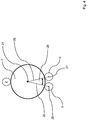
- Fig. 1 shows a schematic side view of an apparatus according to an embodiment.
- the apparatus comprises a handling device 1 and a friction wheel 2.
- the handling device 1 comprises three holding means 3 for holding a pharmaceutical container 4 made of glass or of a polymer.
- the container 4 has a circular cross section and is at least in this region cylindrically formed.
- the holding means 3 each comprise a first support wheel 5, a second support wheel 6 and a suction element 7.
- the holding means 3 are configured for holding the container 4 on its lateral surface.
- the handling device 1 is rotatable such that the container 4 can first be transferred from a first transfer position 9 into an inspection area 10 and second from the inspection area 10 into a second transfer position 11.
- the holding means 3, respectively the handling device 1, and/or the friction wheel 2 are movable to and fro a first axis 21 such that the container 4 being located in the inspection area 10 can be brought into contact with the friction wheel 2.
- the friction wheel 2 is in contact with the container 4, i.e. in the inspection position, the container can be rotated around its longitudinal axis 24, for example by rotation the friction wheel 2. Therefore, the whole surface of the container 4 can be inspected.
- the handling device 1 is rotated further, such that the container 4 is transferred into the second transfer position 11.
- Figure 1 further shows that the three holding means 3 are arranged on a circle with an angle of 120° from each other.
- Figure 2 shows a schematic side view of an apparatus according to another embodiment.
- the apparatus comprises a handling device 1 and a friction wheel 2 as described with regard to figure 1 .
- the apparatus comprises a transportation device 12, i.e. a conveyor belt, a first transfer device 13 and a second transfer device 14.
- the transportation device 12 is configured to transport the container 4 to the first transfer device 13 and further receives the container 4 from the second transfer device 14.
- the first transfer device 13 is configured to take the container 4 from the transportation device 12 and to transfer it into a first transfer position 9.
- the first transfer device 13 comprises three holding arrangements 15 for holding the container 4, preferably on its lateral surface.
- each holding arrangement 15 comprises a suction element 16 for securely holding the container 4.
- the first transfer device 13 is rotatable as indicated by arrow 17A such that the container 4 can be transferred into said first transfer position 9.
- the second transfer device 14 is configured to receive the container 4 from the handling device 1. Further, the second transfer device 14 comprises three holding arrangements 18 for holding the container 4, preferably on its lateral surface. The second transfer device 14 is rotatable as indicated by arrow 17B such that the container 4 can be transferred from the second transfer position 11 onto the transportation device 12. Preferably, the container 4 is positioned with its lateral surface on the transportation device 12. Each of the holding arrangements 18 comprise a suction element 19 for securely holding the container 4.
- Figure 2 further shows that the handling device 1, the first transfer device 13 and the second transfer device 14 are positioned on the same structure 20, for example a board, such that the devices are all together movable to and fro the axis 21.
- first handling device 13 is movable to and fro a second axis 22 and the second handling device 14 is movable to and fro a third axis 23.
- the first axis 21 and the second axis 22 intersect at an angle of about 45°.
- first axis 21 and the third axis 23 intersect at an angle of about 45°.
- the holding arrangements 15 of the first transfer device 13 are arranged on a circle with an angle of 120° to each other.
- the holding arrangements 18 of the second transfer device 14 are arranged on a circle with an angle of 120° to each other.
- FIG. 3 shows a schematic side view of an apparatus according to another embodiment.
- the apparatus comprises a handling device 1 and a friction wheel 2.
- this handling device 1 only comprises two holding means 3.
- Each of the holding means 3 comprises a first support wheel 5, a second support wheel 6 and a suction element 7.
- the handling device 1 is rotatable such that a container 4 can first be transferred from a first transfer position 9 into an inspection area 10.
- the holding means 3 respectively the handling device 1, and/or the friction wheel 2 are movable to and fro a first axis 21.
- the handling device 1 is rotated for bringing the container from the inspection area 10 into a second transfer position 11, which is identical with the first transfer position 9.
- the holding means 3 respectively the handling device 1 and/or the friction wheel 2 are described as being movable along a first axis 21 the movement does not have to be a linear movement. It is also possible that these components fulfil a no-linear movement.
- fig. 4 serves to illustrate the arrangement of the first support wheel 5 and the second support wheel 6 to each other.
- Fig. 4 shows a container 4 being supported by the first support wheel 5 and the second support wheel 6.
- the rotational axis 25 of said first support wheel 5 and the longitudinal axis 24 of the container 4 define a first plane 26.
- the rotational axis 27 of the second support wheel 6 and said longitudinal axis 24 of the container 4 define a second plane 28.
- the first plane 26 and said second plane 28 intersect at an angle 29.
- the angle 29 ranges from 45° to less than 120°, preferably 50° to 90°, more preferably of 60° to 80°, more preferably of 65° to 75°, most preferably at an angle of about 70°.
- the position of longitudinal axis 24 depends on the diameter of the container. Hence, when the apparatus is used for container with different diameter, the position of the first and second support wheels 5, 6 has to be adapted.
- All of the embodiments described in fig. 1 to 3 may comprise holding means 3 with a first support wheel 5 and a second support wheel 6 that are arranged such that the angle 29 lies within the above mentioned ranges.
Landscapes
- Chemical & Material Sciences (AREA)
- Health & Medical Sciences (AREA)
- Life Sciences & Earth Sciences (AREA)
- Immunology (AREA)
- Analytical Chemistry (AREA)
- Biochemistry (AREA)
- General Health & Medical Sciences (AREA)
- General Physics & Mathematics (AREA)
- Physics & Mathematics (AREA)
- Pathology (AREA)
- Engineering & Computer Science (AREA)
- Robotics (AREA)
- Mechanical Engineering (AREA)
- Food Science & Technology (AREA)
- Medicinal Chemistry (AREA)
- Specific Conveyance Elements (AREA)
- Investigating Materials By The Use Of Optical Means Adapted For Particular Applications (AREA)
Priority Applications (5)
| Application Number | Priority Date | Filing Date | Title |
|---|---|---|---|
| EP19200221.0A EP3797883B1 (de) | 2019-09-27 | 2019-09-27 | Vorrichtung zur inspektion eines pharmazeutischen behälters |
| CN202010640398.0A CN112577899A (zh) | 2019-09-27 | 2020-07-06 | 用于检查药品容器的设备 |
| JP2020121142A JP7606827B2 (ja) | 2019-09-27 | 2020-07-15 | 医薬品容器を検査するための装置 |
| US17/032,652 US11933798B2 (en) | 2019-09-27 | 2020-09-25 | Apparatus for inspecting pharmaceutical containers |
| JP2024167387A JP2024177201A (ja) | 2019-09-27 | 2024-09-26 | 医薬品容器を検査するための装置 |
Applications Claiming Priority (1)
| Application Number | Priority Date | Filing Date | Title |
|---|---|---|---|
| EP19200221.0A EP3797883B1 (de) | 2019-09-27 | 2019-09-27 | Vorrichtung zur inspektion eines pharmazeutischen behälters |
Publications (2)
| Publication Number | Publication Date |
|---|---|
| EP3797883A1 true EP3797883A1 (de) | 2021-03-31 |
| EP3797883B1 EP3797883B1 (de) | 2022-06-08 |
Family
ID=68165435
Family Applications (1)
| Application Number | Title | Priority Date | Filing Date |
|---|---|---|---|
| EP19200221.0A Active EP3797883B1 (de) | 2019-09-27 | 2019-09-27 | Vorrichtung zur inspektion eines pharmazeutischen behälters |
Country Status (4)
| Country | Link |
|---|---|
| US (1) | US11933798B2 (de) |
| EP (1) | EP3797883B1 (de) |
| JP (2) | JP7606827B2 (de) |
| CN (1) | CN112577899A (de) |
Cited By (4)
| Publication number | Priority date | Publication date | Assignee | Title |
|---|---|---|---|---|
| US11841327B2 (en) | 2020-01-23 | 2023-12-12 | Schott Pharma Schweiz Ag | Detection and characterization of defects in pharmaceutical cylindrical containers |
| US11921128B2 (en) | 2019-09-27 | 2024-03-05 | Schott Pharma Schweiz Ag | Apparatus for inspecting pharmaceutical containers |
| US11933798B2 (en) | 2019-09-27 | 2024-03-19 | Schott Pharma Schweiz Ag | Apparatus for inspecting pharmaceutical containers |
| US12259337B2 (en) | 2020-01-23 | 2025-03-25 | Schott Pharma Schweiz Ag | Detection and characterization of defects in pharmaceutical cylindrical containers |
Families Citing this family (1)
| Publication number | Priority date | Publication date | Assignee | Title |
|---|---|---|---|---|
| CN117101912B (zh) * | 2023-10-16 | 2023-12-15 | 山东龙口三元铝材有限公司 | 一种易拉罐两涂合并喷涂装置 |
Citations (7)
| Publication number | Priority date | Publication date | Assignee | Title |
|---|---|---|---|---|
| US4378493A (en) * | 1980-11-03 | 1983-03-29 | Owens-Illinois, Inc. | Glass container sidewall defect detection system with a diffused and controlled light source |
| JPH0336949U (de) * | 1989-08-21 | 1991-04-10 | ||
| JP2000214104A (ja) * | 1999-01-26 | 2000-08-04 | Precision:Kk | ガラス壜口部の欠陥検査装置 |
| US20100095790A1 (en) * | 2008-10-18 | 2010-04-22 | Raupp Henry F | Modular Apparatus And Method For Rotating Glass Containers And The Like |
| DE102011113670A1 (de) | 2011-09-20 | 2013-03-21 | Schott Ag | Beleuchtungsvorrichtung, Inspektionsvorrichtung und Inspektionsverfahren für die optische Prüfung eines Objekts |
| JP2015169449A (ja) * | 2014-03-04 | 2015-09-28 | 東洋ガラス機械株式会社 | ガラスびんの胴径測定器 |
| DE102016114190A1 (de) | 2016-08-01 | 2018-02-01 | Schott Schweiz Ag | Verfahren und Vorrichtung zur optischen Untersuchung transparenter Körper |
Family Cites Families (42)
| Publication number | Priority date | Publication date | Assignee | Title |
|---|---|---|---|---|
| US2531529A (en) * | 1949-09-30 | 1950-11-28 | Rca Corp | Inspection apparatus and method |
| JPS5228432B2 (de) * | 1973-10-29 | 1977-07-26 | ||
| JPS5819543A (ja) * | 1981-07-28 | 1983-02-04 | Mitsubishi Electric Corp | 検壜装置 |
| JPH0450254Y2 (de) * | 1986-01-29 | 1992-11-26 | ||
| JPH0336949A (ja) | 1989-06-30 | 1991-02-18 | Mitsubishi Electric Corp | 偏平型ブラシレスdcモータ |
| JPH0725683Y2 (ja) * | 1989-08-21 | 1995-06-07 | 三共株式会社 | バイアル瓶の外観自動検査装置 |
| JPH07130814A (ja) | 1993-10-29 | 1995-05-19 | Sony Corp | Icパッケージの外観検査装置 |
| US5917588A (en) | 1996-11-04 | 1999-06-29 | Kla-Tencor Corporation | Automated specimen inspection system for and method of distinguishing features or anomalies under either bright field or dark field illumination |
| JP3445722B2 (ja) | 1997-05-14 | 2003-09-08 | 出光石油化学株式会社 | 表面検査装置および表面検査方法 |
| CA2252308C (en) | 1998-10-30 | 2005-01-04 | Image Processing Systems, Inc. | Glass inspection system |
| US20130084594A1 (en) | 2002-10-03 | 2013-04-04 | Battelle Memorial Institute | Drug susceptibility using rare cell detection system |
| WO2004036198A1 (ja) | 2002-10-18 | 2004-04-29 | Kirin Techno-System Corporation | ガラス壜の検査装置における基準画像の作成方法及び装置 |
| US7414786B2 (en) | 2004-01-12 | 2008-08-19 | University Of Rochester | System and method converting the polarization state of an optical beam into an inhomogeneously polarized state |
| JP2005227257A (ja) | 2004-01-16 | 2005-08-25 | Nakagami Corporation:Kk | 円筒型容器の外周面検査装置 |
| JP4724182B2 (ja) | 2004-07-30 | 2011-07-13 | イーグル・ヴィジョン・システムズ・ベスローテン・フェンノートシャップ | 容器を検査する方法及び装置 |
| US7414716B2 (en) | 2006-10-23 | 2008-08-19 | Emhart Glass S.A. | Machine for inspecting glass containers |
| US7551274B1 (en) | 2007-02-28 | 2009-06-23 | Lite Sentry Corporation | Defect detection lighting system and methods for large glass sheets |
| JP5060808B2 (ja) | 2007-03-27 | 2012-10-31 | オリンパス株式会社 | 外観検査装置 |
| US7800749B2 (en) | 2007-05-31 | 2010-09-21 | Corning Incorporated | Inspection technique for transparent substrates |
| US20100118136A1 (en) | 2007-06-13 | 2010-05-13 | Riet Jan Arie Pieter Van | Surface inspection device and an arrangement for inspecting a surface |
| DE102008029661A1 (de) | 2008-06-24 | 2009-12-31 | Khs Ag | Redundante Inspektion |
| JP5196174B2 (ja) * | 2008-09-18 | 2013-05-15 | キリンテクノシステム株式会社 | 吸引式壜台、並びにこれを用いた容器搬送装置及び容器検査装置 |
| JP5388543B2 (ja) | 2008-11-05 | 2014-01-15 | キヤノン株式会社 | 外観検査装置 |
| BR112012015733A2 (pt) | 2009-12-23 | 2019-04-24 | Colgate Palmolive Co | composições visualmente padronizadas e orientadas |
| US20130162986A1 (en) | 2010-05-04 | 2013-06-27 | Sanofi-Aventis Deutschland Gmbh | Device and method for detection of defects in vitreous bodies |
| JP6060010B2 (ja) | 2013-03-07 | 2017-01-11 | シスメックス株式会社 | 検体処理装置および検体処理方法 |
| CN104458760B (zh) | 2013-09-13 | 2018-04-27 | 楚天科技股份有限公司 | 自动灯检机异物检测装置 |
| CN203949879U (zh) * | 2014-05-12 | 2014-11-19 | 双峰格雷斯海姆医药玻璃(丹阳)有限公司 | 玻璃瓶在线检测系统 |
| DE102014008596B4 (de) | 2014-06-10 | 2016-01-28 | Grenzebach Maschinenbau Gmbh | Vorrichtung und Verfahren zur schnellen und sicheren Messung von Verzerrungsfehlern in einem produzierten Floatglas - Band |
| DE102014216188A1 (de) | 2014-08-14 | 2016-02-18 | Krones Ag | Optisches Inspektionsverfahren und optische Inspektionsvorrichtung für Behälter |
| KR20160022962A (ko) | 2014-08-20 | 2016-03-03 | 한국항공우주연구원 | 표면 검사장치 및 표면 검사방법 |
| DE102014226965A1 (de) | 2014-12-23 | 2016-06-23 | Krones Ag | Vorrichtung und Verfahren zur fortlaufenden Inspektion von Behältern |
| US20160231555A1 (en) | 2015-02-09 | 2016-08-11 | Visicon Technologies, Inc. | Borescope Inspection System |
| JP2017040510A (ja) | 2015-08-18 | 2017-02-23 | キヤノン株式会社 | 検査装置、検査方法および物体製造方法 |
| US10845316B2 (en) * | 2015-10-21 | 2020-11-24 | Tiama | Method and apparatus for optically inspecting the profile of containers, the profile including the bottom |
| US10337977B1 (en) | 2016-11-22 | 2019-07-02 | Corning Incorporated | Systems and methods for glass particle detection |
| DE102017008406B4 (de) | 2017-09-07 | 2023-07-20 | Heuft Systemtechnik Gmbh | Inspektionsvorrichtung und ein Verfahren mit Farbbeleuchtung |
| DE102018110749B3 (de) | 2018-05-04 | 2019-08-14 | Matthews International GmbH | Verfahren zum Überprüfen eines Druckzylinders und eine entsprechende Anordnung |
| EP3797883B1 (de) | 2019-09-27 | 2022-06-08 | SCHOTT Schweiz AG | Vorrichtung zur inspektion eines pharmazeutischen behälters |
| EP3798621B1 (de) | 2019-09-27 | 2022-11-23 | SCHOTT Schweiz AG | Vorrichtung zur inspektion eines pharmazeutischen behälters |
| EP3855173A1 (de) | 2020-01-23 | 2021-07-28 | SCHOTT Schweiz AG | Detektion und charakterisierung von defekten in pharmazeutischen zylindrischen behältern |
| EP3855174B1 (de) | 2020-01-23 | 2024-05-15 | SCHOTT Pharma Schweiz AG | Detektion und charakterisierung von defekten in pharmazeutischen zylindrischen behältern |
-
2019
- 2019-09-27 EP EP19200221.0A patent/EP3797883B1/de active Active
-
2020
- 2020-07-06 CN CN202010640398.0A patent/CN112577899A/zh active Pending
- 2020-07-15 JP JP2020121142A patent/JP7606827B2/ja active Active
- 2020-09-25 US US17/032,652 patent/US11933798B2/en active Active
-
2024
- 2024-09-26 JP JP2024167387A patent/JP2024177201A/ja not_active Withdrawn
Patent Citations (7)
| Publication number | Priority date | Publication date | Assignee | Title |
|---|---|---|---|---|
| US4378493A (en) * | 1980-11-03 | 1983-03-29 | Owens-Illinois, Inc. | Glass container sidewall defect detection system with a diffused and controlled light source |
| JPH0336949U (de) * | 1989-08-21 | 1991-04-10 | ||
| JP2000214104A (ja) * | 1999-01-26 | 2000-08-04 | Precision:Kk | ガラス壜口部の欠陥検査装置 |
| US20100095790A1 (en) * | 2008-10-18 | 2010-04-22 | Raupp Henry F | Modular Apparatus And Method For Rotating Glass Containers And The Like |
| DE102011113670A1 (de) | 2011-09-20 | 2013-03-21 | Schott Ag | Beleuchtungsvorrichtung, Inspektionsvorrichtung und Inspektionsverfahren für die optische Prüfung eines Objekts |
| JP2015169449A (ja) * | 2014-03-04 | 2015-09-28 | 東洋ガラス機械株式会社 | ガラスびんの胴径測定器 |
| DE102016114190A1 (de) | 2016-08-01 | 2018-02-01 | Schott Schweiz Ag | Verfahren und Vorrichtung zur optischen Untersuchung transparenter Körper |
Cited By (4)
| Publication number | Priority date | Publication date | Assignee | Title |
|---|---|---|---|---|
| US11921128B2 (en) | 2019-09-27 | 2024-03-05 | Schott Pharma Schweiz Ag | Apparatus for inspecting pharmaceutical containers |
| US11933798B2 (en) | 2019-09-27 | 2024-03-19 | Schott Pharma Schweiz Ag | Apparatus for inspecting pharmaceutical containers |
| US11841327B2 (en) | 2020-01-23 | 2023-12-12 | Schott Pharma Schweiz Ag | Detection and characterization of defects in pharmaceutical cylindrical containers |
| US12259337B2 (en) | 2020-01-23 | 2025-03-25 | Schott Pharma Schweiz Ag | Detection and characterization of defects in pharmaceutical cylindrical containers |
Also Published As
| Publication number | Publication date |
|---|---|
| JP2024177201A (ja) | 2024-12-19 |
| JP7606827B2 (ja) | 2024-12-26 |
| CN112577899A (zh) | 2021-03-30 |
| US20210096144A1 (en) | 2021-04-01 |
| US11933798B2 (en) | 2024-03-19 |
| JP2021054653A (ja) | 2021-04-08 |
| EP3797883B1 (de) | 2022-06-08 |
Similar Documents
| Publication | Publication Date | Title |
|---|---|---|
| EP3797883B1 (de) | Vorrichtung zur inspektion eines pharmazeutischen behälters | |
| US11921128B2 (en) | Apparatus for inspecting pharmaceutical containers | |
| US9085420B2 (en) | Orienting apparatus and method | |
| WO2005031328A1 (ja) | 検査システム | |
| RU2009122363A (ru) | Способ проверки или контроля бутылок или подобных сосудов, а также устройство для проверки бутылок или подобных сосудов | |
| JPH0562943B2 (de) | ||
| WO2019202726A1 (ja) | 搬送物品選別装置 | |
| JPWO2015146628A1 (ja) | 搬送システム及び被搬送品検査システム | |
| JP6054769B2 (ja) | 測定容器供給装置 | |
| EP3848701B1 (de) | Inspektionsvorrichtung für zylindrische körper | |
| JP6107478B2 (ja) | 泡除去装置 | |
| JPH0535986B2 (de) | ||
| JP3625443B2 (ja) | びんの肉厚計測装置および肉厚計測方法 | |
| CN104931511A (zh) | 检查装置 | |
| EP1493694A2 (de) | Führungsschiene für einen Behälterinspektionsvorrichtung | |
| JP4236886B2 (ja) | 製品検査方法及び装置 | |
| JPS62239008A (ja) | 頭付き部品の検査機用搬送装置 | |
| JP4629122B2 (ja) | 製品検査方法及び装置 | |
| WO2024104745A1 (en) | A system and method for the inspection of cylindrical containers | |
| CN112295938A (zh) | 一种基于双远心镜头检测尺寸视觉设备及其使用方法 | |
| US20260029353A1 (en) | Method and Device for Inspecting the Base of a Container | |
| JP7086439B1 (ja) | 容器検査装置 | |
| JP2013049523A (ja) | 物品の搬送装置及び搬送方法 | |
| JP5194228B2 (ja) | 吸引式壜台、及びこれを用いた容器搬送装置並びに容器検査装置 | |
| JP2015017911A (ja) | 観察支援装置および検査装置 |
Legal Events
| Date | Code | Title | Description |
|---|---|---|---|
| STAA | Information on the status of an ep patent application or granted ep patent |
Free format text: STATUS: EXAMINATION IS IN PROGRESS |
|
| PUAI | Public reference made under article 153(3) epc to a published international application that has entered the european phase |
Free format text: ORIGINAL CODE: 0009012 |
|
| 17P | Request for examination filed |
Effective date: 20191004 |
|
| AK | Designated contracting states |
Kind code of ref document: A1 Designated state(s): AL AT BE BG CH CY CZ DE DK EE ES FI FR GB GR HR HU IE IS IT LI LT LU LV MC MK MT NL NO PL PT RO RS SE SI SK SM TR |
|
| AX | Request for extension of the european patent |
Extension state: BA ME |
|
| R17C | First examination report despatched (corrected) |
Effective date: 20200612 |
|
| TPAC | Observations filed by third parties |
Free format text: ORIGINAL CODE: EPIDOSNTIPA |
|
| GRAP | Despatch of communication of intention to grant a patent |
Free format text: ORIGINAL CODE: EPIDOSNIGR1 |
|
| STAA | Information on the status of an ep patent application or granted ep patent |
Free format text: STATUS: GRANT OF PATENT IS INTENDED |
|
| INTG | Intention to grant announced |
Effective date: 20220302 |
|
| GRAS | Grant fee paid |
Free format text: ORIGINAL CODE: EPIDOSNIGR3 |
|
| GRAA | (expected) grant |
Free format text: ORIGINAL CODE: 0009210 |
|
| STAA | Information on the status of an ep patent application or granted ep patent |
Free format text: STATUS: THE PATENT HAS BEEN GRANTED |
|
| AK | Designated contracting states |
Kind code of ref document: B1 Designated state(s): AL AT BE BG CH CY CZ DE DK EE ES FI FR GB GR HR HU IE IS IT LI LT LU LV MC MK MT NL NO PL PT RO RS SE SI SK SM TR |
|
| REG | Reference to a national code |
Ref country code: AT Ref legal event code: REF Ref document number: 1496555 Country of ref document: AT Kind code of ref document: T Effective date: 20220615 Ref country code: CH Ref legal event code: EP |
|
| REG | Reference to a national code |
Ref country code: DE Ref legal event code: R096 Ref document number: 602019015617 Country of ref document: DE |
|
| REG | Reference to a national code |
Ref country code: IE Ref legal event code: FG4D |
|
| REG | Reference to a national code |
Ref country code: LT Ref legal event code: MG9D |
|
| REG | Reference to a national code |
Ref country code: NL Ref legal event code: MP Effective date: 20220608 |
|
| PG25 | Lapsed in a contracting state [announced via postgrant information from national office to epo] |
Ref country code: SE Free format text: LAPSE BECAUSE OF FAILURE TO SUBMIT A TRANSLATION OF THE DESCRIPTION OR TO PAY THE FEE WITHIN THE PRESCRIBED TIME-LIMIT Effective date: 20220608 Ref country code: NO Free format text: LAPSE BECAUSE OF FAILURE TO SUBMIT A TRANSLATION OF THE DESCRIPTION OR TO PAY THE FEE WITHIN THE PRESCRIBED TIME-LIMIT Effective date: 20220908 Ref country code: LT Free format text: LAPSE BECAUSE OF FAILURE TO SUBMIT A TRANSLATION OF THE DESCRIPTION OR TO PAY THE FEE WITHIN THE PRESCRIBED TIME-LIMIT Effective date: 20220608 Ref country code: HR Free format text: LAPSE BECAUSE OF FAILURE TO SUBMIT A TRANSLATION OF THE DESCRIPTION OR TO PAY THE FEE WITHIN THE PRESCRIBED TIME-LIMIT Effective date: 20220608 Ref country code: GR Free format text: LAPSE BECAUSE OF FAILURE TO SUBMIT A TRANSLATION OF THE DESCRIPTION OR TO PAY THE FEE WITHIN THE PRESCRIBED TIME-LIMIT Effective date: 20220909 Ref country code: FI Free format text: LAPSE BECAUSE OF FAILURE TO SUBMIT A TRANSLATION OF THE DESCRIPTION OR TO PAY THE FEE WITHIN THE PRESCRIBED TIME-LIMIT Effective date: 20220608 Ref country code: BG Free format text: LAPSE BECAUSE OF FAILURE TO SUBMIT A TRANSLATION OF THE DESCRIPTION OR TO PAY THE FEE WITHIN THE PRESCRIBED TIME-LIMIT Effective date: 20220908 |
|
| REG | Reference to a national code |
Ref country code: AT Ref legal event code: MK05 Ref document number: 1496555 Country of ref document: AT Kind code of ref document: T Effective date: 20220608 |
|
| PG25 | Lapsed in a contracting state [announced via postgrant information from national office to epo] |
Ref country code: RS Free format text: LAPSE BECAUSE OF FAILURE TO SUBMIT A TRANSLATION OF THE DESCRIPTION OR TO PAY THE FEE WITHIN THE PRESCRIBED TIME-LIMIT Effective date: 20220608 Ref country code: LV Free format text: LAPSE BECAUSE OF FAILURE TO SUBMIT A TRANSLATION OF THE DESCRIPTION OR TO PAY THE FEE WITHIN THE PRESCRIBED TIME-LIMIT Effective date: 20220608 |
|
| PG25 | Lapsed in a contracting state [announced via postgrant information from national office to epo] |
Ref country code: NL Free format text: LAPSE BECAUSE OF FAILURE TO SUBMIT A TRANSLATION OF THE DESCRIPTION OR TO PAY THE FEE WITHIN THE PRESCRIBED TIME-LIMIT Effective date: 20220608 |
|
| RAP4 | Party data changed (patent owner data changed or rights of a patent transferred) |
Owner name: SCHOTT PHARMA SCHWEIZ AG |
|
| PG25 | Lapsed in a contracting state [announced via postgrant information from national office to epo] |
Ref country code: SM Free format text: LAPSE BECAUSE OF FAILURE TO SUBMIT A TRANSLATION OF THE DESCRIPTION OR TO PAY THE FEE WITHIN THE PRESCRIBED TIME-LIMIT Effective date: 20220608 Ref country code: SK Free format text: LAPSE BECAUSE OF FAILURE TO SUBMIT A TRANSLATION OF THE DESCRIPTION OR TO PAY THE FEE WITHIN THE PRESCRIBED TIME-LIMIT Effective date: 20220608 Ref country code: RO Free format text: LAPSE BECAUSE OF FAILURE TO SUBMIT A TRANSLATION OF THE DESCRIPTION OR TO PAY THE FEE WITHIN THE PRESCRIBED TIME-LIMIT Effective date: 20220608 Ref country code: PT Free format text: LAPSE BECAUSE OF FAILURE TO SUBMIT A TRANSLATION OF THE DESCRIPTION OR TO PAY THE FEE WITHIN THE PRESCRIBED TIME-LIMIT Effective date: 20221010 Ref country code: ES Free format text: LAPSE BECAUSE OF FAILURE TO SUBMIT A TRANSLATION OF THE DESCRIPTION OR TO PAY THE FEE WITHIN THE PRESCRIBED TIME-LIMIT Effective date: 20220608 Ref country code: EE Free format text: LAPSE BECAUSE OF FAILURE TO SUBMIT A TRANSLATION OF THE DESCRIPTION OR TO PAY THE FEE WITHIN THE PRESCRIBED TIME-LIMIT Effective date: 20220608 Ref country code: CZ Free format text: LAPSE BECAUSE OF FAILURE TO SUBMIT A TRANSLATION OF THE DESCRIPTION OR TO PAY THE FEE WITHIN THE PRESCRIBED TIME-LIMIT Effective date: 20220608 Ref country code: AT Free format text: LAPSE BECAUSE OF FAILURE TO SUBMIT A TRANSLATION OF THE DESCRIPTION OR TO PAY THE FEE WITHIN THE PRESCRIBED TIME-LIMIT Effective date: 20220608 |
|
| REG | Reference to a national code |
Ref country code: BE Ref legal event code: PD Owner name: SCHOTT PHARMA SCHWEIZ AG; CH Free format text: DETAILS ASSIGNMENT: CHANGE OF OWNER(S), MERGE; FORMER OWNER NAME: SCHOTT SCHWEIZ AG Effective date: 20221222 |
|
| PG25 | Lapsed in a contracting state [announced via postgrant information from national office to epo] |
Ref country code: PL Free format text: LAPSE BECAUSE OF FAILURE TO SUBMIT A TRANSLATION OF THE DESCRIPTION OR TO PAY THE FEE WITHIN THE PRESCRIBED TIME-LIMIT Effective date: 20220608 Ref country code: IS Free format text: LAPSE BECAUSE OF FAILURE TO SUBMIT A TRANSLATION OF THE DESCRIPTION OR TO PAY THE FEE WITHIN THE PRESCRIBED TIME-LIMIT Effective date: 20221008 |
|
| REG | Reference to a national code |
Ref country code: DE Ref legal event code: R081 Ref document number: 602019015617 Country of ref document: DE Owner name: SCHOTT PHARMA SCHWEIZ AG, CH Free format text: FORMER OWNER: SCHOTT SCHWEIZ AG, ST. GALLEN, CH |
|
| REG | Reference to a national code |
Ref country code: DE Ref legal event code: R097 Ref document number: 602019015617 Country of ref document: DE |
|
| PG25 | Lapsed in a contracting state [announced via postgrant information from national office to epo] |
Ref country code: AL Free format text: LAPSE BECAUSE OF FAILURE TO SUBMIT A TRANSLATION OF THE DESCRIPTION OR TO PAY THE FEE WITHIN THE PRESCRIBED TIME-LIMIT Effective date: 20220608 |
|
| PLBE | No opposition filed within time limit |
Free format text: ORIGINAL CODE: 0009261 |
|
| STAA | Information on the status of an ep patent application or granted ep patent |
Free format text: STATUS: NO OPPOSITION FILED WITHIN TIME LIMIT |
|
| PG25 | Lapsed in a contracting state [announced via postgrant information from national office to epo] |
Ref country code: MC Free format text: LAPSE BECAUSE OF FAILURE TO SUBMIT A TRANSLATION OF THE DESCRIPTION OR TO PAY THE FEE WITHIN THE PRESCRIBED TIME-LIMIT Effective date: 20220608 Ref country code: DK Free format text: LAPSE BECAUSE OF FAILURE TO SUBMIT A TRANSLATION OF THE DESCRIPTION OR TO PAY THE FEE WITHIN THE PRESCRIBED TIME-LIMIT Effective date: 20220608 |
|
| 26N | No opposition filed |
Effective date: 20230310 |
|
| PG25 | Lapsed in a contracting state [announced via postgrant information from national office to epo] |
Ref country code: SI Free format text: LAPSE BECAUSE OF FAILURE TO SUBMIT A TRANSLATION OF THE DESCRIPTION OR TO PAY THE FEE WITHIN THE PRESCRIBED TIME-LIMIT Effective date: 20220608 |
|
| P01 | Opt-out of the competence of the unified patent court (upc) registered |
Effective date: 20230512 |
|
| PG25 | Lapsed in a contracting state [announced via postgrant information from national office to epo] |
Ref country code: LU Free format text: LAPSE BECAUSE OF NON-PAYMENT OF DUE FEES Effective date: 20220927 |
|
| PG25 | Lapsed in a contracting state [announced via postgrant information from national office to epo] |
Ref country code: IE Free format text: LAPSE BECAUSE OF NON-PAYMENT OF DUE FEES Effective date: 20220927 |
|
| PG25 | Lapsed in a contracting state [announced via postgrant information from national office to epo] |
Ref country code: CY Free format text: LAPSE BECAUSE OF FAILURE TO SUBMIT A TRANSLATION OF THE DESCRIPTION OR TO PAY THE FEE WITHIN THE PRESCRIBED TIME-LIMIT Effective date: 20220608 |
|
| GBPC | Gb: european patent ceased through non-payment of renewal fee |
Effective date: 20230927 |
|
| PG25 | Lapsed in a contracting state [announced via postgrant information from national office to epo] |
Ref country code: MK Free format text: LAPSE BECAUSE OF FAILURE TO SUBMIT A TRANSLATION OF THE DESCRIPTION OR TO PAY THE FEE WITHIN THE PRESCRIBED TIME-LIMIT Effective date: 20220608 Ref country code: HU Free format text: LAPSE BECAUSE OF FAILURE TO SUBMIT A TRANSLATION OF THE DESCRIPTION OR TO PAY THE FEE WITHIN THE PRESCRIBED TIME-LIMIT; INVALID AB INITIO Effective date: 20190927 |
|
| PG25 | Lapsed in a contracting state [announced via postgrant information from national office to epo] |
Ref country code: GB Free format text: LAPSE BECAUSE OF NON-PAYMENT OF DUE FEES Effective date: 20230927 |
|
| PG25 | Lapsed in a contracting state [announced via postgrant information from national office to epo] |
Ref country code: GB Free format text: LAPSE BECAUSE OF NON-PAYMENT OF DUE FEES Effective date: 20230927 |
|
| PG25 | Lapsed in a contracting state [announced via postgrant information from national office to epo] |
Ref country code: MT Free format text: LAPSE BECAUSE OF FAILURE TO SUBMIT A TRANSLATION OF THE DESCRIPTION OR TO PAY THE FEE WITHIN THE PRESCRIBED TIME-LIMIT Effective date: 20220608 |
|
| PG25 | Lapsed in a contracting state [announced via postgrant information from national office to epo] |
Ref country code: BG Free format text: LAPSE BECAUSE OF FAILURE TO SUBMIT A TRANSLATION OF THE DESCRIPTION OR TO PAY THE FEE WITHIN THE PRESCRIBED TIME-LIMIT Effective date: 20220608 |
|
| PG25 | Lapsed in a contracting state [announced via postgrant information from national office to epo] |
Ref country code: BG Free format text: LAPSE BECAUSE OF FAILURE TO SUBMIT A TRANSLATION OF THE DESCRIPTION OR TO PAY THE FEE WITHIN THE PRESCRIBED TIME-LIMIT Effective date: 20220608 |
|
| REG | Reference to a national code |
Ref country code: CH Ref legal event code: U11 Free format text: ST27 STATUS EVENT CODE: U-0-0-U10-U11 (AS PROVIDED BY THE NATIONAL OFFICE) Effective date: 20251001 |
|
| PGFP | Annual fee paid to national office [announced via postgrant information from national office to epo] |
Ref country code: DE Payment date: 20250919 Year of fee payment: 7 |
|
| PGFP | Annual fee paid to national office [announced via postgrant information from national office to epo] |
Ref country code: IT Payment date: 20250923 Year of fee payment: 7 |
|
| PGFP | Annual fee paid to national office [announced via postgrant information from national office to epo] |
Ref country code: BE Payment date: 20250918 Year of fee payment: 7 |
|
| PGFP | Annual fee paid to national office [announced via postgrant information from national office to epo] |
Ref country code: FR Payment date: 20250922 Year of fee payment: 7 |
|
| PG25 | Lapsed in a contracting state [announced via postgrant information from national office to epo] |
Ref country code: TR Free format text: LAPSE BECAUSE OF FAILURE TO SUBMIT A TRANSLATION OF THE DESCRIPTION OR TO PAY THE FEE WITHIN THE PRESCRIBED TIME-LIMIT Effective date: 20220608 |
|
| PGFP | Annual fee paid to national office [announced via postgrant information from national office to epo] |
Ref country code: CH Payment date: 20251001 Year of fee payment: 7 |