EP3848701B1 - Inspektionsvorrichtung für zylindrische körper - Google Patents
Inspektionsvorrichtung für zylindrische körper Download PDFInfo
- Publication number
- EP3848701B1 EP3848701B1 EP20150706.8A EP20150706A EP3848701B1 EP 3848701 B1 EP3848701 B1 EP 3848701B1 EP 20150706 A EP20150706 A EP 20150706A EP 3848701 B1 EP3848701 B1 EP 3848701B1
- Authority
- EP
- European Patent Office
- Prior art keywords
- cylindrical body
- plane
- rotation
- transport
- less
- Prior art date
- Legal status (The legal status is an assumption and is not a legal conclusion. Google has not performed a legal analysis and makes no representation as to the accuracy of the status listed.)
- Active
Links
Images
Classifications
-
- G—PHYSICS
- G01—MEASURING; TESTING
- G01B—MEASURING LENGTH, THICKNESS OR SIMILAR LINEAR DIMENSIONS; MEASURING ANGLES; MEASURING AREAS; MEASURING IRREGULARITIES OF SURFACES OR CONTOURS
- G01B11/00—Measuring arrangements characterised by the use of optical techniques
-
- G—PHYSICS
- G01—MEASURING; TESTING
- G01N—INVESTIGATING OR ANALYSING MATERIALS BY DETERMINING THEIR CHEMICAL OR PHYSICAL PROPERTIES
- G01N21/00—Investigating or analysing materials by the use of optical means, i.e. using sub-millimetre waves, infrared, visible or ultraviolet light
- G01N21/84—Systems specially adapted for particular applications
- G01N21/88—Investigating the presence of flaws or contamination
- G01N21/95—Investigating the presence of flaws or contamination characterised by the material or shape of the object to be examined
- G01N21/952—Inspecting the exterior surface of cylindrical bodies or wires
-
- G—PHYSICS
- G01—MEASURING; TESTING
- G01B—MEASURING LENGTH, THICKNESS OR SIMILAR LINEAR DIMENSIONS; MEASURING ANGLES; MEASURING AREAS; MEASURING IRREGULARITIES OF SURFACES OR CONTOURS
- G01B11/00—Measuring arrangements characterised by the use of optical techniques
- G01B11/24—Measuring arrangements characterised by the use of optical techniques for measuring contours or curvatures
- G01B11/2408—Measuring arrangements characterised by the use of optical techniques for measuring contours or curvatures for measuring roundness
-
- G—PHYSICS
- G01—MEASURING; TESTING
- G01B—MEASURING LENGTH, THICKNESS OR SIMILAR LINEAR DIMENSIONS; MEASURING ANGLES; MEASURING AREAS; MEASURING IRREGULARITIES OF SURFACES OR CONTOURS
- G01B11/00—Measuring arrangements characterised by the use of optical techniques
- G01B11/26—Measuring arrangements characterised by the use of optical techniques for measuring angles or tapers; for testing the alignment of axes
- G01B11/27—Measuring arrangements characterised by the use of optical techniques for measuring angles or tapers; for testing the alignment of axes for testing the alignment of axes
-
- G—PHYSICS
- G01—MEASURING; TESTING
- G01N—INVESTIGATING OR ANALYSING MATERIALS BY DETERMINING THEIR CHEMICAL OR PHYSICAL PROPERTIES
- G01N21/00—Investigating or analysing materials by the use of optical means, i.e. using sub-millimetre waves, infrared, visible or ultraviolet light
- G01N21/01—Arrangements or apparatus for facilitating the optical investigation
-
- G—PHYSICS
- G01—MEASURING; TESTING
- G01N—INVESTIGATING OR ANALYSING MATERIALS BY DETERMINING THEIR CHEMICAL OR PHYSICAL PROPERTIES
- G01N21/00—Investigating or analysing materials by the use of optical means, i.e. using sub-millimetre waves, infrared, visible or ultraviolet light
- G01N21/84—Systems specially adapted for particular applications
- G01N21/88—Investigating the presence of flaws or contamination
- G01N21/89—Investigating the presence of flaws or contamination in moving material, e.g. running paper or textiles
- G01N21/892—Investigating the presence of flaws or contamination in moving material, e.g. running paper or textiles characterised by the flaw, defect or object feature examined
Definitions
- the present invention refers to a specific inspection device for the quality assurance of cylindrical bodies.
- the present invention refers to an inspection device for a cylindrical body, comprising i) a transport device, ii) a rotation device, and iii) a measuring device; wherein the transport device is configured to move a cylindrical body relative to the measuring device; wherein the rotation device and the transport device are configured to rotate the cylindrical body while the cylindrical body is moving relative to the measuring device; and wherein the measuring device is configured to measure the cylindrical body while the cylindrical body is moving relative to the measuring device and while the cylindrical body is rotating.
- a specific bundle of cylindrical bodies having improved straightness, which can be obtained by using the specific inspection device.
- cylindrical bodies having an insufficient quality can cause high rejection rates and malfunction of machines.
- the machine can be contaminated with particles resulting from a damaged or broken cylindrical body, which exceeds the dimensional tolerance.
- pharmaceutical products such as vials, cartridges, syringes or ampoules.
- the cylindrical bodies which may be an intermediate product of these pharmaceutical products, possess a high quality.
- the curvature of the cylindrical body is an important quality measure. If the cylindrical body exhibits a strong curvature, the cylindrical body, for example a glass tube, can be damaged or break when it is further processed to a pharmaceutical product, such as a vial, cartridge, syringe or ampoule.
- a raft of measures are necessary. For example, it is possible to improve the manufacturing processes, e.g. the Danner process or the Vello process, of the cylindrical bodies. However, these improvements have certain limits, and often lead to a point where the costs exceed the resultant benefit. Furthermore, there is a certain quality level, which might not be reliably achieved by all cylindrical bodies. In general, it is possible to pack the produced cylindrical bodies to a bundle without any inspection. Even if the overall average quality is high, this has the drawback that if one of the cylindrical bodies has a low quality, this becomes apparent solely at the site of the processor and can lead to malfunction of machines and thus, lead to further costs.
- Another approach to improve the overall quality of the cylindrical bodies is to produce cylindrical bodies having a certain average quality and improve the overall quality by sorting out the cylindrical bodies having a quality below a specific value. Thereby, to obtain a good evaluation of the cylindrical bodies, it is important to evaluate the entire circumference of the cylindrical body. To handle the evaluation in a production line, a fast, efficient and reliable evaluation is needed. Thereby, a fast and efficient and reliable evaluation of the entire circumference is only possible, if the cylindrical body is rotated around it's own axis. This in turn is only possible, if a device continuously either rotates the cylindrical body while the measurement is running or a device repeatedly rotates the cylindrical body by a specific angle whereby at each angle a measurement takes place. If a cylindrical body is repeatedly rotated, the cylindrical bodies must usually be taken out of a transport device, inserted in an inspection device, inspected and then inserted again in the transport device. This procedure is very time consuming.
- Document US 4483615 A discloses a method and apparatus for inspecting glass tubes for fire checks and other defects. Each tube is positioned on transport equipment and moved through an inspection area as it is rotated about its longitudinal axis by a spinner mechanism. A broad source of diffused light illuminates each tube in the inspection area. A camera is positioned above the moving line of tubes. The camera is placed above the moving line of tubes looking down at an angle of approximately 20 DEG.
- an object of the present invention is to provide an inspection device for inspecting the entire circumference, especially the curvature, of a cylindrical body and which overcomes the above-described drawbacks. It is a further object of the present invention to provide an inspection device for a cylindrical body, which allows for an inspection without taking the cylindrical body out of the transport device. It is a further object of the present invention to provide an inspection device for a cylindrical body, which allows for a faster, more efficient and highly reliable measurement of the cylindrical bodies.
- cylindrical bodies are bodies having at least one hollow or filled cylindrical portion, which is long enough and has an appropriate outer diameter so that it can be measured in the inspection device.
- the cylindrical portion defines the rotation axis.
- the cylindrical body consists of a polymer or glass, more preferably cyclic olefin copolymer (COC), cyclic olefin copolymer (COP), aluminosilicate glass or borosilicate glass.
- a cylindrical body is selected from a group consisting of tube, which may be sealed on one side or on both sides, pipe, vial, ampule, syringe and cartridge and is preferably a tube, which may be sealed on one side or on both sides, or a vial, and more preferably a tube, which may be sealed on one side or on both sides and more preferably a tube, which is sealed on both sides.
- the length and outer diameter of the cylindrical portion is not particularly limited. However, if the length of the cylindrical portion is to short, the ratio of the contact plane of the cylindrical portion and the inspection device and the plane which has no contact with the inspection device during the inspection increases. If the length of the cylindrical portion is too long, handling of the cylindrical body hindered due to for example bending and thus, the inspection is less accurate.
- a preferred length of the cylindrical portion of the cylindrical body is 1 cm or more to 1000 cm or less, preferably 20 cm or more to 400 cm or less, more preferably 60 cm or more to 300 cm or less, more preferably 100 cm or more to 200 cm or less, most preferably 120 cm or more to 180 cm or less and/or the outer diameter of the cylindrical portion of the cylindrical body is 2 mm or more and 100 mm or less, more preferably 4 mm or more and 50 mm or less, more preferably 6 mm or more and 35 mm or less, more preferably 8 mm or more and 25 mm or less, most preferably 10 mm or more and 20 mm or less.
- the inspection device comprises a cylindrical body.
- any term in the singular shall be understood to also include the plural and any terms in the plural shall also be understood to include the singular.
- Particularly, herein all restrictions and preferred embodiments of a cylindrical body also apply for a plurality of, for example 5 or more, cylindrical bodies. Further, all restrictions and preferred embodiments of the inspection device also apply for the bundle and vice versa unless specified otherwise.
- a plane is the plane of a device, which is supposed to be in contact with the cylindrical body.
- the plane of a device itself may have any shape, for example, a cylindrical or cuboid shape, which may be round or even.
- important for determining parameters herein, e.g. the calculation of the angles or the point of contact is the plane of a device, which is supposed to be in contact with the cylindrical body, when a cylindrical body is in the inspection device.
- even means that a plane has essentially no curvature in the portion where the measurement takes place, preferably has no curvature at all.
- a bundle is a trading, loading or packaging unit for distribution of cylindrical bodies.
- products usually, but not necessarily, of the same kind are combined as bundles when ordered together in retail or bundled in logistics.
- cylindrical bodies in the bundle can be separated by a spacer, for example a plastic or paper sheet, so that they are not in contact with each other during transport.
- the bundle is at least partly covered by a plastic foil.
- one bundle contains 5 to 5000, preferably 10 to 1000, more preferably 25 to 500, more preferably 50 to 300, most preferably 75 to 250 cylindrical bodies.
- An example of a bundle is the DENSOPACK ® from SCHOTT AG.
- the bundle contains 25 to 500, more preferably 50 to 300, most preferably 75 to 250 cylindrical bodies, which are at least partly covered by a plastic foil and wherein the cylindrical bodies are in direct contact to each other within the bundle.
- the length of the cylindrical portion of the cylindrical bodies in the bundle is 1000 mm or more.
- a relative movement is a movement, wherein the distance or angle, preferably the distance, of a specific object, e.g. the measuring device, to another specific object, e.g. the cylindrical body, is changing.
- a sole rotation of a cylindrical body is not a relative movement, since neither the distance nor the angle to another specific object changes.
- the inspection device for a cylindrical body comprises a transport device, a rotation device, and a measuring device. Minor modifications may be made to the inspection device without departing from the scope of the disclosure.
- the transport device is configured to move a cylindrical body relative to the measuring device.
- the shape of the transport device is not particularly limited.
- the transport device comprises a transport plane wherein the transport plane is configured to support the cylindrical body when the cylindrical body is not in contact with the rotation device and a feed plane wherein the feed plane is configured to push the cylindrical body forward.
- the feed plane is configured to push the cylindrical body forward when the cylindrical body is in contact with the rotation device.
- the feed plane is statically mounted on the transport plane, preferably the feed plane are sticks which are statically mounted on the transport plane, more preferably the feed plane are sticks which are statically mounted on the transport plane and extend perpendicular to the transport plane.
- the material of the transport plane and the feed plane is not particularly limited.
- the material is adapted regarding its frictional properties to realize an optimal rotation of the cylindrical body and minimize abrasion of the material onto the cylindrical body.
- the transport plane consists of a polymer, preferably an elastomer, most preferably a silicone rubber the abrasion during transport of the cylindrical glass body can be minimized.
- the material of the feed plane consist of polymer, graphite or wood, preferably graphite, friction between the cylindrical body and the transport device can be minimized and defects in e. g. cylindrical body can be reduced.
- the inspection device can comprise one or more, e.g. 2, 3 or 4, transport devices.
- the inspection device comprises two transport devices wherein the transport devices are parallel or change their distance within the inspection device, more preferably, the inspection device comprises two transport devices wherein the transport devices are parallel.
- the speed of the transport device is not limited. However, if the speed of the transport device is 1 m/s or less, preferably 0.001 to 1 m/s, preferably 0.001 to 0.5 m/s, more preferably 0.005 to 0.25 m/s, most preferably about 0.01 to 0.2 m/s, the inspection of the cylindrical body is fast but also very accurate.
- the rotation device comprises a rotation plane.
- the shape of the rotation plane is not particularly limited. It may be cylindrical or cuboid.
- the material of the rotation plane is not particularly limited. However, if the rotation plane consists of a polymer, preferably an elastomer, most preferably a silicone rubber the abrasion during transport of the cylindrical body can be minimized and the load of particles on the cylindrical body can be reduced.
- the rotation device comprises a static rotation plane, i.e. the rotation plane does not move relative to the measuring device while the cylindrical body is inspected.
- the rotation device comprises a moving rotation plane, wherein the moving rotation plane moves relative to the measuring device and the transport device. More preferably, the moving rotation plane is configured to move in a reverse direction with regard to the transport plane, more preferably, the moving rotation plane is configured to move in a reverse direction with regard to the transport plane with a speed of 0.001 km/h to 10 km/h, preferably 0.001 m/s to 0.5 m/s, more preferably 0.002 m/s to 0.3 m/s, more preferably 0.005 m/s to 0.25 m/s, most preferably 0.01 m/s to 0.2 m/s.
- a faster inspection of the body is possible.
- a redundant inspection of the entire circumference can be realized through a high rotation speed during the inspection relative to the transport speed of the transport device.
- This high rotation speed can be achieved by a moving rotation plane, wherein the moving rotation plane is configured to move in a reverse direction with regard to the transport plane.
- the rotation device comprises a rotation plane.
- the rotation plane is an even rotation plane.
- the rotation plane is an uneven rotation plane.
- the rotation plane is an even rotation plane.
- the width of the rotation plane is 0.1 mm to 200 mm, preferably 1 mm to 5 mm. If the width is too small, the friction which is necessary to rotate the cylindrical body is not sufficient. In contrast thereto, if the width is too broad, the contact area of the rotation plane increases and defects at the cylindrical body may increase.
- the length of the rotation plane is 1 to 300 cm, preferably 5 to 200 cm, more preferably 10 to 50 cm. If the rotation plane is too short, a homogeneous measurement is not possible. In contrast thereto, if the rotation plane is too long, the contact area of the rotation plane increases and defects at the cylindrical body may increase.
- the inspection device can comprise one or more, e.g. 2, 3 or 4, rotation devices.
- the rotation device is arranged diagonal in the inspection device.
- the inspection device comprises two rotation devices wherein the rotation devices are parallel or change their distance within the inspection device, more preferably, the inspection device comprises two rotation devices wherein the rotation devices are parallel.
- the rotation device and the transport device are configured to rotate the cylindrical body while the cylindrical body is moving relative to the measuring device.
- the cylindrical body is not in contact with the transport plane of the transport device.
- the transport device comprises a transport plane and a feed plane and the rotation device comprises a rotation plane and the rotation is stimulated by the fact that during rotation, the cylindrical body is in contact with the feed plane of the transport device and the rotation plane of the rotation device but not in contact with the transport plane of the transport device.
- At least one part of the rotation plane is parallel to the transport plane.
- the feed plane and the rotation plane are perpendicular to each other.
- the transport device and the rotation device is configured to lift the cylindrical body while the cylindrical body is moving relative to the measuring device and while the cylindrical body is rotating.
- the transport device and the rotation device are inclined rotation planes and wherein the inclined rotation planes are configured to lift the cylindrical body while the cylindrical body is moving relative to the measuring device and while the cylindrical body is rotating.
- the rotation plane is parallel to the transport plane, and the feed plane and at least part of the rotation plane are perpendicular to each other.
- the rotation plane is an inclined rotation plane and wherein the inclined rotation plane is configured to lift the cylindrical body while the cylindrical body is moving relative to the measuring device and while the cylindrical body is rotating.
- the transport device and the rotation device are not in contact with each other.
- both devices can be installed separately and maintenance work of the inspection device is reduced.
- the transport device and the rotation device are not directly connected with each other, it is possible to adjust the contact area of the cylindrical body and the transport device and the rotation device. Thus, defects can be prevented.
- the inspection device can comprise one or more rotation devices and one or more transport devices.
- the inspection device comprises two or more rotation devices and two or more transport devices wherein the rotation devices and transport devices are parallel or change their distance within the inspection device, more preferably, the inspection device comprises two or more, preferably two, rotation devices and two or more, preferably two, transport devices wherein the rotation devices and transport devices are parallel.
- the measuring device is configured to measure the cylindrical body while the cylindrical body is moving relative to the measuring device and while the cylindrical body is rotating.
- the inspection device can comprise one or more measuring devices so that one or more parameters can be detected at the same time or one parameter can be determined at different positions of the cylindrical body while the cylindrical body is rotating and moving in a direction.
- the measuring device measures at least one portion of the cylindrical body.
- the measuring device measures one or more portions of the cylindrical body, more preferably the measuring device measures the entire cylindrical body.
- the angle between a normal of the feed plane and the centerline of the measuring device is more than 45° to less than 135°, preferably 60° to 120°, more preferably 70 °to 110°, more preferably 80° to 100°, more preferably 85° to 95°, most preferably 90°.
- the angle of the rotation plane and the centerline of the measuring device is more than 45° to less than 135°, preferably 60° to 120°, more preferably 70 °to 110°, more preferably 80° to 100°, more preferably 85° to 95°, most preferably 90°.
- the measuring device measures the curvature and the angle between the normal of the feed plane and the centerline of the measuring device.
- the inventors surprisingly found out that if the angle is close to 90°, e.g. 70° to 110°, the curvature of a cylindrical body can be measured without being influenced by other variations of the cylindrical body, like the variation of the thickness or the ovality of the cylindrical body (see detailed explanation below).
- the specific angle can be achieved either by using more than one measuring devices or by using only one measuring device, if the distance between the measuring device and the cylindrical body is long enough, e.g. 20 to 200 cm, preferably 30 to 100 cm, most preferably 40 to 60 cm, so that the angle only changes slightly while the cylindrical body is moving relative to the measuring device and while the cylindrical body is rotating.
- the measurement device is an object and geometry inspection device, preferably comprising laser technology or a camera. More preferably, the measurement device is a camera.
- the centerline of a measurement device, e.g. a camera, herein is the normal extending from the middle of the measurement device, e.g. the camera lens.
- the inspection device can optionally comprise a sorting device.
- the sorting device is configured to sort out cylindrical bodies having a quality below a specific value. Any value, measured by the measuring device, can be selected, e.g. the curvature of the cylindrical body.
- the cylindrical bodies having a quality below a specific value can be sorted out by, for example a gripper, an air blast or a trap door, preferably a trap door.
- a bundle comprising 5 or more cylindrical bodies can be obtained, wherein all cylindrical bodies in the bundle exhibit a curvature of 1 mm or less.
- all cylindrical bodies in the bundle exhibit a curvature of 0.9 mm or less, more preferably 0.8 mm or less, more preferably 0.7 mm or less, more preferably 0.6 mm or less, more preferably 0.5 mm or less, more preferably 0.4 mm or less, more preferably 0.3 mm or less, more preferably 0.2 mm or less, more preferably 0.1 mm or less.
- the lower limit is not particularly limited. For economic reasons, preferably all cylindrical bodies in the bundle exhibit a curvature of 0.01 mm or more.
- all cylindrical bodies in the bundle exhibit a curvature of 1 mm or less, preferably 0.9 mm or less, more preferably 0.8 mm or less, more preferably 0.7 mm or less, more preferably 0.6 mm or less, more preferably 0.5 mm or less, more preferably 0.4 mm or less, more preferably 0.3 mm or less, more preferably 0.2 mm or less, more preferably 0.1 mm or less; and/or, more preferably and, all cylindrical bodies in the bundle exhibit a curvature of 0.01 mm or more; and/or, more preferably and, wherein the cylindrical bodies are tubes; and/or, more preferably and, wherein the cylindrical bodies consist of a polymer or glass, more preferably cyclic olefin copolymer (COC), cyclic olefin copolymer (COP), aluminosilicate glass or borosilicate glass; and/or, more preferably and, wherein the length of the cylindrical portion of the cylindrical bodies is 1 cm
- all cylindrical bodies are measured by an inspection device according to the invention. Details of the measurement of the curvature are described below.
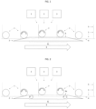
- the inspection device comprises a transport device 1, a rotation device 2, and a measuring device 3.
- the transport device 1 comprises transport planes 4 and feed planes 5.
- the inspection device contains two transport devices 1 comprising each a transport plane 4 on which one or more feed planes 5 are fixed.
- the rotation device 2 comprises two rotation planes 6/6a.
- the inspection device comprises two rotation devices 2.
- the rotation plane 6/6a can either be a static rotation plane 6 ( Figure 1 ) or comprise a moving rotation plane 6a, preferably moving in a reverse direction with regard to the transport device 1 (see Figure 2 ).
- the inspection device comprises one or more measuring devices 3, which can be positioned at any position in the inspection device. Thereby, the position of the measuring device 3 depends on the property that should be measured. If the inspection device comprises more than one measuring device 3, more than one property can be easily measured within one inspection device. Sometimes, it might be necessary to install more than one measuring device 3 of the same kind, to obtain an entire view on the cylindrical body 7.
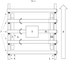
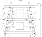
- two rotation planes 6/6a and/or transport planes 4 are parallel ( Figure 3 ). In another example, the distance between two rotation planes 6/6a and/or transport planes 4 changes, i.e. diminishes ( Figure 4 ) or extends. This might be beneficial, if a measuring device 3 needs to measure through the cylindrical body 7.
- more than one measuring device 3 of the same type can be installed at different positions to obtain an entire inspection of the whole cylindrical body 7 ( Figure 4 ).
- Another example (not shown), having the same effect, is an inspection device in which one rotation device 2 is arranged diagonal from a top view.
- the transport device 1 is configured to move a cylindrical body 7 relative to the measuring device 3.
- the cylindrical body/bodies 7 move(s) in a specific direction 8.
- the cylindrical body 7 arrives at the inspection device, the cylindrical body 7 is at least in contact with the transport plane 4, and usually in contact with the transport plane 4 and the feed plane 5.
- the cylindrical body 7 gets in contact with the rotation plane 6/6a, while it moves further relative to the measuring device 3.
- the cylindrical body 7 Since the speed of the rotation plane 6/6a compared to the feed plane 5 is different, the cylindrical body 7 starts to rotate around its rotation axis. While the cylindrical body 7 is moving relative to the measuring device 3 and while the cylindrical body 7 is rotating, one or more measuring devices 3 measures one or more properties. By the rotation of the cylindrical body 7 and a specific position and focus of the measuring device 3, the entire circumference of the cylindrical body 7 can be measured.
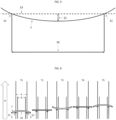
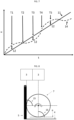
- the way of measurement of the curvature is described based on Figures 5 to 8 . Based on Figure 5 , the definition of the curvature of the cylindrical body 7 will be explained.
- the cylindrical portion of the cylindrical body 7 is in contact with two defined contact points 11 having a distance of 1000 mm.
- the curvature herein is the maximum length of the deviation of the outer surface at any position of the cylindrical body 12 from an ideal line 13 defined by the two contact points 11 measured when the cylindrical body 7 is rotated 360 degrees around its rotation axis. If the cylindrical portion of the cylindrical body is longer than 1000 mm, the measurement is conducted in a way that the middle of the cylindrical portion of the cylindrical body is in the middle of the two contact points.
- FIG. 6 An exemplary measurement of a cylindrical body 7 having a curvature is depicted in Figures 6 and 7 .
- the cylindrical body 7 is in contact with the feed planes 5 defining the two contact points 11 and the rotation planes 6/6a so that the cylindrical body 7 is rotating while the feed planes 5 are moving in a direction 8.
- the measurement is conducted along the viewline.
- the measuring device 3 (not shown) measures the positions x of the contact points 11 and a position at the outer surface of the cylindrical body 7 between the contact points 11 over the time t.
- the position 14 at the outer surface of the cylindrical body 7 between the contact points 11 is in front of the positions of the contact points 11 having always the same value and thus the position 14 has a higher value x.
- the length between the two points 11 and 14 is the length of the deviation of the outer surface of the cylindrical body 12.
- the curvature protrudes in the paper plane and the position at the outer surface of the cylindrical body 7 between the contact points 11 and the positions of the contact points 11 have the same value x.
- the position at the outer surface of the cylindrical body 7 between the contact points 11 is behind the positions of the contact points 11 and thus the position 14 has a lower value x.
- the length between the two contact points 11 and 14 is the length of the deviation of the outer surface of the cylindrical body 12.
- the bending protrudes out of the paper plane and the position at the outer surface of the cylindrical body 7 between the contact points 11 and the positions of the contact points 11 have the same level.
- the cylindrical body 7 rotated 360° and the measuring results are the same as for T1.
- the curvature is the longest distance evaluated by the above described method at any position of the cylindrical body between the two contact points 11. To obtain the curvature, i.e. the maximum length of the deviation of the outer surface at any position of the cylindrical body 12 from an ideal line 13, every point of the outer surface must be measured in the above-described way. All points are measured sequentially or simultaneously.
- FIG 8 a schematic drawing of the angle between the normal of the feed plane 5 and measuring direction 15 is depicted. In addition, the angle of the rotation plane 6/6a and the measuring direction 16 is depicted. Both angles are 90°.
- curvature is measured as described in the following:
Landscapes
- Physics & Mathematics (AREA)
- General Physics & Mathematics (AREA)
- Health & Medical Sciences (AREA)
- Life Sciences & Earth Sciences (AREA)
- Chemical & Material Sciences (AREA)
- Analytical Chemistry (AREA)
- Biochemistry (AREA)
- General Health & Medical Sciences (AREA)
- Immunology (AREA)
- Pathology (AREA)
- Engineering & Computer Science (AREA)
- Textile Engineering (AREA)
- Length Measuring Devices With Unspecified Measuring Means (AREA)
- Investigating Materials By The Use Of Optical Means Adapted For Particular Applications (AREA)
- A Measuring Device Byusing Mechanical Method (AREA)
Claims (12)
- Eine Prüfvorrichtung für einen zylindrischen Körper (7), umfassend:i) eine Transportvorrichtung (1),ii) eine Rotationsvorrichtung (2), undiii) eine Messvorrichtung (3);wobei die Transportvorrichtung (1) so konfiguriert ist, dass sie einen zylindrischen Körper (7) relativ zu der Messvorrichtung (3) bewegt;wobei die Drehvorrichtung (2) und die Transportvorrichtung (1) so konfiguriert sind, dass sie den zylindrischen Körper (7) drehen, während sich der zylindrische Körper (7) relativ zu der Messvorrichtung (3) bewegt;wobei die Messvorrichtung (3) so konfiguriert ist, dass sie den zylindrischen Körper (7) misst, während sich der zylindrische Körper (7) relativ zu der Messvorrichtung (3) bewegt und während sich der zylindrische Körper (7) dreht; undwobei die Transportvorrichtung (1) eine Transportebene (4) aufweist,wobei die Drehvorrichtung (2) eine Rotationsebene (6) umfasst,wobei die Transportvorrichtung (1) eine Zuführebene (5) aufweist,wobei mindestens ein Teil der Rotationsebene (6) parallel zur Transportebene (4) und mindestens ein Teil der Rotationsebene (6) senkrecht zur Zuführebene (5) verläuft,wobei die Transportvorrichtung (1) so gestaltet ist, dass während der Drehung des zylindrischen Körpers (7) der zylindrische Körper (7) nicht in Kontakt mit der Transportebene (4) der Transportvorrichtung (1) ist,wobei die Zuführebene (5) statisch auf der Transportebene (4) montiert ist,wobei der Winkel (15) zwischen der Normalen der Zuführebene (5) und der Mittellinie der Messvorrichtung (3) mehr als 45° bis weniger als 135°, vorzugsweise 60° bis 120°, mehr bevorzugt 70° bis 110°, mehr bevorzugt 80° bis 100°, mehr bevorzugt 85° bis 95°, am meisten bevorzugt 90° beträgt.
- Die Prüfvorrichtung für einen zylindrischen Körper (7) nach Anspruch 1,wobei die Transportebene (4) aus einem Polymer besteht; und/oderwobei die Zuführungsebene (5) aus Polymer, Graphit oder Holz besteht.
- Die Prüfvorrichtung für einen zylindrischen Körper (7) nach Anspruch 1 oder 2, wobei die Rotationsebene (6) aus einem Polymer besteht.
- Die Prüfvorrichtung für einen zylindrischen Körper (7) nach einem der vorhergehenden Ansprüche, wobei die Rotationsebene eine bewegliche Rotationsebene (6a) ist, wobei sich die bewegliche Rotationsebene (6a) relativ zur Messvorrichtung (3) und zur Transportvorrichtung (1) bewegt.
- Die Prüfvorrichtung für einen zylindrischen Körper (7) nach Anspruch 4, wobei die bewegliche Rotationsebene (6a) so konfiguriert ist, dass sie sich in umgekehrter Richtung in Bezug auf die Transportvorrichtung (1) bewegt, vorzugsweise mit einer Geschwindigkeit von 0,001 km/h bis 10 km/h.
- Die Prüfvorrichtung für einen zylindrischen Körper (7) nach einem der vorhergehenden Ansprüche, wobei die Rotationsebene (6) eben ist.
- Die Prüfvorrichtung für einen zylindrischen Körper (7) nach einem der vorhergehenden Ansprüche, wobei die Transportebene (4) und die Rotationsebene eben und parallel zueinander sind.
- Die Prüfvorrichtung für einen zylindrischen Körper (7) nach einem der vorhergehenden Ansprüche, wobei die Breite der Rotationsebene (6b) 0,1 mm bis 200 mm, vorzugsweise 1 mm bis 50 mm, besonders bevorzugt 1 mm bis 5 mm beträgt.
- Die Prüfvorrichtung für einen zylindrischen Körper (7) nach einem der vorhergehenden Ansprüche, wobei die Länge der Rotationsebene (6c) 1 bis 50 cm beträgt.
- Die Prüfeinrichtung für einen zylindrischen Körper (7) nach einem der vorhergehenden Ansprüche, wobei die Messeinrichtung (3) eine Objekt- und Geometrieprüfeinrichtung, vorzugsweise mit Lasertechnik oder Kamera, ist.
- Die Prüfvorrichtung für einen zylindrischen Körper (7) nach einem der vorhergehenden Ansprüche, wobei der Winkel zwischen der Rotationsebene und der Mittellinie der Messvorrichtung mehr als 45° bis weniger als 135°, vorzugsweise 60° bis 120°, mehr bevorzugt 70° bis 110°, mehr bevorzugt 80° bis 100°, mehr bevorzugt 85° bis 95°, am meisten bevorzugt 90° beträgt.
- Die Prüfvorrichtung nach einem der Ansprüche 1 bis 11, wobei der zylindrische Körper ein Rohr ist; und/oderwobei der zylindrische Körper aus einem Polymer oder Glas besteht, vorzugsweise aus zyklischem Olefin-Copolymer (COC), zyklischem Olefin-Polymer (COP), Aluminosilikatglas oder Borosilikatglas; und/oderwobei die Länge des zylindrischen Teils des zylindrischen Körpers 1 cm oder mehr bis 1000 cm oder weniger, vorzugsweise 20 cm oder mehr bis 400 cm oder weniger, noch bevorzugter 60 cm oder mehr bis 300 cm oder weniger, noch bevorzugter 100 cm oder mehr bis 200 cm oder weniger, am meisten bevorzugt 120 cm oder mehr bis 180 cm oder weniger beträgt; und/oderder Außendurchmesser des zylindrischen Teils des zylindrischen Körpers 2 mm oder mehr und 100 mm oder weniger, vorzugsweise 4 mm oder mehr und 50 mm oder weniger, vorzugsweise 6 mm oder mehr und 35 mm oder weniger, vorzugsweise 8 mm oder mehr und 25 mm oder weniger, besonders bevorzugt 10 mm oder mehr und 20 mm oder weniger beträgt.
Priority Applications (6)
| Application Number | Priority Date | Filing Date | Title |
|---|---|---|---|
| EP20150706.8A EP3848701B1 (de) | 2020-01-08 | 2020-01-08 | Inspektionsvorrichtung für zylindrische körper |
| MYPI2020005960A MY210140A (en) | 2020-01-08 | 2020-11-12 | Inspection device for cylindrical bodies |
| CN202011499567.XA CN113091604B (zh) | 2020-01-08 | 2020-12-17 | 用于圆柱形主体的检测设备和集束包 |
| CN202122453257.0U CN216482803U (zh) | 2020-01-08 | 2020-12-17 | 用于圆柱形主体的检测设备和集束包 |
| JP2021001455A JP7796479B2 (ja) | 2020-01-08 | 2021-01-07 | 円筒体用の検査装置 |
| US17/145,040 US12181270B2 (en) | 2020-01-08 | 2021-01-08 | Inspection device for cylindrical bodies |
Applications Claiming Priority (1)
| Application Number | Priority Date | Filing Date | Title |
|---|---|---|---|
| EP20150706.8A EP3848701B1 (de) | 2020-01-08 | 2020-01-08 | Inspektionsvorrichtung für zylindrische körper |
Publications (2)
| Publication Number | Publication Date |
|---|---|
| EP3848701A1 EP3848701A1 (de) | 2021-07-14 |
| EP3848701B1 true EP3848701B1 (de) | 2024-10-09 |
Family
ID=69156190
Family Applications (1)
| Application Number | Title | Priority Date | Filing Date |
|---|---|---|---|
| EP20150706.8A Active EP3848701B1 (de) | 2020-01-08 | 2020-01-08 | Inspektionsvorrichtung für zylindrische körper |
Country Status (5)
| Country | Link |
|---|---|
| US (1) | US12181270B2 (de) |
| EP (1) | EP3848701B1 (de) |
| JP (1) | JP7796479B2 (de) |
| CN (2) | CN113091604B (de) |
| MY (1) | MY210140A (de) |
Cited By (1)
| Publication number | Priority date | Publication date | Assignee | Title |
|---|---|---|---|---|
| JP7796479B2 (ja) | 2020-01-08 | 2026-01-09 | ショット アクチエンゲゼルシャフト | 円筒体用の検査装置 |
Families Citing this family (2)
| Publication number | Priority date | Publication date | Assignee | Title |
|---|---|---|---|---|
| EP4145086B1 (de) | 2021-09-07 | 2025-12-17 | Schott Ag | Vorrichtung zur inspektion eines kreisförmigen länglichen elements |
| EP4151605A1 (de) | 2021-09-20 | 2023-03-22 | Schott Ag | Verfahren und system zur herstellung von geschnittenen länglichen elementen |
Citations (1)
| Publication number | Priority date | Publication date | Assignee | Title |
|---|---|---|---|---|
| JPS60209151A (ja) * | 1984-03-31 | 1985-10-21 | Nuclear Fuel Ind Ltd | 核燃料ペレツト等円柱状体の周側面欠陥部自動検査装置 |
Family Cites Families (22)
| Publication number | Priority date | Publication date | Assignee | Title |
|---|---|---|---|---|
| US4226539A (en) * | 1976-12-24 | 1980-10-07 | Hitachi, Ltd. | Cylindrical body appearance inspection apparatus |
| US4483615A (en) * | 1981-12-18 | 1984-11-20 | Owens-Illinois, Inc. | Method and apparatus for detecting checks in glass tubes |
| JPS61292011A (ja) * | 1985-05-20 | 1986-12-22 | Fujitsu Ltd | 加工品の良否選別装置 |
| JPH01145555A (ja) * | 1987-12-01 | 1989-06-07 | Nippon Taisanbin Kogyo Kk | 光学的検査装置 |
| DE4022733C1 (en) * | 1989-12-19 | 1991-05-08 | Elpatronic Ag, Zug, Ch | Three=dimensional cavity inspection appts. - uses matrix or line camera to receive reflected light via gp. of four mirrors and deflecting mirror |
| JPH0772087A (ja) * | 1993-09-03 | 1995-03-17 | Mitsubishi Materials Corp | 円筒物の外面検査装置 |
| JPH07218442A (ja) * | 1994-02-02 | 1995-08-18 | Canon Inc | 円筒物検査装置 |
| JP3333048B2 (ja) * | 1994-06-28 | 2002-10-07 | 三菱原子燃料株式会社 | 円柱体の検査装置 |
| DE29600902U1 (de) * | 1996-01-19 | 1997-05-15 | Heuft Systemtechnik Gmbh, 56659 Burgbrohl | Vorrichtung zur Inspektion von Gegenständen, insbesondere Getränkeflaschen |
| JPH1145555A (ja) | 1997-07-30 | 1999-02-16 | Sony Corp | 編集方法及び装置 |
| DE19916703A1 (de) * | 1999-04-14 | 2000-10-19 | Haering Franz | Inspektionsmaschine für transparente Behälter |
| JP3756798B2 (ja) * | 2001-02-22 | 2006-03-15 | 新日本製鐵株式会社 | 金属管の加工性評価装置及び評価方法 |
| DE10303659B4 (de) * | 2003-01-23 | 2005-07-28 | Berliner Elektronenspeicherring-Gesellschaft für Synchrotronstrahlung mbH | Optisches Messverfahren zur Ermittlung von Idealformabweichungen technisch polierter Oberflächen und Präzisionsmessmaschine zur Durchführung des Messverfahrens |
| WO2005031328A1 (ja) | 2003-09-30 | 2005-04-07 | Eisai Co., Ltd. | 検査システム |
| EP1698951A1 (de) * | 2005-03-01 | 2006-09-06 | Aktiebolaget SKF | Vorrichtung und Verfahren zum Angeben einer Kreisbahn und/oder einer Abweichung einer im wesentlichen runden Oberfläche |
| JP2007047097A (ja) * | 2005-08-12 | 2007-02-22 | Sanyo Special Steel Co Ltd | リング状素材の円筒度及び真円度の自動検査装置 |
| JP5166897B2 (ja) * | 2008-02-01 | 2013-03-21 | 大王製紙株式会社 | シートロールの検査装置及び検査方法 |
| DE102009035585A1 (de) | 2009-07-31 | 2011-02-03 | Krones Ag | Inspektionsvorrichtung und Inspektionsverfahren zum Erkennen von Fremdkörpern in einem gefüllten Behälter |
| EP3709007B1 (de) * | 2010-10-08 | 2022-03-30 | Capsugel Belgium NV | Vorrichtung und verfahren zur erfassung eines zweidimensionalen bildes der oberfläche eines dreidimensionalen objekts |
| DE102012109189B3 (de) * | 2012-09-27 | 2014-03-27 | Schott Ag | Verfahren und Vorrichtung zum wärmeweichen Verschließen von Glasrohren |
| CN106093060A (zh) * | 2016-08-25 | 2016-11-09 | 成都贝森伟任科技有限责任公司 | 一种圆柱体制品外观检测系统 |
| EP3848701B1 (de) | 2020-01-08 | 2024-10-09 | Schott Ag | Inspektionsvorrichtung für zylindrische körper |
-
2020
- 2020-01-08 EP EP20150706.8A patent/EP3848701B1/de active Active
- 2020-11-12 MY MYPI2020005960A patent/MY210140A/en unknown
- 2020-12-17 CN CN202011499567.XA patent/CN113091604B/zh active Active
- 2020-12-17 CN CN202122453257.0U patent/CN216482803U/zh active Active
-
2021
- 2021-01-07 JP JP2021001455A patent/JP7796479B2/ja active Active
- 2021-01-08 US US17/145,040 patent/US12181270B2/en active Active
Patent Citations (1)
| Publication number | Priority date | Publication date | Assignee | Title |
|---|---|---|---|---|
| JPS60209151A (ja) * | 1984-03-31 | 1985-10-21 | Nuclear Fuel Ind Ltd | 核燃料ペレツト等円柱状体の周側面欠陥部自動検査装置 |
Cited By (1)
| Publication number | Priority date | Publication date | Assignee | Title |
|---|---|---|---|---|
| JP7796479B2 (ja) | 2020-01-08 | 2026-01-09 | ショット アクチエンゲゼルシャフト | 円筒体用の検査装置 |
Also Published As
| Publication number | Publication date |
|---|---|
| JP2021110751A (ja) | 2021-08-02 |
| CN216482803U (zh) | 2022-05-10 |
| US12181270B2 (en) | 2024-12-31 |
| CN113091604B (zh) | 2025-05-27 |
| CN113091604A (zh) | 2021-07-09 |
| JP7796479B2 (ja) | 2026-01-09 |
| MY210140A (en) | 2025-08-28 |
| EP3848701A1 (de) | 2021-07-14 |
| US20210207953A1 (en) | 2021-07-08 |
Similar Documents
| Publication | Publication Date | Title |
|---|---|---|
| US12181270B2 (en) | Inspection device for cylindrical bodies | |
| CA1202704A (en) | Down and stuck bottle inspection system | |
| EP0124164B1 (de) | Apparat zum Überprüfen von Behältern | |
| JP6255479B2 (ja) | タバコ産業で使用される機械の中を転送されるマルチセグメントロッド内の回転したセグメントの検出方法及び装置 | |
| EP3797883B1 (de) | Vorrichtung zur inspektion eines pharmazeutischen behälters | |
| EP0320139A2 (de) | Optische Dickenmessung der Wand eines transparenten Behälters | |
| EP3363767A1 (de) | Maschine und verfahren zur messung von abmessungsparametern von korkstopfen | |
| WO2019108936A1 (en) | Tubing dimensional measurement system | |
| EP3311148A1 (de) | Zerstörungsfreie röntgeninspektionsmaschine, vorrichtungen für derartige maschine und verfahren zum betrieb derselben | |
| US11921128B2 (en) | Apparatus for inspecting pharmaceutical containers | |
| US9622510B2 (en) | Transfer disc and its use | |
| JP5076247B2 (ja) | 非円形の透明容器の側壁の厚みを測定する装置及び方法 | |
| US5701178A (en) | Non-damaging flatness and thickness gauge for glass | |
| US3436555A (en) | Ovality measurement apparatus comprising two photoelectric gauging systems having an angle between their optical axes of the order of 70 | |
| US5872715A (en) | Automatic inspection and certification system | |
| EP1955055B1 (de) | Vorrichtung und verfahren zur sicherstellung der rotation eines behälters während einer inspektion | |
| US12560421B2 (en) | Apparatus for the inspection of a circular elongated element | |
| CN111924455B (zh) | 一种浮动机构、料盘浮动检查设备及料盘传送系统 | |
| JP2013092439A (ja) | 管の内面曲がり測定装置およびそれを用いた測定方法 | |
| US12441650B2 (en) | Method and system for obtaining cut elongated elements | |
| CN112295938A (zh) | 一种基于双远心镜头检测尺寸视觉设备及其使用方法 | |
| KR102888428B1 (ko) | 탭 샤프트의 외경 자동검사장치 | |
| JP5442933B2 (ja) | ペーパーロールの搬送方法及びペーパーロールの検査設備 | |
| CN106553781A (zh) | 药瓶用在线称重装置及称重方法 | |
| KR101327276B1 (ko) | 편평광을 이용한 비전검사 장치 |
Legal Events
| Date | Code | Title | Description |
|---|---|---|---|
| STAA | Information on the status of an ep patent application or granted ep patent |
Free format text: STATUS: EXAMINATION IS IN PROGRESS |
|
| PUAI | Public reference made under article 153(3) epc to a published international application that has entered the european phase |
Free format text: ORIGINAL CODE: 0009012 |
|
| 17P | Request for examination filed |
Effective date: 20200108 |
|
| AK | Designated contracting states |
Kind code of ref document: A1 Designated state(s): AL AT BE BG CH CY CZ DE DK EE ES FI FR GB GR HR HU IE IS IT LI LT LU LV MC MK MT NL NO PL PT RO RS SE SI SK SM TR |
|
| P01 | Opt-out of the competence of the unified patent court (upc) registered |
Effective date: 20230512 |
|
| GRAJ | Information related to disapproval of communication of intention to grant by the applicant or resumption of examination proceedings by the epo deleted |
Free format text: ORIGINAL CODE: EPIDOSDIGR1 |
|
| STAA | Information on the status of an ep patent application or granted ep patent |
Free format text: STATUS: GRANT OF PATENT IS INTENDED |
|
| GRAP | Despatch of communication of intention to grant a patent |
Free format text: ORIGINAL CODE: EPIDOSNIGR1 |
|
| INTG | Intention to grant announced |
Effective date: 20240514 |
|
| RIN1 | Information on inventor provided before grant (corrected) |
Inventor name: WITKOWSKI, ROBERT Inventor name: EISNER, ARMIN Inventor name: WITZMANN, ANDRE |
|
| GRAJ | Information related to disapproval of communication of intention to grant by the applicant or resumption of examination proceedings by the epo deleted |
Free format text: ORIGINAL CODE: EPIDOSDIGR1 |
|
| STAA | Information on the status of an ep patent application or granted ep patent |
Free format text: STATUS: EXAMINATION IS IN PROGRESS |
|
| INTC | Intention to grant announced (deleted) | ||
| GRAP | Despatch of communication of intention to grant a patent |
Free format text: ORIGINAL CODE: EPIDOSNIGR1 |
|
| STAA | Information on the status of an ep patent application or granted ep patent |
Free format text: STATUS: GRANT OF PATENT IS INTENDED |
|
| GRAS | Grant fee paid |
Free format text: ORIGINAL CODE: EPIDOSNIGR3 |
|
| GRAA | (expected) grant |
Free format text: ORIGINAL CODE: 0009210 |
|
| STAA | Information on the status of an ep patent application or granted ep patent |
Free format text: STATUS: THE PATENT HAS BEEN GRANTED |
|
| INTG | Intention to grant announced |
Effective date: 20240827 |
|
| AK | Designated contracting states |
Kind code of ref document: B1 Designated state(s): AL AT BE BG CH CY CZ DE DK EE ES FI FR GB GR HR HU IE IS IT LI LT LU LV MC MK MT NL NO PL PT RO RS SE SI SK SM TR |
|
| REG | Reference to a national code |
Ref country code: CH Ref legal event code: EP |
|
| REG | Reference to a national code |
Ref country code: DE Ref legal event code: R096 Ref document number: 602020038879 Country of ref document: DE |
|
| REG | Reference to a national code |
Ref country code: IE Ref legal event code: FG4D |
|
| REG | Reference to a national code |
Ref country code: LT Ref legal event code: MG9D |
|
| REG | Reference to a national code |
Ref country code: NL Ref legal event code: MP Effective date: 20241009 |
|
| REG | Reference to a national code |
Ref country code: AT Ref legal event code: MK05 Ref document number: 1731074 Country of ref document: AT Kind code of ref document: T Effective date: 20241009 |
|
| PG25 | Lapsed in a contracting state [announced via postgrant information from national office to epo] |
Ref country code: NL Free format text: LAPSE BECAUSE OF FAILURE TO SUBMIT A TRANSLATION OF THE DESCRIPTION OR TO PAY THE FEE WITHIN THE PRESCRIBED TIME-LIMIT Effective date: 20241009 |
|
| PG25 | Lapsed in a contracting state [announced via postgrant information from national office to epo] |
Ref country code: NL Free format text: LAPSE BECAUSE OF FAILURE TO SUBMIT A TRANSLATION OF THE DESCRIPTION OR TO PAY THE FEE WITHIN THE PRESCRIBED TIME-LIMIT Effective date: 20241009 |
|
| PG25 | Lapsed in a contracting state [announced via postgrant information from national office to epo] |
Ref country code: IS Free format text: LAPSE BECAUSE OF FAILURE TO SUBMIT A TRANSLATION OF THE DESCRIPTION OR TO PAY THE FEE WITHIN THE PRESCRIBED TIME-LIMIT Effective date: 20250209 Ref country code: PT Free format text: LAPSE BECAUSE OF FAILURE TO SUBMIT A TRANSLATION OF THE DESCRIPTION OR TO PAY THE FEE WITHIN THE PRESCRIBED TIME-LIMIT Effective date: 20250210 Ref country code: HR Free format text: LAPSE BECAUSE OF FAILURE TO SUBMIT A TRANSLATION OF THE DESCRIPTION OR TO PAY THE FEE WITHIN THE PRESCRIBED TIME-LIMIT Effective date: 20241009 |
|
| PGFP | Annual fee paid to national office [announced via postgrant information from national office to epo] |
Ref country code: DE Payment date: 20250121 Year of fee payment: 6 |
|
| PG25 | Lapsed in a contracting state [announced via postgrant information from national office to epo] |
Ref country code: FI Free format text: LAPSE BECAUSE OF FAILURE TO SUBMIT A TRANSLATION OF THE DESCRIPTION OR TO PAY THE FEE WITHIN THE PRESCRIBED TIME-LIMIT Effective date: 20241009 |
|
| PG25 | Lapsed in a contracting state [announced via postgrant information from national office to epo] |
Ref country code: BG Free format text: LAPSE BECAUSE OF FAILURE TO SUBMIT A TRANSLATION OF THE DESCRIPTION OR TO PAY THE FEE WITHIN THE PRESCRIBED TIME-LIMIT Effective date: 20241009 |
|
| PG25 | Lapsed in a contracting state [announced via postgrant information from national office to epo] |
Ref country code: ES Free format text: LAPSE BECAUSE OF FAILURE TO SUBMIT A TRANSLATION OF THE DESCRIPTION OR TO PAY THE FEE WITHIN THE PRESCRIBED TIME-LIMIT Effective date: 20241009 |
|
| PG25 | Lapsed in a contracting state [announced via postgrant information from national office to epo] |
Ref country code: NO Free format text: LAPSE BECAUSE OF FAILURE TO SUBMIT A TRANSLATION OF THE DESCRIPTION OR TO PAY THE FEE WITHIN THE PRESCRIBED TIME-LIMIT Effective date: 20250109 |
|
| PG25 | Lapsed in a contracting state [announced via postgrant information from national office to epo] |
Ref country code: LV Free format text: LAPSE BECAUSE OF FAILURE TO SUBMIT A TRANSLATION OF THE DESCRIPTION OR TO PAY THE FEE WITHIN THE PRESCRIBED TIME-LIMIT Effective date: 20241009 Ref country code: GR Free format text: LAPSE BECAUSE OF FAILURE TO SUBMIT A TRANSLATION OF THE DESCRIPTION OR TO PAY THE FEE WITHIN THE PRESCRIBED TIME-LIMIT Effective date: 20250110 Ref country code: AT Free format text: LAPSE BECAUSE OF FAILURE TO SUBMIT A TRANSLATION OF THE DESCRIPTION OR TO PAY THE FEE WITHIN THE PRESCRIBED TIME-LIMIT Effective date: 20241009 |
|
| PG25 | Lapsed in a contracting state [announced via postgrant information from national office to epo] |
Ref country code: PL Free format text: LAPSE BECAUSE OF FAILURE TO SUBMIT A TRANSLATION OF THE DESCRIPTION OR TO PAY THE FEE WITHIN THE PRESCRIBED TIME-LIMIT Effective date: 20241009 |
|
| PGFP | Annual fee paid to national office [announced via postgrant information from national office to epo] |
Ref country code: FR Payment date: 20250127 Year of fee payment: 6 |
|
| PGFP | Annual fee paid to national office [announced via postgrant information from national office to epo] |
Ref country code: IT Payment date: 20250130 Year of fee payment: 6 |
|
| PG25 | Lapsed in a contracting state [announced via postgrant information from national office to epo] |
Ref country code: RS Free format text: LAPSE BECAUSE OF FAILURE TO SUBMIT A TRANSLATION OF THE DESCRIPTION OR TO PAY THE FEE WITHIN THE PRESCRIBED TIME-LIMIT Effective date: 20250109 |
|
| PG25 | Lapsed in a contracting state [announced via postgrant information from national office to epo] |
Ref country code: SM Free format text: LAPSE BECAUSE OF FAILURE TO SUBMIT A TRANSLATION OF THE DESCRIPTION OR TO PAY THE FEE WITHIN THE PRESCRIBED TIME-LIMIT Effective date: 20241009 |
|
| PG25 | Lapsed in a contracting state [announced via postgrant information from national office to epo] |
Ref country code: DK Free format text: LAPSE BECAUSE OF FAILURE TO SUBMIT A TRANSLATION OF THE DESCRIPTION OR TO PAY THE FEE WITHIN THE PRESCRIBED TIME-LIMIT Effective date: 20241009 |
|
| REG | Reference to a national code |
Ref country code: DE Ref legal event code: R097 Ref document number: 602020038879 Country of ref document: DE |
|
| PG25 | Lapsed in a contracting state [announced via postgrant information from national office to epo] |
Ref country code: EE Free format text: LAPSE BECAUSE OF FAILURE TO SUBMIT A TRANSLATION OF THE DESCRIPTION OR TO PAY THE FEE WITHIN THE PRESCRIBED TIME-LIMIT Effective date: 20241009 |
|
| PG25 | Lapsed in a contracting state [announced via postgrant information from national office to epo] |
Ref country code: RO Free format text: LAPSE BECAUSE OF FAILURE TO SUBMIT A TRANSLATION OF THE DESCRIPTION OR TO PAY THE FEE WITHIN THE PRESCRIBED TIME-LIMIT Effective date: 20241009 |
|
| PG25 | Lapsed in a contracting state [announced via postgrant information from national office to epo] |
Ref country code: SK Free format text: LAPSE BECAUSE OF FAILURE TO SUBMIT A TRANSLATION OF THE DESCRIPTION OR TO PAY THE FEE WITHIN THE PRESCRIBED TIME-LIMIT Effective date: 20241009 |
|
| PG25 | Lapsed in a contracting state [announced via postgrant information from national office to epo] |
Ref country code: CZ Free format text: LAPSE BECAUSE OF FAILURE TO SUBMIT A TRANSLATION OF THE DESCRIPTION OR TO PAY THE FEE WITHIN THE PRESCRIBED TIME-LIMIT Effective date: 20241009 |
|
| PLBE | No opposition filed within time limit |
Free format text: ORIGINAL CODE: 0009261 |
|
| STAA | Information on the status of an ep patent application or granted ep patent |
Free format text: STATUS: NO OPPOSITION FILED WITHIN TIME LIMIT |
|
| REG | Reference to a national code |
Ref country code: CH Ref legal event code: PL |
|
| PG25 | Lapsed in a contracting state [announced via postgrant information from national office to epo] |
Ref country code: SE Free format text: LAPSE BECAUSE OF FAILURE TO SUBMIT A TRANSLATION OF THE DESCRIPTION OR TO PAY THE FEE WITHIN THE PRESCRIBED TIME-LIMIT Effective date: 20241009 |
|
| PG25 | Lapsed in a contracting state [announced via postgrant information from national office to epo] |
Ref country code: LU Free format text: LAPSE BECAUSE OF NON-PAYMENT OF DUE FEES Effective date: 20250108 Ref country code: MC Free format text: LAPSE BECAUSE OF FAILURE TO SUBMIT A TRANSLATION OF THE DESCRIPTION OR TO PAY THE FEE WITHIN THE PRESCRIBED TIME-LIMIT Effective date: 20241009 |
|
| 26N | No opposition filed |
Effective date: 20250710 |
|
| GBPC | Gb: european patent ceased through non-payment of renewal fee |
Effective date: 20250109 |
|
| PG25 | Lapsed in a contracting state [announced via postgrant information from national office to epo] |
Ref country code: GB Free format text: LAPSE BECAUSE OF NON-PAYMENT OF DUE FEES Effective date: 20250109 Ref country code: BE Free format text: LAPSE BECAUSE OF NON-PAYMENT OF DUE FEES Effective date: 20250131 |
|
| PG25 | Lapsed in a contracting state [announced via postgrant information from national office to epo] |
Ref country code: CH Free format text: LAPSE BECAUSE OF NON-PAYMENT OF DUE FEES Effective date: 20250131 |
|
| REG | Reference to a national code |
Ref country code: BE Ref legal event code: MM Effective date: 20250131 |
|
| PG25 | Lapsed in a contracting state [announced via postgrant information from national office to epo] |
Ref country code: IE Free format text: LAPSE BECAUSE OF NON-PAYMENT OF DUE FEES Effective date: 20250108 |