EP3794244B1 - Doppelkupplungseinheit und antriebsanordnung mit einer solchen doppelkupplungseinheit - Google Patents
Doppelkupplungseinheit und antriebsanordnung mit einer solchen doppelkupplungseinheit Download PDFInfo
- Publication number
- EP3794244B1 EP3794244B1 EP19726358.5A EP19726358A EP3794244B1 EP 3794244 B1 EP3794244 B1 EP 3794244B1 EP 19726358 A EP19726358 A EP 19726358A EP 3794244 B1 EP3794244 B1 EP 3794244B1
- Authority
- EP
- European Patent Office
- Prior art keywords
- disk carrier
- clutch unit
- inner disk
- dual clutch
- channel
- Prior art date
- Legal status (The legal status is an assumption and is not a legal conclusion. Google has not performed a legal analysis and makes no representation as to the accuracy of the status listed.)
- Active
Links
Images


Classifications
-
- F—MECHANICAL ENGINEERING; LIGHTING; HEATING; WEAPONS; BLASTING
- F16—ENGINEERING ELEMENTS AND UNITS; GENERAL MEASURES FOR PRODUCING AND MAINTAINING EFFECTIVE FUNCTIONING OF MACHINES OR INSTALLATIONS; THERMAL INSULATION IN GENERAL
- F16D—COUPLINGS FOR TRANSMITTING ROTATION; CLUTCHES; BRAKES
- F16D13/00—Friction clutches
- F16D13/58—Details
- F16D13/72—Features relating to cooling
-
- F—MECHANICAL ENGINEERING; LIGHTING; HEATING; WEAPONS; BLASTING
- F16—ENGINEERING ELEMENTS AND UNITS; GENERAL MEASURES FOR PRODUCING AND MAINTAINING EFFECTIVE FUNCTIONING OF MACHINES OR INSTALLATIONS; THERMAL INSULATION IN GENERAL
- F16D—COUPLINGS FOR TRANSMITTING ROTATION; CLUTCHES; BRAKES
- F16D25/00—Fluid-actuated clutches
- F16D25/12—Details not specific to one of the before-mentioned types
- F16D25/123—Details not specific to one of the before-mentioned types in view of cooling and lubrication
-
- B—PERFORMING OPERATIONS; TRANSPORTING
- B60—VEHICLES IN GENERAL
- B60K—ARRANGEMENT OR MOUNTING OF PROPULSION UNITS OR OF TRANSMISSIONS IN VEHICLES; ARRANGEMENT OR MOUNTING OF PLURAL DIVERSE PRIME-MOVERS IN VEHICLES; AUXILIARY DRIVES FOR VEHICLES; INSTRUMENTATION OR DASHBOARDS FOR VEHICLES; ARRANGEMENTS IN CONNECTION WITH COOLING, AIR INTAKE, GAS EXHAUST OR FUEL SUPPLY OF PROPULSION UNITS IN VEHICLES
- B60K17/00—Arrangement or mounting of transmissions in vehicles
- B60K17/04—Arrangement or mounting of transmissions in vehicles characterised by arrangement, location or kind of gearing
- B60K17/16—Arrangement or mounting of transmissions in vehicles characterised by arrangement, location or kind of gearing of differential gearing
- B60K17/165—Arrangement or mounting of transmissions in vehicles characterised by arrangement, location or kind of gearing of differential gearing provided between independent half axles
-
- F—MECHANICAL ENGINEERING; LIGHTING; HEATING; WEAPONS; BLASTING
- F16—ENGINEERING ELEMENTS AND UNITS; GENERAL MEASURES FOR PRODUCING AND MAINTAINING EFFECTIVE FUNCTIONING OF MACHINES OR INSTALLATIONS; THERMAL INSULATION IN GENERAL
- F16D—COUPLINGS FOR TRANSMITTING ROTATION; CLUTCHES; BRAKES
- F16D13/00—Friction clutches
- F16D13/22—Friction clutches with axially-movable clutching members
- F16D13/38—Friction clutches with axially-movable clutching members with flat clutching surfaces, e.g. discs
- F16D13/385—Friction clutches with axially-movable clutching members with flat clutching surfaces, e.g. discs double clutches, i.e. comprising two friction disc mounted on one driven shaft
-
- F—MECHANICAL ENGINEERING; LIGHTING; HEATING; WEAPONS; BLASTING
- F16—ENGINEERING ELEMENTS AND UNITS; GENERAL MEASURES FOR PRODUCING AND MAINTAINING EFFECTIVE FUNCTIONING OF MACHINES OR INSTALLATIONS; THERMAL INSULATION IN GENERAL
- F16D—COUPLINGS FOR TRANSMITTING ROTATION; CLUTCHES; BRAKES
- F16D13/00—Friction clutches
- F16D13/22—Friction clutches with axially-movable clutching members
- F16D13/38—Friction clutches with axially-movable clutching members with flat clutching surfaces, e.g. discs
- F16D13/52—Clutches with multiple lamellae ; Clutches in which three or more axially moveable members are fixed alternately to the shafts to be coupled and are pressed from one side towards an axially-located member
-
- F—MECHANICAL ENGINEERING; LIGHTING; HEATING; WEAPONS; BLASTING
- F16—ENGINEERING ELEMENTS AND UNITS; GENERAL MEASURES FOR PRODUCING AND MAINTAINING EFFECTIVE FUNCTIONING OF MACHINES OR INSTALLATIONS; THERMAL INSULATION IN GENERAL
- F16D—COUPLINGS FOR TRANSMITTING ROTATION; CLUTCHES; BRAKES
- F16D13/00—Friction clutches
- F16D13/58—Details
- F16D13/74—Features relating to lubrication
-
- F—MECHANICAL ENGINEERING; LIGHTING; HEATING; WEAPONS; BLASTING
- F16—ENGINEERING ELEMENTS AND UNITS; GENERAL MEASURES FOR PRODUCING AND MAINTAINING EFFECTIVE FUNCTIONING OF MACHINES OR INSTALLATIONS; THERMAL INSULATION IN GENERAL
- F16D—COUPLINGS FOR TRANSMITTING ROTATION; CLUTCHES; BRAKES
- F16D21/00—Systems comprising a plurality of actuated clutches
- F16D21/02—Systems comprising a plurality of actuated clutches for interconnecting three or more shafts or other transmission members in different ways
-
- F—MECHANICAL ENGINEERING; LIGHTING; HEATING; WEAPONS; BLASTING
- F16—ENGINEERING ELEMENTS AND UNITS; GENERAL MEASURES FOR PRODUCING AND MAINTAINING EFFECTIVE FUNCTIONING OF MACHINES OR INSTALLATIONS; THERMAL INSULATION IN GENERAL
- F16D—COUPLINGS FOR TRANSMITTING ROTATION; CLUTCHES; BRAKES
- F16D25/00—Fluid-actuated clutches
- F16D25/08—Fluid-actuated clutches with fluid-actuated member not rotating with a clutching member
- F16D25/082—Fluid-actuated clutches with fluid-actuated member not rotating with a clutching member the line of action of the fluid-actuated members co-inciding with the axis of rotation
-
- F—MECHANICAL ENGINEERING; LIGHTING; HEATING; WEAPONS; BLASTING
- F16—ENGINEERING ELEMENTS AND UNITS; GENERAL MEASURES FOR PRODUCING AND MAINTAINING EFFECTIVE FUNCTIONING OF MACHINES OR INSTALLATIONS; THERMAL INSULATION IN GENERAL
- F16D—COUPLINGS FOR TRANSMITTING ROTATION; CLUTCHES; BRAKES
- F16D25/00—Fluid-actuated clutches
- F16D25/10—Clutch systems with a plurality of fluid-actuated clutches
-
- F—MECHANICAL ENGINEERING; LIGHTING; HEATING; WEAPONS; BLASTING
- F16—ENGINEERING ELEMENTS AND UNITS; GENERAL MEASURES FOR PRODUCING AND MAINTAINING EFFECTIVE FUNCTIONING OF MACHINES OR INSTALLATIONS; THERMAL INSULATION IN GENERAL
- F16H—GEARING
- F16H57/00—General details of gearing
- F16H57/04—Features relating to lubrication or cooling or heating
- F16H57/042—Guidance of lubricant
- F16H57/0427—Guidance of lubricant on rotary parts, e.g. using baffles for collecting lubricant by centrifugal force
- F16H57/0428—Grooves with pumping effect for supplying lubricants
-
- F—MECHANICAL ENGINEERING; LIGHTING; HEATING; WEAPONS; BLASTING
- F16—ENGINEERING ELEMENTS AND UNITS; GENERAL MEASURES FOR PRODUCING AND MAINTAINING EFFECTIVE FUNCTIONING OF MACHINES OR INSTALLATIONS; THERMAL INSULATION IN GENERAL
- F16H—GEARING
- F16H57/00—General details of gearing
- F16H57/04—Features relating to lubrication or cooling or heating
- F16H57/042—Guidance of lubricant
- F16H57/043—Guidance of lubricant within rotary parts, e.g. axial channels or radial openings in shafts
-
- F—MECHANICAL ENGINEERING; LIGHTING; HEATING; WEAPONS; BLASTING
- F16—ENGINEERING ELEMENTS AND UNITS; GENERAL MEASURES FOR PRODUCING AND MAINTAINING EFFECTIVE FUNCTIONING OF MACHINES OR INSTALLATIONS; THERMAL INSULATION IN GENERAL
- F16H—GEARING
- F16H57/00—General details of gearing
- F16H57/04—Features relating to lubrication or cooling or heating
- F16H57/0467—Elements of gearings to be lubricated, cooled or heated
- F16H57/0473—Friction devices, e.g. clutches or brakes
-
- F—MECHANICAL ENGINEERING; LIGHTING; HEATING; WEAPONS; BLASTING
- F16—ENGINEERING ELEMENTS AND UNITS; GENERAL MEASURES FOR PRODUCING AND MAINTAINING EFFECTIVE FUNCTIONING OF MACHINES OR INSTALLATIONS; THERMAL INSULATION IN GENERAL
- F16H—GEARING
- F16H57/00—General details of gearing
- F16H57/04—Features relating to lubrication or cooling or heating
- F16H57/048—Type of gearings to be lubricated, cooled or heated
- F16H57/0482—Gearings with gears having orbital motion
- F16H57/0483—Axle or inter-axle differentials
-
- F—MECHANICAL ENGINEERING; LIGHTING; HEATING; WEAPONS; BLASTING
- F16—ENGINEERING ELEMENTS AND UNITS; GENERAL MEASURES FOR PRODUCING AND MAINTAINING EFFECTIVE FUNCTIONING OF MACHINES OR INSTALLATIONS; THERMAL INSULATION IN GENERAL
- F16D—COUPLINGS FOR TRANSMITTING ROTATION; CLUTCHES; BRAKES
- F16D21/00—Systems comprising a plurality of actuated clutches
- F16D21/02—Systems comprising a plurality of actuated clutches for interconnecting three or more shafts or other transmission members in different ways
- F16D21/06—Systems comprising a plurality of actuated clutches for interconnecting three or more shafts or other transmission members in different ways at least two driving shafts or two driven shafts being concentric
- F16D2021/0607—Double clutch with torque input plate in-between the two clutches, i.e. having a central input plate
-
- F—MECHANICAL ENGINEERING; LIGHTING; HEATING; WEAPONS; BLASTING
- F16—ENGINEERING ELEMENTS AND UNITS; GENERAL MEASURES FOR PRODUCING AND MAINTAINING EFFECTIVE FUNCTIONING OF MACHINES OR INSTALLATIONS; THERMAL INSULATION IN GENERAL
- F16D—COUPLINGS FOR TRANSMITTING ROTATION; CLUTCHES; BRAKES
- F16D21/00—Systems comprising a plurality of actuated clutches
- F16D21/02—Systems comprising a plurality of actuated clutches for interconnecting three or more shafts or other transmission members in different ways
- F16D21/06—Systems comprising a plurality of actuated clutches for interconnecting three or more shafts or other transmission members in different ways at least two driving shafts or two driven shafts being concentric
- F16D2021/0661—Hydraulically actuated multiple lamellae clutches
-
- F—MECHANICAL ENGINEERING; LIGHTING; HEATING; WEAPONS; BLASTING
- F16—ENGINEERING ELEMENTS AND UNITS; GENERAL MEASURES FOR PRODUCING AND MAINTAINING EFFECTIVE FUNCTIONING OF MACHINES OR INSTALLATIONS; THERMAL INSULATION IN GENERAL
- F16D—COUPLINGS FOR TRANSMITTING ROTATION; CLUTCHES; BRAKES
- F16D21/00—Systems comprising a plurality of actuated clutches
- F16D21/02—Systems comprising a plurality of actuated clutches for interconnecting three or more shafts or other transmission members in different ways
- F16D21/06—Systems comprising a plurality of actuated clutches for interconnecting three or more shafts or other transmission members in different ways at least two driving shafts or two driven shafts being concentric
- F16D2021/0692—Systems comprising a plurality of actuated clutches for interconnecting three or more shafts or other transmission members in different ways at least two driving shafts or two driven shafts being concentric with two clutches arranged axially without radial overlap
-
- F—MECHANICAL ENGINEERING; LIGHTING; HEATING; WEAPONS; BLASTING
- F16—ENGINEERING ELEMENTS AND UNITS; GENERAL MEASURES FOR PRODUCING AND MAINTAINING EFFECTIVE FUNCTIONING OF MACHINES OR INSTALLATIONS; THERMAL INSULATION IN GENERAL
- F16D—COUPLINGS FOR TRANSMITTING ROTATION; CLUTCHES; BRAKES
- F16D2300/00—Special features for couplings or clutches
- F16D2300/06—Lubrication details not provided for in group F16D13/74
-
- F—MECHANICAL ENGINEERING; LIGHTING; HEATING; WEAPONS; BLASTING
- F16—ENGINEERING ELEMENTS AND UNITS; GENERAL MEASURES FOR PRODUCING AND MAINTAINING EFFECTIVE FUNCTIONING OF MACHINES OR INSTALLATIONS; THERMAL INSULATION IN GENERAL
- F16H—GEARING
- F16H48/00—Differential gearings
- F16H48/36—Differential gearings characterised by intentionally generating speed difference between outputs
Definitions
- the invention relates to a dual clutch unit for variable torque distribution to two output shafts according to the preamble of claim 1, which comprises an outer disk carrier that can be driven to rotate about an axis of rotation, a first inner disk carrier, a first disk pack for transmitting torque between the outer disk carrier and the first inner disk carrier, a second inner disk carrier, the first inner disk carrier and the second inner disk carrier being arranged to rotate relative to one another about the axis of rotation, and a second disk pack for transmitting torque between the outer disk carrier and the second inner disk carrier.
- the invention further relates to a drive arrangement for driving a drive axle of a motor vehicle with such a dual clutch unit.
- the friction or multi-disk clutches used are components which are exposed to high temperatures during operation of a motor vehicle. Particularly in the case of disc packs consisting of several discs, the so-called inner and outer discs, cooling of the friction discs with a coolant and/or lubricant is therefore necessary.
- a dual clutch unit for introducing torque from two input shafts to an output shaft comprises: an outer clutch disc carrier which is driven to rotate about an axis of rotation and is connected to the output shaft; a first inner clutch disc carrier and a second inner clutch disc carrier, wherein the first inner clutch disc carrier and the second inner clutch disc carrier are arranged to rotate relative to one another about the axis of rotation.
- the first inner clutch disc carrier comprises a first distribution channel and the second inner clutch disc carrier comprises a second distribution channel.
- the first inner clutch disc carrier also has a through hole which fluidically connects the second distribution channel to the first distribution channel.
- the through hole has the shape of a straight cylinder which is arranged parallel to the axis of rotation .
- a dual clutch unit with an outer clutch disc carrier, a first inner clutch disc carrier that carries one clutch disc, and a second inner clutch disc carrier that carries two clutch discs is known. Openings are provided in each of the clutch discs.
- a single clutch disc carrier for a multi-disk clutch which has an outer cylindrical part with grooves formed on the outer circumference.
- An inner circumferential surface is formed on the inner circumference of the outer cylindrical part.
- the inner circumferential surface delimits a space which is divided into two conical halves by a wall.
- the wall extends radially from the outer cylindrical part towards an inner cylindrical hub section.
- a through-bore is made in the hub section.
- the housing comprises a central partition wall comprising a radial wall and a central hub.
- the partition wall separates the housing into two internal chambers in which the disk packs are arranged.
- Each disk pack can comprise nested disks, such as separator plates which are attached or toothed to the housing at their outer periphery, and friction disks which are nested with the separator plates and toothed with the hubs at their inner periphery.
- a dual clutch unit for variable torque distribution to two output shafts is known.
- the dual clutch unit has two friction clutches, with each of the two clutches being assigned its own clutch lubrication line.
- a double clutch unit in which a common inner disk carrier is driven and two outer disk carriers are arranged to rotate independently of one another about the common axis of rotation.
- the two disk packs are supplied with coolant and/or lubricant via lubricating oil channels that are integrated in the common inner disk carrier.
- the coolant and/or lubricant is guided from the hub radially outwards into axially running ring channels and finally into the two disk packs via an oil channel that is formed as an extension between the two disk packs in the inner disk carrier.
- the object of the invention is to provide a dual clutch unit of the type mentioned at the beginning, which can absorb very high forces with minimal installation space and wear and can also withstand continuous operation with slip.
- a borehole longitudinal axis of the at least one through-bore encloses a bore angle with the axis of rotation.
- the coolant serves to cool and/or lubricate the disk packs, so that the coolant could also be referred to as a cooling agent and/or lubricant.
- An oil-based coolant is usually used for this purpose.
- the first distribution channel thus has a dual function, firstly, supplying the first plate pack with coolant and, secondly, partially forwarding the coolant to the second distribution channel.
- the second distribution channel is therefore downstream of the first distribution channel in the direction of flow of the coolant. Accordingly, the coolant coming from the central oil supply initially flows through the first distribution channel and only a portion of the coolant is passed through the first distribution channel into the second distribution channel.
- the two distribution channels are thus connected in series. The series connection of the two distribution channels in the direction of flow of the coolant results in a compact dual clutch unit.
- the first distribution channel can be supplied with coolant via a lateral access.
- the inlet opening can be formed on an end face of the first inner disk carrier facing away from the second inner disk carrier.
- the inlet opening can be an annular opening that is arranged concentrically to the axis of rotation.
- the first distribution channel is formed in the first inner disk carrier and the second distribution channel is formed in the second inner disk carrier.
- the two inner disk carriers are arranged to be rotatable relative to one another about the common axis of rotation, for example in a clutch housing, so that when the dual clutch unit is in operation, the two inner disk carriers can rotate about the axis of rotation at different speeds depending on the driving state.
- a rotary feedthrough can be provided in order to connect the first distribution channel to the second distribution channel in a fluid-conducting manner even when there are differences in speed.
- the first inner disk carrier can have an axial projection with at least one through-bore.
- Axial means in the direction of the axis of rotation, or along the axis of rotation, in particular parallel to the axis of rotation.
- the second distribution channel is preferably connected to the first distribution channel in a fluid-conducting manner via the at least one through-bore. Accordingly, it can be provided that the coolant coming from the central oil supply first flows through the first distribution channel and a portion of the coolant is passed on through the at least one through-bore into the second distribution channel.
- the through-holes extend through the projection, in particular two, three, four, five, six or more than six through-holes.
- the through-holes can be distributed in the circumferential direction around the axis of rotation.
- the at least one through-hole can have an outlet opening on a front side facing the second distribution channel.
- the projection expediently projects into the second distribution channel.
- the at least one through-bore can open directly into the second distributor channel on the outlet side in the flow direction.
- the first distributor channel can open directly into the at least one through-bore.
- an outer diameter of the projection can be smaller than an outer diameter of the second distributor channel or equal to the outer diameter of the second distributor channel.
- An inner diameter of the projection can be larger than an inner diameter of the second distributor channel or equal to the inner diameter of the second distributor channel.
- the second distributor channel is expediently designed as an annular gap extending in the axial direction at least in an area of axial overlap with the projection, that is to say along the area in which the projection projects into the second distributor channel.
- the two inner disk carriers can rotate relative to one another about the axis of rotation.
- the projection of the first inner disk carrier, with the at least one through-bore, and the second distributor channel, in the area of axial overlap with the projection together form the rotary feedthrough.
- the first inner disk carrier and the second inner disk carrier preferably support each other axially. This results in a particularly small overall width.
- a spacer can be arranged axially between the two inner disk carriers.
- the spacer can be an annular body arranged concentrically to the axis of rotation and the two inner disk carriers. Due to the speed differences between the two inner disk carriers, which can occur during operation of the dual clutch unit, the spacer preferably has a sliding surface.
- the spacer can be pushed onto the projection of the first inner disk carrier.
- the spacer can take on a sealing function and seal the transition between the first inner disk carrier and the second inner disk carrier radially outwards.
- Radial means along an axis that lies in a plane perpendicular to the axis of rotation.
- the spacer can in particular be made from a bronze material, a bronze-based material, a sintered material, in particular sintered bronze or the like.
- the first distribution channel and/or the second distribution channel can each be designed as an annular gap extending in the axial direction and arranged concentrically to the axis of rotation. Due to the centrifugal forces, the coolant is pressed against a radially outer channel wall of the respective distribution channel.
- the first inner disk carrier and/or the second inner disk carrier can have several distribution channels arranged distributed in the circumferential direction around the axis of rotation.
- the distribution channels can each be designed as bores that extend in the axial direction.
- the distribution channels designed as bores can run obliquely to the axis of rotation.
- borehole longitudinal axes formed by the distribution channels can each enclose an angle with the axis of rotation.
- the angle can be between 0.01 ° and 10 °.
- the respective angle preferably opens in the flow direction of the coolant.
- the borehole longitudinal axes of the distribution channels can enclose the same angle with the axis of rotation.
- the angle of the borehole longitudinal axes of the distribution channels in the first inner disk carrier can also differ from the angle of the borehole longitudinal axes of the distribution channels in the second inner disk carrier to the axis of rotation.
- outlet openings are formed in the radially outer channel wall of the first distributor channel and in the radially outer channel wall of the second distributor channel, which open into the outlet channels of the respective inner disk carrier.
- Particularly good results in terms of uniform cooling and/or lubrication of the two disk packs were achieved when the outlet openings are formed on an imaginary spiral arranged concentrically to the axis of rotation.
- the supply of coolant via the inlet opening of the first distributor channel formed on the side of the first inner disk carrier can lead to an oversupply of the first disk pack.
- the diameter of the outlet openings in the first disk carrier and in the second disk carrier can be varied.
- the diameter of the entire outlet channels can be varied. Furthermore, at least a subset of the outlet openings or the outlet channels in the first distribution channel can have a smaller diameter than at least a subset of the outlet openings or the outlet channels in the second distribution channel.
- the outlet channels preferably run in a radial direction.
- a jacket surface that delimits the first distribution channel radially on the outside and/or a jacket surface that delimits the second distribution channel radially on the outside can be truncated cone-shaped.
- the axis of the respective truncated cone is preferably the common axis of rotation about which the two inner disk carriers and the outer disk carrier are arranged to rotate.
- the respective distribution channel in particular in the form of an annular gap, preferably widens radially outwards in the flow direction of the coolant. Due to the increasing distance of the radially outer jacket surface in the axial direction, the coolant is conveyed through the respective distribution channel by the centrifugal force on the radially outer channel wall, in a direction away from the inlet opening.
- an opening angle between the surface lines of the respective jacket surface and the axis of rotation is between 0.01° and 10°. The respective opening angle preferably opens in the flow direction of the coolant.
- the respective radial outer channel wall of the first distribution channel and/or the second distribution channel can also be aligned parallel to the axis of rotation.
- An Archimedean screw can be arranged in each respective distribution channel.
- the Archimedean screw can convey the coolant in the respective distribution channel like a screw pump when the respective inner disk carrier rotates.
- the respective Archimedean screw is connected in the associated distribution channel to the first inner disk carrier or the second inner disk carrier in a rotationally fixed manner.
- the second distribution channel is closed at an axial end facing away from the first inner disk carrier.
- the coolant can thus preferably leave the second distribution channel exclusively via the outlet channels.
- the coolant can leave the first distribution channel exclusively via the outlet channels in the first inner disk carrier and via the at least one through-bore.
- the outlet channels preferably adjoin the associated distribution channel directly and are arranged radially between the respective distribution channel and the associated disk pack.
- guide means for guiding a portion of the coolant to the at least one through-hole can be formed in the first distribution channel. This ensures that a portion of the coolant always arrives in the second distribution channel downstream of the first distribution channel in the flow direction in order to avoid an undersupply of the second plate pack or an oversupply of the first plate pack.
- the guide means can have at least one, in particular elongated, depression, such as a groove, channel, trough or the like.
- the at least one depression has a constant depth over its length.
- the at least one depression can be formed in the radially outer channel wall of the first distribution channel. The at least one depression can extend over at least 20% of the axial longitudinal extent of the first distribution channel.
- the at least one depression extends over more than 70% of the longitudinal extent of the first distribution channel, wherein the at least one depression can extend over the entire longitudinal extent of the first distribution channel.
- the at least one recess can open into the at least one through-bore.
- Each through-bore is advantageously assigned its own recess.
- the first inner disk carrier can have several through-bores arranged in the circumferential direction, in particular two, three, four, five, six or more through-bores, wherein exactly one recess can open into each through-bore. The number of through-bores and the number of recesses can therefore be the same.
- the at least one through-bore expediently adjoins the radially outer channel wall, in particular the associated recess, in order to provide a stepless transition between the first distribution channel and the at least one through-bore.
- a borehole longitudinal axis of the at least one through-bore can form a bore angle with the axis of rotation which lies between 0.01° and 10°.
- the bore angle and the opening angle of the surface lines of the surface of the first distribution channel are identical.
- the outer disk carrier preferably has several drainage channels for draining the coolant.
- the coolant discharged from the radial inside via the outlet holes of the inner disk carrier is guided through the disk packs by centrifugal forces, cools and/or lubricates the individual disks, and finally reaches the outer disk carrier, where it can be drained radially outwards via the drainage channels.
- At least a subset of the drainage channels along the first disk pack can have a smaller diameter than at least a subset of the drainage channels along the second disk pack. In this way, the drainage amount of coolant supply can be adjusted locally in order to achieve uniform oiling of both disk packs.
- the coolant draining from the outer disk carrier can flow via a housing wall of a clutch housing of the dual clutch unit, for example into a sump in the clutch housing. There it can be fed to the central oil supply via a conveyor device.
- the conveying device can in particular be a pump or a rotating gear with a scraper, whereby the gear can be immersed in the sump and the scraper can scrape off the coolant.
- the dual clutch unit can have a deflection ring.
- the deflection ring can be connected in a fluid-conducting manner on the input side to the central oil supply and on the output side to the first distribution channel.
- the deflection ring can be arranged concentrically to the axis of rotation.
- the deflection ring is preferably inserted or pressed into a recess in a clutch housing and is held stationary relative to the clutch housing.
- the deflection ring can have a collecting groove that is open in the circumferential direction and several transfer holes that are distributed in the circumferential direction and that are at least substantially axially aligned and fluid-conductingly connected to the collecting groove.
- the coolant supplied from radially outside the deflection ring can flow around the deflection ring in the collecting groove and exit from the deflection ring in the axial direction via the transfer holes. This enables a axially compact design.
- the deflection ring can be, for example, a plastic part, in particular an injection-molded part made of plastic, although metallic materials are also possible.
- a cover can be arranged on the side of the outer disk carrier in a rotationally fixed manner. At least one transfer hole can be formed in the cover, which connects the at least one transfer hole of the deflection ring to the first distribution channel in a fluid-conducting manner.
- the cover rotates around the axis of rotation together with the outer disk carrier. Due to the speed differences compared to the stationary deflection ring, a rotary feedthrough can be provided for fluid connection.
- the cover can have several transfer holes distributed in the circumferential direction around the axis of rotation, wherein the transfer holes of the cover and the transfer openings of the deflection ring can be arranged in such a way that they are temporarily connected to one another in a fluid-conducting manner at least once during one rotation of the cover around the axis of rotation.
- the deflection ring can engage in an annular gap that is open towards the deflection ring.
- the cover in turn can have an axial projection that extends into the first distribution channel to seal the fluid transfer between the transfer holes and the first distribution channel.
- the first distribution channel is designed as an annular gap that extends in the axial direction at least in an area of axial overlap with the projection of the cover, i.e. along the area in which the projection extends into the first distribution channel.
- the cover which is connected in a rotationally fixed manner to the outer disk carrier, and the first inner disk carrier can rotate at different speeds about the axis of rotation. Since speed differences can also occur between the cover and the first inner disk carrier, a rotary feedthrough for fluid connection can also be provided here.
- the deflection ring can also extend directly into the first distribution channel, so that a rotary feedthrough can be formed by the axially overlapping areas of the deflection ring and the first inner disk carrier.
- the torque transfer between the outer disk carrier and the respective inner disk carrier can take place in both directions.
- a drive motor rotates the outer disk carrier so that the torque can be transferred from the outer disk carrier via the first disk pack to the first inner disk carrier and/or via the second disk pack to the second inner disk carrier.
- a generator in the drive train for example an electric drive that can work both as a motor and as a generator, the torque flow can be reversed to recover energy so that torque can be transferred from the first inner disk carrier via the first disk pack and/or from the second inner disk carrier via the second disk pack to the outer disk carrier.
- the dual clutch unit enables variable torque distribution to the two output shafts, particularly of a motor vehicle. A differential gear for torque distribution to the two output shafts is therefore not required.
- the dual clutch unit can have two separately controllable friction clutches, the transmittable torque of which can be individually adjusted. Depending on the driving condition, the torque on an inside or outside wheel can be individually adjusted, which leads overall to improved driving dynamics and driving stability. When driving straight ahead, both friction clutches can be closed. Speed compensation when cornering can then be made possible by slipping the friction clutches. The tighter the curve, the more slipping. If, on the other hand, the clutches are firmly closed, this corresponds to a 100 percent lock. The drive force can thus be continuously regulated for each wheel using the dual clutch unit.
- This control principle is also known as active torque distribution or "torque vectoring". This can be used specifically as part of a vehicle's dynamics tuning to reduce an unwanted tendency of the vehicle to understeer by means of a positive yaw moment. Furthermore, the vehicle dynamics can also be positively influenced by a controlled speed difference between a front axle and a rear axle of the vehicle. Similarly, comparable to a limited-slip differential, the two vehicle wheels can be connected to one another by synchronously controlling the clutch. This leads to significantly improved traction and can be used for yaw damping in the upper speed range.
- a solution to the above-mentioned problem also consists in a drive arrangement for driving a drive axle of a motor vehicle, comprising: a drive machine with a motor shaft, two output shafts arranged concentrically to one another and a clutch unit arranged in the power path between the drive machine and the two output shafts, which is designed according to at least one of the above-mentioned embodiments.
- the motor shaft drives the outer disk carrier in rotation, and a first of the two output shafts is connected to the first inner disk carrier and a second of the two output shafts is connected to the second inner disk carrier in a rotationally fixed manner.
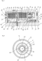
- the Figures 1 to 7 show a double clutch unit 1 according to the invention in accordance with a first embodiment, which can also be referred to as a clutch arrangement.
- the double clutch unit 1 is used in particular in the drive train of a motor vehicle for variable torque distribution from an input part, here an outer disk carrier 2, to two output parts, here a first inner disk carrier 3 and a second inner disk carrier 4.
- the outer disk carrier 2 and the two inner disk carriers 3 are arranged so as to be rotatable about an axis of rotation X.
- the outer disk carrier 2 can, for example, be driven in rotation via a ring gear.
- the double clutch unit 1 has two separately controllable friction clutches 5, 6, the transmittable torque of which can be individually variably adjusted.
- the dual clutch unit 1 suitable for actively controlling the yaw motion of the motor vehicle or the yaw angle speed. This is achieved by distributing or specifically adjusting the torque differently on a right output shaft, which is also referred to as the side shaft 50, and on a left output shaft, which is also referred to as the side shaft 60, of a driven axle.
- Such systems for variable torque distribution are also referred to as “torque vectoring” systems or “active yaw” systems.
- the control principle is also referred to as active torque distribution or "torque vectoring”.
- the first inner disk carrier 3 is here non-rotatably connected to the right side shaft 50 and the second inner disk carrier 4 to the left side shaft 60 of the driven axle Accordingly, the two inner disk carriers 3, 4 can also be referred to as clutch hubs.
- the two friction clutches 5, 6 are arranged axially next to one another and concentrically to the rotation axis X. They are preferably designed identically in terms of their structure, in particular their geometric dimensions. Specifically, the friction clutches 5, 6 each have a disk pack 7, 8. The first disk pack 7 is used for variable torque transmission between the outer disk carrier 2 and the first inner disk carrier 3, while the second disk pack 8 is used for variable torque transmission between the outer disk carrier 2 and the second inner disk carrier 4.
- the two disk packs 7, 8 can be individually subjected to force, so that the torque to be transmitted to the respective side shaft 50, 60 can be precisely adjusted as required.
- the disk packs 7, 8 each comprise a plurality of outer disks which are rotationally fixed and axially movable with the outer disk carrier 2, as well as a plurality of inner disks which are rotationally fixed and axially movable with the associated inner disk carrier 3, 4, which are arranged axially alternately.
- the two disk packs 7, 8 can each be axially loaded towards one another by an associated pressure plate 9, 10 and are each axially supported against an associated support element 11, 12.
- the two support elements 11, 12, which are arranged axially between the two disk packs 7, 8, are in turn axially supported against the outer disk carrier 2.
- the support elements 11, 12 are ring-shaped and arranged concentrically to the axis of rotation X.
- the two support elements 11, 12 engage axially with one another and are axially supported independently of one another against the outer disk carrier 2.
- the double clutch unit 1 has a clutch chamber 13 which is delimited radially on the outside by the outer disk carrier 2 and radially on the inside by the two inner disk carriers 3, 4. Furthermore, a right cover 14 and a left cover 15 are provided which laterally delimit the clutch chamber 13.
- the two covers 14, 15 are connected to the outer disk carrier 2 in a rotationally fixed manner and each have a central opening 16, 17 for receiving the right or left side shaft 50, 60. Between the covers 14, 15 and the A plain bearing is provided for the respective side shaft 50, 60.
- the first disk pack 7, the first support element 11, the second support element 12 and the second disk pack 8 are accommodated in the clutch chamber 13.
- Each of the two friction clutches 5, 6 can be individually actuated by an associated actuator unit 18, 19.
- the two actuator units 18, 19 can be controlled independently of one another by means of a control unit (not shown), so that a first torque that can be transmitted from the first disk pack 7 to the first inner disk carrier 3 and a second torque that can be transmitted from the second disk pack 8 to the second inner disk carrier 4 can be variably adjusted independently of one another.
- the two actuator units 18, 19 are designed in the same way in terms of their structure and function.
- the actuator units 18, 19 can be hydraulic or electric actuator units, in particular electrohydraulic, electromotor or electromagnetic actuator units.
- the actuators are each supported axially on a clutch housing 20 in opposite axial directions.
- the hydraulically operated actuators here each have an annular piston 21 which is seated axially displaceably in an associated annular cylinder chamber 22 of the clutch housing 20.
- An opening 23 is formed in the laterally arranged covers 14, 15 of the outer disk carrier 2, through which the respective piston 21 interacts with the associated pressure plate 9, 10 to actuate the respective friction clutch 5, 6.
- a hydraulic pressure can be generated via oil channels (not shown here) by means of a hydraulic pump, so that the respective piston 21 is moved axially in the direction of the disk pack 7, 8.
- Return springs 24 are provided here to return the pistons 21.
- the friction clutches 5, 6 are designed in particular as wet-running multi-disk clutches.
- the disk packs 7, 8 are supplied with coolant and/or lubricant, which is referred to below as coolant, which is discharged into the clutch chamber 13 via outlet channels 25', 25" designed in the inner disk carriers 3, 4.
- coolant which is discharged into the clutch chamber 13 via outlet channels 25', 25" designed in the inner disk carriers 3, 4.
- the coolant discharged from the radial inside is passed through the disk packs 7, 8 by the centrifugal forces and via Outer disk carrier 2 designed drainage channels 26 divert radially outwards.
- the respective channels 25', 25", 26 are each arranged in a tooth base of a tooth gap of the inner disk carrier 3, 4 or the outer disk carrier 2.
- the outlet channels 25', 25" of the respective inner disk carrier 3, 4 can be axially offset from the drainage channels 26 in the outer disk carrier 2, as shown in Figure 3 is shown.
- the coolant is discharged downwards into a sump 67 due to an inclined top of the clutch housing 20.
- a conveying device (not shown) can be present which feeds the coolant from the sump 67 to a central oil supply 27.
- the coolant can be conveyed, for example, by the hydraulic pump which is already used to actuate the friction clutches 5, 6.
- a separate pump can be used for active conveying, or a gear with a separator can be used for passive conveying.
- the central oil supply 27 has a feed channel 28 formed in the clutch housing 20.
- the feed channel 28 is designed as a radially extending channel through which the coolant, which is pumped here, flows from the radial outside to the radial inside.
- a deflection ring 30 At the radially inner end of the feed channel 28, it opens into a collecting groove 29 of a deflection ring 30, which runs in the circumferential direction around the axis of rotation X.
- the deflection ring 30 is in the Figures 5 to 7 shown in detail. The deflection ring 30 is inserted in a recess of the clutch housing 20 and largely seals the feed channel 28 to the side shaft 50.
- the deflection ring 30 is held stationary relative to the clutch housing 20 and has a central opening 31 for receiving the right side shaft 50, here, with play.
- a wall 32 axially delimiting the collecting groove 29 and running around in the circumferential direction, several transfer holes 33 are designed which are distributed in the circumferential direction and are aligned in the axial direction.
- the transfer bores 33 are positioned radially further inward than a bottom 34 of the collecting groove 29 and thus form a channel-shaped inlet area 35 in the area of the collecting groove 29.
- the right cover 14 is arranged axially between the deflection ring 30 and the first inner disk carrier 3 and is connected in a rotationally fixed manner to the outer disk carrier 2.
- the cover 14 several circumferentially distributed Transfer holes 36 are formed which are axially aligned.
- a first rotary feedthrough 37 is provided in order to connect the transfer holes 33 to the transfer holes 36 in a fluid-conducting manner.
- the first rotary feedthrough 37 is formed by an axial projection 38 of the deflection ring 30 and by an annular space 39 of the cover 14 which is open towards the deflection ring 30.
- the annular space 39 is radially delimited between a radially outer wall 40 of the cover 14 and the surface of the right-hand side shaft 50.
- the deflection ring 30 protrudes into the annular space 39 with its axial projection 38.
- the transfer holes 33 of the deflection ring 30 and the transfer holes 36 of the cover 14 are arranged in such a way that they are temporarily connected to one another in a fluid-conducting manner at least once, here sixteen times, during one rotation of the cover 14 about the axis of rotation X.
- Sixteen transfer bores 33 and sixteen takeover bores 36 are provided here purely as an example, although in principle more or fewer than sixteen bores can be provided.
- the number of transfer bores 33 can also differ from the number of takeover bores 36.
- the transfer holes 36 open into a first distribution channel 41, which is formed in the first inner disk carrier 3.
- the first distribution channel 41 is formed as an axially extending annular gap, which is radially delimited by a radially inner channel wall 44 of the first inner disk carrier 3 and a radially outer channel wall 45 of the first inner disk carrier 3.
- the cover 14 has an axial projection 42, which projects into the first distribution channel 41 through a lateral inlet opening 43 of the latter.
- the inlet opening 43 is ring-shaped.
- the outer radius of the projection 42 is correspondingly smaller than the radial distance of the radially outer channel wall 45 from the axis of rotation X.
- a second rotary feedthrough 51 is formed by the axial projection 42 of the cover 14 and the section of the first distribution channel 41 that axially overlaps with the projection 42 in order to connect the transfer holes 36 to the first distribution channel 41 in a fluid-conducting manner.
- the transfer holes 36 of the cover 14 exit through transfer openings 46 that are formed on an axial side of the cover 14 facing the first inner disk carrier 3.
- the transfer openings 46 are axially spaced from an end face 47 of the axial projection 42 and set back relative to it. Between the end face 47 and the front side, in which the transfer openings 46 are located, an annular space 48 is formed, via which the coolant is guided into the first distribution channel 41.
- the wall 40 of the cover 14 is chamfered in the area of the annular space 48, with the chamfer opening towards the first distribution channel 41.
- the channel wall 44 which radially inwardly delimits the first distribution channel 41 is also chamfered, with the chamfer of the inner channel wall 44 running parallel to the chamfer of the wall 40 of the annular space 48.
- the transfer holes 36 run radially further inwards compared to the first distribution channel 41, so that the coolant flows into the first distribution channel 41 along the chamfered wall 40 due to centrifugal forces.
- a surface of the radially outer channel wall 45 lies in an imaginary lateral surface which limits the first distributor channel 41 radially on the outside.
- the lateral surface is frustoconical.
- the radially inner channel wall 44 runs parallel to the axis of rotation X.
- the distance of the radially outer lateral surface from the axis of rotation X increases in the axial direction.
- the first distributor channel 41 widens radially outwards in the flow direction of the coolant.
- the flow direction is in Figure 2 indicated by the arrow F.
- An opening angle ⁇ between the surface lines M of the surface and the axis of rotation X is, here, approximately 2°, whereby the opening angle ⁇ preferably opens in the flow direction F of the coolant, that is, in a direction towards the second distribution channel 52.
- the opening angle ⁇ between one of the surface lines M and the axis of rotation X is shown using a parallel projection P of the axis of rotation X.
- Outlet openings 53 are formed in the radially outer channel wall 45 of the first distribution channel 41, which open into the outlet channels 25' in the first distribution channel 41.
- the outlet openings 53 are arranged on an imaginary spiral arranged concentrically to the axis of rotation X.
- the diameter of the respective outlet openings 53 increases in the flow direction F. Accordingly, the outlet opening 53 closest to the inlet opening 43 has the smallest diameter and the outlet opening 53 has the largest diameter.
- the diameter of the respective outlet channels 26 in the outer disk carrier 2 can also be designed accordingly in order to avoid a local undersupply, To prevent oversupply or a blockage of the coolant and lubricant.
- at least a subset of the drainage channels 26 along the first lamella pack 7 can have a smaller diameter than at least a subset of the drainage channels 26 along the second lamella pack 8.
- the first distribution channel 41 opens into a plurality of through-bores 54 distributed in the circumferential direction.
- the through-bores 54 are formed in the first inner disk carrier 3.
- a longitudinal bore axis L of the respective through-bores 54 forms an angle with the axis of rotation X that corresponds to the opening angle ⁇ .
- a plurality of recesses 55 formed at a distance from one another in the circumferential direction are provided in the radially outer channel wall 45 of the first distribution channel 41.
- the recesses 55 extend in the axial direction, with the recesses 55 starting at the inlet opening 43 and each opening into one of the through-bores 54, here flush.
- the recesses 55 have a constant depth over their length.
- Four of the through-bores 54 and correspondingly four of the recesses 55 in the first inner disk carrier 3 are shown here purely as an example.
- the through-bores 54 extend through an axial projection 56 of the first inner disk carrier 3, which projects into the second distribution channel 52 through an annular opening 49 of the second inner disk carrier 4, which is arranged concentrically to the axis of rotation X.
- the second distribution channel 52 is formed as an axially extending annular gap, which is delimited by a radially inner channel wall 62 of the second inner disk carrier 4 and a radially outer channel wall 57 of the second inner disk carrier 4.
- the outer radius of the projection 56 is smaller than the radial distance of the radially outer channel wall 57 of the second distributor channel 52 from the rotation axis X.
- the through holes 54 emerge at a front side 58 of the axial projection 56 and thus open into the second distributor channel 52.
- a third rotary feedthrough 59 is thus formed by the axial projection 56 of the first inner disk carrier 3 and the section of the second distributor channel 52 that axially overlaps with the projection 56 in order to connect the through holes 54 to the second distributor channel 52 in a fluid-conducting manner.
- a ring 61 is pushed onto the axial projection 56 of the first inner disk carrier 3.
- the second inner disk carrier 4 is supported axially on the first inner disk carrier 3 via the ring 61.
- the ring 61 can therefore also be used as a
- the ring 61 has a sliding surface and can be a bronze ring, for example.
- the radially inner channel wall 62 of the second distributor channel 52 and an outer wall 63 of the projection 56 of the first inner disk carrier 3 facing the inner channel wall 62 have chamfers 64, 65 that run in opposite directions.
- the chamfers 64, 65 are axially spaced from one another, the axial distance corresponding at least approximately to the thickness of the ring 61.
- the lateral surface is, like that of the first distributor channel 41, frustoconical.
- the radially inner channel wall 62 runs parallel to the axis of rotation X.
- the second distributor channel 52 also widens radially outwards in the flow direction of the coolant.
- the flow direction is in Figure 2 indicated by the arrow F. Due to the increasing distance in the axial direction between the radially outer surface and the rotation axis X, the coolant is conveyed through the second distributor channel 52 by the centrifugal force on the radially outer channel wall 62.
- the opening angle ⁇ between the surface lines M of the surface of the second distributor channel 52 and the rotation axis X and the opening angle ⁇ between the surface lines M of the surface of the first distributor channel 41 and the rotation axis X is, here, identical, i.e. approximately 2°. Both opening angles ⁇ open in the flow direction F of the coolant.
- Outlet openings 66 are also formed in the radially outer channel wall 57 of the second distributor channel 52, which open into the outlet channels 25" in the second inner disk carrier 4.
- the outlet openings 66 are arranged on an imaginary spiral concentric to the axis of rotation X.
- the diameter of the respective outlet openings 66 increases in the flow direction F. Accordingly, the outlet opening 66 closest to the ring opening 49 has the smallest diameter, with the outlet opening 66 furthest away from the ring opening 49 having the largest diameter.
- the second distribution channel 52 is closed at an end 68 facing away from the ring opening 49. Thus, when the second inner disk carrier 4 rotates, the Coolant flowing through the second distribution channel 52 only leaves the latter via the outlet channels 25" to lubricate the second disk pack 8.
- the coolant is conveyed from the sump 67 to the central oil supply 27, for example by means of an oil pump (not shown), and is pumped radially inward through the feed channel 28 formed in the clutch housing 20.
- the coolant flows from the open end of the feed channel 28 into the collecting groove 29 of the deflection ring 30 and is axially deflected there by the axially aligned transfer holes 33.
- the coolant flows through the first rotary feedthrough 37 into the transfer holes 36 formed in the right cover 14, which rotate about the axis of rotation X when the outer disk carrier 2 rotates.
- the coolant flows through the second rotary feedthrough 51 into the first distribution channel 41.
- the coolant When the first inner disk carrier 3 rotates about the axis of rotation X, the coolant is pressed against the radially outer channel wall 45 due to the centrifugal forces and flows through the first distribution channel 41, which widens in the axial direction, in a direction towards the through holes 54.
- a first partial amount of the coolant passes through the outlet openings 53 arranged on the imaginary spiral into the outlet channels 25' to lubricate the first disk pack 7.
- a second partial amount of the coolant is fed directly to the through holes 54 via the groove-like recess 55. Consequently, no outlet openings 53 for the outlet channels 25' are formed in the recess 55.
- the second partial quantity of the coolant is thus pressed through the through holes 54 via the third rotary union 59 into the second distribution channel 52.
- the coolant When the second inner disk carrier 4 rotates about the rotation axis X, the coolant is pressed against the radially outer channel wall 57 due to the centrifugal forces and flows through the second distribution channel 52, which widens in the axial direction, in a direction towards the closed end 68 of the second distribution channel 52. On the way there, the coolant flows through the outlet openings 66 arranged on the imaginary spiral into the outlet channels 25" to lubricate the second disk pack 8. Then, when the first inner disk carrier 3 or the second inner disk carrier 4 rotates, the coolant flows through the respective disk pack 7, 8 and reaches the radially outer end of the clutch chamber 13 through the drain channels 26 formed in the outer disk carrier 2 back into the sump 67. For this purpose, the coolant flowing out of the drain channels 26 on a housing wall of the stationary clutch housing 20 into the sump 67.
- the Figure 8 shows an enlarged partial section of a dual clutch unit according to the invention in a modified embodiment.
- This embodiment largely corresponds to that according to the Figures 1 to 7 , to whose description reference is made.
- the same details are provided with the same reference numerals as in the Figures 1 to 7 .
- In the Figure 8 is to illustrate the only difference compared to the embodiment according to the Figures 1 to 7 , here, the first inner disk carrier 3 shown in detail.
- the radially outer channel wall 45 of the first distribution channel 41 runs parallel to the axis of rotation X and thus also parallel to the radially inner channel wall 44 of the first distribution channel 41.
- an Archimedean screw 69 is inserted in the first distribution channel 41, which is connected in a rotationally fixed manner to the first inner disk carrier 3.
- the Archimedean screw 69 is in the Figure 9 , to clarify its structure, shown as a single component.
- the Archimedean screw 69 has a cylindrical bore 70 so that the Archimedean screw 69 can be inserted through the inlet opening 43 into the first distribution channel 41.
- the inner diameter of the cylindrical bore 69 corresponds, at least approximately, to the outer diameter of the radially inner channel wall 44.
- the outer diameter of the Archimedean screw 69 corresponds, at least approximately, to the inner diameter of the radially outer channel wall 45. Chambers are formed between the individual blade sections of the Archimedean screw 69, in which the coolant can be screwed to the through-bores 54.
- the coolant is also guided past the outlet channels 25', through which a portion of the coolant is guided into the clutch chamber 13 for oiling the first disk pack 8.
- the from the embodiment according to the Figures 1 to 7 known recesses 55 together with the Archimedean screw 69.
- the second inner disk carrier 4 can also have an Archimedean screw 69. In this way, when the second inner disk carrier 4 rotates, the coolant flowing into the second distribution channel 52 from the first distribution channel 41 via the through holes 54 during operation can be fed to the outlet channels 25" in the second inner disk carrier 4 for oiling the second disk pack 8.
- the Figure 10 shows an enlarged partial section of a dual clutch unit according to the invention in a further embodiment.
- This embodiment largely corresponds to that according to the Figures 1 to 7 , to whose description reference is made.
- the same details are provided with the same reference numerals as in the Figures 1 to 7 .
- In the Figure 10 is to illustrate the only difference compared to the embodiment according to the Figures 1 to 7 , here, the first inner disk carrier 3 shown in detail.
- the first inner disk carrier 3 is different in that several first distribution channels 71 are provided.
- the first distribution channels 71 are designed as bores and are distributed in the circumferential direction around the axis of rotation X.
- the first distribution channels 71 extend from the inlet opening 43, which is shaped as an annular gap, to the individual through-bores 54.
- Each of the first distribution channels 71 opens into a through-bore 54 assigned to the respective first distribution channel 71.
- the pair of first distribution channel 71 and assigned through-bore 54 preferably forms a continuous bore with a common borehole longitudinal axis A.
- the respective borehole longitudinal axis A encloses an opening angle ⁇ with the axis of rotation X, which is approximately 2° here.
- the opening angle ⁇ preferably opens in the flow direction F of the coolant, that is to say in a direction away from the inlet opening 43.
- At least one outlet channel 25' is provided in the first distribution channels 71.
- each of the first distribution channels 71 has several of the outlet channels 25'.
- the outlet channels 25' are arranged on an imaginary spiral across all the first distribution channels 71.
- the outlet channels 25' can be aligned radially or skewed to the axis of rotation X.
- the ones from the embodiment according to the Figures 1 to 7 known recesses 55 in the individual first distribution channels 71 are used to convey a portion of the coolant past the outlet channels 25' to the through holes 54.
- the second inner disk carrier 4 can also have several of the holes distributed in the circumferential direction around the axis of rotation X, which form the second distribution channels.
- the second distribution channels are then, like the second distribution channel 52 according to the Figures 1 to 7 shown embodiment, closed at the ends 68 facing away from the first inner disk carrier 3.
- the coolant can only flow out of the second distribution channels into the second disk pack 8 via the outlet channels 25".
Landscapes
- Engineering & Computer Science (AREA)
- General Engineering & Computer Science (AREA)
- Mechanical Engineering (AREA)
- Chemical & Material Sciences (AREA)
- Combustion & Propulsion (AREA)
- Transportation (AREA)
- Hydraulic Clutches, Magnetic Clutches, Fluid Clutches, And Fluid Joints (AREA)
- Mechanical Operated Clutches (AREA)
Description
- Die Erfindung betrifft eine Doppelkupplungseinheit zur variablen Drehmomentverteilung auf zwei Ausgangswellen gemäß Oberbegriff nach Anspruch 1, die einen um eine Drehachse drehend antreibbaren Außenlamellenträger, einen ersten Innenlamellenträger, ein erstes Lamellenpaket zur Drehmomentübertragung zwischen dem Außenlamellenträger und dem ersten Innenlamellenträger, einen zweiten Innenlamellenträger, wobei der erste Innenlamellenträger und der zweite Innenlamellenträger relativ zueinander um die Drehachse drehbar angeordnet sind, und ein zweites Lamellenpaket zur Drehmomentübertragung zwischen dem Außenlamellenträger und dem zweiten Innenlamellenträger umfasst. Weiterhin betrifft die Erfindung eine Antriebsanordnung zum Antreiben einer Antriebsachse eines Kraftfahrzeuges mit einer solchen Doppelkupplungseinheit.
- Die eingesetzten Reiblamellenkupplungen oder Lamellenkupplungen sind jedoch Bauteile, die im Betrieb eines Kraftfahrzeuges hohen Temperaturen ausgesetzt sind. Insbesondere bei Lamellenpaketen, die aus mehreren Scheiben, den sogenannten Innenlamellen und Außenlamellen, bestehen, ist somit eine Kühlung der Reiblamellen mit einem Kühl- und/oder Schmiermittel erforderlich.
- Aus der
US 2 935 889 A ist eine Doppelkupplungseinheit zur Drehmomenteinleitung zweier Eingangswellen auf eine Ausgangswelle bekannt. Die Doppelkupplungseinheit umfasst: einen um eine Drehachse rotierend angetriebenen äußeren Kupplungsscheibenträger, der mit der Ausgangswelle verbunden ist; einen ersten inneren Kupplungsscheibenträger und einen zweiten inneren Kupplungsscheibenträger, wobei der erste innere Kupplungsscheibenträger und der zweite innere Kupplungsscheibenträger relativ zueinander um die Drehachse drehbar angeordnet sind. Der erste innere Kupplungsscheibenträger umfasst einen ersten Verteilerkanal und der zweite innere Kupplungsscheibenträger umfasst einen zweiten Verteilerkanal. Der erste innere Kupplungsscheibenträger weist ferner eine Durchgangsbohrung auf, die den zweiten Verteilerkanal mit dem ersten Verteilerkanal fluidisch verbindet. Die Durchgangsbohrung weist die Form eines geraden Zylinders auf, der parallel zur Drehachse angeordnet ist. - Aus der
US 3 734 259 A ist eine Doppelkupplungseinheit mit einem äußeren Kupplungsscheibenträger, einem ersten inneren Kupplungsscheibenträger, der eine Kupplungsscheibe trägt, und einem zweiten inneren Kupplungsscheibenträger, der zwei Kupplungsscheiben trägt, bekannt. In jeder der Kupplungsscheiben sind Öffnungen vorgesehen. - Aus der
US 2006/113157 A1 ist ein einzelner Kupplungsscheibenträger für eine Mehrscheibenkupplung bekannt, die einen äußeren zylindrischen Teil mit am Außenumfang ausgebildeten Nuten aufweist. Am Innenumfang des äußeren zylindrischen Teils ist eine innere Umfangsfläche ausgebildet. Die innere Umfangsfläche begrenzt einen Raum, der durch eine Wand in zwei konische Hälften geteilt ist. Die Wand erstreckt sich radial von dem äußeren zylindrischen Teil in Richtung eines inneren zylindrischen Nabenabschnitts. In dem Nabenabschnitt ist eine Durchtrittsbohrung eingebracht. - Aus der
US 2018/058513 A1 ist eine Anordnung für die geregelte Kühlung und/oder Schmierung von Lamellenpaketen von Kupplungen bekannt, die in einem Gehäuse angeordnet sind. Das Gehäuse umfasst eine mittlere Trennwand, die eine Radialwand und eine zentrale Nabe umfasst. Die Trennwand trennt das Gehäuse in zwei interne Kammern, in denen die Lamellenpakete angeordnet sind. Jedes Lamellenpaket kann verschachtelte Lamellen, wie Trennplatten, die an ihrem äußerem Umfang an dem Gehäuse befestigt oder verzahnt sind, und Reiblamellen, die mit den Trennplatten verschachtelt sind und mit ihrem inneren Umfang mit den Naben verzahnt sind, umfassen. - Aus der
WO 2017/157479 A1 ist eine Doppelkupplungseinheit zur variablen Drehmomentverteilung auf zwei Ausgangswellen bekannt. Die Doppelkupplungseinheit weist zwei Reibungskupplungen auf, wobei jeder der beiden Kupplungen eine eigene Kupplungsbeölungsleitung zugeordnet ist. - Aus der
EP 1 664 567 B1 ist eine Doppelkupplungseinheit bekannt, bei der ein gemeinsamer Innenlamellenträger angetrieben wird und zwei Außenlamellenträger unabhängig voneinander um die gemeinsame Drehachse drehbar angeordnet sind. Die beiden Lamellenpakete werden über Schmierölkanäle, die in dem gemeinsamen Innenlamellenträger integriert sind, mit Kühl- und/oder Schmiermittel versorgt. Über einen Ölkanal, der in Verlängerung zwischen den beiden Lamellenpaketen im Innenlamellenträger ausgebildet ist, wird das Kühl- und/oder Schmiermittel, ausgehend von der Nabe, radial nach außen in axial verlaufende Ringkanäle und schließlich in die beiden Lamellenpakte geführt. - Aufgabe der Erfindung ist es, eine Doppelkupplungseinheit der eingangs genannten Art zur Verfügung zu stellen, die bei geringstem Bauraum und Verschleiß sehr hohe Kräfte aufnehmen kann und auch dem Dauerbetrieb mit Schlupf standhält.
- Diese Aufgabe wird dadurch gelöst, dass bei der Doppelkupplungseinheit der eingangs genannten Art eine Bohrlochlängsachse der zumindest einen Durchtrittsbohrung mit der Drehachse einen Bohrungswinkel einschließt.
- Das Kühlmittel dient der Kühlung und/oder Schmierung der Lamellenpakete, sodass das Kühlmittel auch als Kühl- und/oder Schmiermittel bezeichnet werden könnte. Üblicherweise wird hierfür ein ölhaltiges Kühlmittel verwendet.
- Der erste Verteilerkanal hat somit eine Doppelfunktion, erstens, die Versorgung des ersten Lamellenpaktes mit Kühlmittel und, zweitens, die teilweise Weiterleitung des Kühlmittels in den zweiten Verteilerkanal. Damit ist der zweite Verteilerkanal in Flussrichtung des Kühlmittels dem ersten Verteilerkanal nachgeschaltet. Entsprechend strömt das von der zentralen Ölzufuhr kommende Kühlmittel zunächst durch den ersten Verteilerkanal und lediglich eine Teilmenge des Kühlmittels wird durch den ersten Verteilerkanal in den zweiten Verteilerkanal weitergeleitet. Damit sind die beiden Verteilerkanäle in Reihe geschaltet. Durch die Reihenschaltung der beiden Verteilerkanäle in Flussrichtung des Kühlmittels hintereinander ergibt sich eine kompakt bauende Doppelkupplungseinheit.
- Vorzugsweise kann der erste Verteilerkanal über einen seitlichen Zugang mit Kühlmittel versorgt werden. Hierzu kann die Einlauföffnung an einer vom zweiten Innenlamellenträger abgewandten Stirnseite des ersten Innenlamellenträgers ausgebildet sein. Die Einlauföffnung kann eine ringförmige Öffnung sein, die konzentrisch zur Drehachse angeordnet ist.
- Der erste Verteilerkanal ist im ersten Innenlamellenträger und der zweite Verteilerkanal ist im zweiten Innenlamellenträger ausgebildet. Die beiden Innenlamellenträger sind relativ zueinander um die gemeinsame Drehachse drehbar angeordnet, beispielsweise in einem Kupplungsgehäuse, sodass im Betrieb der Doppelkupplungseinheit die beiden Innenlamellenträgern, je nach Fahrzustand, mit unterschiedlichen Drehzahlen um die Drehachse rotieren können. Um den ersten Verteilerkanal selbst bei Drehzahlunterschieden mit dem zweiten Verteilerkanal flüssigkeitsleitend zu verbinden, kann eine Drehdurchführung vorgesehen sein. Hierzu kann der erste Innenlamellenträger einen axialen Vorsprung mit der zumindest einen Durchtrittsbohrung aufweisen. Axial bedeutet in Richtung der Drehachse, respektive entlang der Drehachse, insbesondere parallel zur Drehachse. In bevorzugter Weise ist der zweite Verteilerkanal über die zumindest eine Durchtrittsbohrung mit dem ersten Verteilerkanal flüssigkeitsleitend verbunden. Entsprechend kann vorgesehen sein, dass das von der zentralen Ölzufuhr kommende Kühlmittel zunächst durch den ersten Verteilerkanal strömt und eine Teilmenge des Kühlmittels durch die zumindest eine Durchtrittsbohrung in den zweiten Verteilerkanal weitergeleitet wird.
- Vorzugsweise erstrecken sich mehrere der Durchtrittsbohrungen durch den Vorsprung, insbesondere zwei, drei, vier, fünf, sechs oder mehr als sechs Durchtrittsbohrungen. Die Durchtrittsbohrungen können in Umfangsrichtung um die Drehachse verteilt angeordnet sein. Die zumindest eine Durchtrittsbohrung kann an einer dem zweiten Verteilerkanal zugewandten Stirnseite jeweils eine Auslassöffnung aufweisen. Zweckmäßigerweise ragt der Vorsprung in den zweiten Verteilerkanal hinein. Damit kann die zumindest eine Durchtrittsbohrung in Flussrichtung ausgangsseitig direkt in den zweiten Verteilerkanal münden. In Flussrichtung eingangsseitig kann der erste Verteilerkanal direkt in die zumindest eine Durchtrittsbohrung münden. Vorzugsweise kann ein Außendurchmesser des Vorsprungs kleiner als ein Außendurchmesser des zweiten Verteilerkanals oder gleich dem Außendurchmesser des zweiten Verteilerkanals sein. Ein Innendurchmesser des Vorsprungs kann größer als ein Innendurchmesser des zweiten Verteilerkanals oder gleich dem Innendurchmesser des zweiten Verteilerkanals sein. Zweckmäßigerweise ist der zweite Verteilerkanal zumindest in einem Bereich axialer Überlappung mit dem Vorsprung, das heißt entlang desjenigen Bereiches, in dem der Vorsprung in den zweiten Verteilerkanal hineinragt, als ein sich in axialer Richtung erstreckender Ringspalt gestaltet. Auf diese Weise können die beiden Innenlamellenträger relativ zueinander um die Drehachse drehen. Im Ergebnis bilden der Vorsprung des ersten Innenlamellenträgers, mit der zumindest einen Durchtrittsbohrung, und der zweite Verteilerkanal, im Bereich der axialen Überlappung mit dem Vorsprung, gemeinsam die Drehdurchführung.
- Vorzugsweise stützen sich der erste Innenlamellenträger und der zweite Innenlamellenträger axial gegeneinander ab. Dadurch ergibt sich eine besonders geringe Baubreite. Axial zwischen den beiden Innenlamellenträgern kann ein Abstandhalter angeordnet sein. Der Abstandhalter kann ein konzentrisch zur Drehachse und den beiden Innenlamellenträgern angeordneter ringförmiger Körper sein. Aufgrund der Drehzahlunterschiede zwischen den beiden Innenlamellenträgern, die im Betrieb der Doppelkupplungseinheit vorliegen können, weist der Abstandhalter vorzugsweise eine gleitfähige Oberfläche auf. Der Abstandhalter kann auf den Vorsprung des ersten Innenlamellenträgers aufgeschoben sein. Weiterhin kann der Abstandhalter eine Dichtfunktion übernehmen und den Übergang zwischen dem ersten Innenlamellenträger und dem zweiten Innenlamellenträger radial nach außen abdichten. Radial bedeutet entlang einer Achse, die in einer Ebene senkrecht zur Drehachse liegt. Der Abstandhalter kann insbesondere aus einem Bronzematerial, aus einem Material auf Bronzebasis, einem Sintermaterial, insbesondere Sinter-Bronze oder dergleichen hergestellt sein.
- Gemäß einem Aspekt der vorliegenden Erfindung kann der erste Verteilerkanal und/oder der zweite Verteilerkanal jeweils als ein sich in axialer Richtung erstreckender und konzentrisch zur Drehachse angeordneter Ringspalt ausgebildet sein. Aufgrund der Zentrifugalkräfte wird das Kühlmittel gegen eine radial äußere Kanalwand des jeweiligen Verteilerkanals gedrückt. Alternativ zur Ausgestaltung des ersten Verteilerkanals und/oder des zweiten Verteilerkanals als Ringspalt kann der erste Innenlamellenträger und/oder der zweite Innenlamellenträger mehrere in Umfangsrichtung um die Drehachse verteilt angeordnete Verteilerkanäle aufweisen. Somit können mehrere der ersten Verteilerkanäle und/oder mehrere der zweiten Verteilerkanäle vorgesehen sein. Die Verteilerkanäle können jeweils als Bohrungen ausgebildet sein, die sich in axialer Richtung erstrecken. Um das Kühlmittel bei Rotation des jeweiligen Innenlamellenträgers zu fördern, können die als Bohrungen ausgestalteten Verteilerkanäle schräg zur Drehachse verlaufen. Insbesondere können durch die Verteilerkanäle gebildete Bohrlochlängsachsen mit der Drehachse jeweils einen Winkel einschließen. Der Winkel kann zwischen 0,01 ° und 10° liegen. Der jeweilige Winkel öffnet sich vorzugsweise sich in Flussrichtung des Kühlmittels. Die Bohrlochlängsachsen der Verteilerkanäle können denselben Winkel mit der Drehachse einschließen. Grundsätzlich kann sich der Winkel der Bohrlochlängsachsen der Verteilerkanäle im ersten Innenlamellenträger auch von dem Winkel der der Bohrlochlängsachsen der Verteilerkanäle im zweiten Innenlamellenträger zur Drehachse unterscheiden.
- Zweckmäßigerweise sind in der radial äußeren Kanalwand des ersten Verteilerkanals und in der radial äußeren Kanalwand des zweiten Verteilerkanals jeweils Austrittsöffnungen ausgebildet, die in die Austrittskanäle des jeweiligen Innenlamellenträgers münden. Besonders gute Ergebnisse hinsichtlich einer gleichmäßigen Kühl- und/oder Schmierung der beiden Lamellenpakte wurden erzielt, wenn die Austrittsöffnungen auf einer konzentrisch zur Drehachse angeordneten, gedachten Spirale ausgebildet sind. Im Betrieb der Doppelkupplungseinheit hat sich gezeigt, dass die Zufuhr des Kühlmittels über die seitlich am ersten Innenlamellenträger ausgebildete Einlauföffnung des ersten Verteilerkanals zu einer Überversorgung des ersten Lamellenpaktes führen kann. Um die Kühlmittelversorgung lokal anzupassen, kann der Durchmesser der Austrittsöffnungen im ersten Lamellenträger sowie im zweiten Lamellenträger variiert werden. Insbesondere kann der Durchmesser der gesamten Austrittskanäle variiert werden. Weiterhin kann zumindest eine Teilmenge der Austrittsöffnungen beziehungsweise der Austrittskanäle im ersten Verteilerkanal einen kleineren Durchmesser aufweisen als zumindest eine Teilmenge der Austrittsöffnungen beziehungsweise der Austrittskanäle im zweiten Verteilerkanal. Die Austrittskanäle verlaufen vorzugsweise in radialer Richtung.
- Weiterhin kann eine den ersten Verteilerkanal radial außenseitig begrenzende Mantelfläche und/oder eine den zweiten Verteilerkanal radial außenseitig begrenzende Mantelfläche kegelstumpfförmig ausgebildet sein. Die Achse des jeweiligen Kegelstumpfes ist in bevorzugter Weise die gemeinsame Drehachse, um die die beiden Innenlamellenträger und der Außenlamellenträger drehbar angeordnet sind. Vorzugsweise weitet sich der jeweilige insbesondere ringspaltförmige Verteilerkanal in Flussrichtung des Kühlmittels radial nach außen auf. Durch den in axialer Richtung zunehmenden Abstand der radial außenseitigen Mantelfläche wird das Kühlmittel durch die Zentrifugalkraft an der radial äußeren Kanalwand durch den jeweiligen Verteilerkanal gefördert, und zwar in einer Richtung weg von der Einlauföffnung. Insbesondere beträgt ein Öffnungswinkel zwischen Mantellinien der jeweiligen Mantelfläche und der Drehachse zwischen 0,01 ° und 10°. Der jeweilige Öffnungswinkel öffnet sich vorzugsweise sich in Flussrichtung des Kühlmittels.
- Anstatt der sich in axialer Richtung radial aufweitenden Ausgestaltung des jeweiligen Verteilerkanals kann die jeweilige radiale äußere Kanalwand des ersten Verteilerkanals und/oder des zweiten Verteilerkanals auch parallel zur Drehachse ausgerichtet sein. In dem jeweiligen Verteilerkanal kann jeweils eine archimedische Schraube angeordnet sein. Die archimedische Schraube kann wie eine Schneckenpumpe das Kühlmittel bei Rotation des jeweiligen Innenlamellenträgers in dem jeweiligen Verteilerkanal fördern. Die jeweilige archimedische Schraube ist in dem zugeordneten Verteilerkanal mit dem ersten Innenlamellenträger beziehungsweise dem zweiten Innenlamellenträger drehfest verbunden.
- Vorzugsweise ist der zweite Verteilerkanal an einem dem ersten Innenlamellenträger abgewandten axialen Ende verschlossen. Somit kann das Kühlmittel den zweiten Verteilerkanal in bevorzugter Weise ausschließlich über die Austrittskanäle verlassen.
- Vorzugsweise ist vorgesehen, dass das Kühlmittel den ersten Verteilerkanal ausschließlich über die Austrittskanäle im ersten Innenlamellenträger und über die zumindest eine Durchtrittsbohrung verlassen kann. Die Austrittskanäle schließen sich vorzugsweise unmittelbar an den zugehörigen Verteilerkanal an und sind radial zwischen dem jeweiligen Verteilerkanal und dem zugehörigen Lamellenpaket angeordnet.
- Des Weiteren können in dem ersten Verteilerkanal Leitmittel zur Leitung einer Teilmenge des Kühlmittels hin zur zumindest einen Durchtrittsbohrung ausgebildet sein. Dadurch wird gewährleistet, dass in dem in Flussrichtung dem ersten Verteilerkanal nachgeordneten zweiten Verteilerkanal stets eine Teilmenge des Kühlmittels ankommt, um eine Unterversorgung des zweiten Lamellenpaktes beziehungsweise eine Überversorgung des ersten Lamellenpaktes zu vermeiden. Die Leitmittel können mindestens eine insbesondere längliche Vertiefung, wie eine Nut, Rille, Rinne oder dergleichen, aufweisen. Insbesondere weist die zumindest eine Vertiefung eine konstante Tiefe über deren Länge auf. Die zumindest eine Vertiefung kann in der radial äußeren Kanalwand des ersten Verteilerkanals ausgebildet sein. Die mindestens eine Vertiefung kann sich über mindestens 20% der axialen Längserstreckung des ersten Verteilerkanals erstrecken. Vorzugsweise erstreckt sich die mindestens eine Vertiefung über mehr als 70% der Längserstreckung des ersten Verteilerkanals, wobei sich die mindestens eine Vertiefung über die gesamte Längserstreckung des ersten Verteilerkanals erstrecken kann. Die zumindest eine Vertiefung kann in der zumindest einen Durchtrittsbohrung münden. Vorteilhafterweise ist einer jeden Durchtrittsbohrung eine eigene Vertiefung zugeordnet. Beispielsweise kann der erste Innenlamellenträger mehrere in Umfangsrichtung angeordnete Durchtrittsbohrungen, insbesondere zwei, drei, vier, fünf, sechs oder mehr Durchtrittsbohrungen aufweisen, wobei in einer jeden Durchtrittsbohrung genau eine Vertiefung münden kann. Somit kann die Anzahl an Durchtrittsbohrungen und die Anzahl an Vertiefungen gleich sein.
- Zweckmäßigerweise schließt sich die zumindest eine Durchtrittsbohrung radial außen mit der radial äußeren Kanalwand, insbesondere mit der zugehörigen Vertiefung an, um einen stufenlosen Übergang zwischen dem ersten Verteilerkanal und der zumindest einen Durchtrittsbohrung bereitzustellen. Eine Bohrlochlängsachse der zumindest einen Durchtrittsbohrung kann mit der Drehachse einen Bohrungswinkel, der zwischen 0,01 ° und 10° beträgt, einschließen. Insbesondere sind der Bohrungswinkel und der Öffnungswinkel der Mantellinien der Mantelfläche des ersten Verteilerkanals identisch.
- In bevorzugter Weise weist der Außenlamellenträger mehrere Ablaufkanäle zum Abführen des Kühlmittels auf. Das von radial innen über die Austrittsbohrungen der Innenlamellenträger abgegebene Kühlmittel wird über die Zentrifugalkräfte durch die Lamellenpakte hindurchgeleitet, kühlt und/oder schmiert die einzelnen Lamellen, und gelangt schließlich zum Außenlamellenträger, wo es über die Ablaufkanäle nach radial außen abgeführt werden kann. Zumindest eine Teilmenge der Ablaufkanäle entlang des ersten Lamellenpaktes kann einen kleineren Durchmesser aufweisen als zumindest eine Teilmenge der Ablaufkanäle entlang des zweiten Lamellenpaktes. Auf diese Weise kann die Ablaufmenge an Kühlmittelversorgung lokal angepasst werden, um eine gleichmäßige Beölung beider Lamellenpakete zu erzielen. Das aus dem Außenlamellenträger ablaufende Kühlmittel kann über eine Gehäusewand eines Kupplungsgehäuses der Doppelkupplungseinheit zum Beispiel in einen Sumpf im Kupplungsgehäuse abfließen. Dort kann es über eine Fördereinrichtung der zentralen Ölzufuhr zugeführt werden. Die Fördereinrichtung kann insbesondere eine Pumpe oder ein drehendes Zahnrad mit einem Abstreifer sein, wobei das Zahnrad in den Sumpf eintauchen und der Abstreifer das Kühlmittel abstreifen kann.
- Weiterhin kann die Doppelkupplungseinheit einen Umlenkring aufweisen. Der Umlenkring kann, in Flussrichtung, eingangsseitig mit der zentralen Ölzufuhr und ausgangsseitig mit dem ersten Verteilerkanal flüssigkeitsleitend verbunden sein. Der Umlenkring kann konzentrisch zur Drehachse angeordnet sein. Vorzugsweise ist der Umlenkring in einer Ausnehmung eines Kupplungsgehäuses eingesetzt, respektive eingepresst und ist relativ zum Kupplungsgehäuse ortsfest gehalten. Somit dreht sich der Umlenkring im Betrieb der Doppelkupplungseinheit nicht um die Drehachse, sondern steht still. Der Umlenkring kann eine in Umfangsrichtung offen gestaltete Sammelnut und mehrere in Umfangsrichtung verteilt angeordnete Übergabebohrungen, die zumindest im Wesentlichen axial ausgerichtet und mit der Sammelnut flüssigkeitsleitend verbunden sind, aufweisen. Im Betrieb kann das von radial außerhalb dem Umlenkring zugeführte Kühlmittel in der Sammelnut den Umlenkring umspülen und über die Übergabebohrungen in axialer Richtung aus dem Umlenkring austreten. Dies ermöglicht eine axial kompakte Bauweise. Der Umlenkring kann zum Beispiel ein Kunststoffteil, insbesondere ein Spritzgussteil aus Kunststoff sein, wobei grundsätzlich auch metallische Materialien möglich sind.
- Des Weiteren kann seitlich am Außenlamellenträger eine Abdeckung drehfest angeordnet sein. In der Abdeckung kann zumindest eine Übernahmebohrung ausgebildet sein, die die zumindest eine Übergabebohrung des Umlenkringes mit dem ersten Verteilerkanal flüssigkeitsleitend verbindet. Im Betrieb der Doppelkupplungseinheit dreht sich die Abdeckung zusammen mit dem Außenlamellenträger um die Drehachse. Aufgrund der Drehzahlunterschiede gegenüber dem stillstehenden Umlenkring kann eine Drehdurchführung zur Fluidverbindung vorgesehen sein. Beispielsweise kann die Abdeckung mehrere in Umfangsrichtung um die Drehachse verteilt angeordnete Übernahmebohrungen aufweisen, wobei die Übernahmebohrungen der Abdeckung und die Übergabeöffnungen des Umlenkringes derart zueinander angeordnet sein können, dass sie während einer Umdrehung der Abdeckung um die Drehachse mindestens einmal vorübergehend flüssigkeitsleitend miteinander verbunden sind. Um den Fluid-übergang zwischen dem Umlenkring und der Abdeckung abzudichten, kann der Umlenkring in einen zum Umlenkring hin offen ausgebildeten Ringspalt eingreifen. Die Abdeckung wiederum kann zur Abdichtung des Fluidübergangs zwischen den Übernahmebohrungen und dem ersten Verteilerkanal einen axialen Vorsprung aufweisen, der in den ersten Verteilerkanal hineinragt. Der erste Verteilerkanal ist zumindest in einem Bereich axialer Überlappung mit dem Vorsprung der Abdeckung, das heißt entlang desjenigen Bereiches, in dem der Vorsprung in den ersten Verteilerkanal hineinragt, als ein sich in axialer Richtung erstreckender Ringspalt gestaltet. Auf diese Weise können die drehfest mit dem Außenlamellenträger verbundene Abdeckung und der erste Innenlamellenträger mit unterschiedlichen Drehzahlen um die Drehachse drehen. Da auch zwischen der Abdeckung und dem ersten Innenlamellenträger Drehzahlunterschiede auftreten können, kann hier ebenso eine Drehdurchführung zur Fluidverbindung vorgesehen sein. Anstatt der beschriebenen Anordnung der Abdeckung zwischen dem Umlenkring und dem ersten Innenlamellenträger kann der Umlenkring auch unmittelbar in den ersten Verteilerkanal hineinragen, sodass durch die einander axial überlappenden Bereiche des Umlenkringes und des ersten Innenlamellenträgers eine Drehdurchführung gebildet sein kann.
- Die Drehmomentübertragung zwischen dem Außenlamellenträger und dem jeweiligen Innenlamellenträger kann in beide Richtungen erfolgen. Im regulären Betrieb treibt ein Antriebsmotor den Außenlamellenträger drehend an, sodass das Drehmoment vom Außenlamellenträger über das erste Lamellenpaket auf den ersten Innenlamellenträger und/oder über das zweite Lamellenpaket auf den zweiten Innenlamellenträger übertragen werden kann. Bei Einsatz eines Generators im Antriebsstrang, beispielsweise eine elektrischer Antrieb, der sowohl als Motor als auch als Generator arbeiten kann, kann zur Energierückgewinnung der Drehmomentfluss umgekehrt sein, sodass Drehmoment von dem ersten Innenlamellenträger über das erste Lamellenpaket und/oder vom zweiten Innenlamellenträger über das zweite Lamellenpaket auf den Außenlamellenträger übertragen werden kann.
- Die Doppelkupplungseinheit ermöglicht eine variable Drehmomentverteilung auf die beiden Ausgangswellen insbesondere eines Kraftfahrzeuges. Ein Differentialgetriebe zur Drehmomentverteilung auf die beiden Ausgangswellen ist damit nicht erforderlich. Zur variablen Drehmomentverteilung kann die Doppelkupplungseinheit zwei separat steuerbare Reibungskupplungen aufweisen, deren übertragbares Drehmoment individuell variabel einstellbar ist. Je nach Fahrzustand kann das Drehmoment an einem kurveninneren beziehungsweise an einem kurvenäußeren Rad individuell eingestellt werden, was insgesamt zu einer verbesserten Fahrdynamik, respektive Fahrstabilität führt. Bei Geradeausfahrt können beide Reibungskupplungen geschlossen sein. Der Drehzahlausgleich bei Kurvenfahrt kann dann durch Durchrutschen der Reibungskupplungen ermöglicht werden. Je enger die Kurve, je stärker das Durchrutschen. Werden die Kupplungen hingegen fest geschlossen, entspricht das einer 100-Prozent-Sperre. Somit kann mittels der Doppelkupplungseinheit die Antriebskraft stufenlos für jedes Rad geregelt werden. Dieses Steuerungsprinzip wird auch als aktive Momentenverteilung oder "Torque vectoring" bezeichnet. Dies kann im Rahmen einer fahrdynamischen Abstimmung des Fahrzeuges gezielt ausgenutzt werden, um eine ungewollte Neigung des Fahrzeuges zum Untersteuern durch ein positives Giermoment abzumindern. Des Weiteren kann die Fahrzeugdynamik auch durch einen gesteuerten Drehzahlunterschied zwischen einer Vorderachse und einer Hinterachse des Kraftfahrzeuges positiv beeinflusst werden. Ebenso können, vergleichbar zu einem Sperrdifferential, die beiden Fahrzeugräder durch synchrones Ansteuern der Kupplung miteinander verbunden werden. Dies führt zu einer deutlich verbesserten Traktion und kann im oberen Geschwindigkeitsbereich zu einer Gierdämpfung genutzt werden.
- Eine Lösung der oben genannten Aufgabe besteht weiter in einer Antriebsanordnung zum Antreiben einer Antriebsachse eines Kraftfahrzeuges, umfassend: eine Antriebsmaschine mit einer Motorwelle, zwei konzentrisch zueinander angeordnete Ausgangswellen und eine im Leistungspfad zwischen der Antriebsmaschine und den zwei Ausgangswellen angeordnete Kupplungseinheit, die nach zumindest einer der oben genannten Ausführungsformen gestaltet ist. Die Motorwelle treibt den Außenlamellenträger drehend an, und eine erste der beiden Ausgangswellen ist mit dem ersten Innenlamellenträger und eine zweite der beiden Ausgangswellen ist mit dem zweiten Innenlamellenträger drehfest verbunden. Mit der erfindungsgemäßen Antriebsanordnung ergeben sich dieselben Vorteile wie mit der erfindungsgemäßen Doppelkupplungseinheit, sodass diesbezüglich auf obige Beschreibung verwiesen wird.
- Bevorzugte Ausführungsbeispiele werden nachstehend anhand der Zeichnungsfiguren erläutert. Hierin zeigt:
- Figur 1
- eine erfindungsgemäße Doppelkupplungseinheit gemäß einer ersten Ausführungsform im Längsschnitt;
- Figur 2
- ein vergrößerter Teilausschnitt der Doppelkupplungseinheit nach
Figur 1 ; - Figur 3
- ein vergrößerter Teilausschnitt der Doppelkupplungseinheit nach
Figur 1 im Längsschnitt; - Figur 4
- die Doppelkupplungseinheit im Querschnitt;
- Figur 5
- ein Umlenkring in perspektivischer Ansicht;
- Figur 6
- der Umlenkring aus
Figur 5 in Seitenansicht; - Figur 7
- ein vergrößerter Teilausschnitt des Umlenkringes aus
Figur 5 im Längsschnitt; und - Figur 8
- ein vergrößerter Teilausschnitt einer Doppelkupplungseinheit gemäß einer zweiten Ausführungsform im Längsschnitt;
- Figur 9
- eine archimedische Schraube aus
Figur 8 im Längsschnitt; und - Figur 10
- ein vergrößerter Teilausschnitt einer Doppelkupplungseinheit gemäß einer dritten Ausführungsform im Längsschnitt.
- Die
Figuren 1 bis 7 , welche nachstehend gemeinsam beschrieben werden, zeigen eine erfindungsgemäße Doppelkupplungseinheit 1 gemäß einer ersten Ausführungsform, die auch als Kupplungsanordnung bezeichnet werden kann. Die Doppelkupplungseinheit 1 dient insbesondere zum Einsatz im Antriebsstrang eines Kraftfahrzeuges zur variablen Drehmomentverteilung von einem Eingangsteil, hier einem Außenlamellenträger 2, auf zwei Ausgangsteile, hier einem ersten Innenlamellenträger 3 und einem zweiten Innenlamellenträger 4. Der Außenlamellenträger 2 und die beiden Innenlamellenträger 3 sind drehbar um eine Drehachse X angeordnet. Der Außenlamellenträger 2 kann beispielsweise über ein Ringrad drehend antreibbar sein. Zur variablen Drehmomentverteilung weist die Doppelkupplungseinheit 1 zwei separat steuerbare Reibungskupplungen 5, 6, deren übertragbares Drehmoment individuell variabel einstellbar ist. - Damit eignet sich die Doppelkupplungseinheit 1 zur aktiven Steuerung der Gierbewegung des Kraftfahrzeugs beziehungsweise der Gierwinkelgeschwindigkeit. Dies wird dadurch bewerkstelligt, dass das Drehmoment auf eine rechte Ausgangswelle, die auch als Seitenwelle 50 bezeichnet wird, und auf eine linke Ausgangswelle, die auch als Seitenwelle 60 bezeichnet wird, einer angetriebenen Achse unterschiedlich verteilt beziehungsweise gezielt eingestellt wird. Derartige Systeme zur variablen Drehmomentverteilung werden auch als "Torque Vectoring"-Systeme oder "Active Yaw"-Systeme bezeichnet. Das Steuerungsprinzip wird auch als aktive Momentenverteilung oder "Torque Vectoring" bezeichnet.
- Der erste Innenlamellenträger 3 ist hier mit der rechten Seitenwelle 50 und der zweite Innenlamellenträger 4 mit der linken Seitenwelle 60 der angetriebenen Achse drehfest verbunden. Entsprechend können die beiden Innenlamellenträger 3, 4 auch als Kupplungsnaben bezeichnet werden.
- Die beiden Reibungskupplungen 5, 6 sind axial nebeneinander und konzentrisch zur Drehachse X angeordnet. Sie sind hinsichtlich ihres Aufbaus, insbesondere ihrer geometrischen Abmessungen vorzugsweise gleich gestaltet. Konkret weisen die Reibungskupplungen 5, 6 jeweils ein Lamellenpaket 7, 8 auf. Das erste Lamellenpaket 7 dient zur variablen Drehmomentübertragung zwischen dem Außenlamellenträger 2 und dem ersten Innenlamellenträger 3, während das zweite Lamellenpaket 8 zur variablen Drehmomentübertragung zwischen dem Außenlamellenträger 2 und dem zweiten Innenlamellenträger 4 dient. Die beiden Lamellenpakete 7, 8 sind individuell mit Kraft beaufschlagbar, sodass das auf die jeweilige Seitenwelle 50, 60 zu übertragende Drehmoment nach Bedarf genau eingestellt werden kann. Hierzu umfassen die Lamellenpakete 7, 8 jeweils mehrere mit dem Außenlamellenträger 2 drehfest und axial bewegliche Außenlamellen sowie mehrere mit dem zugehörigen Innenlamellenträger 3, 4 drehfest und axial bewegliche Innenlamellen, die axial abwechselnd angeordnet sind.
- Die beiden Lamellenpakete 7, 8 sind jeweils von einer zugehörigen Druckplatte 9, 10 axial in Richtung aufeinander zu beaufschlagbar und jeweils gegen ein zugehöriges Stützelement 11, 12 axial abgestützt. Die beiden Stützelemente 11, 12, welche entsprechend axial zwischen den beiden Lamellenpakten 7, 8 angeordnet sind, sind wiederum gegen den Außenlamellenträger 2 axial abgestützt. Die Stützelemente 11, 12 sind ringförmig gestaltet und konzentrisch zur Drehachse X angeordnet. Die beiden Stützelemente 11, 12 greifen axial ineinander und stützen sich unabhängig voneinander gegen den Außenlamellenträger 2 axial ab.
- Die Doppelkupplungseinheit 1 weist einen Kupplungsraum 13 auf, der radial außenseitig durch den Außenlamellenträger 2 und radial innenseitig durch die beiden Innenlamellenträger 3, 4 begrenzt ist. Weiterhin ist eine rechte Abdeckung 14 und eine linke Abdeckung 15 vorgesehen, die den Kupplungsraum 13 seitlich begrenzen. Die beiden Abdeckungen 14, 15 sind drehfest mit dem Außenlamellenträger 2 verbunden und weisen jeweils eine zentrale Öffnung 16, 17 zur Aufnahme der rechten beziehungsweise der linken Seitenwelle 50, 60 auf. Zwischen den Abdeckungen 14, 15 und der jeweiligen Seitenwelle 50, 60 ist eine Gleitlagerung vorgesehen. In dem Kupplungsraum 13 sind das erste Lamellenpaket 7, das erste Stützelement 11, das zweite Stützelement 12 und das zweite Lamellenpaket 8 aufgenommen.
- Jede der beiden Reibungskupplungen 5, 6 ist von einer zugehörigen Aktuatoreinheit 18, 19 individuell betätigbar. Hierfür sind die beiden Aktuatoreinheiten 18, 19 unabhängig voneinander mittels einer Steuereinheit (nicht dargestellt) steuerbar, sodass ein vom ersten Lamellenpaket 7 auf den ersten Innenlamellenträger 3 übertragbares erstes Drehmoment und ein vom zweiten Lamellenpaket 8 auf den zweiten Innenlamellenträger 4 übertragbares zweites Drehmoment unabhängig voneinander variabel einstellbar sind. Die beiden Aktuatoreinheiten 18, 19 sind hinsichtlich ihres Aufbaus und Funktionsweise gleich gestaltet.
- Die Aktuatoreinheiten 18, 19 können hydraulische oder elektrische Aktuatoreinheiten sein, insbesondere elektrohydraulische, elektromotorische oder elektromagnetische Aktuatoreinheiten. Die Aktuatoren stützen sich jeweils an einem Kupplungsgehäuse 20 in entgegengesetzte axiale Richtungen axial ab. Die hier hydraulisch betrieben Aktuatoren weisen jeweils einen ringförmigen Kolben 21 auf, der in einer zugehörigen ringförmigen Zylinderkammer 22 des Kupplungsgehäuses 20 axial verschiebbar einsitzt. In den seitlich angeordneten Abdeckungen 14, 15 des Außenlamellenträgers 2 ist jeweils eine Öffnung 23 ausgebildet, durch die hindurch der jeweilige Kolben 21 mit der zugehörigen Druckplatte 9, 10 zur Betätigung der jeweiligen Reibungskupplung 5, 6 zusammenwirkt. Über hier nicht dargestellte Ölkanäle kann mittels einer Hydraulikpumpe ein hydraulischer Druck erzeugt werden, sodass der jeweilige Kolben 21 axial in Richtung Lamellenpaket 7, 8 bewegt wird. Zur Rückstellung der Kolben 21 sind hier Rückstellfedern 24 vorgesehen.
- Die Reibungskupplungen 5, 6 sind insbesondere als nasslaufende Lamellenkupplungen ausgebildet. Zur deren Fluidversorgung werden die Lamellenpakete 7, 8 mit Kühl- und/oder Schmiermittel, welches im Weiteren als Kühlmittel bezeichnet wird, das über in den Innenlamellenträgern 3, 4 gestaltete Austrittskanäle 25', 25" in den Kupplungsraum 13 abgegeben wird, versorgt. Das von radial innen abgegebene Kühlmittel wird durch die Zentrifugalkräfte durch die Lamellenpakete 7, 8 hindurchgeleitet und über im Außenlamellenträger 2 gestaltete Ablaufkanäle 26 nach radial außen abgeleitet. Vorzugsweise sind die jeweiligen Kanäle 25', 25", 26 jeweils in einem Zahngrund einer Zahnlücke des Innenlamellenträgers 3, 4 beziehungsweise des Außenlamellenträgers 2 angeordnet. Entsprechend können die Austrittskanäle 25', 25" des jeweiligen Innenlamellenträgers 3, 4 zu den Ablaufkanälen 26 im Außenlamellenträger 2 axial versetzt sein, wie es in
Figur 3 gezeigt ist. Das Kühlmittel wird aufgrund einer geneigten Oberseite des Kupplungsgehäuses 20 nach unten, in einen Sumpf 67, abgeführt. Weiterhin kann eine Fördereinrichtung (nicht gezeigt) vorhanden sein, die das Kühlmittel aus dem Sumpf 67 einer zentralen Ölzufuhr 27 zuführt. Das Kühlmittel kann beispielsweise durch die Hydraulikpumpe gefördert werden, die bereits zur Betätigung der Reibungskupplungen 5, 6 eingesetzt wird. Alternativ kann beispielsweise zur aktiven Förderung eine separate Pumpe oder zur passiven Förderung ein Zahnrad mit Abscheider eingesetzt werden. - Die zentrale Ölzufuhr 27 weist einen im Kupplungsgehäuse 20 ausgebildeten Speisekanal 28 auf. Der Speisekanal 28 ist hier als ein radial verlaufender Kanal ausgebildet, über den das, hier gepumpte, Kühlmittel von radial außen nach radial innen führt. Am radial inneren Ende des Speisekanals 28 mündet dieser in einer in Umfangsrichtung um die Drehachse X umlaufenden Sammelnut 29 eines Umlenkringes 30. Der Umlenkring 30 ist in den
Figuren 5 bis 7 im Detail gezeigt. Der Umlenkring 30 ist in einer Ausnehmung des Kupplungsgehäuses 20 eingesetzt und dichtet den Speisekanal 28 zur Seitenwelle 50 hin weitestgehend ab. Der Umlenkring 30 ist relativ zum Kupplungsgehäuse 20 ortsfest gehalten und weist eine zentrale Öffnung 31 zur Aufnahme der, hier, rechten Seitenwelle 50, unter Spiel auf. In einer die Sammelnut 29 axial begrenzenden und in Umfangsrichtung umlaufenden Wand 32 sind mehrere in Umfangsrichtung verteilt angeordnete Übergabebohrungen 33 gestaltet, die in axialer Richtung ausgerichtet sind. In derFigur 7 ist erkennbar, dass die Übergabebohrungen 33 gegenüber einem Boden 34 der Sammelnut 29 radial weiter innenliegend ansetzen und somit im Bereich der Sammelnut 29 einen rinnenförmigen Einlaufbereich 35 bilden. - Axial zwischen dem Umlenkring 30 und dem ersten Innenlamellenträger 3 ist die rechte Abdeckung 14 angeordnet, die drehfest mit dem Außenlamellenträger 2 verbunden ist. In der Abdeckung 14 sind mehrere, in Umfangsrichtung verteilt angeordnete Übernahmebohrungen 36 ausgebildet, die axial ausgerichtet sind. Um die Übergabebohrungen 33 mit den Übernahmebohrungen 36 flüssigkeitsleitend zu verbinden, ist eine erste Drehdurchführung 37 vorgesehen. Die erste Drehdurchführung 37 ist durch einen axialen Vorsprung 38 des Umlenkringes 30 sowie durch einen zum Umlenkring 30 hin offenen Ringraum 39 der Abdeckung 14 gebildet. Der Ringraum 39 ist radial zwischen einer radial äußeren Wand 40 der Abdeckung 14 und der Oberfläche der rechten Seitenwelle 50 begrenzt. Der Umlenkring 30 ragt mit dessen axialen Vorsprung 38 in den Ringraum 39 hinein. Die Übergabebohrungen 33 des Umlenkringes 30 und die Übernahmebohrungen 36 der Abdeckung 14 sind derart zueinander angeordnet, dass sie während einer Umdrehung der Abdeckung 14 um die Drehachse X mindestens einmal, hier sechszehn Mal, vorübergehend flüssigkeitsleitend miteinander verbunden sind. Lediglich beispielhaft sind hier sechszehn Übergabebohrungen 33 und sechszehn Übernahmebohrungen 36 vorgesehen, wobei grundsätzlich auch jeweils mehr oder weniger als sechszehn Bohrungen vorgesehen sein können. Ebenso kann sich auch die Anzahl an Übergabebohrungen 33 von der Anzahl an Übernahmebohrungen 36 unterscheiden.
- An einem dem ersten Innenlamellenträger 3 zugewandten Ende münden die Übernahmebohrungen 36 in einen ersten Verteilerkanal 41, der im ersten Innenlamellenträger 3 ausgebildet ist. Der erste Verteilerkanal 41 ist als ein sich axial erstreckender Ringspalt gebildet, der radial durch eine radial innere Kanalwand 44 des ersten Innenlamellenträgers 3 und eine radial äußere Kanalwand 45 des ersten Innenlamellenträgers 3 begrenzt ist. Die Abdeckung 14 weist einen axialen Vorsprung 42 auf, der durch eine seitliche Einlauföffnung 43 des ersten Verteilerkanals 41 in diesen hineinragt. Die Einlauföffnung 43 ist ringförmig gestaltet. Der Außenradius des Vorsprunges 42 ist entsprechend kleiner als der radiale Abstand der radial äußeren Kanalwand 45 zur Drehachse X. Durch den axialen Vorsprung 42 der Abdeckung 14 und den sich axial mit dem Vorsprung 42 überlappenden Abschnitt des ersten Verteilerkanals 41 ist eine zweite Drehdurchführung 51 gebildet, um die Übernahmebohrungen 36 mit dem ersten Verteilerkanal 41 flüssigkeitsleitend zu verbinden. Konkret treten die Übernahmebohrungen 36 der Abdeckung 14 durch Übergabeöffnungen 46 aus, die an einer dem ersten Innenlamellenträger 3 zugewandten Axialseite der Abdeckung 14 ausgebildet sind. Die Übergabeöffnungen 46 sind von einer Stirnseite 47 des axialen Vorsprunges 42 axial beabstandet und gegenüber dieser zurückgestellt. Zwischen der Stirnseite 47 und der Vorderseite, in der die Übergabeöffnungen 46 liegen, ist ein Ringraum 48 gebildet, über den das Kühlmittel in den ersten Verteilerkanal 41 geleitet wird. Die Wand 40 der Abdeckung 14 ist im Bereich des Ringraums 48 angefast, wobei sich die Fase hin zum ersten Verteilerkanal 41 öffnet. Die den ersten Verteilerkanal 41 radial innen begrenzende Kanalwand 44 ist ebenfalls angefast, wobei die Fase der inneren Kanalwand 44 parallel zur Fase der Wand 40 des Ringraumes 48 verläuft. Die Übernahmebohrungen 36 verlaufen im Vergleich zum ersten Verteilerkanal 41 radial weiter innen, sodass das Kühlmittel durch Zentrifugalkräfte entlang der angefasten Wand 40 in den ersten Verteilerkanal 41 strömt.
- Eine Oberfläche der radial äußeren Kanalwand 45 liegt in einer gedachten Mantelfläche, die den ersten Verteilerkanal 41 radial außenseitig begrenzt. Die Mantelfläche ist kegelstumpfförmig ausgebildet. Dagegen verläuft die radial innere Kanalwand 44 parallel zur Drehachse X. Der Abstand der radial außenseitigen Mantelfläche zur Drehachse X nimmt in axialer Richtung zu. Auf diese Weise weitet sich der erste Verteilerkanal 41 in Flussrichtung des Kühlmittels radial nach außen auf. Die Flussrichtung ist in
Figur 2 mit dem Pfeil F angedeutet. Im Betrieb der Doppelkupplungseinheit 1 wird das Kühlmittel somit durch die Zentrifugalkraft an der radial äußeren Kanalwand 45 durch den ersten Verteilerkanal hin zu einem zweiten Verteilerkanal 52 gefördert. Ein Öffnungswinkel α zwischen Mantellinien M der Mantelfläche und der Drehachse X beträgt, hier, etwa 2°, wobei der Öffnungswinkel α öffnet sich vorzugsweise sich in Flussrichtung F des Kühlmittels, das heißt in einer Richtung hin zum zweiten Verteilerkanal 52. In derFigur 2 ist der Öffnungswinkel α zwischen einer der Mantellinien M und der Drehachse X anhand einer Parallelprojektion P der Drehachse X gezeigt. - In der radial äußeren Kanalwand 45 des ersten Verteilerkanals 41 sind Austrittsöffnungen 53 ausgebildet, die in die Austrittskanäle 25' im ersten Verteilerkanal 41 münden. Die Austrittsöffnungen 53 sind auf einer konzentrisch zur Drehachse X angeordneten, gedachten Spirale angeordnet. Der Durchmesser der jeweiligen Austrittsöffnungen 53 untereinander nimmt in Flussrichtung F zu. Entsprechend weist die der Einlauföffnung 43 nächstliegende Austrittsöffnung 53 den kleinsten Durchmesser und Austrittsöffnung 53 den größten Durchmesser auf. Entsprechend kann auch der Durchmesser der jeweiligen Ablaufkanäle 26 im Außenlamellenträger 2 gestaltet sein, um eine lokale Unterversorgung, Überversorgung oder einen Stau des Kühl- und Schmiermittels zu verhindern. Insbesondere kann zumindest eine Teilmenge der Ablaufkanäle 26 entlang des ersten Lamellenpaktes 7 einen kleineren Durchmesser aufweisen als zumindest eine Teilmenge der Ablaufkanäle 26 entlang des zweiten Lamellenpaktes 8.
- Der erste Verteilerkanal 41 mündet in mehrere, in Umfangsrichtung verteilt angeordnete Durchtrittsbohrungen 54. Die Durchtrittsbohrungen 54 sind im ersten Innenlamellenträger 3 ausgebildet. Eine Bohrlängsachse L der jeweiligen Durchtrittsbohrungen 54 schließt mit der Drehachse X einen Winkel ein, der dem Öffnungswinkel α entspricht. In der radial äußeren Kanalwand 45 des ersten Verteilerkanals 41 sind mehrere in Umfangsrichtung beabstandet ausgebildete Vertiefungen 55 vorgesehen. Die Vertiefungen 55 erstrecken sich in axialer Richtung, wobei die Vertiefungen 55 an der Einlauföffnung 43 beginnen und jeweils in einer der Durchtrittsbohrungen 54, hier bündig, münden. Die Vertiefungen 55 weisen über deren Länge eine konstante Tiefe auf. Lediglich beispielhaft sind hier vier der Durchtrittsbohrungen 54 und entsprechend vier der Vertiefungen 55 im ersten Innenlamellenträger 3 gezeigt.
- Die Durchtrittsbohrungen 54 erstrecken sich durch einen axialen Vorsprung 56 des ersten Innenlamellenträgers 3, der durch eine, konzentrisch zur Drehachse X angeordnete, Ringöffnung 49 des zweiten Innenlamellenträgers 4 in den zweiten Verteilerkanal 52 hineinragt. Der zweite Verteilerkanal 52 ist als ein sich axial erstreckender Ringspalt gebildet, der durch eine radial innere Kanalwand 62 des zweiten Innenlamellenträgers 4 und eine radial äußere Kanalwand 57 des zweiten Innenlamellenträgers 4 begrenzt ist. Der Au ßenradius des Vorsprunges 56 ist kleiner als der radiale Abstand der radial äußeren Kanalwand 57 des zweiten Verteilerkanals 52 zur Drehachse X. Die Durchtrittsbohrungen 54 treten an einer Stirnseite 58 des axialen Vorsprunges 56 aus und münden somit innerhalb des zweiten Verteilerkanals 52. Durch den axialen Vorsprung 56 des ersten Innenlamellenträgers 3 und den sich axial mit dem Vorsprung 56 überlappenden Abschnitt des zweiten Verteilerkanals 52 ist somit eine dritte Drehdurchführung 59 gebildet, um die Durchtrittsbohrungen 54 mit dem zweiten Verteilerkanal 52 flüssigkeitsleitend zu verbinden. Zur Abdichtung der dritten Drehdurchführung 59 nach radial außen ist ein Ring 61 auf den axialen Vorsprung 56 des ersten Innenlamellenträgers 3 aufgeschoben. Der zweite Innenlamellenträger 4 stützt sich über den Ring 61 axial am ersten Innenlamellenträger 3 ab. Somit kann der Ring 61 auch als Abstandhalter bezeichnet werden. Der Ring 61 weist eine gleitfähige Oberfläche auf und kann beispielsweise ein Bronzering sein. Die radial innere Kanalwand 62 des zweiten Verteilerkanals 52 und eine der inneren Kanalwand 62 zugewandten Außenwand 63 des Vorsprungs 56 des ersten Innenlamellenträgers 3 weisen einander gegenläufig ausgebildete Fasen 64, 65 auf. Die Fasen 64, 65 sind axial voneinander beabstandet, wobei der axiale Abstand zumindest in etwa der Dicke des Ringes 61 entspricht.
- Eine Oberfläche der radial äußeren Kanalwand 57, die den zweiten Verteilerkanal 52 radial außenseitig begrenzt, liegt in einer gedachten Mantelfläche. Die Mantelfläche ist, wie diejenige des ersten Verteilerkanals 41, kegelstumpfförmig ausgebildet. Dagegen verläuft die radial innere Kanalwand 62 parallel zur Drehachse X. Auf diese Weise weitet sich der zweite Verteilerkanal 52 ebenfalls in Flussrichtung des Kühlmittels radial nach außen auf. Die Flussrichtung ist in
Figur 2 mit dem Pfeil F angedeutet. Durch den in axialer Richtung zunehmenden Abstand der radial außenseitigen Mantelfläche zur Drehachse X wird das Kühlmittel durch die Zentrifugalkraft an der radial äußeren Kanalwand 62 durch den zweiten Verteilerkanal 52 gefördert. Der Öffnungswinkel α zwischen Mantellinien M der Mantelfläche des zweiten Verteilerkanals 52 und der Drehachse X und der Öffnungswinkel α zwischen Mantellinien M der Mantelfläche des ersten Verteilerkanals 41 und der Drehachse X ist, hier, identisch, das heißt etwa 2°. Beide Öffnungswinkel α öffnen sich in Flussrichtung F des Kühlmittels. - In der radial äußeren Kanalwand 57 des zweiten Verteilerkanals 52 sind ebenfalls Austrittsöffnungen 66 ausgebildet, die in die Austrittskanäle 25" im zweiten Innenlamellenträger 4 münden. Die Austrittsöffnungen 66 sind auf einer konzentrisch zur Drehachse X angeordneten, gedachten Spirale angeordnet. Der Durchmesser der jeweiligen Austrittsöffnungen 66 untereinander nimmt in Flussrichtung F zu. Entsprechend weist die der Ringöffnung 49 nächstliegende Austrittsöffnung 66 den kleinsten Durchmesser auf, wobei die von der Ringöffnung 49entfernteste Austrittsöffnung 66 den größten Durchmesser aufweist.
- Der zweite Verteilerkanal 52 ist an einem von der Ringöffnung 49 abgewandten Ende 68 verschlossen. Somit kann, bei Rotation des zweiten Innenlamellenträgers 4, das in den zweiten Verteilerkanal 52 strömende Kühlmittel diesen nur über die Austrittskanäle 25" zur Beölung des zweiten Lamellenpaketes 8 verlassen.
- Im Betrieb wird das Kühlmittel aus dem Sumpf 67 zur zentralen Ölzufuhr 27 gefördert, beispielsweise mittels einer (nicht gezeigten) Ölpumpe, und dort durch den im Kupplungsgehäuse 20 ausgebildeten Speisekanal 28 nach radial innen gepumpt. Aus dem offenen Ende des Speisekanals 28 strömt das Kühlmittel in die Sammelnut 29 des Umlenkringes 30 und wird dort durch die axial ausgerichteten Übergabebohrungen 33 axial umgelenkt. Das Kühlmittel strömt durch die erste Drehdurchführung 37 in die, in der rechten Abdeckung 14 gestalteten, Übernahmebohrungen 36, die sich bei Rotation des Außenlamellenträgers 2 um die Drehachse X drehen. Am dem ersten Innenlamellenträger 3 zugewandten axialen Ende der Übernahmebohrungen 36 strömt das Kühlmittel durch die zweiten Drehdurchführung 51 in den ersten Verteilerkanal 41. Wenn der erste Innenlamellenträger 3 um die Drehachse X rotiert, wird das Kühlmittel aufgrund der Fliehkräfte an die radial äußere Kanalwand 45 gedrückt und strömt den sich in axialer Richtung aufweitenden ersten Verteilerkanal 41 in einer Richtung hin zu den Durchtrittsbohrungen 54. Eine erste Teilmenge des Kühlmittels gelangt dabei zur Beölung des ersten Lamellenpaketes 7 durch die, auf der gedachten Spirale angeordneten, Austrittsöffnungen 53 in die Austrittskanäle 25`. Eine zweite Teilmenge des Kühlmittels wird über die rinnenartige Vertiefung 55 direkt den Durchtrittsbohrungen 54 zugeführt. In der Vertiefung 55 sind folglich keine Austrittsöffnungen 53 für die Austrittskanäle 25` ausgebildet. Die zweite Teilmenge des Kühlmittels wird somit durch die Durchtrittsbohrungen 54 über die dritte Drehdurchführung 59 in den zweiten Verteilerkanal 52 gedrückt. Wenn der zweite Innenlamellenträger 4 um die Drehachse X rotiert, wird das Kühlmittel aufgrund der Fliehkräfte an die radial äußere Kanalwand 57 gedrückt und strömt den sich in axialer Richtung aufweitenden zweiten Verteilerkanal 52 in einer Richtung hin zu dem verschlossenen Ende 68 des zweiten Verteilerkanals 52. Auf dem Weg dorthin strömt das Kühlmittel zur Beölung des zweiten Lamellenpaketes 8 durch die, auf der gedachten Spirale angeordneten, Austrittsöffnungen 66 in die Austrittskanäle 25". Anschließend strömt das Kühlmittel bei Rotation des ersten Innenlamellenträgers 3 beziehungsweise des zweiten Innenlamellenträgers 4 durch das jeweilige Lamellenpaket 7, 8 und gelangt am radial außenseitigen Ende des Kupplungsraumes 13 durch die im Außenlamellenträger 2 ausgebildeten Ablaufkanäle 26 zurück in den Sumpf 67. Hierzu kann das aus den Ablaufkanälen 26 ausströmende Kühlmittel an einer Gehäusewand des stillstehenden Kupplungsgehäuses 20 in den Sumpf 67 abgeleitet werden.
- Die
Figur 8 zeigt einen vergrößerten Teilausschnitt einer erfindungsgemäßen Doppelkupplungseinheit in einer abgewandelten Ausführungsform. Diese Ausführungsform entspricht weitestgehend derjenigen gemäß denFiguren 1 bis 7 , auf deren Beschreibung insofern Bezug genommen wird. Dabei sind gleiche Einzelheiten mit gleichen Bezugszeichen versehen wie in denFiguren 1 bis 7 . In derFigur 8 ist zur Verdeutlichung des einzigen Unterschiedes gegenüber der Ausführungsform gemäß denFiguren 1 bis 7 , hier, der erste Innenlamellenträger 3 im Detail dargestellt. - Erkennbar ist, dass die radial äußere Kanalwand 45 des ersten Verteilerkanals 41 parallel zur Drehachse X und damit auch parallel zur radialen inneren Kanalwand 44 des ersten Verteilerkanals 41 verläuft. Weiterhin ist im ersten Verteilerkanal 41 eine archimedische Schraube 69 eingesetzt, die mit dem ersten Innenlamellenträger 3 drehfest verbunden ist. Mittels der archimedischen Schraube 69 kann, nach dem an sich bekannten Prinzip einer Schneckenpumpe, bei Rotation des ersten Innenlamellenträgers 3 das im Betrieb der Doppelkupplungseinheit durch die Einlauföffnung 43 in den ersten Verteilerkanal 41 einströmende Kühlmittel hin zu den Durchtrittsbohrungen 54 gefördert werden.
- Die archimedische Schraube 69 ist in der
Figur 9 , zur Verdeutlichung deren Aufbaus, als einzelnes Bauteil dargestellt. Die archimedische Schraube 69 weist eine zylindrische Bohrung 70 auf, sodass die archimedische Schraube 69 durch die Einlauföffnung 43 in den ersten Verteilerkanal 41 eingesetzt werden kann. Der Innendurchmesser der zylindrischen Bohrung 69 entspricht, zumindest in etwa, dem Außendurchmesser der radial inneren Kanalwand 44. Der Außendurchmesser der archimedischen Schraube 69 entspricht, zumindest in etwa, dem Innendurchmesser der radial äußeren Kanalwand 45. Zwischen den einzelnen Blattabschnitten der archimedischen Schraube 69 sind Kammern gebildet, in denen das Kühlmittel hin zu den Durchtrittsbohrungen 54 geschraubt werden kann. Dabei wird das Kühlmittel auch an den Austrittskanälen 25' vorbeigeführt, durch welches eine Teilmenge des Kühlmittels in den Kupplungsraum 13 zur Beölung des ersten Lamellenpaketes 8 geleitet wird. Optional können auch die aus der Ausführungsform gemäß denFiguren 1 bis 7 bekannten Vertiefungen 55 zusammen mit der archimedischen Schraube 69 verwendet werden. - In analoger Weise kann auch der zweite Innenlamellenträger 4 eine archimedische Schraube 69 aufweisen. Auf diese Weise kann, bei Rotation des zweiten Innenlamellenträgers 4, das im Betrieb vom ersten Verteilerkanal 41 über die Durchtrittsbohrungen 54 in den zweiten Verteilerkanal 52 einströmende Kühlmittel den Austrittskanälen 25" im zweiten Innenlamellenträger 4 zur Beölung des zweiten Lamellenpaketes 8 zugeführt werden.
- Die
Figur 10 zeigt einen vergrößerten Teilausschnitt einer erfindungsgemäßen Doppelkupplungseinheit in einer weiteren Ausführungsform. Diese Ausführungsform entspricht weitestgehend derjenigen gemäß denFiguren 1 bis 7 , auf deren Beschreibung insofern Bezug genommen wird. Dabei sind gleiche Einzelheiten mit gleichen Bezugszeichen versehen wie in denFiguren 1 bis 7 . In derFigur 10 ist zur Verdeutlichung des einzigen Unterschiedes gegenüber der Ausführungsform gemäß denFiguren 1 bis 7 , hier, der erste Innenlamellenträger 3 im Detail dargestellt. - Der erste Innenlamellenträger 3 unterscheidet dadurch, dass mehrere erste Verteilerkanäle 71 vorgesehen sind. Die ersten Verteilerkanäle 71 sind als Bohrungen ausgebildet und in Umfangsrichtung um die Drehachse X verteilt angeordnet. Die ersten Verteilerkanäle 71 erstrecken sich von der als Ringspalt geformten Einlauföffnung 43 hin zu den einzelnen Durchtrittsbohrungen 54. Jeder der ersten Verteilerkanäle 71 mündet in einer dem jeweiligen ersten Verteilerkanal 71 zugeordneten Durchtrittsbohrung 54. Vorzugsweise bildet das Paar aus erstem Verteilerkanal 71 und zugeordneter Durchtrittsbohrung 54 eine durchgehende Bohrung mit einer gemeinsamen Bohrlochlängsachse A aus. Die jeweilige Bohrlochlängsachse A schließt mit der Drehachse X einen Öffnungswinkel α ein, der hier etwa 2° beträgt. Der Öffnungswinkel α öffnet sich vorzugsweise sich in Flussrichtung F des Kühlmittels, das heißt in einer Richtung weg von der Einlauföffnung 43. In den ersten Verteilerkanälen 71 ist zumindest ein Austrittskanal 25' vorgesehen. Vorzugsweise weist jeder der ersten Verteilerkanäle 71 mehrere der Austrittskanäle 25' auf. Insbesondere sind die Austrittskanäle 25' über alle ersten Verteilerkanäle 71 hinweg auf einer gedachten Spirale angeordnet. Die Austrittskanäle 25' können radial oder windschief zur Drehachse X ausgerichtet sein. Optional können auch die aus der Ausführungsform gemäß den
Figuren 1 bis 7 bekannten Vertiefungen 55 in den einzelnen ersten Verteilerkanälen 71 verwendet werden, um eine Teilmenge des Kühlmittels an den Austrittskanälen 25' vorbei hin zu den Durchtrittsbohrungen 54 zu fördern. - In analoger Weise kann auch der zweite Innenlamellenträger 4 mehrere der in Umfangsrichtung um die Drehachse X verteilt angeordneten Bohrungen aufweisen, die die zweiten Verteilerkanäle bilden. Die zweiten Verteilerkanäle sind dann, wie der zweite Verteilerkanal 52 gemäß der in den
Figuren 1 bis 7 gezeigten Ausführungsform, an den vom ersten Innenlamellenträger 3 abgewandten Enden 68 verschlossen. Somit kann das Kühlmittel bei Rotation des zweiten Innenlamellenträgers 4 aus den zweiten Verteilerkanäle nur über die Austrittskanäle 25" in das zweite Lamellenpaket 8 ausströmen. -
- 1
- Doppelkupplungseinheit
- 2
- Außenlamellenträger
- 3
- Innenlamellenträger
- 4
- Innenlamellenträger
- 5
- Reibungskupplung
- 6
- Reibungskupplung
- 7
- Lamellenpaket
- 8
- Lamellenpaket
- 9
- Druckplatte
- 10
- Druckplatte
- 11
- Stützelement
- 12
- Stützelement
- 13
- Kupplungsraum
- 14
- Abdeckung
- 15
- Abdeckung
- 16
- Öffnung
- 17
- Öffnung
- 18
- Aktuatoreinheit
- 19
- Aktuatoreinheit
- 20
- Kupplungsgehäuse
- 21
- Kolben
- 22
- Zylinderkammer
- 23
- Öffnung
- 24
- Rückstellfeder
- 25
- Austrittskanal
- 26
- Ablaufkanal
- 27
- zentrale Ölzufuhr
- 28
- Speisekanal
- 29
- Sammelnut
- 30
- Umlenkring
- 31
- Öffnung
- 32
- Wand
- 33
- Übergabebohrung
- 34
- Boden
- 35
- Einlaufbereich
- 36
- Übernahmebohrung
- 37
- erste Drehdurchführung
- 38
- Vorsprung
- 39
- Ringraum
- 40
- Wand
- 41
- erster Verteilerkanal
- 42
- Vorsprung
- 43
- Einlauföffnung
- 44
- innere Kanalwand
- 45
- äußere Kanalwand
- 46
- Übergabeöffnung
- 47
- Stirnseite
- 48
- Ringraum
- 49
- Ringöffnung
- 50
- Seitenwelle
- 51
- zweite Drehdurchführung
- 52
- zweiter Verteilerkanal
- 53
- Austrittsöffnung
- 54
- Durchtrittsbohrung
- 55
- Vertiefung
- 56
- Vorsprung
- 57
- äußere Kanalwand
- 58
- Stirnseite
- 59
- dritte Drehdurchführung
- 60
- Seitenwelle
- 61
- Ring
- 62
- innere Kanalwand
- 63
- Außenwand
- 64
- Fase
- 65
- Fase
- 66
- Austrittsöffnung
- 67
- Sumpf
- 68
- Ende
- 69
- archimedische Schraube
- 70
- Bohrung
- 71
- Verteilerkanal
- α
- Öffnungswinkel
- A
- Bohrlochlängsachse
- F
- Flussrichtung
- L
- Bohrlängsachse
- M
- Mantellinie
- P
- Parallelprojektion
- X
- Drehachse
Claims (14)
- Doppelkupplungseinheit zur variablen Drehmomentverteilung auf zwei Ausgangswellen, umfassend:einen um eine Drehachse (X) drehend antreibbaren Außenlamellenträger (2),einen ersten Innenlamellenträger (3),ein erstes Lamellenpaket (7) zur Drehmomentübertragung zwischen dem Au-ßenlamellenträger (2) und dem ersten Innenlamellenträger (3),einen zweiten Innenlamellenträger (4), wobei der erste Innenlamellenträger (3) und der zweite Innenlamellenträger (4) relativ zueinander um die Drehachse (X) drehbar angeordnet sind,ein zweites Lamellenpaket (8) zur Drehmomentübertragung zwischen dem Außenlamellenträger (2) und dem zweiten Innenlamellenträger (4),wobei die Doppelkupplungseinheit weiterhin aufweist:eine zentrale Ölzufuhr (27) zur Versorgung des ersten Lamellenpaktes (7) und des zweiten Lamellenpaktes (8) mit Kühlmittel,einen ersten Verteilerkanal (41), der im ersten Innenlamellenträger (3) ausgebildet ist und eine Einlauföffnung (43) aufweist, über die der erste Verteilerkanal (41) mit der zentralen Ölzufuhr (27) flüssigkeitsleitend verbunden ist,einen zweiten Verteilerkanal (52), der im zweiten Innenlamellenträger (4) ausgebildet und über den ersten Verteilerkanal (41) mit der zentralen Ölzufuhr (27) flüssigkeitsleitend verbunden ist, undAustrittskanäle (25), die im ersten Innenlamellenträger (3) zur Leitung des Kühlmittels in das erste Lamellenpaket (7) und im zweiten Innenlamellenträger (4) zur Leitung des Kühlmittels in das zweite Lamellenpaket (8) ausgebildet sind, undder erste Innenlamellenträger (3) zumindest eine Durchtrittsbohrung (54) aufweist, über die der zweite Verteilerkanal (52) mit dem ersten Verteilerkanal (41) flüssigkeitsleitend verbunden ist,dadurch gekennzeichnet,dass eine Bohrlochlängsachse (L) der zumindest einen Durchtrittsbohrung (54) mit der Drehachse (X) einen Bohrungswinkel (α) einschließt.
- Doppelkupplungseinheit nach Anspruch 1, dadurch gekennzeichnet, dass der erste Innenlamellenträger (3) einen axialen Vorsprung (56) mit der zumindest einen Durchtrittsbohrung (54) aufweist, wobei der Vorsprung (56) in den zweiten Verteilerkanal (52) hineinragt, und der zweite Verteilerkanal (52) zumindest in einem Bereich axialer Überlappung mit dem Vorsprung (56) als ein sich in axialer Richtung erstreckender Ringspalt gestaltet ist.
- Doppelkupplungseinheit nach Anspruch 1 oder 2, dadurch gekennzeichnet, dass der Bohrungswinkel (α) zwischen 0,01° und 10° beträgt.
- Doppelkupplungseinheit nach einem der Ansprüche 1 bis 3, dadurch gekennzeichnet, dass in dem ersten Verteilerkanal (41) Leitmittel (55) zur Leitung einer Teilmenge des Kühlmittels hin zur zumindest einen Durchtrittsbohrung (54) ausgebildet sind.
- Doppelkupplungseinheit nach Anspruch 4, dadurch gekennzeichnet, dass die Leitmittel mindestens eine längliche Vertiefung (55) aufweisen, die sich über mindestens 20% der axialen Längserstreckung des ersten Verteilerkanals (41) erstreckt und in der zumindest einen Durchtrittsbohrung (54) mündet.
- Doppelkupplungseinheit nach einem der Ansprüche 1 bis 5, dadurch gekennzeichnet, dass der erste Innenlamellenträger (3) und der zweite Innenlamellenträger (4) axial gegeneinander abgestützt sind.
- Doppelkupplungseinheit nach einem der Ansprüche 1 bis 6, dadurch gekennzeichnet, dass der erste Verteilerkanal (41) und/oder der zweite Verteilerkanal (52) jeweils als ein sich in axialer Richtung erstreckender und konzentrisch zur Drehachse (X) angeordneter Ringspalt ausgebildet sind/ist.
- Doppelkupplungseinheit nach einem der Ansprüche 1 bis 7, dadurch gekennzeichnet, dass in einer radial äußeren Kanalwand (45) des ersten Verteilerkanals (41) und in einer radial äußeren Kanalwand (57) des zweiten Verteilerkanals (52) jeweils Austrittsöffnungen (53, 66) ausgebildet sind, die in die Austrittskanäle (25) münden, wobei die Austrittsöffnungen (53, 66) auf einer konzentrisch zur Drehachse (X) angeordneten, gedachten Spirale vorgesehen sind.
- Doppelkupplungseinheit nach einem der Ansprüche 1 bis 8, dadurch gekennzeichnet, dass eine den ersten Verteilerkanal (41) radial außenseitig begrenzende Mantelfläche und/oder eine den zweiten Verteilerkanal (52) radial außenseitig begrenzende Mantelfläche kegelstumpfförmig ausgebildet sind/ist.
- Doppelkupplungseinheit nach Anspruch 9, dadurch gekennzeichnet, dass ein Öffnungswinkel (α) zwischen Mantellinien (M) der jeweiligen Mantelfläche und der Drehachse (X) zwischen 0,01° und 10° beträgt und der jeweilige Öffnungswinkel (α) sich in Flussrichtung (F) des Kühlmittels öffnet.
- Doppelkupplungseinheit nach einem der Ansprüche 1 bis 10, dadurch gekennzeichnet, dass ein Umlenkring (30) eingangsseitig mit der zentralen Ölzufuhr (27) und ausgangsseitig mit dem ersten Verteilerkanal (41) flüssigkeitsleitend verbunden ist, wobei der Umlenkring (30) eine in Umfangsrichtung offen gestaltete Sammelnut (29) und mehrere in Umfangsrichtung verteilt angeordnete Übergabebohrungen (33), die zumindest im Wesentlichen axial ausgerichtet und mit der Sammelnut (29) flüssigkeitsleitend verbunden sind.
- Doppelkupplungseinheit nach Anspruch 11, dadurch gekennzeichnet, dass seitlich am Außenlamellenträger (2) eine Abdeckung (14) drehfest angeordnet ist, die mehrere in Umfangsrichtung um die Drehachse (X) verteilt angeordnete Übernahmebohrungen (36) aufweist, die mit dem ersten Verteilerkanal (41) flüssigkeitsleitend verbunden sind, wobei die Übernahmebohrungen (36) der Abdeckung (14) und die Übergabeöffnungen (33) des Umlenkringes (30) derart zueinander angeordnet sind, dass die Übergabebohrungen (33) und die Übernahmebohrungen (36) während einer Umdrehung der Abdeckung (14) um die Drehachse (X) mindestens einmal vorübergehend flüssigkeitsleitend miteinander verbunden sind.
- Doppelkupplungseinheit nach Anspruch 12, dadurch gekennzeichnet, dass die Abdeckung (14) des Außenlamellenträgers (2) zur Bildung einer Drehdurchführung (51) zwischen den Übernahmebohrungen (36) der Abdeckung (14) und dem ersten Verteilerkanal (41) des ersten Innenlamellenträgers (3) in den ersten Verteilerkanal (41) hineinragt.
- Antriebsanordnung zum Antreiben einer Antriebsachse eines Kraftfahrzeuges, umfassend:eine Antriebsmaschine mit einer Motorwelle,zwei konzentrisch zueinander angeordnete Ausgangswellen (50, 60) undeine im Leistungspfad zwischen der Antriebsmaschine und den zwei Ausgangswellen (50, 60) angeordnete Kupplungseinheit (1),dadurch gekennzeichnet,dass die Kupplungseinheit eine Doppelkupplungseinheit (1) nach einem der Ansprüche 1 bis 13 ist,wobei die Motorwelle den Außenlamellenträger (2) drehend antreibt, undwobei eine erste der beiden Ausgangswellen (50) mit dem ersten Innenlamellenträger (3) und eine zweite der beiden Ausgangswellen (60) mit dem zweiten Innenlamellenträger (4) drehfest verbunden ist.
Applications Claiming Priority (2)
| Application Number | Priority Date | Filing Date | Title |
|---|---|---|---|
| DE102018112131.8A DE102018112131A1 (de) | 2018-05-18 | 2018-05-18 | Doppelkupplungseinheit und Antriebsanordnung mit einer solchen Doppelkupplungseinheit |
| PCT/EP2019/062966 WO2019219971A1 (de) | 2018-05-18 | 2019-05-20 | Doppelkupplungseinheit und antriebsanordnung mit einer solchen doppelkupplungseinheit |
Publications (2)
| Publication Number | Publication Date |
|---|---|
| EP3794244A1 EP3794244A1 (de) | 2021-03-24 |
| EP3794244B1 true EP3794244B1 (de) | 2024-11-27 |
Family
ID=66647392
Family Applications (1)
| Application Number | Title | Priority Date | Filing Date |
|---|---|---|---|
| EP19726358.5A Active EP3794244B1 (de) | 2018-05-18 | 2019-05-20 | Doppelkupplungseinheit und antriebsanordnung mit einer solchen doppelkupplungseinheit |
Country Status (6)
| Country | Link |
|---|---|
| US (1) | US11248662B2 (de) |
| EP (1) | EP3794244B1 (de) |
| JP (1) | JP7050961B2 (de) |
| CN (1) | CN112534149B (de) |
| DE (1) | DE102018112131A1 (de) |
| WO (1) | WO2019219971A1 (de) |
Families Citing this family (8)
| Publication number | Priority date | Publication date | Assignee | Title |
|---|---|---|---|---|
| US11085522B2 (en) * | 2018-03-28 | 2021-08-10 | Borgwarner Inc. | Gravity-fed lubrication system with disconnect front axle |
| KR102419999B1 (ko) * | 2020-11-17 | 2022-07-12 | 현대위아 주식회사 | 차량의 토크 배분 장치 |
| DE102021129978B3 (de) | 2021-11-17 | 2022-08-18 | Schaeffler Technologies AG & Co. KG | Betätigungsanordnung und Verfahren zum hydraulischen Betätigen von mindestens zwei Teilkupplungen/-bremsen |
| DE102021129982B3 (de) | 2021-11-17 | 2022-08-18 | Schaeffler Technologies AG & Co. KG | Betätigungsanordnung und Verfahren zum hydraulischen Betätigen von mindestens zwei Teilkupplungen/-bremsen |
| DE102021129980B3 (de) | 2021-11-17 | 2022-08-18 | Schaeffler Technologies AG & Co. KG | Betätigungsanordnung und Verfahren zum hydraulischen Betätigen von mindestens zwei Teilkupplungen/-bremsen |
| DE102022103451A1 (de) | 2022-02-15 | 2023-08-17 | Schaeffler Technologies AG & Co. KG | Hydrauliksystem und Verfahren zum Betreiben eines Hydrauliksystems |
| JP2024086346A (ja) * | 2022-12-16 | 2024-06-27 | 株式会社クボタ | 油圧クラッチとこの油圧クラッチを備えた作業車用走行動力伝達装置 |
| DE102023206358A1 (de) * | 2023-07-05 | 2025-01-09 | Zf Friedrichshafen Ag | Lamellenkupplungsanordnung |
Citations (3)
| Publication number | Priority date | Publication date | Assignee | Title |
|---|---|---|---|---|
| US2935889A (en) * | 1957-11-12 | 1960-05-10 | Allis Chalmers Mfg Co | Lubrication of transmission clutch disks |
| US3734259A (en) * | 1970-07-10 | 1973-05-22 | Brown Tractors Ltd | Liquid cooled clutches |
| US20060113157A1 (en) * | 2004-12-01 | 2006-06-01 | Kiyokazu Ichikawa | Hub for wet multi-plate clutch |
Family Cites Families (11)
| Publication number | Priority date | Publication date | Assignee | Title |
|---|---|---|---|---|
| DE1149218B (de) * | 1960-01-15 | 1963-05-22 | Gen Motors Corp | Hydraulische Steueranlage fuer Planetenraederschaltgetriebe |
| US3872956A (en) * | 1973-09-04 | 1975-03-25 | Caterpillar Tractor Co | Fluid operated centrifugal clutch |
| JPS59100115U (ja) * | 1982-12-24 | 1984-07-06 | 株式会社クボタ | 湿式クラツチの冷却装置 |
| JP2001263464A (ja) * | 2000-03-23 | 2001-09-26 | Mitsubishi Heavy Ind Ltd | クラッチの潤滑構造 |
| DE10323514A1 (de) * | 2003-05-24 | 2004-12-23 | Dr.Ing.H.C. F. Porsche Ag | Kupplungsvorrichtung, insbesondere Lamellenkupplung für ein Doppelkupplungsgetriebe |
| DE102008040172A1 (de) * | 2008-07-04 | 2010-01-07 | Zf Friedrichshafen Ag | Mehrfachkupplungseinrichtung, insbesondere Doppelkupplungseinrichtung, für ein Kraftfahrzeug |
| DE102011102748B4 (de) * | 2011-05-28 | 2017-04-27 | Volkswagen Aktiengesellschaft | Kupplung, insbesondere Doppelkupplung, mit einem Kühlfluidleitmittel |
| DE102015212723A1 (de) * | 2015-07-08 | 2017-01-12 | Volkswagen Aktiengesellschaft | Außenlamellenträger für eine Kupplung eines Kraftfahrzeuges, insbesondere für eine Doppelkupplung, insbesondere für ein Hybrid-Antriebsmodul |
| JP6548835B2 (ja) * | 2016-03-18 | 2019-07-24 | ジー・ケー・エヌ オートモーティヴ リミテッドGKN Automotive Limited | 電気駆動装置 |
| US10288129B2 (en) * | 2016-08-29 | 2019-05-14 | Deere & Company | Fluid control arrangement for disk packs |
| JP7114924B2 (ja) * | 2018-02-20 | 2022-08-09 | いすゞ自動車株式会社 | クラッチ潤滑構造 |
-
2018
- 2018-05-18 DE DE102018112131.8A patent/DE102018112131A1/de not_active Ceased
-
2019
- 2019-05-20 EP EP19726358.5A patent/EP3794244B1/de active Active
- 2019-05-20 JP JP2020564620A patent/JP7050961B2/ja active Active
- 2019-05-20 US US17/042,277 patent/US11248662B2/en active Active
- 2019-05-20 WO PCT/EP2019/062966 patent/WO2019219971A1/de not_active Ceased
- 2019-05-20 CN CN201980033427.2A patent/CN112534149B/zh active Active
Patent Citations (3)
| Publication number | Priority date | Publication date | Assignee | Title |
|---|---|---|---|---|
| US2935889A (en) * | 1957-11-12 | 1960-05-10 | Allis Chalmers Mfg Co | Lubrication of transmission clutch disks |
| US3734259A (en) * | 1970-07-10 | 1973-05-22 | Brown Tractors Ltd | Liquid cooled clutches |
| US20060113157A1 (en) * | 2004-12-01 | 2006-06-01 | Kiyokazu Ichikawa | Hub for wet multi-plate clutch |
Also Published As
| Publication number | Publication date |
|---|---|
| CN112534149B (zh) | 2022-07-19 |
| CN112534149A (zh) | 2021-03-19 |
| US11248662B2 (en) | 2022-02-15 |
| DE102018112131A1 (de) | 2019-11-21 |
| WO2019219971A1 (de) | 2019-11-21 |
| JP2021523335A (ja) | 2021-09-02 |
| JP7050961B2 (ja) | 2022-04-08 |
| EP3794244A1 (de) | 2021-03-24 |
| US20210054882A1 (en) | 2021-02-25 |
Similar Documents
| Publication | Publication Date | Title |
|---|---|---|
| EP3794244B1 (de) | Doppelkupplungseinheit und antriebsanordnung mit einer solchen doppelkupplungseinheit | |
| EP2470808B1 (de) | Doppelkupplungsanordnung für ein getriebe mit zwei eingangswellen | |
| EP3429878B1 (de) | Elektroantrieb | |
| DE60131822T2 (de) | Kühl- und Schmiermittelfördereinrichtung eines stufenlosen Toroidgetriebes | |
| EP1807636B1 (de) | Doppelkupplungsanordnung | |
| DE112011103372B4 (de) | Doppelkupplung | |
| DE102011009419B4 (de) | Mehrfachkupplungseinrichtung und Antriebsstrang mit einer solchen Mehrfachkupplungseinrichtung | |
| EP1664567B1 (de) | Kupplungsvorrichtung, insbesondere lamellenkupplung für ein doppelkupplungsgetriebe | |
| WO2008011943A1 (de) | Getriebe | |
| DE112007001338T5 (de) | Drehschieberpumpe zum Pumpen von Hydraulikfluid | |
| DE102012221958A1 (de) | Doppelkupplung | |
| DE19500814A1 (de) | Reibring sowie Kupplung mit einem solchen Reibring | |
| DE102012017955A1 (de) | Parallele DoppelkuppIungseinrichtung und Verfahren zum Betrieb einer solchen parallelen Doppelkupplungseinrichtung | |
| EP3642066A1 (de) | Drehmomentübertragungsanordnung | |
| EP3763972B1 (de) | Antriebsanordnung mit schmiermittelreservoir | |
| DE102013219326A1 (de) | Kupplungsvorrichtung, und Hybridantriebseinheit oder Getriebe mit einer solchen Kupplungsvorrichtung | |
| DE102010007668B4 (de) | Getriebeelement für ein Spannungswellengetriebe, Nockenwellenversteller sowie Lenkkrafthilfe | |
| DE102011086376B4 (de) | Ölzufuhrvorrichtung für eine Lamellenbremse | |
| WO2015051796A1 (de) | Nockenwellenverstellvorrichtung | |
| DE102009054475A1 (de) | Nass laufendes, reibschlüssiges Schaltelement in einem Automatgetriebe | |
| WO2013041409A1 (de) | Kupplungseinheit | |
| DE102009048306B4 (de) | Getriebe-Kupplungs-Anordnung mit einem Doppelkupplungsgetriebe | |
| EP0761968A1 (de) | Kreiskolbenmaschine mit hydrostatisch gelagertem Steuerteil und Steuerteil dafür | |
| EP2076685B1 (de) | Kupplung und kupplungsanordnung mit einer solchen kupplung | |
| EP3837132B1 (de) | Getriebe, insbesondere für eine einzelradantriebseinheit |
Legal Events
| Date | Code | Title | Description |
|---|---|---|---|
| STAA | Information on the status of an ep patent application or granted ep patent |
Free format text: STATUS: UNKNOWN |
|
| STAA | Information on the status of an ep patent application or granted ep patent |
Free format text: STATUS: THE INTERNATIONAL PUBLICATION HAS BEEN MADE |
|
| PUAI | Public reference made under article 153(3) epc to a published international application that has entered the european phase |
Free format text: ORIGINAL CODE: 0009012 |
|
| STAA | Information on the status of an ep patent application or granted ep patent |
Free format text: STATUS: REQUEST FOR EXAMINATION WAS MADE |
|
| 17P | Request for examination filed |
Effective date: 20200909 |
|
| AK | Designated contracting states |
Kind code of ref document: A1 Designated state(s): AL AT BE BG CH CY CZ DE DK EE ES FI FR GB GR HR HU IE IS IT LI LT LU LV MC MK MT NL NO PL PT RO RS SE SI SK SM TR |
|
| AX | Request for extension of the european patent |
Extension state: BA ME |
|
| DAV | Request for validation of the european patent (deleted) | ||
| DAX | Request for extension of the european patent (deleted) | ||
| STAA | Information on the status of an ep patent application or granted ep patent |
Free format text: STATUS: EXAMINATION IS IN PROGRESS |
|
| 17Q | First examination report despatched |
Effective date: 20230824 |
|
| GRAP | Despatch of communication of intention to grant a patent |
Free format text: ORIGINAL CODE: EPIDOSNIGR1 |
|
| STAA | Information on the status of an ep patent application or granted ep patent |
Free format text: STATUS: GRANT OF PATENT IS INTENDED |
|
| INTG | Intention to grant announced |
Effective date: 20240205 |
|
| GRAJ | Information related to disapproval of communication of intention to grant by the applicant or resumption of examination proceedings by the epo deleted |
Free format text: ORIGINAL CODE: EPIDOSDIGR1 |
|
| STAA | Information on the status of an ep patent application or granted ep patent |
Free format text: STATUS: EXAMINATION IS IN PROGRESS |
|
| INTC | Intention to grant announced (deleted) | ||
| GRAP | Despatch of communication of intention to grant a patent |
Free format text: ORIGINAL CODE: EPIDOSNIGR1 |
|
| STAA | Information on the status of an ep patent application or granted ep patent |
Free format text: STATUS: GRANT OF PATENT IS INTENDED |
|
| INTG | Intention to grant announced |
Effective date: 20240625 |
|
| GRAS | Grant fee paid |
Free format text: ORIGINAL CODE: EPIDOSNIGR3 |
|
| GRAA | (expected) grant |
Free format text: ORIGINAL CODE: 0009210 |
|
| STAA | Information on the status of an ep patent application or granted ep patent |
Free format text: STATUS: THE PATENT HAS BEEN GRANTED |
|
| AK | Designated contracting states |
Kind code of ref document: B1 Designated state(s): AL AT BE BG CH CY CZ DE DK EE ES FI FR GB GR HR HU IE IS IT LI LT LU LV MC MK MT NL NO PL PT RO RS SE SI SK SM TR |
|
| REG | Reference to a national code |
Ref country code: GB Ref legal event code: FG4D Free format text: NOT ENGLISH |
|
| REG | Reference to a national code |
Ref country code: CH Ref legal event code: EP |
|
| P01 | Opt-out of the competence of the unified patent court (upc) registered |
Free format text: CASE NUMBER: APP_58699/2024 Effective date: 20241028 |
|
| REG | Reference to a national code |
Ref country code: IE Ref legal event code: FG4D Free format text: LANGUAGE OF EP DOCUMENT: GERMAN |
|
| REG | Reference to a national code |
Ref country code: DE Ref legal event code: R096 Ref document number: 502019012546 Country of ref document: DE |
|
| REG | Reference to a national code |
Ref country code: LT Ref legal event code: MG9D |
|
| REG | Reference to a national code |
Ref country code: NL Ref legal event code: MP Effective date: 20241127 |
|
| PG25 | Lapsed in a contracting state [announced via postgrant information from national office to epo] |
Ref country code: PT Free format text: LAPSE BECAUSE OF FAILURE TO SUBMIT A TRANSLATION OF THE DESCRIPTION OR TO PAY THE FEE WITHIN THE PRESCRIBED TIME-LIMIT Effective date: 20250327 Ref country code: IS Free format text: LAPSE BECAUSE OF FAILURE TO SUBMIT A TRANSLATION OF THE DESCRIPTION OR TO PAY THE FEE WITHIN THE PRESCRIBED TIME-LIMIT Effective date: 20250327 Ref country code: HR Free format text: LAPSE BECAUSE OF FAILURE TO SUBMIT A TRANSLATION OF THE DESCRIPTION OR TO PAY THE FEE WITHIN THE PRESCRIBED TIME-LIMIT Effective date: 20241127 |
|
| PG25 | Lapsed in a contracting state [announced via postgrant information from national office to epo] |
Ref country code: FI Free format text: LAPSE BECAUSE OF FAILURE TO SUBMIT A TRANSLATION OF THE DESCRIPTION OR TO PAY THE FEE WITHIN THE PRESCRIBED TIME-LIMIT Effective date: 20241127 Ref country code: NL Free format text: LAPSE BECAUSE OF FAILURE TO SUBMIT A TRANSLATION OF THE DESCRIPTION OR TO PAY THE FEE WITHIN THE PRESCRIBED TIME-LIMIT Effective date: 20241127 |
|
| PG25 | Lapsed in a contracting state [announced via postgrant information from national office to epo] |
Ref country code: BG Free format text: LAPSE BECAUSE OF FAILURE TO SUBMIT A TRANSLATION OF THE DESCRIPTION OR TO PAY THE FEE WITHIN THE PRESCRIBED TIME-LIMIT Effective date: 20241127 |
|
| PG25 | Lapsed in a contracting state [announced via postgrant information from national office to epo] |
Ref country code: ES Free format text: LAPSE BECAUSE OF FAILURE TO SUBMIT A TRANSLATION OF THE DESCRIPTION OR TO PAY THE FEE WITHIN THE PRESCRIBED TIME-LIMIT Effective date: 20241127 |
|
| PG25 | Lapsed in a contracting state [announced via postgrant information from national office to epo] |
Ref country code: NO Free format text: LAPSE BECAUSE OF FAILURE TO SUBMIT A TRANSLATION OF THE DESCRIPTION OR TO PAY THE FEE WITHIN THE PRESCRIBED TIME-LIMIT Effective date: 20250227 |
|
| PG25 | Lapsed in a contracting state [announced via postgrant information from national office to epo] |
Ref country code: LV Free format text: LAPSE BECAUSE OF FAILURE TO SUBMIT A TRANSLATION OF THE DESCRIPTION OR TO PAY THE FEE WITHIN THE PRESCRIBED TIME-LIMIT Effective date: 20241127 Ref country code: GR Free format text: LAPSE BECAUSE OF FAILURE TO SUBMIT A TRANSLATION OF THE DESCRIPTION OR TO PAY THE FEE WITHIN THE PRESCRIBED TIME-LIMIT Effective date: 20250228 |
|
| PG25 | Lapsed in a contracting state [announced via postgrant information from national office to epo] |
Ref country code: PL Free format text: LAPSE BECAUSE OF FAILURE TO SUBMIT A TRANSLATION OF THE DESCRIPTION OR TO PAY THE FEE WITHIN THE PRESCRIBED TIME-LIMIT Effective date: 20241127 |
|
| PG25 | Lapsed in a contracting state [announced via postgrant information from national office to epo] |
Ref country code: RS Free format text: LAPSE BECAUSE OF FAILURE TO SUBMIT A TRANSLATION OF THE DESCRIPTION OR TO PAY THE FEE WITHIN THE PRESCRIBED TIME-LIMIT Effective date: 20250227 |
|
| PG25 | Lapsed in a contracting state [announced via postgrant information from national office to epo] |
Ref country code: SM Free format text: LAPSE BECAUSE OF FAILURE TO SUBMIT A TRANSLATION OF THE DESCRIPTION OR TO PAY THE FEE WITHIN THE PRESCRIBED TIME-LIMIT Effective date: 20241127 |
|
| PGFP | Annual fee paid to national office [announced via postgrant information from national office to epo] |
Ref country code: DE Payment date: 20250519 Year of fee payment: 7 |
|
| PG25 | Lapsed in a contracting state [announced via postgrant information from national office to epo] |
Ref country code: DK Free format text: LAPSE BECAUSE OF FAILURE TO SUBMIT A TRANSLATION OF THE DESCRIPTION OR TO PAY THE FEE WITHIN THE PRESCRIBED TIME-LIMIT Effective date: 20241127 |
|
| PG25 | Lapsed in a contracting state [announced via postgrant information from national office to epo] |
Ref country code: EE Free format text: LAPSE BECAUSE OF FAILURE TO SUBMIT A TRANSLATION OF THE DESCRIPTION OR TO PAY THE FEE WITHIN THE PRESCRIBED TIME-LIMIT Effective date: 20241127 |
|
| PG25 | Lapsed in a contracting state [announced via postgrant information from national office to epo] |
Ref country code: RO Free format text: LAPSE BECAUSE OF FAILURE TO SUBMIT A TRANSLATION OF THE DESCRIPTION OR TO PAY THE FEE WITHIN THE PRESCRIBED TIME-LIMIT Effective date: 20241127 |
|
| PG25 | Lapsed in a contracting state [announced via postgrant information from national office to epo] |
Ref country code: SK Free format text: LAPSE BECAUSE OF FAILURE TO SUBMIT A TRANSLATION OF THE DESCRIPTION OR TO PAY THE FEE WITHIN THE PRESCRIBED TIME-LIMIT Effective date: 20241127 |
|
| PG25 | Lapsed in a contracting state [announced via postgrant information from national office to epo] |
Ref country code: CZ Free format text: LAPSE BECAUSE OF FAILURE TO SUBMIT A TRANSLATION OF THE DESCRIPTION OR TO PAY THE FEE WITHIN THE PRESCRIBED TIME-LIMIT Effective date: 20241127 |
|
| PG25 | Lapsed in a contracting state [announced via postgrant information from national office to epo] |
Ref country code: IT Free format text: LAPSE BECAUSE OF FAILURE TO SUBMIT A TRANSLATION OF THE DESCRIPTION OR TO PAY THE FEE WITHIN THE PRESCRIBED TIME-LIMIT Effective date: 20241127 |
|
| REG | Reference to a national code |
Ref country code: DE Ref legal event code: R097 Ref document number: 502019012546 Country of ref document: DE |
|
| PG25 | Lapsed in a contracting state [announced via postgrant information from national office to epo] |
Ref country code: SE Free format text: LAPSE BECAUSE OF FAILURE TO SUBMIT A TRANSLATION OF THE DESCRIPTION OR TO PAY THE FEE WITHIN THE PRESCRIBED TIME-LIMIT Effective date: 20241127 |
|
| PLBE | No opposition filed within time limit |
Free format text: ORIGINAL CODE: 0009261 |
|
| STAA | Information on the status of an ep patent application or granted ep patent |
Free format text: STATUS: NO OPPOSITION FILED WITHIN TIME LIMIT |
|
| REG | Reference to a national code |
Ref country code: CH Ref legal event code: L10 Free format text: ST27 STATUS EVENT CODE: U-0-0-L10-L00 (AS PROVIDED BY THE NATIONAL OFFICE) Effective date: 20251008 |
|
| 26N | No opposition filed |
Effective date: 20250828 |
|
| REG | Reference to a national code |
Ref country code: CH Ref legal event code: H13 Free format text: ST27 STATUS EVENT CODE: U-0-0-H10-H13 (AS PROVIDED BY THE NATIONAL OFFICE) Effective date: 20251223 |
|
| PG25 | Lapsed in a contracting state [announced via postgrant information from national office to epo] |
Ref country code: LU Free format text: LAPSE BECAUSE OF NON-PAYMENT OF DUE FEES Effective date: 20250520 |
|
| PG25 | Lapsed in a contracting state [announced via postgrant information from national office to epo] |
Ref country code: CH Free format text: LAPSE BECAUSE OF NON-PAYMENT OF DUE FEES Effective date: 20250531 |
|
| GBPC | Gb: european patent ceased through non-payment of renewal fee |
Effective date: 20250520 |
|
| REG | Reference to a national code |
Ref country code: BE Ref legal event code: MM Effective date: 20250531 |
|
| PG25 | Lapsed in a contracting state [announced via postgrant information from national office to epo] |
Ref country code: MC Free format text: LAPSE BECAUSE OF FAILURE TO SUBMIT A TRANSLATION OF THE DESCRIPTION OR TO PAY THE FEE WITHIN THE PRESCRIBED TIME-LIMIT Effective date: 20241127 |
|
| PG25 | Lapsed in a contracting state [announced via postgrant information from national office to epo] |
Ref country code: GB Free format text: LAPSE BECAUSE OF NON-PAYMENT OF DUE FEES Effective date: 20250520 |
|
| PG25 | Lapsed in a contracting state [announced via postgrant information from national office to epo] |
Ref country code: IE Free format text: LAPSE BECAUSE OF NON-PAYMENT OF DUE FEES Effective date: 20250520 |
|
| PG25 | Lapsed in a contracting state [announced via postgrant information from national office to epo] |
Ref country code: BE Free format text: LAPSE BECAUSE OF NON-PAYMENT OF DUE FEES Effective date: 20250531 |
|
| PG25 | Lapsed in a contracting state [announced via postgrant information from national office to epo] |
Ref country code: FR Free format text: LAPSE BECAUSE OF NON-PAYMENT OF DUE FEES Effective date: 20250531 |