EP3787067B1 - Separator für elektrochemische vorrichtung und elektrochemische vorrichtung mit diesem separator - Google Patents
Separator für elektrochemische vorrichtung und elektrochemische vorrichtung mit diesem separator Download PDFInfo
- Publication number
- EP3787067B1 EP3787067B1 EP19822265.5A EP19822265A EP3787067B1 EP 3787067 B1 EP3787067 B1 EP 3787067B1 EP 19822265 A EP19822265 A EP 19822265A EP 3787067 B1 EP3787067 B1 EP 3787067B1
- Authority
- EP
- European Patent Office
- Prior art keywords
- porous substrate
- separator
- less
- compressibility
- electrochemical device
- Prior art date
- Legal status (The legal status is an assumption and is not a legal conclusion. Google has not performed a legal analysis and makes no representation as to the accuracy of the status listed.)
- Active
Links
Images
Classifications
-
- H—ELECTRICITY
- H01—ELECTRIC ELEMENTS
- H01M—PROCESSES OR MEANS, e.g. BATTERIES, FOR THE DIRECT CONVERSION OF CHEMICAL ENERGY INTO ELECTRICAL ENERGY
- H01M50/00—Constructional details or processes of manufacture of the non-active parts of electrochemical cells other than fuel cells, e.g. hybrid cells
- H01M50/40—Separators; Membranes; Diaphragms; Spacing elements inside cells
- H01M50/409—Separators, membranes or diaphragms characterised by the material
- H01M50/411—Organic material
-
- C—CHEMISTRY; METALLURGY
- C08—ORGANIC MACROMOLECULAR COMPOUNDS; THEIR PREPARATION OR CHEMICAL WORKING-UP; COMPOSITIONS BASED THEREON
- C08L—COMPOSITIONS OF MACROMOLECULAR COMPOUNDS
- C08L23/00—Compositions of homopolymers or copolymers of unsaturated aliphatic hydrocarbons having only one carbon-to-carbon double bond; Compositions of derivatives of such polymers
- C08L23/02—Compositions of homopolymers or copolymers of unsaturated aliphatic hydrocarbons having only one carbon-to-carbon double bond; Compositions of derivatives of such polymers not modified by chemical after-treatment
- C08L23/10—Homopolymers or copolymers of propene
- C08L23/12—Polypropene
-
- H—ELECTRICITY
- H01—ELECTRIC ELEMENTS
- H01G—CAPACITORS; CAPACITORS, RECTIFIERS, DETECTORS, SWITCHING DEVICES, LIGHT-SENSITIVE OR TEMPERATURE-SENSITIVE DEVICES OF THE ELECTROLYTIC TYPE
- H01G11/00—Hybrid capacitors, i.e. capacitors having different positive and negative electrodes; Electric double-layer [EDL] capacitors; Processes for the manufacture thereof or of parts thereof
- H01G11/52—Separators
-
- H—ELECTRICITY
- H01—ELECTRIC ELEMENTS
- H01G—CAPACITORS; CAPACITORS, RECTIFIERS, DETECTORS, SWITCHING DEVICES, LIGHT-SENSITIVE OR TEMPERATURE-SENSITIVE DEVICES OF THE ELECTROLYTIC TYPE
- H01G9/00—Electrolytic capacitors, rectifiers, detectors, switching devices, light-sensitive or temperature-sensitive devices; Processes of their manufacture
- H01G9/004—Details
- H01G9/02—Diaphragms; Separators
-
- H—ELECTRICITY
- H01—ELECTRIC ELEMENTS
- H01M—PROCESSES OR MEANS, e.g. BATTERIES, FOR THE DIRECT CONVERSION OF CHEMICAL ENERGY INTO ELECTRICAL ENERGY
- H01M10/00—Secondary cells; Manufacture thereof
- H01M10/05—Accumulators with non-aqueous electrolyte
- H01M10/052—Li-accumulators
-
- H—ELECTRICITY
- H01—ELECTRIC ELEMENTS
- H01M—PROCESSES OR MEANS, e.g. BATTERIES, FOR THE DIRECT CONVERSION OF CHEMICAL ENERGY INTO ELECTRICAL ENERGY
- H01M10/00—Secondary cells; Manufacture thereof
- H01M10/05—Accumulators with non-aqueous electrolyte
- H01M10/052—Li-accumulators
- H01M10/0525—Rocking-chair batteries, i.e. batteries with lithium insertion or intercalation in both electrodes; Lithium-ion batteries
-
- H—ELECTRICITY
- H01—ELECTRIC ELEMENTS
- H01M—PROCESSES OR MEANS, e.g. BATTERIES, FOR THE DIRECT CONVERSION OF CHEMICAL ENERGY INTO ELECTRICAL ENERGY
- H01M10/00—Secondary cells; Manufacture thereof
- H01M10/42—Methods or arrangements for servicing or maintenance of secondary cells or secondary half-cells
- H01M10/4235—Safety or regulating additives or arrangements in electrodes, separators or electrolyte
-
- H—ELECTRICITY
- H01—ELECTRIC ELEMENTS
- H01M—PROCESSES OR MEANS, e.g. BATTERIES, FOR THE DIRECT CONVERSION OF CHEMICAL ENERGY INTO ELECTRICAL ENERGY
- H01M50/00—Constructional details or processes of manufacture of the non-active parts of electrochemical cells other than fuel cells, e.g. hybrid cells
- H01M50/40—Separators; Membranes; Diaphragms; Spacing elements inside cells
- H01M50/403—Manufacturing processes of separators, membranes or diaphragms
-
- H—ELECTRICITY
- H01—ELECTRIC ELEMENTS
- H01M—PROCESSES OR MEANS, e.g. BATTERIES, FOR THE DIRECT CONVERSION OF CHEMICAL ENERGY INTO ELECTRICAL ENERGY
- H01M50/00—Constructional details or processes of manufacture of the non-active parts of electrochemical cells other than fuel cells, e.g. hybrid cells
- H01M50/40—Separators; Membranes; Diaphragms; Spacing elements inside cells
- H01M50/409—Separators, membranes or diaphragms characterised by the material
- H01M50/411—Organic material
- H01M50/414—Synthetic resins, e.g. thermoplastics or thermosetting resins
- H01M50/417—Polyolefins
-
- H—ELECTRICITY
- H01—ELECTRIC ELEMENTS
- H01M—PROCESSES OR MEANS, e.g. BATTERIES, FOR THE DIRECT CONVERSION OF CHEMICAL ENERGY INTO ELECTRICAL ENERGY
- H01M50/00—Constructional details or processes of manufacture of the non-active parts of electrochemical cells other than fuel cells, e.g. hybrid cells
- H01M50/40—Separators; Membranes; Diaphragms; Spacing elements inside cells
- H01M50/409—Separators, membranes or diaphragms characterised by the material
- H01M50/431—Inorganic material
-
- H—ELECTRICITY
- H01—ELECTRIC ELEMENTS
- H01M—PROCESSES OR MEANS, e.g. BATTERIES, FOR THE DIRECT CONVERSION OF CHEMICAL ENERGY INTO ELECTRICAL ENERGY
- H01M50/00—Constructional details or processes of manufacture of the non-active parts of electrochemical cells other than fuel cells, e.g. hybrid cells
- H01M50/40—Separators; Membranes; Diaphragms; Spacing elements inside cells
- H01M50/409—Separators, membranes or diaphragms characterised by the material
- H01M50/443—Particulate material
-
- H—ELECTRICITY
- H01—ELECTRIC ELEMENTS
- H01M—PROCESSES OR MEANS, e.g. BATTERIES, FOR THE DIRECT CONVERSION OF CHEMICAL ENERGY INTO ELECTRICAL ENERGY
- H01M50/00—Constructional details or processes of manufacture of the non-active parts of electrochemical cells other than fuel cells, e.g. hybrid cells
- H01M50/40—Separators; Membranes; Diaphragms; Spacing elements inside cells
- H01M50/409—Separators, membranes or diaphragms characterised by the material
- H01M50/446—Composite material consisting of a mixture of organic and inorganic materials
-
- H—ELECTRICITY
- H01—ELECTRIC ELEMENTS
- H01M—PROCESSES OR MEANS, e.g. BATTERIES, FOR THE DIRECT CONVERSION OF CHEMICAL ENERGY INTO ELECTRICAL ENERGY
- H01M50/00—Constructional details or processes of manufacture of the non-active parts of electrochemical cells other than fuel cells, e.g. hybrid cells
- H01M50/40—Separators; Membranes; Diaphragms; Spacing elements inside cells
- H01M50/409—Separators, membranes or diaphragms characterised by the material
- H01M50/449—Separators, membranes or diaphragms characterised by the material having a layered structure
- H01M50/451—Separators, membranes or diaphragms characterised by the material having a layered structure comprising layers of only organic material and layers containing inorganic material
-
- H—ELECTRICITY
- H01—ELECTRIC ELEMENTS
- H01M—PROCESSES OR MEANS, e.g. BATTERIES, FOR THE DIRECT CONVERSION OF CHEMICAL ENERGY INTO ELECTRICAL ENERGY
- H01M50/00—Constructional details or processes of manufacture of the non-active parts of electrochemical cells other than fuel cells, e.g. hybrid cells
- H01M50/40—Separators; Membranes; Diaphragms; Spacing elements inside cells
- H01M50/409—Separators, membranes or diaphragms characterised by the material
- H01M50/449—Separators, membranes or diaphragms characterised by the material having a layered structure
- H01M50/457—Separators, membranes or diaphragms characterised by the material having a layered structure comprising three or more layers
-
- H—ELECTRICITY
- H01—ELECTRIC ELEMENTS
- H01M—PROCESSES OR MEANS, e.g. BATTERIES, FOR THE DIRECT CONVERSION OF CHEMICAL ENERGY INTO ELECTRICAL ENERGY
- H01M50/00—Constructional details or processes of manufacture of the non-active parts of electrochemical cells other than fuel cells, e.g. hybrid cells
- H01M50/40—Separators; Membranes; Diaphragms; Spacing elements inside cells
- H01M50/489—Separators, membranes, diaphragms or spacing elements inside the cells, characterised by their physical properties, e.g. swelling degree, hydrophilicity or shut down properties
- H01M50/491—Porosity
-
- B—PERFORMING OPERATIONS; TRANSPORTING
- B32—LAYERED PRODUCTS
- B32B—LAYERED PRODUCTS, i.e. PRODUCTS BUILT-UP OF STRATA OF FLAT OR NON-FLAT, e.g. CELLULAR OR HONEYCOMB, FORM
- B32B2307/00—Properties of the layers or laminate
- B32B2307/30—Properties of the layers or laminate having particular thermal properties
- B32B2307/306—Resistant to heat
-
- Y—GENERAL TAGGING OF NEW TECHNOLOGICAL DEVELOPMENTS; GENERAL TAGGING OF CROSS-SECTIONAL TECHNOLOGIES SPANNING OVER SEVERAL SECTIONS OF THE IPC; TECHNICAL SUBJECTS COVERED BY FORMER USPC CROSS-REFERENCE ART COLLECTIONS [XRACs] AND DIGESTS
- Y02—TECHNOLOGIES OR APPLICATIONS FOR MITIGATION OR ADAPTATION AGAINST CLIMATE CHANGE
- Y02E—REDUCTION OF GREENHOUSE GAS [GHG] EMISSIONS, RELATED TO ENERGY GENERATION, TRANSMISSION OR DISTRIBUTION
- Y02E60/00—Enabling technologies; Technologies with a potential or indirect contribution to GHG emissions mitigation
- Y02E60/10—Energy storage using batteries
Definitions
- the present application claims priority to Korean Patent Application No. 10-2018-0072384 filed on June 22, 2018 in the Republic of Korea.
- the present disclosure relates to a separator for an electrochemical device, wherein the electrochemical device may be a primary battery or secondary battery and the secondary battery includes a lithium ion battery.
- Polyolefin microporous membranes have been used widely as separators for batteries, such as lithium batteries, diaphragms for electrolytic condensers, moisture-permeable waterproof clothes, various filtering membranes, or the like.
- batteries such as lithium batteries, diaphragms for electrolytic condensers, moisture-permeable waterproof clothes, various filtering membranes, or the like.
- performance thereof are closely related with the characteristics, productivity and safety of batteries.
- separators particularly those for lithium ion batteries, to have not only excellent mechanical properties and permeability but also a function (shut-down function) of interrupting battery reaction by closing micropores under heat emission upon abnormal states or a function (thermal shrinking resistance) of preventing a dangerous condition of direct reaction between a positive electrode material and a negative electrode material by retaining the shape even at high temperature, in order to prevent accidents, such as heat emission, ignition and rupture, of batteries caused by a short-circuit of an external circuit, overcharge, or the like.
- microporous membranes including polyethylene alone have a low meltdown temperature and microporous membranes including polypropylene alone have a high shutdown temperature. Therefore, there have been suggested separators for batteries including microporous membranes based on polyethylene and polypropylene.
- Japanese Patent No. 3235669 discloses a separator for a battery having excellent thermal shrinking resistance and shutdown property, and the separator has at least one first layer including a polymer selected from low-density polyethylene, ethylene-butene copolymer and ethylene-hexene copolymer, and at least one second layer including a polymer selected from high-density polyethylene, ultrahigh-molecular weight polyethylene and polypropylene.
- Japanese Patent No. 3422496 discloses a separator for a battery having excellent shutdown property, and the separator has at least one first layer including a polymer selected from ethylene-butene copolymer, ethylene-hexene copolymer, ethylene-methacrylate copolymer and polyethylene, and at least one second layer including a polymer selected from polyethylene and polypropylene.
- Japanese Patent No. 2883726 discloses a separator for a battery having excellent shutdown property and meltdown property, the separator being obtained by co-extruding polypropylene having a melting point of 150°C or more and polyethylene having a melting point of 100-140°C, carrying out uniaxial orientation of the resultant laminate film at a temperature of -20°C to [melting point of polyethylene (Tm0)-30]°C), and further carrying out orientation in the same direction at a temperature of (Tm0-30)°C to (Tm 0-2)°C to perform porosification.
- Japanese Patent Laid-open No. Hei 11-329290 discloses a battery separator having excellent shutdown property and strength, and the separator includes a microporous membrane including two microporous strength-imparting layers made of a polypropylene material and an interrupting layer interposed between the two microporous strength-imparting layers and made of a filler-containing polyethylene material, wherein the interrupting layer made of a filler-containing polyethylene material is obtained by a particle orientation process.
- Japanese Patent Laid-Open No. 2002-321323 discloses a polyolefin microporous membrane, which has a trilayer structure of membrane A / membrane B / membrane A or membrane B / membrane A / membrane B, and is obtained by stacking and integrating microporous membrane A essentially including polyethylene and polypropylene with polyethylene microporous membrane B.
- the microporous membrane including polypropylene has a difficulty in forming a thin film and shows poor permeability or penetration strength.
- properties of a separator not only permeability or mechanical strength but also properties, such as cycle characteristics, related with battery life or properties, such as electrolyte injectability, related with battery productivity have been regarded as important.
- separators include WO 2018/043331 A1 , WO 2015/194504 A1 and KR 2018 0039001 A1 .
- WO 2018/043331 A1 wishes to suppress the membrane thickness variation and the air resistance variation after a compression at 60°C or 80°C. Stretching is performed at least twice in at least different axial directions before the extraction of the solvent, and at the same time, at least one of the following (i) and (ii) is satisfied.
- the step (c) is a first stretching step of stretching the sheet-shaped product at least once in a sheet transport direction (MD direction) and at least once in a sheet width direction (TD direction) individually, and the MD stretching magnification and the TD stretching magnification in the step (c) satisfy (TD stretching magnification ⁇ MD stretching magnification - 2).
- the stretching temperature (T1) of a first axial stretching performed firstly in the step (c) and the maximal stretching temperature (T2) of a second stretching performed after the first axial stretching satisfy (T1-T2 ⁇ 0).
- the examples of the document produce membranes from a composition containing a 30:70 (weight ratio) mixture of two polyethylenes having weight
- WO 2015/194504 A1 describes a polyolefin microporous film in which the rate of change in the air permeation resistance after 5 minutes of heat-compression at a temperature of 90°C and a pressure of 5.0 MPa is 50% or less, and the rate of change in the film thickness after 5 minutes of heat-compression at a temperature of 90°C and a pressure of 5.0 MPa is 10% or less in relation to the film thickness of the polyolefin microporous film before the heat-compression.
- KR 2018 0039001 A1 relates to a separator film that comprises a composite particle (A), and the composite particle (A) comprises a core part which includes a lithium composite metal oxide particle, and a shell layer which covers at least a portion of the surface of the core part with a carbon material.
- the present disclosure is directed to providing a separator for an electrochemical device which has a high breakdown voltage and shows a decreased possibility of short-circuit generation. It will be easily understood that the objects and advantages of the present disclosure may be realized by the means shown in the appended claims and combinations thereof.
- the separator according to the present disclosure includes a porous substrate made of a porous polymer film having an excellent compressibility and permanent strain, wherein the porous substrate has excellent physical strength and durability, and ensures a high breakdown voltage while using a heat resistant layer having a small thickness.
- the separator according to the present disclosure shows a low possibility of short-circuit generation.
- the separator according to the present disclosure may further include a heat resistant layer including inorganic particles, on the surface of the porous substrate.
- a heat resistant layer including inorganic particles on the surface of the porous substrate.
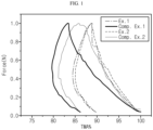
- FIG. 1 shows the results of thermomechanical analysis (TMA) of Examples and Comparative Examples.
- 'A and/or B' means 'A, B or both of them'.
- the electrochemical device is a system in which chemical energy is converted into electrical energy through electrochemical reactions, has a concept including a primary battery and a secondary battery, wherein the secondary battery is capable of charging and discharging and has a concept covering a lithium ion battery, nickel-cadmium battery, nickel-metal hydride battery, or the like.
- the separator according to the present disclosure functions as a porous ion-conducting barrier which allows ions to pass therethrough while interrupting an electrical contact between a negative electrode and a positive electrode.
- the separator has a plurality of pores formed therein, and the pores are interconnected preferably so that gases or liquids may pass from one surface of the substrate to the other surface of the substrate.
- the separator according to the present disclosure includes a porous substrate including a plurality of pores.
- the separator may include a heat resistant layer formed on at least one surface of the porous substrate, if necessary.
- the porous substrate includes a polymer material and the heat resistant layer includes inorganic particles and a binder resin.
- the porous substrate has a small thickness and high porosity, while satisfying a desired range of compressibility, maximum compressibility and permanent strain.
- the separator including the porous substrate shows excellent voltage resistance and has an effect of reducing generation of a short-circuit.
- the heat resistant layer may have a porous structure formed by the interstitial volumes in the inorganic particles. Such a porous structure provides an effect of improving electrolyte holding capability.
- the heat resistant layer uses inorganic particles having heat-absorbing property so that the compressibility, maximum compressibility and permanent strain may be increased, resulting in improvement of resistance against a short-circuit.
- the heat resistant layer when the separator includes a heat resistant layer, may be present in an amount of 3-40vol% based on 100 vol% of the total volume of the separator. In addition to this or independently from this, the heat resistant layer may have a thickness corresponding to 5-50% based on 100% of the total thickness of the separator.
- the porous substrate includes a polyethylene having a weight-average molecular weight of 300,000 to 500,000 and polypropylene in an amount of 5 wt% or less based on 100 wt% of the porous substrate, the polymers having electrical insulation property with a view to imparting a shut-down function.
- the term 'shut-down function' means a function of preventing thermal runaway of a battery by allowing a polymer resin to be molten so that the pores of the porous substrate may be closed and ion conduction may be interrupted, when the battery temperature is increased.
- the porous substrate may have a thickness of 5-20 ⁇ m in terms of thin filming of an electrochemical device and an increase in energy density.
- the porous substrate has a thickness smaller than the above-defined range, it cannot perform a function as a conducting barrier sufficiently.
- the separator may show excessively increased resistance.
- the porous substrate includes ⁇ high-molecular weight polyethylene (HMWPE)' having a weight average molecular weight (Mw) of 300,000-500,000.
- HMWPE high-molecular weight polyethylene
- the porous substrate made of a polymer material satisfying the above-defined range of thickness may be obtained by using polyethylene through a wet process.
- the porous substrate includes polyethylene, and further includes polypropylene.
- the content of polypropylene is less than 5 wt% based on 100 wt% of the substrate.
- the polymer As the content of polypropylene is increased, the polymer has a lower degree of crystallization, and thus causes no degradation of compressibility or permanent strain even when the porosity is high and the penetration strength is low, and can maintain a low Hi-Pot defect ratio suggesting voltage resistance.
- the content of polypropylene is not within the above-defined range, pores cannot be formed well in the porous substrate during the manufacture thereof through a wet process due to chemical instability, thereby making it difficult to develop porous property.
- the content of polypropylene is controlled suitably within the above-defined range.
- the porous substrate may further include at least one polymer resin, such as polyethylene terephthalate, polybutylene terephthalate, polyacetal, polyamide, polycarbonate, polyimide, polyetheretherketone, polyethersulfone, polyphenylene oxide, polyphenylene sulfide or polyethylene naphthalene, if necessary.
- polymer resin such as polyethylene terephthalate, polybutylene terephthalate, polyacetal, polyamide, polycarbonate, polyimide, polyetheretherketone, polyethersulfone, polyphenylene oxide, polyphenylene sulfide or polyethylene naphthalene, if necessary.
- the porous substrate may be a porous polymer film obtained by the following method, and may be a monolayer film or multilayer film formed by lamination of two sheets of films.
- the porous substrate may have a penetration strength of 450 gf or more with a view to improvement of production yield.
- the penetration strength refers to the maximum penetration load (gf) as determined by carrying out a penetration test by using Instron UTM system under the conditions of a needle tip radius of curvature of 0.5 mm and a penetration rate of 50 mm/sec.
- the porous substrate of the separator has a) a compressibility of 15% or less, when it is pressurized under a force of 1 N at 40°C.
- the porous substrate has b) a maximum compressibility of 18% or less, when it is pressurized under a force of 1 N at 40°C, and c) a permanent strain of 13% or less, when it is pressurized under a force of 1 N at 40°C.
- the compressibility, maximum compressibility and permanent strain may be determined by using an apparatus for thermomechanical analysis (TMA), such as Q400, in a compression mode.
- TMA thermomechanical analysis
- a porous substrate specimen having a predetermined size is prepared, a hemispherical tip is placed on the specimen, and then compressibility, maximum compressibility and permanent strain may be determined, while pressure is increased from 0.04 N to 1 N at a rate of 0.25 N/min at a temperature of 40°C and is decreased from 1 N to 0.04 N at the same rate.
- the volume change (Formula 1) when pressure reaches 1 N is taken as compressibility and the highest volume change (Formula 2) is determined within the total pressure range and taken as the maximum compressibility, and the final volume change (Formula 3) of the specimen recovered after compression is determined and taken as permanent strain.
- the specimen may have a size of 10 mm x 10 mm.
- Each of the volume changes is defined by any one of Formula 1 to Formula 3. In each formula, the difference between the volume of a strained specimen and the initial volume of the specimen is calculated as an absolute value.
- Compressibility (%) (
- / Initail volume of specimen) x 100 Maximum compressibility (%) (
- / Initial volume of specimen) x 100 Permanent strain (%) (
- the separator satisfying the above conditions provides a battery with improved voltage resistance, thereby providing an increased breakdown voltage and a reduced ratio of short-circuit generation (Hi-Pot defect ratio) even under a high-voltage condition.
- ⁇ breakdown voltage' means the highest voltage capable of being endured by an insulator
- 'breakdown' means that an insulator is broken and loses insulation property above a certain value of voltage when applying voltage thereto.
- the voltage resistance may be determined by a method for measuring the breakdown voltage of a separator.
- a voltage, where breakdown occurs may be determined, when a separator as an insulator is disposed between two conductors and voltage is applied thereto.
- the breakdown voltage may be determined by using AC/DC/IR Hi-Pot tester.
- a porous substrate is disposed between an aluminum lower jig and a cylindrical electrode rod, and a DC current of 0.5 mA and a voltage increase of 100 V/s (voltage 3 kV, ramp up time 30 s) are set.
- voltage is increased and determination is stopped when a short-circuit occurs, and then the voltage at that time is defined as ⁇ breakdown voltage'.
- evaluation of a ratio of short-circuit generation is based on a breakdown voltage of 75 V, and refers to a ratio (%) of the number of specimens in which a short-circuit occurs under a condition of 75 V or less based on the total number of tested specimens.
- the ratio (%) of the number of specimens in which a short-circuit occurs at 75 V or less is less than 1% based on the total number of specimens.
- the compressibility and permanent strain may be affected by the penetration strength and porosity of the porous substrate.
- the porous substrate has higher penetration strength and lower porosity, it satisfies the above-defined compressibility and permanent strain conditions.
- the porous substrate may have a porosity controlled adequately within a range of 30-45%.
- the porosity is 45% or less, and may preferably be 40% or less.
- the porosity is controlled to 45% or less in order to realize a desired range of compressibility, such as the condition of a compressibility of 18% or less.
- the term 'porosity' means a ratio of volume occupied by pores based on the total volume of a given structure, is expressed in the unit of %, and may be used interchangeably with the term of pore ratio or porous degree.
- the net density of an electrode active material layer is calculated from the density (apparent density) of a finished electrode (electrode active material layer) and the compositional ratio of ingredients contained in the electrode (electrode active material layer) and density of each ingredient. Then, the porosity of an electrode active material layer may be calculated from the difference between the apparent density and the net density.
- the porous substrate may be formed to have a monolayer structure or a laminate structure of two or more layers, as long as it has the above-described characteristics.
- each layer preferably has the above-described characteristics in terms of materials.
- the laminated structure should satisfy a final thickness of 5-20 ⁇ m.
- the porous substrate may be obtained by a method for forming a polymer film, preferably a wet process.
- the wet process includes the steps of: (S1) preparing a mixture; (S2) forming an extruded sheet; (S3) forming a film; (S4) removing a pore-forming agent; and (S5) carrying out orientation-relaxation of the film.
- step (S1) the selected polymer resins including polyethylene having a weight-average molecular weight of 300,000 - 500,000 and polypropylene are mixed with a pore-forming agent.
- the polymer resin is the same as the polymer resin of a porous substrate as described above.
- the polymer resins include the polyethylene and polypropylene, and may further include polybutylene and/or polypentene.
- the pore-forming agent is a material dispersed in the polymer, imparting heterogeneity to the substrate prepared through extrusion, orientation, or the like, and removed from the substrate subsequently. Therefore, the portion of the substrate, where the pore-forming agent is positioned, is left in the form of pores.
- the pore-forming agent is a material present preferably in a liquid state during extrusion, but may be a material maintaining a solid state.
- the pore-forming agent may include an aliphatic hydrocarbon solvent, such as liquid paraffin, paraffin oil, mineral oil or paraffin wax; vegetable oil, such as soybean oil, sunflower oil, rapeseed oil, palm oil, coconut oil, corn oil, grape seed oil or cottonseed oil; or a plasticizer, such as dialkyl phthalate.
- the plasticizer may include di-2-ethylhexyl phthalate (DOP), di-butyl-phthalate (DBP), di-isononyl phthalate (DINP), di-isodecyl phthalate (DIDP), butyl benzyl phthalate (BBP), or the like.
- liquid paraffin LP, also referred to as liquid-state paraffin
- LP liquid paraffin
- the content of the pore-forming agent may be controlled adequately in order to realize a desired level of porosity, when manufacturing the separator.
- a higher content of pore-forming agent is preferred considering improvement of air permeability, but an excessive amount of pore-forming agent may adversely affect the strength of the finished substrate. Therefore, the content of the pore-forming agent may be 1-80 wt% based on 100 wt% of the total amount of the polymer resin with the pore-forming agent.
- the content of the pore-forming agent may be controlled to 70 wt% or less, 60 wt% or less, or 50 wt% or less, and 1 wt% or more, 20 wt% or more, or 40 wt% or more, within the above-defined range.
- the pore-forming agent may be used in an amount of 1-60 wt% based on the total weight of the polymer resin with the pore-forming agent in order to realize a suitable level of porosity, i.e., a porosity of 45% or less, of the porous substrate.
- the extruder is not particularly limited and may be an extruder used conventionally in the art.
- Non-limiting examples of the extruder include an extruder equipped with a T-die or tubular die.
- the extrusion process may be carried out at an extrusion temperature used currently, but is carried out preferably at a temperature higher than the melting point of the polymer resin by 10-100°C.
- the extrusion temperature is excessively higher than the above-defined range, it is difficult to form a film due to the thermal degradation of the polymer resin and the mechanical properties of the finished substrate are degraded undesirably.
- Extruded sheets may be obtained through the extrusion process.
- the orientation process is carried out by using a currently used orientation machine.
- the orientation machine that may be used includes a sequential biaxial orientation machine, but is not limited thereto. It is possible to increase the mechanical strength of the porous substrate through the orientation of the extruded sheets.
- the orientation process is carried out in the machine direction (MD, longitudinal direction) and/or transverse direction (TD, vertical direction). Through the orientation in either direction or both directions, it is possible to increase the tensile strength in the corresponding direction.
- the separator according to the present disclosure may be subjected to orientation in ether of the machine direction (MD) and the transverse direction (TD) (e.g. uniaxial orientation), or in both of the machine direction (MD) and the transverse direction (TD) (e.g. biaxial orientation), sequentially or at the same time.
- the pore-forming agent is removed from the resultant product of step (S3).
- the pore-forming agent is removed through extraction using a solvent and drying. After removing the pore-forming agent, the spaces occupied by the pore-forming agent become pores.
- the solvent that may be used for extraction of the pore-forming agent is any solvent capable of extracting the pore-forming agent, but preferably includes a solvent, such as methyl ethyl ketone, methylene chloride or hexane, having high extraction efficiency and a high drying rate.
- the solvent may be methylene chloride, such as methylene dichloride (MC).
- the extraction may be carried out by using any conventional solvent extraction process, such as an immersion process, solvent spray process or ultrasonication process, and such extraction processes may be used alone or in combination.
- a thermal fixing step is carried out. It is possible to obtain a finished separator having desired physical properties, porosity and air permeability through the thermal fixing step.
- the thermal fixing step may be carried out by using a heating system, such as oven, capable of applying temperature suitable for thermal fixing.
- a heating system such as oven
- the film dried from the preceding step is subjected to thermal fixing in order to reduce the shrinkage of the finished film by removing the stress remaining in the film.
- the thermal fixing includes fixing a film and applying heat thereto so that the film to be shrunk may be fixed forcibly and the residual stress may be removed. A higher thermal fixing temperature is preferred in terms of reducing the shrinkage.
- the thermal fixing temperature is selected from such a temperature range that about 10-30 wt% of the crystalline portions of the film may be molten at the temperature.
- the thermal fixing temperature is lower than the temperature where about 10 wt% of the crystalline portions of the film is molten, it is not possible to carry out reorientation of polyethylene molecules in the film sufficiently and to provide an effect of removing the residual stress from the film.
- the thermal fixing temperature is higher than the temperature where about 30 wt% of the crystalline portions of the film is molten, the pores are blocked due to partial melting, resulting in degradation of permeability.
- the porous substrate may have a monolayer structure.
- the porous substrate may be a laminate film formed by lamination of at least two sheets of films.
- at least one film contained in the laminate film may be formed by the above-described method.
- a separator for a secondary battery in order to increase the energy density of the battery.
- a sufficient amount of insulation material cannot be incorporated thereto, thereby causing the problem of degradation of insulation property or mechanical strength.
- the separator may be deformed by the heat and pressure applied during the manufacture of an electrode assembly through stacking of electrodes and separators, thereby causing the problem of a decrease in breakdown voltage.
- a separator which comprises a porous polymer film as a porous substrate for a separator, satisfies a thickness of 5-20 ⁇ m, and satisfies the following conditions a) to c):
- the porous substrate is obtained by the above-described method for manufacturing a porous substrate, includes polyethylene and further includes polypropylene.
- the porous substrate satisfies the following conditions: the content of polyethylene is 80wt% or more, or 90 wt% or more, based on 100 wt% of the porous substrate, and the content of polypropylene is 5 wt% or less, for example, less than 5 wt%.
- the porous substrate satisfies the condition of a porosity of 30-45%.
- the selected porous substrate satisfying the above-mentioned conditions has excellent voltage resistance, and can accomplish a high breakdown voltage and can reduce short-circuit generation (Hi-Pot defect ratio) significantly, when it is applied to the manufacture of a separator. See, the above description with reference to the voltage resistance, breakdown voltage and short-circuit generation.
- the separator may include a heat resistant layer formed on at least one surface of the porous substrate.
- the heat resistant layer includes an adhesive binder resin and inorganic particles, has a plurality of micropores therein, wherein the micropores are interconnected, and shows structural characteristics as a porous layer so that gases or liquids may permeate from one surface to the other surface.
- the heat resistant layer may include the binder resin and the inorganic particles at a weight ratio of 1:99-30:70. The ratio may be controlled adequately within the above-defined range.
- the binder resin may be used in an amount of 1 wt% or more, 5 wt% or more, or 10 wt% or more
- the inorganic particles may be used in an amount of 80 wt% or more, 85 wt% or more, 90 wt% or more, or 95 wt% or more, based on 100 wt% of the total amount of the binder resin with the inorganic particles.
- the heat resistant layer preferably has a porous structure with a view to ion permeability.
- the heat resistant layer may be formed by binding the inorganic particles by means of the binder resin, wherein pores are formed by the interstitial volume among the inorganic particles.
- the interstitial volume is a space defined by the inorganic particles facing each other substantially in a closely packed or densely packed structure of the inorganic particles.
- the heat resistant layer may have a porosity of 30-70 vol%.
- the porosity may be 35 vol% or more, or 40 vol% or more.
- the porosity may be 65 vol% or less, or 60 vol% or less.
- the porosity may be 40-60 vol%.
- the porosity is 70 vol% or less, it is possible to ensure dynamic property with which a pressing process for adhesion with an electrode can be tolerated, and to prevent an excessive increase in surface opening, thereby facilitating adhesion.
- the porosity is 30 vol% or more, it is possible to provide preferred ion permeability.
- the porosity may be determined by using BELSORP (BET system) available from BEL JAPAN Co., or mercury intrusion porosimetry.
- BELSORP BET system
- the net density of an electrode active material layer is calculated from the density (apparent density) of a finished electrode (electrode active material layer) and the compositional ratio of ingredients contained in the electrode (electrode active material layer) and density of each ingredient. Then, the porosity of an electrode active material layer may be calculated from the difference between the apparent density and the net density.
- the heat resistant layer may have a thickness of 1-6 ⁇ m on one side of the porous substrate.
- the heat resistant layer may have a thickness of 2 ⁇ m or more, or 3 ⁇ m or more, if necessary.
- the thickness is preferably 4 ⁇ m or less, and more preferably 3 ⁇ m or less.
- the separator provided with the heat resistant layer may satisfy at least one of the following conditions a'), b') and c'):
- the compressibility, maximum compressibility and permanent strain of the separator may be determined according to the above-described method for determining of the compressibility, maximum compressibility and permanent strain of the porous substrate.
- non-limiting examples of the binder resin that may be used for the heat resistant layer include any one polymer resin selected from the group consisting of polyvinylidene fluoride-co-hexafluoropropylene, polyvinylidene fluoride-co-trichloroethylene, polymethylmethacrylate, polybutylacrylate, polyacrylonitrile, polyvinylpyrrolidone, polyvinylacetate, polyethylene-co-vinyl acetate, polyethylene oxide, polyarylate, cyanoethylpullulan, cyanoethylpolyvinylalchol, cyanoethylcellulose, cyanoethyl sucrose, pullulan and carboxy methyl cellulose, or a mixture of two or more of them.
- the scope of the present disclosure is not limited thereto.
- the inorganic particles that may be used for the heat resistant layer are not particularly limited, as long as they are electrochemically stable.
- the inorganic particles are not particularly limited, as long as they cause no oxidation and/or reduction in the operating voltage range (e.g. 0-5V based on Li/Li + ) of an applicable electrochemical device.
- the inorganic particles having a high dielectric constant they contribute to an increase in dissociation degree of the electrolyte salt, particularly lithium salt, in a liquid electrolyte, and thus can improve ion conductivity of the electrolyte.
- the inorganic particles may include high-dielectric constant inorganic particles having a dielectric constant of 5 or more, preferably 10 or more.
- Non-limiting examples of the inorganic particles having a dielectric constant of 5 or more may include BaTiO 3 , Pb(ZrTi)O 3 (PZT), Pb 1-x La x Zr 1-y Ti y O 3 (PLZT, wherein 0 ⁇ x ⁇ 1, 0 ⁇ y ⁇ 1), Pb(Mg 1/3 Nb 2/3 )O 3 -PbTiO 3 (PMN-PT), hafnia (HfO 2 ), SrTiO 3 , SnO 2 , CeO 2 , MgO, Mg(OH) 2 , NiO, CaO, ZnO, ZrO 2 , SiO 2 , Y 2 O 3 , Al 2 O 3 , SiC, Al(OH) 3 , TiO 2 , or mixtures thereof.
- the inorganic particles that may be used for the heat resistant layer may be inorganic particles capable of transporting lithium ions, i.e. inorganic particles containing lithium elements, not storing lithium therein but transporting lithium ions.
- the inorganic particles capable of transporting lithium ions include lithium phosphate (Li 3 PO 4 ), lithium titanium phosphate (Li x Ti y (PO 4 ) 3 , 0 ⁇ x ⁇ 2, 0 ⁇ y ⁇ 3), lithium aluminum titanium phosphate (Li x Al y Ti z (PO 4 ) 3 , 0 ⁇ x ⁇ 2, 0 ⁇ y ⁇ 1, 0 ⁇ z ⁇ 3), (LiAlTiP) x O y -based glass (1 ⁇ x ⁇ 4, 0 ⁇ y ⁇ 13), such as 14Li 2 O-9Al 2 O 3 -38TiO 2 -39P 2 O 5 , lithium lanthanum titanate (L
- the heat resistant layer may include a heat-absorbing material as inorganic particles.
- the heat-absorbing material is less affected by the temperature applied during the formation of the heat resistant layer or lamination (e.g. hot pressing) of the separator with an electrode, and thus can prevent degradation of the compressibility of the separator.
- the heat-absorbing material include oxides and/or hydroxides containing at least one element selected from the group consisting of aluminum, magnesium, silicon, zirconium, calcium, strontium, barium, antimony, tin, zinc and rare earth elements, but are not limited thereto.
- the metal oxides include alumina, aluminum peroxide, tin-zinc oxides (Zn 2 SnO 4 , ZnSnO 3 ), antimony trioxide (Sb 2 O 3 ), antimony tetraoxide (Sb 2 O 4 ), antimony pentaoxide (Sb 2 O 5 ), or the like.
- the metal hydroxides include aluminum hydroxide (Al(OH) 3 ), magnesium hydroxide (Mg(OH) 2 ), zinc tin hydroxide (ZnSn(OH) 6 ), or the like.
- metal hydroxide a type of metal hydroxide, is decomposed into Al 2 O 3 and water (H 2 O) by absorbing heat at a temperature of 200°C or higher.
- aluminum hydroxide absorbs a heat energy of about 1,000 J/g.
- magnesium hydroxide absorbs a heat energy of about 1,300 J/g. Therefore, metal hydroxide can assist an effect of preventing the shrinkage of a separator through endothermic reaction, as soon as heat corresponding to the above-mentioned heat energy is generated in an electrochemical device.
- the inorganic particles preferably have an average particle diameter of 0.3-1 ⁇ m for the purpose of formation of a coating layer having a uniform thickness and adequate porosity.
- the inorganic particles may have low dispersibility in slurry prepared for preparing the heat resistant layer.
- the coating layer to be formed may have an increased thickness.
- the heat resistant layer may be formed by the method as described hereinafter.
- a binder resin is dissolved in a suitable organic solvent to prepare a polymer solution.
- the solvent preferably has a solubility parameter similar to the solubility parameter of the binder polymer to be used and has a low boiling point. This is because such a solvent facilitates homogeneous mixing and the subsequent solvent removal.
- Non-limiting examples of the solvent that may be used include acetone, tetrahydrofuran, methylene chloride, chloroform, dimethyl formamide, N-methyl-2-pyrrolidone, cyclohexane, water, or a mixture thereof.
- the ratio of the inorganic particles to the binder resin is the same as described above and may be controlled adequately considering the thickness, pore size and porosity of the finished heat resistant layer.
- the inorganic particle slurry is applied to at least one surface of the separator, followed by drying.
- any conventional coating method known in the art may be used.
- various methods, such as dip coating, die coating, roll coating, comma coating or a combination thereof may be used.
- temperature and time conditions may be set adequately so that generation of surface defects on the surface of the composite porous layer may be minimized.
- a drying-aid system such as a drying oven or hot air, may be used within a suitable range.
- the separator according to the present disclosure may be obtained by preparing a heat resistant layer and a porous substrate separately, stacking the sheets, and forming a composite by hot pressing or adhesive.
- Methods for preparing the heat resistant layer as an independent sheet include a method including applying the slurry onto a release sheet, forming the heat resistant layer in the same manner as described above and removing only the heat resistant layer.
- the battery includes a negative electrode, a positive electrode and a separator interposed between the negative electrode and the positive electrode, wherein the separator is the low-resistance separator having the above-mentioned characteristics.
- the positive electrode includes a positive electrode current collector, and a positive electrode active material layer formed on at least one surface of the current collector and containing a positive electrode active material, a conductive material and a binder resin.
- the positive electrode active material may include any one selected from: layered compounds, such as lithium manganese composite oxide (LiMn 2 O 4 , LiMnO 2 , etc.), lithium cobalt oxide (LiCoO 2 ) and lithium nickel oxide (LiNiO 2 ), or those compounds substituted with one or more transition metals; lithium manganese oxides such as those represented by the chemical formula of Li 1+x Mn 2-x O 4 (wherein x is 0-0.33), LiMnO 3 , LiMn 2 O 3 and LiMnO 2 ; lithium copper oxide (Li 2 CuO 2 ); vanadium oxides such as LiVsOs, LiV 3 O 4 , V 2 O 5 or Cu 2 V 2 O 7 ; Ni-site type lithium nickel oxides represented by the chemical formula
- the negative electrode includes a negative electrode current collector, and a negative electrode active material layer formed on at least one surface of the current collector and containing a negative electrode active material, a conductive material and a binder resin.
- the negative electrode may include, as a negative electrode active material, any one selected from: lithium metal oxide; carbon such as non-graphitizable carbon or graphite-based carbon; metal composite oxides, such as Li x Fe 2 O 3 (0 ⁇ x ⁇ 1), Li x WO 2 (0 ⁇ x ⁇ 1), Sn x Me 1-x Me' y O z (Me: Mn, Fe, Pb, Ge; Me': Al, B, P, Si, elements of Group 1, 2 or 3 in the Periodic Table, halogen; 0 ⁇ x ⁇ 1; 1 ⁇ y ⁇ 3; 1 ⁇ z ⁇ 8); lithium metal; lithium alloy; silicon-based alloy; tin-based alloy; metal oxides, such as AuO, SnO 2 , P
- the conductive material may be any one selected from the group consisting of graphite, carbon black, carbon fibers or metal fibers, metal powder, conductive whiskers, conductive metal oxides, activated carbon and polyphenylene derivatives, or a mixture of two or more of such conductive materials. More particularly, the conductive material may be any one selected from natural graphite, artificial graphite, Super-P, acetylene black, Ketjen black, channel black, furnace black, lamp black, thermal black, denka black, aluminum powder, nickel powder, zinc oxide, potassium titanate and titanium dioxide, or a mixture of two or more such conductive materials.
- the current collector is not particularly limited, as long as it causes no chemical change in the corresponding battery and has high conductivity.
- Particular examples of the current collector may include stainless steel, copper, aluminum, nickel, titanium, baked carbon, aluminum or stainless steel surface-treated with carbon, nickel, titanium or silver, or the like.
- the binder resin may be a polymer used currently for an electrode in the art.
- Non-limiting examples of the binder resin include, but are not limited to: polyvinylidene fluoride-co-hexafluoropropylene, polyvinylidene fluoride-co-trichloroethylene, polymethyl methacrylate, polyethylhexyl acrylate, polybutyl acrylate, polyacrylonitrile, polyviny1 pyrro1idone, polyvinyl acetate, polyethylene-co-vinyl acetate, polyethylene oxide, polyarylate, cellulose acetate, cellulose acetate butyrate, cellulose acetatepropionate, cyanoethylpullulan, cyanoethy1polyvinyla1cho1, cyanoethylcellulose, cyanoethylsucrose, pullulan, and carboxymethyl cellulose.
- the electrode assembly prepared as described above may be introduced to a suitable casing and an electrolyte may be injected thereto to obtain a battery.
- the electrolyte is a salt having a structure of A + B - , wherein A + includes an alkali metal cation such as Li + , Na + , K + or a combination thereof, and B - includes an anion such as PF 6 - , BF 4 - , Cl - , Br - , I - , ClO 4 - , AsF 6 - , CH 3 CO 2 - , CF 3 SO 3 - , N(CF 3 SO 2 ) 2 - , C(CF 2 SO 2 ) 3 - or a combination thereof, the salt being dissolved or dissociated in an organic solvent selected from propylene carbonate (PC), ethylene carbonate (EC), diethyl carbonate (DEC), dimethyl carbonate (DMC), dipropyl carbonate (DPC), dimethyl sulfoxide, acetonitrile, dimethoxyethane, diethoxyethane, tetrahydrofuran,
- PC propy
- the present disclosure provides a battery module which includes a battery including the electrode assembly as a unit cell, a battery pack including the battery module, and a device including the battery pack as an electric power source.
- a battery module which includes a battery including the electrode assembly as a unit cell, a battery pack including the battery module, and a device including the battery pack as an electric power source.
- the device include, but are not limited to: power tools driven by the power of an electric motor; electric cars, including electric vehicles (EV), hybrid electric vehicles (HEV), plug-in hybrid electric vehicles (PHEV), or the like; electric two-wheeled vehicles, including E-bikes and E-scooters; electric golf carts; electric power storage systems; or the like.
- porosity may be determined based on ASTM D-2873.
- Gurley values can be determined by using Gurley type Densometer (No. 158) available from Toyoseiki Co., according to the method of Japanese Industrial Standard Gurley (JIS Gurley).
- JIS Gurley Japanese Industrial Standard Gurley
- the Gurley value means a time (second) required for 100 cc of air to pass through a porous substrate or separator having a size of 1 in 2 under a constant air pressure of 4.8 inches.
- the tensile strength of each of the porous substrates according to Examples and Comparative Examples can be determined by mounting each porous substrate to a UTM (tensile strength tester) and drawing it in MD (machine direction) and TD (transverse direction).
- the average particle diameter of inorganic particles means the particle size (D 50 ) of 50% of the integrated value from a smaller particle diameter calculated based on the results of measurement of particle size distribution of the particles after the classification thereof using a conventional particle size distribution measuring system.
- D 50 particle size of 50% of the integrated value from a smaller particle diameter calculated based on the results of measurement of particle size distribution of the particles after the classification thereof using a conventional particle size distribution measuring system.
- particle size distribution can be determined by after dispersing the inorganic particles sufficiently in aqueous solution, followed by agitation with an ultrasonic dispersing device, by using a suitable laser diffraction or scattering type particle size distribution measuring system.
- Measurement of the BET specific surface area of inorganic particles may be carried out by the Brunauer-Emmett-Teller (BET) method.
- BET Brunauer-Emmett-Teller
- a porosimetry analyzer Bell Japan Inc., Belsorp-II mini
- nitrogen gas adsorption flowmetry may be used to determine the specific surface area by the BET 6-dot method through nitrogen gas adsorption flowmetry.
- High-density polyethylene and polypropylene were prepared, and liquid paraffin oil having a dynamic viscosity of 40 cSt at 40°C was used as a diluent.
- high-density polyethylene and liquid paraffin oil were prepared at a weight ratio of 35:65.
- the weight average molecular weight of high-density polyethylene and content of polypropylene based on 100 wt% of the porous substrate are described in the following Table 1.
- the ingredients were introduced to a biaxial extruder and kneaded therein to provide a polyethylene solution and extrusion was carried out at a temperature of 135°C.
- Example 1 Comp. Ex. 1
- Example 2 Comp. Ex. 2 Weight average molecular weight (Mw) 370,000 350,000 370,000 280,000 Content of polypropylene (wt%, content of polypropylene based on 100 wt% of porous substrate) 4.8wt% 0wt% 4.
- Example 1 shows lower porosity, higher Gurley value to provide higher penetration strength or tensile strength.
- Example 1 shows higher compressibility, maximum compressibility and permanent strain. Therefore, it can be seen that the compressibility, maximum compressibility and permanent strain are affected by mechanical properties, such as penetration strength or tensile strength.
- Example 2 and Comparative Example 2 show a similar porosity value but Example 2 shows higher penetration strength or tensile strength.
- Example 2 shows higher compressibility, maximum compressibility and permanent strain. Therefore, it can be also seen from Example 2 and Comparative Example 2 that the compressibility, maximum compressibility and permanent strain are affected by mechanical properties, such as penetration strength or tensile strength.
- the porosity or Gurley value is less related with the compressibility, maximum compressibility and permanent strain. Therefore, it can be seen that it is difficult to control mechanical properties by adjusting porosity or Gurley value, and porosity or Gurley value is not sufficient as grounds of judging mechanical properties.
- FIG. 1 shows the thermomechanical analysis (TMA) results of each of the porous substrates according to Examples and Comparative Examples. It can be seen that the porous substrates according to Examples show a smaller volume change as compared to Comparative Examples.
- PVdF-HFP polyvinylidene fluoride-co-hexafluoropropylene
- Example 3 shows better results in terms of compressibility, maximum compressibility and permanent strain.
- Example 3 shows higher voltage resistance as compared to Example 4. Therefore, it can be seen that the type of inorganic particles may affect the voltage resistance, in the case of a separator having a heat resistant layer.
- the compressibility, maximum compressibility and permanent strain were determined in the same manner as Example 1.
Landscapes
- Chemical & Material Sciences (AREA)
- Chemical Kinetics & Catalysis (AREA)
- Electrochemistry (AREA)
- General Chemical & Material Sciences (AREA)
- Engineering & Computer Science (AREA)
- Power Engineering (AREA)
- Manufacturing & Machinery (AREA)
- Inorganic Chemistry (AREA)
- Materials Engineering (AREA)
- Microelectronics & Electronic Packaging (AREA)
- Composite Materials (AREA)
- Health & Medical Sciences (AREA)
- Medicinal Chemistry (AREA)
- Polymers & Plastics (AREA)
- Organic Chemistry (AREA)
- Cell Separators (AREA)
- Electric Double-Layer Capacitors Or The Like (AREA)
Claims (6)
- Separator für eine elektrochemische Vorrichtung, der ein poröses Substrat umfasst, worin das poröse Substrat Polyethylen und Polypropylen umfasst, das poröse Substrat die folgenden Bedingungen a) - c) erfüllt, wenn es bei 40°C von 0,04 N bis 1 N mit einer Geschwindigkeit von 0,25 N/min unter Druck gesetzt wird und der Druck von 1 N bis 0,04 N in der gleichen Geschwindigkeit gelöst wird: a) die Kompressibilität beträgt 15 % oder weniger, wenn der Druck 1 N erreicht, b) die maximale Kompressibilität beträgt 18 % oder weniger innerhalb des vorstehend definierten Druckbereichs, und c) die verbleibende Verformung beträgt 15 % oder weniger, wobei das poröse Substrat eine Porosität von 45 % oder weniger aufweist, bestimmt in Übereinstimmung mit ASTM D-2873; und das Polyethylen ein gewichtsgemitteltes Molekulargewicht (Mw) von 3000.000-500.000 aufweist, worin das poröse Substrat Polypropylen in einer Menge von weniger als 5 Gew.-% umfasst, bezogen auf 100 Gew.-% des porösen Substrats.
- Separator für eine elektrochemische Vorrichtung gemäß Anspruch 1, worin das poröse Substrat eine Dicke von 5-20 µm aufweist.
- Separator für eine elektrochemische Vorrichtung gemäß Anspruch 1, worin das poröse Substrat eine Porosität von 45 % oder weniger, bestimmt gemäß ASTM D-2873, und eine Kompressibilität von 15 % oder weniger aufweist.
- Separator für eine elektrochemische Vorrichtung gemäß Anspruch 1, worin das poröse Substrat Poren aufweist, die durch das Entfernen eines Porenbildners aus einer Mischung eines Polymerharzes mit dem Porenbildner gebildet sind.
- Separator für eine elektrochemische Vorrichtung gemäß Anspruch 1, der eine wärmebeständige Schicht umfasst, die auf zumindest einer Oberfläche des porösen Substrats angeordnet ist, worin die wärmebeständige Schicht ein Bindeharz mit anorganischen Partikeln umfasst und die anorganischen Partikel ein Oxid, Hydroxid oder beides umfassen und das Oxid und Hydroxid zumindest ein Element umfassen, das ausgewählt aus der Gruppe bestehend aus Aluminium, Magnesium, Silicium, Zirkonium, Calcium, Strontium, Barium, Antimon, Zinn, Zink und Seltenerdelementen.
- Separator für eine elektrochemische Vorrichtung gemäß Anspruch 1, der zumindest eine wärmebeständige umfasst, die auf zumindest einer Oberfläche des porösen Substrats angeordnet ist, und der zumindest eine der Bedingungen von einer Kompressibilität von 15 % oder weniger, einer maximalen Kompressibilität von 17 % oder weniger und einer verbleibenden Verformung von 13 % erfüllt.
Priority Applications (1)
| Application Number | Priority Date | Filing Date | Title |
|---|---|---|---|
| EP24181073.8A EP4404367B1 (de) | 2018-06-22 | 2019-06-21 | Separator für elektrochemische vorrichtung und elektrochemische vorrichtung damit |
Applications Claiming Priority (2)
| Application Number | Priority Date | Filing Date | Title |
|---|---|---|---|
| KR20180072384 | 2018-06-22 | ||
| PCT/KR2019/007555 WO2019245346A1 (ko) | 2018-06-22 | 2019-06-21 | 전기화학소자용 분리막 및 이를 포함하는 전기화학소자 |
Related Child Applications (2)
| Application Number | Title | Priority Date | Filing Date |
|---|---|---|---|
| EP24181073.8A Division EP4404367B1 (de) | 2018-06-22 | 2019-06-21 | Separator für elektrochemische vorrichtung und elektrochemische vorrichtung damit |
| EP24181073.8A Division-Into EP4404367B1 (de) | 2018-06-22 | 2019-06-21 | Separator für elektrochemische vorrichtung und elektrochemische vorrichtung damit |
Publications (3)
| Publication Number | Publication Date |
|---|---|
| EP3787067A1 EP3787067A1 (de) | 2021-03-03 |
| EP3787067A4 EP3787067A4 (de) | 2021-06-09 |
| EP3787067B1 true EP3787067B1 (de) | 2024-08-07 |
Family
ID=68982647
Family Applications (2)
| Application Number | Title | Priority Date | Filing Date |
|---|---|---|---|
| EP19822265.5A Active EP3787067B1 (de) | 2018-06-22 | 2019-06-21 | Separator für elektrochemische vorrichtung und elektrochemische vorrichtung mit diesem separator |
| EP24181073.8A Active EP4404367B1 (de) | 2018-06-22 | 2019-06-21 | Separator für elektrochemische vorrichtung und elektrochemische vorrichtung damit |
Family Applications After (1)
| Application Number | Title | Priority Date | Filing Date |
|---|---|---|---|
| EP24181073.8A Active EP4404367B1 (de) | 2018-06-22 | 2019-06-21 | Separator für elektrochemische vorrichtung und elektrochemische vorrichtung damit |
Country Status (8)
| Country | Link |
|---|---|
| US (2) | US12002986B2 (de) |
| EP (2) | EP3787067B1 (de) |
| KR (1) | KR102392398B1 (de) |
| CN (1) | CN111801811B (de) |
| ES (1) | ES2986423T3 (de) |
| HU (1) | HUE067892T2 (de) |
| PL (1) | PL3787067T3 (de) |
| WO (1) | WO2019245346A1 (de) |
Families Citing this family (4)
| Publication number | Priority date | Publication date | Assignee | Title |
|---|---|---|---|---|
| EP4231432A4 (de) * | 2021-05-07 | 2025-06-25 | LG Energy Solution, Ltd. | Poröses substrat für separator und separator für elektrochemische vorrichtung damit |
| KR102566179B1 (ko) * | 2022-02-23 | 2023-08-11 | 주식회사 엘지에너지솔루션 | 전기화학소자용 분리막 기재, 상기 기재를 포함하는 분리막 및 전지 셀 분리막 형성방법 |
| EP4411962A4 (de) | 2022-06-14 | 2025-10-22 | Lg Energy Solution Ltd | Polyolefinseparator für elektrochemische vorrichtung und elektrochemische vorrichtung damit |
| KR20250128420A (ko) * | 2024-02-20 | 2025-08-28 | 더블유스코프코리아 주식회사 | 용매 조성물 및 이를 이용한 다공성 필름의 제조방법 |
Family Cites Families (30)
| Publication number | Priority date | Publication date | Assignee | Title |
|---|---|---|---|---|
| JP2883726B2 (ja) | 1990-11-14 | 1999-04-19 | 日東電工株式会社 | 電池用セパレータの製造法 |
| US5281491A (en) | 1991-12-20 | 1994-01-25 | W. R. Grace & Co. | Battery separator |
| US5240655A (en) | 1991-12-20 | 1993-08-31 | W. R. Grace & Co.-Conn. | Process of making a battery separator |
| US6080507A (en) | 1998-04-13 | 2000-06-27 | Celgard Inc. | Trilayer battery separator |
| JPH11329290A (ja) | 1998-05-13 | 1999-11-30 | Toshiba Corp | 陰極線管用電子銃およびその組立方法 |
| JP4931163B2 (ja) | 2001-04-24 | 2012-05-16 | 旭化成イーマテリアルズ株式会社 | ポリオレフィン製微多孔膜 |
| WO2006134684A1 (ja) * | 2005-06-15 | 2006-12-21 | Matsushita Electric Industrial Co., Ltd. | リチウム二次電池 |
| KR100943236B1 (ko) * | 2006-02-14 | 2010-02-18 | 에스케이에너지 주식회사 | 용융파단 특성이 우수한 폴리올레핀 미세다공막 및 그제조방법 |
| JP5202816B2 (ja) * | 2006-04-07 | 2013-06-05 | 東レバッテリーセパレータフィルム株式会社 | ポリオレフィン微多孔膜及びその製造方法 |
| KR100995074B1 (ko) | 2007-12-11 | 2010-11-18 | 삼성에스디아이 주식회사 | 비수계 리튬 이차전지용 세퍼레이터 및 이를 포함하는 비수계 리튬 이차전지 |
| KR100947072B1 (ko) | 2008-03-27 | 2010-04-01 | 삼성에스디아이 주식회사 | 전극조립체 및 이를 구비하는 이차전지 |
| EP2111912A1 (de) * | 2008-04-24 | 2009-10-28 | Tonen Chemical Corporation | Mikroporöse Polyolefinmembran und Herstellungsverfahren dafür |
| JP4846882B2 (ja) * | 2009-08-25 | 2011-12-28 | 旭化成イーマテリアルズ株式会社 | 微多孔膜捲回体及びその製造方法 |
| KR101336593B1 (ko) * | 2010-04-20 | 2013-12-05 | 에스케이이노베이션 주식회사 | 생산성이 우수하며 물성조절이 용이한 폴리올레핀계 미세다공막 제조방법 |
| CN103035864B (zh) * | 2011-09-30 | 2017-06-06 | 天津东皋膜技术有限公司 | 具有压缩弹性热关断耐高温的涂层隔膜 |
| KR101330675B1 (ko) * | 2011-11-29 | 2013-11-18 | 더블유스코프코리아 주식회사 | 이차전지용 코팅 분리막 및 그 제조방법 |
| WO2013125906A1 (ko) | 2012-02-24 | 2013-08-29 | 성균관대학교 산학협력단 | 내열성이 향상된 세퍼레이터 및 이를 구비한 전기화학소자 |
| HUE052426T2 (hu) | 2012-03-28 | 2021-04-28 | Asahi Chemical Ind | Porózus film és többrétegû porózus film |
| US10559802B2 (en) | 2012-08-07 | 2020-02-11 | Celgard, Llc | Separator membranes for lithium ion batteries and related methods |
| CN105917494B (zh) * | 2014-01-10 | 2018-12-07 | 东丽株式会社 | 电池用隔膜及其制造方法 |
| KR102320739B1 (ko) * | 2014-06-20 | 2021-11-01 | 도레이 카부시키가이샤 | 폴리올레핀 미세 다공질 막, 전지용 세퍼레이터 및 전지 |
| KR101962418B1 (ko) | 2014-06-24 | 2019-03-27 | 제일모직 주식회사 | 분리막, 이의 제조방법 및 이를 이용한 전지 |
| KR20160002447A (ko) | 2014-06-30 | 2016-01-08 | 제일모직주식회사 | 다공성 폴리올레핀계 분리막 및 이의 제조 방법 |
| KR101924988B1 (ko) * | 2015-04-30 | 2018-12-04 | 주식회사 엘지화학 | 전기화학소자용 분리막의 제조방법 |
| JP6334464B2 (ja) * | 2015-06-16 | 2018-05-30 | マクセルホールディングス株式会社 | 扁平形非水二次電池の製造方法 |
| JP7047382B2 (ja) * | 2016-08-29 | 2022-04-05 | 東レ株式会社 | ポリオレフィン微多孔膜、リチウムイオン二次電池及びポリオレフィン微多孔膜製造方法 |
| EP3429015B1 (de) * | 2016-10-07 | 2023-11-01 | LG Energy Solution, Ltd. | Trennschicht für lithium-ionen-sekundärbatterie sowie lithium-ionen-sekundärbatterie damit |
| KR101958835B1 (ko) * | 2016-10-26 | 2019-07-02 | 제일모직 주식회사 | 분리막, 이의 제조방법 및 이를 이용한 전지 |
| KR102028062B1 (ko) | 2016-12-21 | 2019-10-02 | 주식회사 경동전자 | 저발열 밸브 구동기 |
| CN111512472A (zh) * | 2017-11-03 | 2020-08-07 | 赛尔格有限责任公司 | 改进的微孔膜、电池隔板、电池、和具有它们的装置 |
-
2019
- 2019-06-21 EP EP19822265.5A patent/EP3787067B1/de active Active
- 2019-06-21 CN CN201980016942.XA patent/CN111801811B/zh active Active
- 2019-06-21 PL PL19822265.5T patent/PL3787067T3/pl unknown
- 2019-06-21 EP EP24181073.8A patent/EP4404367B1/de active Active
- 2019-06-21 KR KR1020190074411A patent/KR102392398B1/ko active Active
- 2019-06-21 US US16/979,816 patent/US12002986B2/en active Active
- 2019-06-21 HU HUE19822265A patent/HUE067892T2/hu unknown
- 2019-06-21 WO PCT/KR2019/007555 patent/WO2019245346A1/ko not_active Ceased
- 2019-06-21 ES ES19822265T patent/ES2986423T3/es active Active
-
2024
- 2024-04-26 US US18/647,532 patent/US20240283088A1/en active Pending
Also Published As
| Publication number | Publication date |
|---|---|
| KR102392398B1 (ko) | 2022-04-29 |
| EP3787067A1 (de) | 2021-03-03 |
| US20240283088A1 (en) | 2024-08-22 |
| KR20200000372A (ko) | 2020-01-02 |
| EP3787067A4 (de) | 2021-06-09 |
| CN111801811A (zh) | 2020-10-20 |
| PL3787067T3 (pl) | 2024-10-21 |
| US12002986B2 (en) | 2024-06-04 |
| WO2019245346A1 (ko) | 2019-12-26 |
| EP4404367A3 (de) | 2024-08-07 |
| CN111801811B (zh) | 2022-11-01 |
| HUE067892T2 (hu) | 2024-11-28 |
| EP4404367B1 (de) | 2025-11-05 |
| US20210050575A1 (en) | 2021-02-18 |
| ES2986423T3 (es) | 2024-11-11 |
| EP4404367A2 (de) | 2024-07-24 |
Similar Documents
| Publication | Publication Date | Title |
|---|---|---|
| US20250343322A1 (en) | Separator including polyethylene with highly entangled polymer chains, and electrochemical device including the same | |
| KR100727248B1 (ko) | 다공성 활성층이 코팅된 유기/무기 복합 분리막 및 이를구비한 전기화학소자 | |
| US20240283088A1 (en) | Thin polyethylene separator with reduced compressibility and electrochemical device including the same | |
| EP4231432A1 (de) | Poröses substrat für separator und separator für elektrochemische vorrichtung damit | |
| US12199306B2 (en) | Separator for electrochemical device and electrochemical device comprising same | |
| KR20220029513A (ko) | 전기화학소자용 분리막 및 이를 포함하는 전기화학소자 | |
| US20250260125A1 (en) | Substrate for separator of electrochemical device, separator including same, and method of forming battery cell separator | |
| KR102685396B1 (ko) | 내압축성이 개선된 전기화학소자용 분리막, 이를 포함하는 전기화학소자 및 이를 제조하는 방법 | |
| EP4322307B1 (de) | Separator für eine elektrochemische vorrichtung und elektrochemische vorrichtung damit | |
| US20250158135A1 (en) | Separator for electrochemical devices and electrochemical device comprising same |
Legal Events
| Date | Code | Title | Description |
|---|---|---|---|
| STAA | Information on the status of an ep patent application or granted ep patent |
Free format text: STATUS: THE INTERNATIONAL PUBLICATION HAS BEEN MADE |
|
| PUAI | Public reference made under article 153(3) epc to a published international application that has entered the european phase |
Free format text: ORIGINAL CODE: 0009012 |
|
| STAA | Information on the status of an ep patent application or granted ep patent |
Free format text: STATUS: REQUEST FOR EXAMINATION WAS MADE |
|
| 17P | Request for examination filed |
Effective date: 20201125 |
|
| AK | Designated contracting states |
Kind code of ref document: A1 Designated state(s): AL AT BE BG CH CY CZ DE DK EE ES FI FR GB GR HR HU IE IS IT LI LT LU LV MC MK MT NL NO PL PT RO RS SE SI SK SM TR |
|
| AX | Request for extension of the european patent |
Extension state: BA ME |
|
| REG | Reference to a national code |
Ref country code: DE Ref legal event code: R079 Free format text: PREVIOUS MAIN CLASS: H01M0002160000 Ipc: H01M0050489000 Ref document number: 602019056688 Country of ref document: DE |
|
| A4 | Supplementary search report drawn up and despatched |
Effective date: 20210511 |
|
| RIC1 | Information provided on ipc code assigned before grant |
Ipc: H01M 50/489 20210101AFI20210504BHEP Ipc: H01M 10/052 20100101ALI20210504BHEP Ipc: H01G 11/52 20130101ALI20210504BHEP Ipc: H01M 50/403 20210101ALI20210504BHEP Ipc: H01M 50/417 20210101ALI20210504BHEP Ipc: H01M 50/446 20210101ALI20210504BHEP Ipc: H01M 50/451 20210101ALI20210504BHEP Ipc: H01M 50/457 20210101ALI20210504BHEP Ipc: H01M 50/491 20210101ALI20210504BHEP |
|
| DAV | Request for validation of the european patent (deleted) | ||
| DAX | Request for extension of the european patent (deleted) | ||
| RAP1 | Party data changed (applicant data changed or rights of an application transferred) |
Owner name: LG ENERGY SOLUTION LTD. |
|
| RAP3 | Party data changed (applicant data changed or rights of an application transferred) |
Owner name: LG ENERGY SOLUTION, LTD. |
|
| STAA | Information on the status of an ep patent application or granted ep patent |
Free format text: STATUS: EXAMINATION IS IN PROGRESS |
|
| 17Q | First examination report despatched |
Effective date: 20230911 |
|
| GRAP | Despatch of communication of intention to grant a patent |
Free format text: ORIGINAL CODE: EPIDOSNIGR1 |
|
| STAA | Information on the status of an ep patent application or granted ep patent |
Free format text: STATUS: GRANT OF PATENT IS INTENDED |
|
| RIC1 | Information provided on ipc code assigned before grant |
Ipc: H01M 50/443 20210101ALI20240227BHEP Ipc: H01M 50/409 20210101ALI20240227BHEP Ipc: H01G 9/02 20060101ALI20240227BHEP Ipc: H01M 50/491 20210101ALI20240227BHEP Ipc: H01M 50/457 20210101ALI20240227BHEP Ipc: H01M 50/451 20210101ALI20240227BHEP Ipc: H01M 50/446 20210101ALI20240227BHEP Ipc: H01M 50/417 20210101ALI20240227BHEP Ipc: H01M 50/403 20210101ALI20240227BHEP Ipc: H01G 11/52 20130101ALI20240227BHEP Ipc: H01M 10/052 20100101ALI20240227BHEP Ipc: H01M 50/489 20210101AFI20240227BHEP |
|
| INTG | Intention to grant announced |
Effective date: 20240314 |
|
| GRAS | Grant fee paid |
Free format text: ORIGINAL CODE: EPIDOSNIGR3 |
|
| GRAA | (expected) grant |
Free format text: ORIGINAL CODE: 0009210 |
|
| STAA | Information on the status of an ep patent application or granted ep patent |
Free format text: STATUS: THE PATENT HAS BEEN GRANTED |
|
| P01 | Opt-out of the competence of the unified patent court (upc) registered |
Free format text: CASE NUMBER: APP_38091/2024 Effective date: 20240626 |
|
| AK | Designated contracting states |
Kind code of ref document: B1 Designated state(s): AL AT BE BG CH CY CZ DE DK EE ES FI FR GB GR HR HU IE IS IT LI LT LU LV MC MK MT NL NO PL PT RO RS SE SI SK SM TR |
|
| REG | Reference to a national code |
Ref country code: GB Ref legal event code: FG4D |
|
| REG | Reference to a national code |
Ref country code: CH Ref legal event code: EP |
|
| REG | Reference to a national code |
Ref country code: IE Ref legal event code: FG4D |
|
| REG | Reference to a national code |
Ref country code: DE Ref legal event code: R096 Ref document number: 602019056688 Country of ref document: DE |
|
| REG | Reference to a national code |
Ref country code: NL Ref legal event code: FP |
|
| REG | Reference to a national code |
Ref country code: SE Ref legal event code: TRGR |
|
| REG | Reference to a national code |
Ref country code: ES Ref legal event code: FG2A Ref document number: 2986423 Country of ref document: ES Kind code of ref document: T3 Effective date: 20241111 |
|
| REG | Reference to a national code |
Ref country code: LT Ref legal event code: MG9D |
|
| REG | Reference to a national code |
Ref country code: HU Ref legal event code: AG4A Ref document number: E067892 Country of ref document: HU |
|
| PG25 | Lapsed in a contracting state [announced via postgrant information from national office to epo] |
Ref country code: NO Free format text: LAPSE BECAUSE OF FAILURE TO SUBMIT A TRANSLATION OF THE DESCRIPTION OR TO PAY THE FEE WITHIN THE PRESCRIBED TIME-LIMIT Effective date: 20241107 |
|
| REG | Reference to a national code |
Ref country code: AT Ref legal event code: MK05 Ref document number: 1711971 Country of ref document: AT Kind code of ref document: T Effective date: 20240807 |
|
| PG25 | Lapsed in a contracting state [announced via postgrant information from national office to epo] |
Ref country code: FI Free format text: LAPSE BECAUSE OF FAILURE TO SUBMIT A TRANSLATION OF THE DESCRIPTION OR TO PAY THE FEE WITHIN THE PRESCRIBED TIME-LIMIT Effective date: 20240807 Ref country code: GR Free format text: LAPSE BECAUSE OF FAILURE TO SUBMIT A TRANSLATION OF THE DESCRIPTION OR TO PAY THE FEE WITHIN THE PRESCRIBED TIME-LIMIT Effective date: 20241108 Ref country code: PT Free format text: LAPSE BECAUSE OF FAILURE TO SUBMIT A TRANSLATION OF THE DESCRIPTION OR TO PAY THE FEE WITHIN THE PRESCRIBED TIME-LIMIT Effective date: 20241209 |
|
| PG25 | Lapsed in a contracting state [announced via postgrant information from national office to epo] |
Ref country code: BG Free format text: LAPSE BECAUSE OF FAILURE TO SUBMIT A TRANSLATION OF THE DESCRIPTION OR TO PAY THE FEE WITHIN THE PRESCRIBED TIME-LIMIT Effective date: 20240807 |
|
| PG25 | Lapsed in a contracting state [announced via postgrant information from national office to epo] |
Ref country code: LV Free format text: LAPSE BECAUSE OF FAILURE TO SUBMIT A TRANSLATION OF THE DESCRIPTION OR TO PAY THE FEE WITHIN THE PRESCRIBED TIME-LIMIT Effective date: 20240807 |
|
| PG25 | Lapsed in a contracting state [announced via postgrant information from national office to epo] |
Ref country code: AT Free format text: LAPSE BECAUSE OF FAILURE TO SUBMIT A TRANSLATION OF THE DESCRIPTION OR TO PAY THE FEE WITHIN THE PRESCRIBED TIME-LIMIT Effective date: 20240807 Ref country code: IS Free format text: LAPSE BECAUSE OF FAILURE TO SUBMIT A TRANSLATION OF THE DESCRIPTION OR TO PAY THE FEE WITHIN THE PRESCRIBED TIME-LIMIT Effective date: 20241207 |
|
| PG25 | Lapsed in a contracting state [announced via postgrant information from national office to epo] |
Ref country code: HR Free format text: LAPSE BECAUSE OF FAILURE TO SUBMIT A TRANSLATION OF THE DESCRIPTION OR TO PAY THE FEE WITHIN THE PRESCRIBED TIME-LIMIT Effective date: 20240807 |
|
| PG25 | Lapsed in a contracting state [announced via postgrant information from national office to epo] |
Ref country code: RS Free format text: LAPSE BECAUSE OF FAILURE TO SUBMIT A TRANSLATION OF THE DESCRIPTION OR TO PAY THE FEE WITHIN THE PRESCRIBED TIME-LIMIT Effective date: 20241107 |
|
| PG25 | Lapsed in a contracting state [announced via postgrant information from national office to epo] |
Ref country code: RS Free format text: LAPSE BECAUSE OF FAILURE TO SUBMIT A TRANSLATION OF THE DESCRIPTION OR TO PAY THE FEE WITHIN THE PRESCRIBED TIME-LIMIT Effective date: 20241107 Ref country code: PT Free format text: LAPSE BECAUSE OF FAILURE TO SUBMIT A TRANSLATION OF THE DESCRIPTION OR TO PAY THE FEE WITHIN THE PRESCRIBED TIME-LIMIT Effective date: 20241209 Ref country code: NO Free format text: LAPSE BECAUSE OF FAILURE TO SUBMIT A TRANSLATION OF THE DESCRIPTION OR TO PAY THE FEE WITHIN THE PRESCRIBED TIME-LIMIT Effective date: 20241107 Ref country code: LV Free format text: LAPSE BECAUSE OF FAILURE TO SUBMIT A TRANSLATION OF THE DESCRIPTION OR TO PAY THE FEE WITHIN THE PRESCRIBED TIME-LIMIT Effective date: 20240807 Ref country code: IS Free format text: LAPSE BECAUSE OF FAILURE TO SUBMIT A TRANSLATION OF THE DESCRIPTION OR TO PAY THE FEE WITHIN THE PRESCRIBED TIME-LIMIT Effective date: 20241207 Ref country code: HR Free format text: LAPSE BECAUSE OF FAILURE TO SUBMIT A TRANSLATION OF THE DESCRIPTION OR TO PAY THE FEE WITHIN THE PRESCRIBED TIME-LIMIT Effective date: 20240807 Ref country code: GR Free format text: LAPSE BECAUSE OF FAILURE TO SUBMIT A TRANSLATION OF THE DESCRIPTION OR TO PAY THE FEE WITHIN THE PRESCRIBED TIME-LIMIT Effective date: 20241108 Ref country code: FI Free format text: LAPSE BECAUSE OF FAILURE TO SUBMIT A TRANSLATION OF THE DESCRIPTION OR TO PAY THE FEE WITHIN THE PRESCRIBED TIME-LIMIT Effective date: 20240807 Ref country code: BG Free format text: LAPSE BECAUSE OF FAILURE TO SUBMIT A TRANSLATION OF THE DESCRIPTION OR TO PAY THE FEE WITHIN THE PRESCRIBED TIME-LIMIT Effective date: 20240807 Ref country code: AT Free format text: LAPSE BECAUSE OF FAILURE TO SUBMIT A TRANSLATION OF THE DESCRIPTION OR TO PAY THE FEE WITHIN THE PRESCRIBED TIME-LIMIT Effective date: 20240807 |
|
| PG25 | Lapsed in a contracting state [announced via postgrant information from national office to epo] |
Ref country code: SM Free format text: LAPSE BECAUSE OF FAILURE TO SUBMIT A TRANSLATION OF THE DESCRIPTION OR TO PAY THE FEE WITHIN THE PRESCRIBED TIME-LIMIT Effective date: 20240807 Ref country code: RO Free format text: LAPSE BECAUSE OF FAILURE TO SUBMIT A TRANSLATION OF THE DESCRIPTION OR TO PAY THE FEE WITHIN THE PRESCRIBED TIME-LIMIT Effective date: 20240807 Ref country code: DK Free format text: LAPSE BECAUSE OF FAILURE TO SUBMIT A TRANSLATION OF THE DESCRIPTION OR TO PAY THE FEE WITHIN THE PRESCRIBED TIME-LIMIT Effective date: 20240807 |
|
| PG25 | Lapsed in a contracting state [announced via postgrant information from national office to epo] |
Ref country code: EE Free format text: LAPSE BECAUSE OF FAILURE TO SUBMIT A TRANSLATION OF THE DESCRIPTION OR TO PAY THE FEE WITHIN THE PRESCRIBED TIME-LIMIT Effective date: 20240807 |
|
| PG25 | Lapsed in a contracting state [announced via postgrant information from national office to epo] |
Ref country code: CZ Free format text: LAPSE BECAUSE OF FAILURE TO SUBMIT A TRANSLATION OF THE DESCRIPTION OR TO PAY THE FEE WITHIN THE PRESCRIBED TIME-LIMIT Effective date: 20240807 |
|
| PG25 | Lapsed in a contracting state [announced via postgrant information from national office to epo] |
Ref country code: SK Free format text: LAPSE BECAUSE OF FAILURE TO SUBMIT A TRANSLATION OF THE DESCRIPTION OR TO PAY THE FEE WITHIN THE PRESCRIBED TIME-LIMIT Effective date: 20240807 |
|
| REG | Reference to a national code |
Ref country code: DE Ref legal event code: R097 Ref document number: 602019056688 Country of ref document: DE |
|
| PLBE | No opposition filed within time limit |
Free format text: ORIGINAL CODE: 0009261 |
|
| STAA | Information on the status of an ep patent application or granted ep patent |
Free format text: STATUS: NO OPPOSITION FILED WITHIN TIME LIMIT |
|
| PGFP | Annual fee paid to national office [announced via postgrant information from national office to epo] |
Ref country code: NL Payment date: 20250520 Year of fee payment: 7 |
|
| PGFP | Annual fee paid to national office [announced via postgrant information from national office to epo] |
Ref country code: PL Payment date: 20250522 Year of fee payment: 7 Ref country code: DE Payment date: 20250520 Year of fee payment: 7 |
|
| PGFP | Annual fee paid to national office [announced via postgrant information from national office to epo] |
Ref country code: GB Payment date: 20250520 Year of fee payment: 7 |
|
| PGFP | Annual fee paid to national office [announced via postgrant information from national office to epo] |
Ref country code: BE Payment date: 20250407 Year of fee payment: 7 |
|
| 26N | No opposition filed |
Effective date: 20250508 |
|
| PGFP | Annual fee paid to national office [announced via postgrant information from national office to epo] |
Ref country code: HU Payment date: 20250623 Year of fee payment: 7 Ref country code: FR Payment date: 20250521 Year of fee payment: 7 |
|
| PGFP | Annual fee paid to national office [announced via postgrant information from national office to epo] |
Ref country code: TR Payment date: 20250523 Year of fee payment: 7 |
|
| PGFP | Annual fee paid to national office [announced via postgrant information from national office to epo] |
Ref country code: SE Payment date: 20250523 Year of fee payment: 7 |
|
| PGFP | Annual fee paid to national office [announced via postgrant information from national office to epo] |
Ref country code: ES Payment date: 20250714 Year of fee payment: 7 |