EP3777918B1 - Druckdetektor - Google Patents
Druckdetektor Download PDFInfo
- Publication number
- EP3777918B1 EP3777918B1 EP19803634.5A EP19803634A EP3777918B1 EP 3777918 B1 EP3777918 B1 EP 3777918B1 EP 19803634 A EP19803634 A EP 19803634A EP 3777918 B1 EP3777918 B1 EP 3777918B1
- Authority
- EP
- European Patent Office
- Prior art keywords
- gas
- liquid
- phase portion
- pressure
- hydrophobic
- Prior art date
- Legal status (The legal status is an assumption and is not a legal conclusion. Google has not performed a legal analysis and makes no representation as to the accuracy of the status listed.)
- Active
Links
Images


Classifications
-
- A—HUMAN NECESSITIES
- A61—MEDICAL OR VETERINARY SCIENCE; HYGIENE
- A61M—DEVICES FOR INTRODUCING MEDIA INTO, OR ONTO, THE BODY; DEVICES FOR TRANSDUCING BODY MEDIA OR FOR TAKING MEDIA FROM THE BODY; DEVICES FOR PRODUCING OR ENDING SLEEP OR STUPOR
- A61M1/00—Suction or pumping devices for medical purposes; Devices for carrying-off, for treatment of, or for carrying-over, body-liquids; Drainage systems
- A61M1/36—Other treatment of blood in a by-pass of the natural circulatory system, e.g. temperature adaptation, irradiation ; Extra-corporeal blood circuits
- A61M1/3621—Extra-corporeal blood circuits
- A61M1/3639—Blood pressure control, pressure transducers specially adapted therefor
- A61M1/3641—Pressure isolators
-
- A—HUMAN NECESSITIES
- A61—MEDICAL OR VETERINARY SCIENCE; HYGIENE
- A61M—DEVICES FOR INTRODUCING MEDIA INTO, OR ONTO, THE BODY; DEVICES FOR TRANSDUCING BODY MEDIA OR FOR TAKING MEDIA FROM THE BODY; DEVICES FOR PRODUCING OR ENDING SLEEP OR STUPOR
- A61M1/00—Suction or pumping devices for medical purposes; Devices for carrying-off, for treatment of, or for carrying-over, body-liquids; Drainage systems
- A61M1/14—Dialysis systems; Artificial kidneys; Blood oxygenators ; Reciprocating systems for treatment of body fluids, e.g. single needle systems for hemofiltration or pheresis
- A61M1/16—Dialysis systems; Artificial kidneys; Blood oxygenators ; Reciprocating systems for treatment of body fluids, e.g. single needle systems for hemofiltration or pheresis with membranes
- A61M1/1601—Control or regulation
- A61M1/1603—Regulation parameters
- A61M1/1605—Physical characteristics of the dialysate fluid
-
- A—HUMAN NECESSITIES
- A61—MEDICAL OR VETERINARY SCIENCE; HYGIENE
- A61M—DEVICES FOR INTRODUCING MEDIA INTO, OR ONTO, THE BODY; DEVICES FOR TRANSDUCING BODY MEDIA OR FOR TAKING MEDIA FROM THE BODY; DEVICES FOR PRODUCING OR ENDING SLEEP OR STUPOR
- A61M1/00—Suction or pumping devices for medical purposes; Devices for carrying-off, for treatment of, or for carrying-over, body-liquids; Drainage systems
- A61M1/36—Other treatment of blood in a by-pass of the natural circulatory system, e.g. temperature adaptation, irradiation ; Extra-corporeal blood circuits
-
- G—PHYSICS
- G01—MEASURING; TESTING
- G01L—MEASURING FORCE, STRESS, TORQUE, WORK, MECHANICAL POWER, MECHANICAL EFFICIENCY, OR FLUID PRESSURE
- G01L19/00—Details of, or accessories for, apparatus for measuring steady or quasi-steady pressure of a fluent medium insofar as such details or accessories are not special to particular types of pressure gauges
- G01L19/0007—Fluidic connecting means
- G01L19/0023—Fluidic connecting means for flowthrough systems having a flexible pressure transmitting element
-
- A—HUMAN NECESSITIES
- A61—MEDICAL OR VETERINARY SCIENCE; HYGIENE
- A61M—DEVICES FOR INTRODUCING MEDIA INTO, OR ONTO, THE BODY; DEVICES FOR TRANSDUCING BODY MEDIA OR FOR TAKING MEDIA FROM THE BODY; DEVICES FOR PRODUCING OR ENDING SLEEP OR STUPOR
- A61M2205/00—General characteristics of the apparatus
- A61M2205/33—Controlling, regulating or measuring
- A61M2205/3331—Pressure; Flow
-
- A—HUMAN NECESSITIES
- A61—MEDICAL OR VETERINARY SCIENCE; HYGIENE
- A61M—DEVICES FOR INTRODUCING MEDIA INTO, OR ONTO, THE BODY; DEVICES FOR TRANSDUCING BODY MEDIA OR FOR TAKING MEDIA FROM THE BODY; DEVICES FOR PRODUCING OR ENDING SLEEP OR STUPOR
- A61M2205/00—General characteristics of the apparatus
- A61M2205/75—General characteristics of the apparatus with filters
- A61M2205/7536—General characteristics of the apparatus with filters allowing gas passage, but preventing liquid passage, e.g. liquophobic, hydrophobic, water-repellent membranes
Definitions
- the present invention relates to a pressure detector capable of detecting the pressure of liquid in a flow route by detecting the pressure in a gas-phase portion, and to a blood circuit to which the pressure detector is connected.
- dialysis treatment is performed by using a blood circuit for causing blood collected from a patient to extracorporeally circulate and return into the body.
- a blood circuit basically includes, for example, an arterial blood circuit and a venous blood circuit that are connectable to a dialyzer (a blood purifier) including hollow fiber membranes.
- the arterial blood circuit and the venous blood circuit are provided at distal ends thereof with an arterial puncture needle and a venous puncture needle, respectively. The patient is punctured with the puncture needles, and extracorporeal circulation of blood in the dialysis treatment is thus performed.
- the pressure detector includes a case connectable to a blood circuit, and a diaphragm (a membrane member) attached inside the case and with which a liquid-phase portion to be supplied with blood in the blood circuit and a gas-phase portion to be supplied with air are separated from each other, the diaphragm being displaceable in accordance with the pressure of the blood supplied to the liquid-phase portion, the pressure detector being capable of detecting the pressure of the blood by detecting the pressure in the gas-phase portion with a pressure detection sensor.
- a pressure detection sensor With such a known pressure detector, since the liquid-phase portion and the gas-phase portion are separated from each other by the membrane member, the pressure of the blood in the blood circuit can be detected accurately while the blood is prevented from coming into contact with the air in the gas-phase portion.
- the liquid in the liquid-phase portion may leak to the gas-phase portion. In such an event, the leaked liquid may reach the pressure detection sensor and trigger a problem such as a malfunction of the pressure detection sensor.
- the present invention has been conceived in view of the above circumstances and provides a pressure detector in which any liquid leaked from a liquid-phase portion to a gas-phase portion can be prevented from reaching a pressure detection sensor.
- a pressure detector that includes a case connectable to a flow route for liquid, and a membrane member attached inside the case and with which a liquid-phase portion to be supplied with the liquid in the flow route and a gas-phase portion to be supplied with gas are separated from each other, the membrane member serves as a diaphragmatic and is made of a flexible material that is displaceable or deformable in accordance with a pressure of the liquid supplied to the liquid-phase portion, the pressure detector detecting the pressure of the liquid in the flow route by detecting a pressure in the gas-phase portion with a pressure detection sensor.
- the pressure detector includes a hydrophobic portion that allows gas to pass through but blocks liquid from passing through, the hydrophobic portion being provided between the gas-phase portion and the pressure detection sensor.
- the hydrophobic portion is a hydrophobic membrane formed as a membrane.
- the gas-phase portion has an opening through which gas is allowed to be introduced into or discharged from the gas-phase portion in accordance with the displacement of the membrane member, and the hydrophobic portion is provided over the opening.
- a recess is provided around the opening of the gas-phase portion, and the hydrophobic portion is provided over the recess inclusive of the opening.
- the recess has a contact portion capable of limiting bending of the hydrophobic portion by coming into contact with the hydrophobic portion.
- the hydrophobic portion that allows gas to pass therethrough but blocks liquid from passing therethrough is provided between the gas-phase portion and the pressure detection sensor. Therefore, any liquid leaked from the liquid-phase portion to the gas-phase portion can be prevented from reaching the pressure detection sensor.
- the hydrophobic portion is the hydrophobic membrane formed as a membrane. Therefore, the hydrophobic portion can be easily attached to a desired position between the gas-phase portion and the pressure detection sensor and can be easily processed into a desired shape.
- the gas-phase portion has the opening through which gas is allowed to be introduced into or discharged from the gas-phase portion in accordance with the displacement of the membrane member. Furthermore, the hydrophobic portion is provided over the opening. Therefore, if any liquid leaks from the liquid-phase portion, the leaked liquid can be prevented from reaching the outside of the gas-phase portion.
- the recess is provided around the opening of the gas-phase portion, and the hydrophobic portion is provided over the recess inclusive of the opening. Therefore, the area of the hydrophobic portion where gas is allowed to pass can be set large. Accordingly, the resistance at the passage of the gas through the hydrophobic portion is reduced. Thus, the deterioration in the accuracy of pressure detection by the pressure detection sensor can be suppressed.
- the recess has the contact portion capable of limiting the bending of the hydrophobic portion by coming into contact with the hydrophobic portion. Therefore, if the membrane member that is being displaced toward the side of the gas-phase portion presses and bends the hydrophobic portion, the bent hydrophobic portion can be prevented from closing the opening. Specifically, when the hydrophobic portion bends toward the opening (toward the recess), the hydrophobic portion comes into contact with the contact portion, thereby being prevented from bending further. Hence, a space around the opening (a space in the recess) can be preserved. Accordingly, the opening can be prevented from being closed at the displacement of the membrane member.
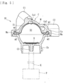
- a blood purification apparatus applied to a first embodiment is a dialysis apparatus for giving dialysis treatment and basically includes, as illustrated in Fig. 1 , a blood circuit including an arterial blood circuit 1 and a venous blood circuit 2, a dialyzer 3 (a blood purifier) provided between the arterial blood circuit 1 and the venous blood circuit 2 and that purifies blood flowing through the blood circuit, a blood pump 4, an air-trap chamber 5 provided to the venous blood circuit 2, a dialysis device 6 that supplies dialysate to the dialyzer 3 and drains waste liquid from the dialyzer 3, a physiological-saline supply line L3 (a substitution-fluid supply line) that allows physiological saline as a substitution fluid to be supplied to the blood circuit, and a storage unit 7 that stores the physiological saline as the substitution fluid.
- a blood circuit including an arterial blood circuit 1 and a venous blood circuit 2, a dialyzer 3 (a blood purifier) provided between the arterial blood circuit 1 and the venous blood circuit 2 and that
- the arterial blood circuit 1 is provided with an arterial puncture needle a connectable to a distal end thereof through a connector, and the blood pump 4, which is of a peristaltic type, at a halfway position thereof.
- the venous blood circuit 2 is provided with a venous puncture needle b connectable to a distal end thereof through a connector, and the air-trap chamber 5 at a halfway position thereof.
- the air-trap chamber 5 is capable of trapping bubbles in the liquid and is provided with a filtering net (not illustrated), thereby being capable of trapping, for example, thrombi and the like at the time of blood return.
- a side on which the puncture needle for blood removal (blood collection) is provided is referred to as the "arterial” side
- a side on which the puncture needle for blood return is provided is referred to as the "venous” side.
- the "arterial” side and the “venous” side are not defined in accordance with which of the artery and the vein is to be the object of puncture.
- the blood pump 4 which is a peristaltic pump provided to the arterial blood circuit 1, is capable of undergoing normal rotation and reverse rotation and causing the liquid in the blood circuit to flow in the direction of rotation thereof.
- the arterial blood circuit 1 includes a squeezable tube that is softer and has a larger diameter than other flexible tubes forming the arterial blood circuit 1.
- the blood pump 4 includes rollers for squeezing the squeezable tube in the direction of liquid delivery. When the blood pump 4 is activated, the rollers rotate and thus squeeze the squeezable tube (a portion of the blood circuit), whereby the liquid in the tube can be made to flow in the direction of rotation (the direction in which the rollers rotate).
- the blood pump 4 When the blood pump 4 is activated to undergo normal rotation (leftward rotation in the drawing) while a patient is punctured with the arterial puncture needle a and the venous puncture needle b, the patient's blood flows through the arterial blood circuit 1 and reaches the dialyzer 3, where the blood is purified. Then, the blood flows through the venous blood circuit 2 while undergoing bubble removal in the air-trap chamber 5 and returns into the patient's body. That is, the patient's blood is purified with the dialyzer 3 while being caused to extracorporeally circulate through the blood circuit from the distal end of the arterial blood circuit 1 to the distal end of the venous blood circuit 2.
- the blood pump 4 When the blood pump 4 is activated to undergo reverse rotation (rightward rotation in the drawing), the blood in the blood circuit (a portion of the arterial blood circuit 1 that is between the distal end and a position where the blood pump 4 is provided) can be returned to the patient.
- the dialyzer 3 has, in a housing thereof, a blood introduction port 3a, a blood delivery port 3b, a dialysate introduction port 3c, and a dialysate delivery port 3d.
- the blood introduction port 3a is connected to the arterial blood circuit 1.
- the blood delivery port 3b is connected to the venous blood circuit 2.
- the dialysate introduction port 3c and the dialysate delivery port 3d are connected to a dialysate introduction line L1 and a dialysate drain line L2, respectively, extending from the dialysis device 6.
- the dialyzer 3 houses a plurality of hollow fibers. Spaces inside the respective hollow fibers form flow routes for blood, and spaces between the inner surface of the housing and the outer surfaces of the hollow fibers form flow routes for dialysate.
- the hollow fibers each have a number of microscopic holes (pores) extending therethrough from the outer surface to the inner surface, thereby forming a hollow fiber membrane. Impurities and the like contained in the blood are allowed to permeate through the hollow fiber membranes into the dialysate.
- the dialysis device 6 includes a liquid delivery unit such as a duplex pump provided over the dialysate introduction line L1 and the dialysate drain line L2.
- a bypass line that bypasses the liquid delivery unit is provided with an ultrafiltration pump for removing water from the patient's blood flowing in the dialyzer 3.
- One end of the dialysate introduction line L1 is connected to the dialyzer 3 (the dialysate introduction port 3c), and the other end is connected to a dialysate supply device (not illustrated) that prepares a dialysate at a predetermined concentration.
- One end of the dialysate drain line L2 is connected to the dialyzer 3 (the dialysate delivery port 3d), and the other end is connected to a drainage unit, not illustrated.
- the dialysate supplied from the dialysate supply device flows through the dialysate introduction line L1 into the dialyzer 3, and further flows through the dialysate drain line L2 into the drainage unit.
- the air-trap chamber 5 is provided with an overflow line extending from the top thereof.
- the overflow line is provided with a clamp unit, such as an electromagnetic valve, at a halfway position thereof.
- the clamp unit such as an electromagnetic valve is opened, the liquid (a priming solution or the like) flowing in the blood circuit can be made to overflow through the overflow line.
- the physiological-saline supply line L3 (the substitution-fluid supply line) is connected at one end thereof to the arterial blood circuit 1 between the position where the blood pump 4 is provided and the distal end of the arterial blood circuit 1 through a T-shaped pipe or the like.
- the physiological-saline supply line L3 forms a flow route (such as a flexible tube or the like) through which the physiological saline (the substitution fluid) to substitute for the blood in the blood circuit is allowed to be supplied to the arterial blood circuit 1.
- the physiological-saline supply line L3 is provided at the other end thereof with the storage unit 7 (a so-called "saline bag"), in which a predetermined amount of physiological saline is stored.
- the physiological-saline supply line L3 is further provided at a halfway position thereof with an air-trap chamber 8.
- the physiological-saline supply line L3 is further provided with a clamp unit 9 (such as an electromagnetic valve or the like).
- the clamp unit 9 is capable of opening and closing the physiological-saline supply line L3, thereby closing and opening the flow route.
- the state of the physiological-saline supply line L3 is arbitrarily switchable by opening or closing the clamp unit 9, between a closed state where the flow route is closed and an open state where the physiological saline (substitution fluid) is allowed to flow.
- the clamp unit 9 may be replaced with a general-purpose device such as a pair of forceps with which the flow route of the physiological-saline supply line L3 can be manually closed and opened.
- the blood circuit applied to the present embodiment is provided with a pressure detector 10.
- the pressure detector 10 is connected to the venous blood circuit 2 at a position between the dialyzer 3 and the air-trap chamber 5 and is capable of detecting the pressure of the blood flowing in the venous blood circuit 2 (the blood circuit). Specifically, as illustrated in Figs.
- the pressure detector 10 includes a case C connectable to the flow route for liquid (in the present embodiment, the venous blood circuit 2 (the blood circuit)), and a membrane member M attached inside the case C and with which a liquid-phase portion S1 to be supplied with the liquid in the flow route (in the present embodiment, the blood in the venous blood circuit 2 (the blood circuit)) and a gas-phase portion S2 to be supplied with air are separated from each other, the membrane member M being displaceable in accordance with the pressure of the liquid (blood) supplied to the liquid-phase portion S1.
- the pressure detector 10 is capable of detecting the pressure of the liquid in the flow route (the venous blood circuit 2) by detecting the pressure in the gas-phase portion S2 with a pressure detection sensor P.
- the case C is a hollow molded component obtained by molding a predetermined resin material or the like.
- the case C is a combination of a liquid-phase-portion case Ca defining the liquid-phase portion S1 and a gas-phase-portion case Cb defining the gas-phase portion S2.
- the liquid-phase-portion case Ca has an inlet port C1 and an outlet port C2 integrally molded therewith.
- the inlet port C1 and the outlet port C2 are each connectable to the flow route for liquid and allow the flow route to communicate with the liquid-phase portion S1.
- the gas-phase-portion case Cb has a connection port C3 integrally molded therewith.
- connection port C3 is connectable to one end of a pipe K, to be described below, and allows the one end to communicate with the gas-phase portion S2.
- the functions of the inlet port C1 and the outlet port C2 of introducing and discharging the liquid may be switched therebetween (that is, the liquid may be discharged from the inlet port C1 while being introduced into the outlet port C2).
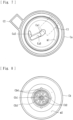
- the liquid-phase-portion case Ca has an annular holding surface m1 (see Fig. 7 ) at the periphery thereof.
- the gas-phase-portion case Cb has an annular holding surface m2 (see Figs. 8 and 9 ) at the periphery thereof.
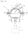
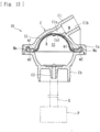
- the membrane member M serves as a diaphragm attached inside the case C and is made of a flexible material that is displaceable or deformable in conformity with pressure change occurring in the liquid-phase portion S1 or the gas-phase portion S2. Specifically, if the pressure of the liquid (the hydraulic pressure) in the liquid-phase portion S1 is low, as illustrated in Fig. 4 , the membrane member M is displaced toward the side of the liquid-phase portion S1, whereby the capacity of the gas-phase portion S2 is increased. If the pressure of the liquid (the hydraulic pressure) in the liquid-phase portion S1 is high, as illustrated in Fig. 6 , the membrane member M is displaced toward the side of the gas-phase portion S2, whereby the capacity of the gas-phase portion S2 is reduced.
- the gas-phase-portion case Cb has an opening Cb1 (see Fig. 8 ) substantially at the center of the bottom thereof.
- the opening Cb1 provided in the inner surface (the bottom) of the gas-phase-portion case Cb allows the flow route in the connection port C3 and the gas-phase portion S2 to communicate with each other. Accordingly, air (gas) is allowed to be introduced into or discharged from the gas-phase portion S2 in accordance with the displacement of the membrane member M.
- the pipe K is connected at one end thereof to the connection port C3 and at the other end thereof to the pressure detection sensor P. Therefore, as air (gas) is introduced or discharged through the opening Cb1 with the displacement of the membrane member M, the pressure detection sensor P can detect the pressure in the gas-phase portion S2.
- the connection port C3 is not limited to the one to be connected to the pipe K and may be connected to another element capable of transmitting the pressure in the gas-phase portion S2 to the pressure detection sensor P.
- the gas-phase-portion case Cb has recesses Cb4 surrounding the opening Cb1 provided at the bottom thereof. Furthermore, as illustrated in Figs. 8 to 10 , the gas-phase-portion case Cb is provided with a hydrophobic membrane B (a hydrophobic portion) that covers the recesses Cb4, inclusive of the opening Cb1.
- the hydrophobic membrane B is provided between the gas-phase portion S2 and the pressure detection sensor P and is formed as a membrane that allows gas to pass therethrough but blocks liquid from passing therethrough.
- the periphery of the hydrophobic membrane B is welded (for example, by ultrasonic welding or the like) to a ridge Cb3 provided around the opening Cb1.
- the hydrophobic membrane B includes a first layer B1 formed as a sheet (film) of a resin material of PTFE (polytetrafluoroethylene), and a second layer B2 formed as a nonwoven fabric of PEs (polyester) or the like.
- the first layer B1 and the second layer B2 are stacked in the thicknesswise direction thereof.
- the total thickness of the first layer B1 and the second layer B2 is about 0.1 to 0.5 mm, with the thickness of the first layer B1 (PTFE) being about one tenth of the total thickness.
- the hydrophobic membrane B according to the present embodiment is obtained by pasting a sheet of PTFE, which serves as the first layer B1, on the surface of the second layer B2, which serves as a base.
- a sheet of PTFE which serves as the first layer B1
- another type of hydrophobic membrane M such as the one including a base made of a different material, or the one including no base
- the first layer B1 only needs to have a characteristic of allowing gas to pass therethrough but blocking liquid from passing therethrough and may be made of, for example, an acrylic copolymer, polyethersulfone, or the like.
- the recesses Cb4 are defined by a plurality of ribs Cb2 (contact portions) projecting radially about the opening Cb1, so that the bending of the hydrophobic membrane B toward the opening Cb1 can be limited.
- the hydrophobic membrane B bends toward the opening Cb1 (toward the recesses Cb4), the hydrophobic membrane B comes into contact with the ribs Cb2, thereby being prevented from bending further.
- spaces around the opening Cb1 spaces in the recesses Cb4 can be preserved. Accordingly, the opening Cb1 can be prevented from being closed at the displacement of the membrane member M.
- the inlet port C1 is a portion (a projected portion) connectable to the flow route for liquid (the blood circuit) and includes, as illustrated in Fig. 4 , a flow-route portion C1a through which the liquid (blood) flows into an inlet opening Ca1 (see Fig. 7 ) of the liquid-phase portion S1, and a connecting portion C1b connectable to the flow route (the blood circuit).
- the flow-route portion C1a and the connecting portion C1b are continuous with each other in the axial direction thereof in the projected portion forming the inlet port C1.
- the liquid in the flow route can be made to flow into the flow-route portion C1a and then into the liquid-phase portion S1 through the inlet opening Ca1.
- the inlet port C1 may be shaped as a recess to which the tube forming the flow route is to be connected.
- the outlet port C2 is a portion (a projected portion) connectable to the flow route for liquid (the blood circuit) and includes, as illustrated in the drawing, a flow-route portion C2a through which the liquid (blood) having flowed into the liquid-phase portion S1 is discharged from an outlet opening Ca2 (see Fig. 7 ), and a connecting portion C2b connectable to the flow route (the blood circuit).
- the flow-route portion C2a and the connecting portion C2b are continuous with each other in the axial direction thereof in the projected portion forming the outlet port C2.
- the liquid having flowed into the liquid-phase portion S1 can be made to flow into the flow-route portion C2a and then to be discharged to a flow route (the blood circuit) on the downstream side.
- the outlet port C2 may be shaped as a recess to which the tube forming the flow route is to be connected.
- the hydrophobic portion (hydrophobic membrane B) that allows gas to pass therethrough but blocks liquid from passing therethrough is provided between the gas-phase portion S2 and the pressure detection sensor P (at the position where the opening Cb1 is provided). Therefore, any blood (liquid) leaked from the liquid-phase portion S1 to the gas-phase portion S2 can be prevented from passing through the connection port C3 and the pipe K and reaching the pressure detection sensor P.
- the hydrophobic portion according to the present invention is the hydrophobic membrane B formed as a membrane. Therefore, the hydrophobic portion can be easily attached to a desired position between the gas-phase portion S2 and the pressure detection sensor P and can be easily processed into a desired shape by cutting or the like.
- the gas-phase portion S2 has the opening Cb1 through which gas is allowed to be introduced into or discharged from the gas-phase portion S2 in accordance with the displacement of the membrane member M. Furthermore, the hydrophobic membrane B (the hydrophobic portion) is provided over the opening Cb1. Therefore, if any blood (liquid) leaks from the liquid-phase portion S1, the leaked blood (liquid) can be prevented from passing through the connection port C3 and reaching the outside of the gas-phase portion S2. Furthermore, the recesses Cb4 are provided around the opening Cb1 of the gas-phase portion S2, and the hydrophobic membrane B (the hydrophobic portion) is provided over the recesses Cb4 inclusive of the opening Cb1.
- the area of the hydrophobic membrane B where air (gas) is allowed to pass can be set large. Accordingly, the resistance at the passage of the air through the hydrophobic membrane B is reduced. Thus, the deterioration in the accuracy of pressure detection by the pressure detection sensor P can be suppressed.
- the recesses Cb4 have the ribs Cb2 (the contact portions) integrally formed therewith and being capable of limiting the bending of the hydrophobic membrane B by coming into contact with the hydrophobic membrane B. Therefore, if the membrane member M that is being displaced toward the side of the gas-phase portion S2 presses and bends the hydrophobic membrane B, the bent hydrophobic membrane B can be prevented from closing the opening Cb1. Furthermore, according to the present embodiment, a blood circuit producing the above advantageous effects of the pressure detector 10 can be provided.
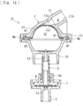
- the hydrophobic membrane B only needs to be provided between the gas-phase portion S2 and the pressure detection sensor P and may be, for example, provided over an outer opening (an opening at the distal end) of the connection port C3 as illustrated in Fig. 12 , or along a side of the membrane member M that faces the gas-phase portion S2 as illustrated in Fig. 13 in such a manner as to displace along with the membrane member M.
- the present invention may be applied to a configuration illustrated in Fig. 14 that includes a connector Ka provided at an end of the pipe K; a connecting portion J provided on the dialysis device 6 and connectable to the connector Ka; and a pipe portion L extending from the connecting portion J to the pressure detection sensor P, in which the hydrophobic membrane B is provided over an opening La of the pipe portion L, the opening La being provided in the connecting portion J.
- the hydrophobic membrane B may be provided at a halfway position of a flow route of the pipe K or the pipe portion L.
- the ribs Cb2 may be omitted or replaced with a contact portion having another shape (such as a ridge or groove having a whirl shape).
- the pressure detector 10 may be connected to the venous blood circuit 2 at a position between the dialyzer 3 and the air-trap chamber 5, the pressure detector 10 may be connected to another position of the blood circuit (for example, a position of the arterial blood circuit 1 between the distal end and the blood pump 4, or a position of the arterial blood circuit 1 between the blood pump 4 and the dialyzer 3).
- the blood circuit to which the present pressure detector 10 is to be connected may be of another type.
- the blood circuit may be provided with not the air-trap chamber 5 but the present pressure detector 10 instead.
- the present invention may be applied to a pressure detector provided to another blood circuit to be used in a treatment of purifying blood of a patient.
- the present invention may be applied to a pressure detector provided to a blood circuit to be used in acetate-free biofiltration (AFBF), continuous slow hemofiltration, hemoadsorption, selective cytapheresis, plasma exchange, double filtration plasmapheresis, plasma adsorption, or the like.
- AFBF acetate-free biofiltration
- the present invention is applicable to any pressure detector of any other type or for any other use, as long as a hydrophobic portion being a hydrophobic membrane formed as a membrane that allows gas to pass therethrough but blocks liquid from passing therethrough is provided between a gas-phase portion and a pressure detection sensor.
Landscapes
- Health & Medical Sciences (AREA)
- Heart & Thoracic Surgery (AREA)
- Vascular Medicine (AREA)
- Life Sciences & Earth Sciences (AREA)
- General Health & Medical Sciences (AREA)
- Anesthesiology (AREA)
- Biomedical Technology (AREA)
- Hematology (AREA)
- Veterinary Medicine (AREA)
- Animal Behavior & Ethology (AREA)
- Engineering & Computer Science (AREA)
- Public Health (AREA)
- Urology & Nephrology (AREA)
- Cardiology (AREA)
- Physics & Mathematics (AREA)
- General Physics & Mathematics (AREA)
- Emergency Medicine (AREA)
- External Artificial Organs (AREA)
- Measuring Fluid Pressure (AREA)
Claims (5)
- Ein Druckdetektor (10), der folgendes beinhaltetein Gehäuse (C), das an einen Strömungsweg für Flüssigkeit anschließbar ist, undein Membranelement (M), das innerhalb des Gehäuses (C) angebracht ist und mit dem ein mit der Flüssigkeit im Strömungsweg zu versorgender Flüssigphasenabschnitt (S1) und ein mit Gas zu versorgender Gasphasenabschnitt (S2) voneinander getrennt sind, wobei das Membranelement (M) als Membran dient und aus einem flexiblen Material besteht, das in Abhängigkeit von einem Druck der dem Flüssigphasenabschnitt (S1) zugeführten Flüssigkeit verlagert oder verformt werden kann,wobei der Druckdetektor (10) den Druck der Flüssigkeit im Strömungsweg erfasst, indem er einen Druck im Gasphasenabschnitt (S2) mit einem Druckerfassungssensor (P) erfasst, wobei der Druckdetektor (10) dadurch gekennzeichnet ist, dass er umfassteinen hydrophoben Abschnitt, der den Durchgang von Gas ermöglicht, aber den Durchgang von Flüssigkeit blockiert, wobei der hydrophobe Abschnitt zwischen dem Gasphasenabschnitt (S2) und dem Druckerfassungssensor (P) vorgesehen ist,wobei der hydrophobe Abschnitt eine hydrophobe Membran (B) ist, die als eine Membran gebildet ist.
- Druckdetektor (10) nach Anspruch 1, wobei der Gasphasenabschnitt (S2) eine Öffnung (Cb1) aufweist, durch die entsprechend der Verlagerung des Membranelements (M) Gas in den Gasphasenabschnitt (S2) eingeleitet oder aus diesem abgeleitet werden kann, und der hydrophobe Abschnitt über der Öffnung (Cb1) vorgesehen ist.
- Druckdetektor (10) nach Anspruch 2, wobei eine Aussparung (Cb4) um die Öffnung (Cb1) des Gasphasenabschnitts (S2) herum vorgesehen ist, und der hydrophobe Abschnitt über der Aussparung (Cb4) einschließlich der Öffnung (Cb1) vorgesehen ist.
- Druckdetektor (10) nach Anspruch 3, wobei die Aussparung (Cb4) einen Kontaktabschnitt aufweist, der in der Lage ist, die Biegung des hydrophoben Abschnitts zu begrenzen, indem er in Kontakt mit dem hydrophoben Abschnitt kommt.
- Blutkreislauf, an den der Druckdetektor (10) nach einem der Ansprüche 1 bis 4 angeschlossen ist.
Applications Claiming Priority (2)
| Application Number | Priority Date | Filing Date | Title |
|---|---|---|---|
| JP2018094464A JP6637108B2 (ja) | 2018-05-16 | 2018-05-16 | 圧力検出器 |
| PCT/JP2019/019395 WO2019221204A1 (ja) | 2018-05-16 | 2019-05-15 | 圧力検出器 |
Publications (3)
| Publication Number | Publication Date |
|---|---|
| EP3777918A1 EP3777918A1 (de) | 2021-02-17 |
| EP3777918A4 EP3777918A4 (de) | 2021-06-02 |
| EP3777918B1 true EP3777918B1 (de) | 2024-11-13 |
Family
ID=68539888
Family Applications (1)
| Application Number | Title | Priority Date | Filing Date |
|---|---|---|---|
| EP19803634.5A Active EP3777918B1 (de) | 2018-05-16 | 2019-05-15 | Druckdetektor |
Country Status (5)
| Country | Link |
|---|---|
| US (1) | US11872334B2 (de) |
| EP (1) | EP3777918B1 (de) |
| JP (1) | JP6637108B2 (de) |
| CN (1) | CN112118878A (de) |
| WO (1) | WO2019221204A1 (de) |
Families Citing this family (7)
| Publication number | Priority date | Publication date | Assignee | Title |
|---|---|---|---|---|
| JP6637108B2 (ja) | 2018-05-16 | 2020-01-29 | 日機装株式会社 | 圧力検出器 |
| JP6637107B2 (ja) | 2018-05-16 | 2020-01-29 | 日機装株式会社 | 圧力検出器 |
| JP7030610B2 (ja) | 2018-05-16 | 2022-03-07 | 日機装株式会社 | 圧力検出器 |
| JP6639559B2 (ja) | 2018-05-16 | 2020-02-05 | 日機装株式会社 | 圧力検出器 |
| JP6694475B2 (ja) | 2018-06-22 | 2020-05-13 | 日機装株式会社 | 医療器具の製造方法及び製造装置 |
| JP6564914B1 (ja) | 2018-06-22 | 2019-08-21 | 日機装株式会社 | 医療器具及びその製造方法 |
| DE102021102993A1 (de) * | 2021-02-09 | 2022-08-11 | Fresenius Medical Care Deutschland Gmbh | Vorrichtung für eine extrakorporale Blutbehandlung |
Family Cites Families (45)
| Publication number | Priority date | Publication date | Assignee | Title |
|---|---|---|---|---|
| FR2346238A1 (fr) | 1976-04-02 | 1977-10-28 | Rhone Poulenc Ind | Reservoir notamment pour liquide biologique |
| US4427470A (en) | 1981-09-01 | 1984-01-24 | University Of Utah | Vacuum molding technique for manufacturing a ventricular assist device |
| JP2582134B2 (ja) | 1988-03-03 | 1997-02-19 | 株式会社 大協精工 | 医薬品用プラスチック容器の栓体及びその製造方法 |
| SE464913B (sv) | 1988-03-03 | 1991-07-01 | Gambro Ab | Anordning foer tryckoeverfoering |
| US4908493A (en) | 1988-05-31 | 1990-03-13 | Midwest Research Institute | Method and apparatus for optimizing the efficiency and quality of laser material processing |
| US5221271A (en) | 1991-08-15 | 1993-06-22 | Medex, Inc. | Sample site with flow directors |
| US5315877A (en) * | 1993-02-19 | 1994-05-31 | Kavlico Corporation | Low cost versatile pressure transducer |
| JPH0924026A (ja) | 1995-07-10 | 1997-01-28 | Otsuka Pharmaceut Factory Inc | 血液回路の圧力測定装置 |
| US5693887A (en) * | 1995-10-03 | 1997-12-02 | Nt International, Inc. | Pressure sensor module having non-contaminating body and isolation member |
| US6392208B1 (en) | 1999-08-06 | 2002-05-21 | Watlow Polymer Technologies | Electrofusing of thermoplastic heating elements and elements made thereby |
| JP2001124647A (ja) * | 1999-10-28 | 2001-05-11 | Koganei Corp | 圧力検出装置 |
| WO2003034014A2 (en) | 2001-10-16 | 2003-04-24 | Innovent, Llc. | Systems and methods for measuring pressure |
| EP1658869A1 (de) | 2004-11-17 | 2006-05-24 | Fresenius Medical Care Deutschland GmbH | Membraneinheit, Gehäuse einer Druckmesseinheit und Druckmesseinheit |
| EP1728526B1 (de) * | 2005-06-03 | 2012-12-26 | Fresenius Medical Care Deutschland GmbH | System zur Überwachung vom Druck in einer Blutbahn, sowie Vorrichtung zum Benutzen mit diesem System |
| JP4488981B2 (ja) | 2005-08-23 | 2010-06-23 | 日本シャーウッド株式会社 | 取出し具及び医療用縫合具セット |
| EP1952833B1 (de) | 2005-10-03 | 2015-02-25 | JMS Co., Ltd. | Geschlossener blutaufbewahrungstank und diesen verwendendes extrakorporales blutzirkulationssystem |
| US8092414B2 (en) | 2005-11-09 | 2012-01-10 | Nxstage Medical, Inc. | Diaphragm pressure pod for medical fluids |
| EP2586472B1 (de) | 2006-04-14 | 2017-08-16 | DEKA Products Limited Partnership | Systeme zum Pumpen von Flüssigkeit |
| CN101421602B (zh) | 2006-04-19 | 2011-02-09 | 旭化成可乐丽医疗株式会社 | 体外循环回路的压力传感器 |
| JP2008051663A (ja) * | 2006-08-24 | 2008-03-06 | Asahi Kasei Kuraray Medical Co Ltd | 圧力センサ |
| JP5141004B2 (ja) | 2006-12-01 | 2013-02-13 | 株式会社ジェイ・エム・エス | 状態検知装置 |
| AU2008219647B2 (en) | 2007-02-27 | 2014-07-10 | Deka Products Limited Partnership | Hemodialysis systems and methods |
| AU2008251056B2 (en) * | 2007-05-15 | 2013-01-10 | Gambro Lundia Ab | Pressure sensing device and use of the same in a connecting structure |
| ITMO20080083A1 (it) * | 2008-03-21 | 2009-09-22 | Lucomed Spa | Dispositivo di raccordo trasduttore-protettore, particolarmente per linee biomedicali di emodialisi |
| EP2229966A1 (de) * | 2009-03-18 | 2010-09-22 | Fresenius Medical Care Deutschland GmbH | Sicherheitseinsatz für extrakorporale Kreisläufe |
| JP5469515B2 (ja) | 2010-04-09 | 2014-04-16 | 内外化成株式会社 | 医療用キャップ |
| JP6116662B2 (ja) * | 2012-03-12 | 2017-04-19 | フレゼニウス メディカル ケア ホールディングス インコーポレイテッド | 液体から気体を排出するための装置および方法 |
| US20140052009A1 (en) | 2012-08-15 | 2014-02-20 | Acist Medical Systems, Inc. | Monitoring blood pressure in a medical injection system |
| WO2014093846A1 (en) | 2012-12-14 | 2014-06-19 | Gambro Renal Products, Inc. | Diaphragm repositioning for pressure pod using position sensing |
| WO2014099767A1 (en) * | 2012-12-20 | 2014-06-26 | Gambro Renal Products, Inc. | Target volume based diaphragm repositioning for pressure measurement apparatus |
| JP2014204779A (ja) * | 2013-04-11 | 2014-10-30 | 日機装株式会社 | トランスデューサ保護フィルタ |
| JP5826815B2 (ja) | 2013-12-11 | 2015-12-02 | 日機装株式会社 | 混注部材 |
| US8960010B1 (en) * | 2013-12-23 | 2015-02-24 | Fresenius Medical Care Holdings, Inc. | Automatic detection and adjustment of a pressure pod diaphragm |
| KR102447625B1 (ko) | 2014-09-26 | 2022-09-28 | 프레제니우스 메디칼 케어 홀딩스 인코퍼레이티드 | 체외 혈액 투석 기계용 압력 출력 디바이스 |
| JP6517023B2 (ja) | 2015-01-23 | 2019-05-22 | 日機装株式会社 | 血液浄化装置 |
| JP6685089B2 (ja) | 2015-06-01 | 2020-04-22 | 日機装株式会社 | 医療用液圧検出装置 |
| JP6901464B2 (ja) | 2015-07-20 | 2021-07-14 | ヘモネティクス・コーポレーションHaemonetics Corporation | 流体流れの圧力を測定するためのシステム及び方法 |
| JP6552400B2 (ja) | 2015-12-10 | 2019-07-31 | アズビル株式会社 | 圧力センサチップ |
| DE102017119708A1 (de) | 2017-08-28 | 2019-02-28 | Kautex Textron Gmbh & Co. Kg | Flüssigkeitsbehälter für ein Kraftfahrzeug und Verfahren zum Herstellen eines Flüssigkeitsbehälters |
| JP7119328B2 (ja) | 2017-10-05 | 2022-08-17 | ニプロ株式会社 | 圧力測定用チャンバ |
| JP6639559B2 (ja) | 2018-05-16 | 2020-02-05 | 日機装株式会社 | 圧力検出器 |
| JP7030610B2 (ja) | 2018-05-16 | 2022-03-07 | 日機装株式会社 | 圧力検出器 |
| JP6637107B2 (ja) | 2018-05-16 | 2020-01-29 | 日機装株式会社 | 圧力検出器 |
| JP6637108B2 (ja) | 2018-05-16 | 2020-01-29 | 日機装株式会社 | 圧力検出器 |
| JP6564914B1 (ja) | 2018-06-22 | 2019-08-21 | 日機装株式会社 | 医療器具及びその製造方法 |
-
2018
- 2018-05-16 JP JP2018094464A patent/JP6637108B2/ja active Active
-
2019
- 2019-05-15 EP EP19803634.5A patent/EP3777918B1/de active Active
- 2019-05-15 CN CN201980031936.1A patent/CN112118878A/zh active Pending
- 2019-05-15 WO PCT/JP2019/019395 patent/WO2019221204A1/ja not_active Ceased
-
2020
- 2020-11-10 US US17/093,823 patent/US11872334B2/en active Active
Also Published As
| Publication number | Publication date |
|---|---|
| JP6637108B2 (ja) | 2020-01-29 |
| US20210052796A1 (en) | 2021-02-25 |
| US11872334B2 (en) | 2024-01-16 |
| EP3777918A1 (de) | 2021-02-17 |
| JP2019198455A (ja) | 2019-11-21 |
| CN112118878A (zh) | 2020-12-22 |
| EP3777918A4 (de) | 2021-06-02 |
| WO2019221204A1 (ja) | 2019-11-21 |
Similar Documents
| Publication | Publication Date | Title |
|---|---|---|
| EP3777918B1 (de) | Druckdetektor | |
| EP3744364B1 (de) | Druckdetektor | |
| US20250213766A1 (en) | Pressure Detector | |
| EP3782672B1 (de) | Druckdetektor | |
| US12324878B2 (en) | Medical device and method of manufacturing the same | |
| US11896751B2 (en) | Adjusting device for pressure detector | |
| EP1398047B1 (de) | Kappe für einen Dialysator, Dialysator und Verfahren zur Entfernung von Gasblasen | |
| JP7033578B2 (ja) | 圧力検出器 | |
| JPS625172Y2 (de) |
Legal Events
| Date | Code | Title | Description |
|---|---|---|---|
| STAA | Information on the status of an ep patent application or granted ep patent |
Free format text: STATUS: THE INTERNATIONAL PUBLICATION HAS BEEN MADE |
|
| PUAI | Public reference made under article 153(3) epc to a published international application that has entered the european phase |
Free format text: ORIGINAL CODE: 0009012 |
|
| STAA | Information on the status of an ep patent application or granted ep patent |
Free format text: STATUS: REQUEST FOR EXAMINATION WAS MADE |
|
| 17P | Request for examination filed |
Effective date: 20201103 |
|
| AK | Designated contracting states |
Kind code of ref document: A1 Designated state(s): AL AT BE BG CH CY CZ DE DK EE ES FI FR GB GR HR HU IE IS IT LI LT LU LV MC MK MT NL NO PL PT RO RS SE SI SK SM TR |
|
| AX | Request for extension of the european patent |
Extension state: BA ME |
|
| A4 | Supplementary search report drawn up and despatched |
Effective date: 20210430 |
|
| RIC1 | Information provided on ipc code assigned before grant |
Ipc: A61M 1/36 20060101AFI20210423BHEP Ipc: G01L 11/00 20060101ALI20210423BHEP Ipc: G01L 19/00 20060101ALI20210423BHEP Ipc: G01L 19/06 20060101ALI20210423BHEP Ipc: G01L 19/14 20060101ALI20210423BHEP Ipc: G01L 7/08 20060101ALI20210423BHEP |
|
| DAV | Request for validation of the european patent (deleted) | ||
| DAX | Request for extension of the european patent (deleted) | ||
| STAA | Information on the status of an ep patent application or granted ep patent |
Free format text: STATUS: EXAMINATION IS IN PROGRESS |
|
| 17Q | First examination report despatched |
Effective date: 20221222 |
|
| P01 | Opt-out of the competence of the unified patent court (upc) registered |
Effective date: 20230523 |
|
| GRAP | Despatch of communication of intention to grant a patent |
Free format text: ORIGINAL CODE: EPIDOSNIGR1 |
|
| STAA | Information on the status of an ep patent application or granted ep patent |
Free format text: STATUS: GRANT OF PATENT IS INTENDED |
|
| INTG | Intention to grant announced |
Effective date: 20240715 |
|
| GRAS | Grant fee paid |
Free format text: ORIGINAL CODE: EPIDOSNIGR3 |
|
| GRAA | (expected) grant |
Free format text: ORIGINAL CODE: 0009210 |
|
| STAA | Information on the status of an ep patent application or granted ep patent |
Free format text: STATUS: THE PATENT HAS BEEN GRANTED |
|
| AK | Designated contracting states |
Kind code of ref document: B1 Designated state(s): AL AT BE BG CH CY CZ DE DK EE ES FI FR GB GR HR HU IE IS IT LI LT LU LV MC MK MT NL NO PL PT RO RS SE SI SK SM TR |
|
| REG | Reference to a national code |
Ref country code: GB Ref legal event code: FG4D |
|
| REG | Reference to a national code |
Ref country code: CH Ref legal event code: EP |
|
| REG | Reference to a national code |
Ref country code: DE Ref legal event code: R096 Ref document number: 602019061999 Country of ref document: DE |
|
| REG | Reference to a national code |
Ref country code: IE Ref legal event code: FG4D |
|
| REG | Reference to a national code |
Ref country code: SE Ref legal event code: TRGR |
|
| REG | Reference to a national code |
Ref country code: LT Ref legal event code: MG9D |
|
| REG | Reference to a national code |
Ref country code: NL Ref legal event code: MP Effective date: 20241113 |
|
| PGFP | Annual fee paid to national office [announced via postgrant information from national office to epo] |
Ref country code: SE Payment date: 20250311 Year of fee payment: 7 |
|
| PG25 | Lapsed in a contracting state [announced via postgrant information from national office to epo] |
Ref country code: PT Free format text: LAPSE BECAUSE OF FAILURE TO SUBMIT A TRANSLATION OF THE DESCRIPTION OR TO PAY THE FEE WITHIN THE PRESCRIBED TIME-LIMIT Effective date: 20250313 Ref country code: IS Free format text: LAPSE BECAUSE OF FAILURE TO SUBMIT A TRANSLATION OF THE DESCRIPTION OR TO PAY THE FEE WITHIN THE PRESCRIBED TIME-LIMIT Effective date: 20250313 Ref country code: HR Free format text: LAPSE BECAUSE OF FAILURE TO SUBMIT A TRANSLATION OF THE DESCRIPTION OR TO PAY THE FEE WITHIN THE PRESCRIBED TIME-LIMIT Effective date: 20241113 |
|
| PG25 | Lapsed in a contracting state [announced via postgrant information from national office to epo] |
Ref country code: FI Free format text: LAPSE BECAUSE OF FAILURE TO SUBMIT A TRANSLATION OF THE DESCRIPTION OR TO PAY THE FEE WITHIN THE PRESCRIBED TIME-LIMIT Effective date: 20241113 Ref country code: NL Free format text: LAPSE BECAUSE OF FAILURE TO SUBMIT A TRANSLATION OF THE DESCRIPTION OR TO PAY THE FEE WITHIN THE PRESCRIBED TIME-LIMIT Effective date: 20241113 |
|
| REG | Reference to a national code |
Ref country code: AT Ref legal event code: MK05 Ref document number: 1741181 Country of ref document: AT Kind code of ref document: T Effective date: 20241113 |
|
| PG25 | Lapsed in a contracting state [announced via postgrant information from national office to epo] |
Ref country code: BG Free format text: LAPSE BECAUSE OF FAILURE TO SUBMIT A TRANSLATION OF THE DESCRIPTION OR TO PAY THE FEE WITHIN THE PRESCRIBED TIME-LIMIT Effective date: 20241113 |
|
| PG25 | Lapsed in a contracting state [announced via postgrant information from national office to epo] |
Ref country code: ES Free format text: LAPSE BECAUSE OF FAILURE TO SUBMIT A TRANSLATION OF THE DESCRIPTION OR TO PAY THE FEE WITHIN THE PRESCRIBED TIME-LIMIT Effective date: 20241113 |
|
| PG25 | Lapsed in a contracting state [announced via postgrant information from national office to epo] |
Ref country code: NO Free format text: LAPSE BECAUSE OF FAILURE TO SUBMIT A TRANSLATION OF THE DESCRIPTION OR TO PAY THE FEE WITHIN THE PRESCRIBED TIME-LIMIT Effective date: 20250213 |
|
| PG25 | Lapsed in a contracting state [announced via postgrant information from national office to epo] |
Ref country code: AT Free format text: LAPSE BECAUSE OF FAILURE TO SUBMIT A TRANSLATION OF THE DESCRIPTION OR TO PAY THE FEE WITHIN THE PRESCRIBED TIME-LIMIT Effective date: 20241113 Ref country code: LV Free format text: LAPSE BECAUSE OF FAILURE TO SUBMIT A TRANSLATION OF THE DESCRIPTION OR TO PAY THE FEE WITHIN THE PRESCRIBED TIME-LIMIT Effective date: 20241113 Ref country code: GR Free format text: LAPSE BECAUSE OF FAILURE TO SUBMIT A TRANSLATION OF THE DESCRIPTION OR TO PAY THE FEE WITHIN THE PRESCRIBED TIME-LIMIT Effective date: 20250214 |
|
| PG25 | Lapsed in a contracting state [announced via postgrant information from national office to epo] |
Ref country code: PL Free format text: LAPSE BECAUSE OF FAILURE TO SUBMIT A TRANSLATION OF THE DESCRIPTION OR TO PAY THE FEE WITHIN THE PRESCRIBED TIME-LIMIT Effective date: 20241113 |
|
| PG25 | Lapsed in a contracting state [announced via postgrant information from national office to epo] |
Ref country code: RS Free format text: LAPSE BECAUSE OF FAILURE TO SUBMIT A TRANSLATION OF THE DESCRIPTION OR TO PAY THE FEE WITHIN THE PRESCRIBED TIME-LIMIT Effective date: 20250213 |
|
| PG25 | Lapsed in a contracting state [announced via postgrant information from national office to epo] |
Ref country code: SM Free format text: LAPSE BECAUSE OF FAILURE TO SUBMIT A TRANSLATION OF THE DESCRIPTION OR TO PAY THE FEE WITHIN THE PRESCRIBED TIME-LIMIT Effective date: 20241113 |
|
| PGFP | Annual fee paid to national office [announced via postgrant information from national office to epo] |
Ref country code: DE Payment date: 20250521 Year of fee payment: 7 |
|
| PG25 | Lapsed in a contracting state [announced via postgrant information from national office to epo] |
Ref country code: DK Free format text: LAPSE BECAUSE OF FAILURE TO SUBMIT A TRANSLATION OF THE DESCRIPTION OR TO PAY THE FEE WITHIN THE PRESCRIBED TIME-LIMIT Effective date: 20241113 |
|
| PGFP | Annual fee paid to national office [announced via postgrant information from national office to epo] |
Ref country code: GB Payment date: 20250522 Year of fee payment: 7 |
|
| PGFP | Annual fee paid to national office [announced via postgrant information from national office to epo] |
Ref country code: IT Payment date: 20250530 Year of fee payment: 7 |
|
| PG25 | Lapsed in a contracting state [announced via postgrant information from national office to epo] |
Ref country code: EE Free format text: LAPSE BECAUSE OF FAILURE TO SUBMIT A TRANSLATION OF THE DESCRIPTION OR TO PAY THE FEE WITHIN THE PRESCRIBED TIME-LIMIT Effective date: 20241113 |
|
| PGFP | Annual fee paid to national office [announced via postgrant information from national office to epo] |
Ref country code: FR Payment date: 20250521 Year of fee payment: 7 |
|
| PG25 | Lapsed in a contracting state [announced via postgrant information from national office to epo] |
Ref country code: RO Free format text: LAPSE BECAUSE OF FAILURE TO SUBMIT A TRANSLATION OF THE DESCRIPTION OR TO PAY THE FEE WITHIN THE PRESCRIBED TIME-LIMIT Effective date: 20241113 |
|
| PG25 | Lapsed in a contracting state [announced via postgrant information from national office to epo] |
Ref country code: SK Free format text: LAPSE BECAUSE OF FAILURE TO SUBMIT A TRANSLATION OF THE DESCRIPTION OR TO PAY THE FEE WITHIN THE PRESCRIBED TIME-LIMIT Effective date: 20241113 |
|
| PG25 | Lapsed in a contracting state [announced via postgrant information from national office to epo] |
Ref country code: CZ Free format text: LAPSE BECAUSE OF FAILURE TO SUBMIT A TRANSLATION OF THE DESCRIPTION OR TO PAY THE FEE WITHIN THE PRESCRIBED TIME-LIMIT Effective date: 20241113 |
|
| REG | Reference to a national code |
Ref country code: DE Ref legal event code: R097 Ref document number: 602019061999 Country of ref document: DE |
|
| PLBE | No opposition filed within time limit |
Free format text: ORIGINAL CODE: 0009261 |
|
| STAA | Information on the status of an ep patent application or granted ep patent |
Free format text: STATUS: NO OPPOSITION FILED WITHIN TIME LIMIT |
|
| 26N | No opposition filed |
Effective date: 20250814 |