EP3774442B1 - Schwebesitz - Google Patents
Schwebesitz Download PDFInfo
- Publication number
- EP3774442B1 EP3774442B1 EP19716346.2A EP19716346A EP3774442B1 EP 3774442 B1 EP3774442 B1 EP 3774442B1 EP 19716346 A EP19716346 A EP 19716346A EP 3774442 B1 EP3774442 B1 EP 3774442B1
- Authority
- EP
- European Patent Office
- Prior art keywords
- seat
- shell
- locking mechanism
- base element
- seat shell
- Prior art date
- Legal status (The legal status is an assumption and is not a legal conclusion. Google has not performed a legal analysis and makes no representation as to the accuracy of the status listed.)
- Active
Links
- 239000003380 propellant Substances 0.000 claims description 21
- 230000001960 triggered effect Effects 0.000 claims description 8
- 239000000463 material Substances 0.000 description 11
- UQMRAFJOBWOFNS-UHFFFAOYSA-N butyl 2-(2,4-dichlorophenoxy)acetate Chemical compound CCCCOC(=O)COC1=CC=C(Cl)C=C1Cl UQMRAFJOBWOFNS-UHFFFAOYSA-N 0.000 description 8
- 229920002943 EPDM rubber Polymers 0.000 description 3
- 241000309551 Arthraxon hispidus Species 0.000 description 2
- OKTJSMMVPCPJKN-UHFFFAOYSA-N Carbon Chemical compound [C] OKTJSMMVPCPJKN-UHFFFAOYSA-N 0.000 description 2
- 239000006260 foam Substances 0.000 description 2
- 239000007779 soft material Substances 0.000 description 2
- 229920002430 Fibre-reinforced plastic Polymers 0.000 description 1
- 239000004952 Polyamide Substances 0.000 description 1
- 229910052799 carbon Inorganic materials 0.000 description 1
- 239000011248 coating agent Substances 0.000 description 1
- 238000000576 coating method Methods 0.000 description 1
- 239000002131 composite material Substances 0.000 description 1
- 238000006073 displacement reaction Methods 0.000 description 1
- 239000011151 fibre-reinforced plastic Substances 0.000 description 1
- 239000010439 graphite Substances 0.000 description 1
- 229910002804 graphite Inorganic materials 0.000 description 1
- 238000000034 method Methods 0.000 description 1
- 238000000465 moulding Methods 0.000 description 1
- 239000004033 plastic Substances 0.000 description 1
- 229920003023 plastic Polymers 0.000 description 1
- 229920002647 polyamide Polymers 0.000 description 1
- 230000001681 protective effect Effects 0.000 description 1
- 238000007788 roughening Methods 0.000 description 1
Images


Classifications
-
- B—PERFORMING OPERATIONS; TRANSPORTING
- B60—VEHICLES IN GENERAL
- B60N—SEATS SPECIALLY ADAPTED FOR VEHICLES; VEHICLE PASSENGER ACCOMMODATION NOT OTHERWISE PROVIDED FOR
- B60N2/00—Seats specially adapted for vehicles; Arrangement or mounting of seats in vehicles
- B60N2/02—Seats specially adapted for vehicles; Arrangement or mounting of seats in vehicles the seat or part thereof being movable, e.g. adjustable
- B60N2/04—Seats specially adapted for vehicles; Arrangement or mounting of seats in vehicles the seat or part thereof being movable, e.g. adjustable the whole seat being movable
- B60N2/14—Seats specially adapted for vehicles; Arrangement or mounting of seats in vehicles the seat or part thereof being movable, e.g. adjustable the whole seat being movable rotatable, e.g. to permit easy access
- B60N2/146—Seats specially adapted for vehicles; Arrangement or mounting of seats in vehicles the seat or part thereof being movable, e.g. adjustable the whole seat being movable rotatable, e.g. to permit easy access characterised by the locking device
-
- B—PERFORMING OPERATIONS; TRANSPORTING
- B60—VEHICLES IN GENERAL
- B60N—SEATS SPECIALLY ADAPTED FOR VEHICLES; VEHICLE PASSENGER ACCOMMODATION NOT OTHERWISE PROVIDED FOR
- B60N2/00—Seats specially adapted for vehicles; Arrangement or mounting of seats in vehicles
- B60N2/02—Seats specially adapted for vehicles; Arrangement or mounting of seats in vehicles the seat or part thereof being movable, e.g. adjustable
- B60N2/04—Seats specially adapted for vehicles; Arrangement or mounting of seats in vehicles the seat or part thereof being movable, e.g. adjustable the whole seat being movable
- B60N2/10—Seats specially adapted for vehicles; Arrangement or mounting of seats in vehicles the seat or part thereof being movable, e.g. adjustable the whole seat being movable tiltable
-
- B—PERFORMING OPERATIONS; TRANSPORTING
- B60—VEHICLES IN GENERAL
- B60N—SEATS SPECIALLY ADAPTED FOR VEHICLES; VEHICLE PASSENGER ACCOMMODATION NOT OTHERWISE PROVIDED FOR
- B60N2/00—Seats specially adapted for vehicles; Arrangement or mounting of seats in vehicles
- B60N2/02—Seats specially adapted for vehicles; Arrangement or mounting of seats in vehicles the seat or part thereof being movable, e.g. adjustable
- B60N2/04—Seats specially adapted for vehicles; Arrangement or mounting of seats in vehicles the seat or part thereof being movable, e.g. adjustable the whole seat being movable
- B60N2/14—Seats specially adapted for vehicles; Arrangement or mounting of seats in vehicles the seat or part thereof being movable, e.g. adjustable the whole seat being movable rotatable, e.g. to permit easy access
-
- B—PERFORMING OPERATIONS; TRANSPORTING
- B60—VEHICLES IN GENERAL
- B60N—SEATS SPECIALLY ADAPTED FOR VEHICLES; VEHICLE PASSENGER ACCOMMODATION NOT OTHERWISE PROVIDED FOR
- B60N2/00—Seats specially adapted for vehicles; Arrangement or mounting of seats in vehicles
- B60N2/24—Seats specially adapted for vehicles; Arrangement or mounting of seats in vehicles for particular purposes or particular vehicles
- B60N2/42—Seats specially adapted for vehicles; Arrangement or mounting of seats in vehicles for particular purposes or particular vehicles the seat constructed to protect the occupant from the effect of abnormal g-forces, e.g. crash or safety seats
- B60N2/4249—Seats specially adapted for vehicles; Arrangement or mounting of seats in vehicles for particular purposes or particular vehicles the seat constructed to protect the occupant from the effect of abnormal g-forces, e.g. crash or safety seats fixed structures, i.e. where neither the seat nor a part thereof are displaced during a crash
-
- B—PERFORMING OPERATIONS; TRANSPORTING
- B60—VEHICLES IN GENERAL
- B60N—SEATS SPECIALLY ADAPTED FOR VEHICLES; VEHICLE PASSENGER ACCOMMODATION NOT OTHERWISE PROVIDED FOR
- B60N2/00—Seats specially adapted for vehicles; Arrangement or mounting of seats in vehicles
- B60N2/24—Seats specially adapted for vehicles; Arrangement or mounting of seats in vehicles for particular purposes or particular vehicles
- B60N2/42—Seats specially adapted for vehicles; Arrangement or mounting of seats in vehicles for particular purposes or particular vehicles the seat constructed to protect the occupant from the effect of abnormal g-forces, e.g. crash or safety seats
- B60N2/427—Seats or parts thereof displaced during a crash
- B60N2/42772—Seats or parts thereof displaced during a crash characterised by the triggering system
- B60N2/4279—Seats or parts thereof displaced during a crash characterised by the triggering system electric or electronic triggering
-
- B—PERFORMING OPERATIONS; TRANSPORTING
- B60—VEHICLES IN GENERAL
- B60N—SEATS SPECIALLY ADAPTED FOR VEHICLES; VEHICLE PASSENGER ACCOMMODATION NOT OTHERWISE PROVIDED FOR
- B60N2/00—Seats specially adapted for vehicles; Arrangement or mounting of seats in vehicles
- B60N2/24—Seats specially adapted for vehicles; Arrangement or mounting of seats in vehicles for particular purposes or particular vehicles
- B60N2/42—Seats specially adapted for vehicles; Arrangement or mounting of seats in vehicles for particular purposes or particular vehicles the seat constructed to protect the occupant from the effect of abnormal g-forces, e.g. crash or safety seats
- B60N2/43—Safety locks
-
- B—PERFORMING OPERATIONS; TRANSPORTING
- B60—VEHICLES IN GENERAL
- B60N—SEATS SPECIALLY ADAPTED FOR VEHICLES; VEHICLE PASSENGER ACCOMMODATION NOT OTHERWISE PROVIDED FOR
- B60N2/00—Seats specially adapted for vehicles; Arrangement or mounting of seats in vehicles
- B60N2/02—Seats specially adapted for vehicles; Arrangement or mounting of seats in vehicles the seat or part thereof being movable, e.g. adjustable
- B60N2002/0204—Seats specially adapted for vehicles; Arrangement or mounting of seats in vehicles the seat or part thereof being movable, e.g. adjustable characterised by the seat or seat part turning about or moving along a non-standard, particular axis, i.e. an axis different from the axis characterising the conventional movement
- B60N2002/0212—Seats specially adapted for vehicles; Arrangement or mounting of seats in vehicles the seat or part thereof being movable, e.g. adjustable characterised by the seat or seat part turning about or moving along a non-standard, particular axis, i.e. an axis different from the axis characterising the conventional movement the seat or seat part turning about or moving along a longitudinal axis
-
- B—PERFORMING OPERATIONS; TRANSPORTING
- B60—VEHICLES IN GENERAL
- B60N—SEATS SPECIALLY ADAPTED FOR VEHICLES; VEHICLE PASSENGER ACCOMMODATION NOT OTHERWISE PROVIDED FOR
- B60N2/00—Seats specially adapted for vehicles; Arrangement or mounting of seats in vehicles
- B60N2/02—Seats specially adapted for vehicles; Arrangement or mounting of seats in vehicles the seat or part thereof being movable, e.g. adjustable
- B60N2002/0204—Seats specially adapted for vehicles; Arrangement or mounting of seats in vehicles the seat or part thereof being movable, e.g. adjustable characterised by the seat or seat part turning about or moving along a non-standard, particular axis, i.e. an axis different from the axis characterising the conventional movement
- B60N2002/0216—Seats specially adapted for vehicles; Arrangement or mounting of seats in vehicles the seat or part thereof being movable, e.g. adjustable characterised by the seat or seat part turning about or moving along a non-standard, particular axis, i.e. an axis different from the axis characterising the conventional movement the seat or seat part turning about or moving along a transversal axis
-
- B—PERFORMING OPERATIONS; TRANSPORTING
- B60—VEHICLES IN GENERAL
- B60N—SEATS SPECIALLY ADAPTED FOR VEHICLES; VEHICLE PASSENGER ACCOMMODATION NOT OTHERWISE PROVIDED FOR
- B60N2/00—Seats specially adapted for vehicles; Arrangement or mounting of seats in vehicles
- B60N2/02—Seats specially adapted for vehicles; Arrangement or mounting of seats in vehicles the seat or part thereof being movable, e.g. adjustable
- B60N2002/0204—Seats specially adapted for vehicles; Arrangement or mounting of seats in vehicles the seat or part thereof being movable, e.g. adjustable characterised by the seat or seat part turning about or moving along a non-standard, particular axis, i.e. an axis different from the axis characterising the conventional movement
- B60N2002/022—Seats specially adapted for vehicles; Arrangement or mounting of seats in vehicles the seat or part thereof being movable, e.g. adjustable characterised by the seat or seat part turning about or moving along a non-standard, particular axis, i.e. an axis different from the axis characterising the conventional movement the seat or seat part turning about or moving along a vertical axis
Definitions
- the invention relates to a floating seat, in particular a lockable floating seat for a vehicle, in particular a vehicle seat that can be tilted relative to a body floor.
- floating seats are known (see e.g. ES-A-2 184 564 ) to maximize comfort.
- a locking mechanism for locking or unlocking the floating seat takes a few seconds.
- adjustment of the seat while driving is undesirable for safety reasons.
- the object of the present invention is to provide a floating seat with improved comfort and better safety.
- a floating seat comprising a base or carrier element and a seat shell, an adjustment mechanism in the form of a joint or slide bearing, in particular a ball joint or shell slide bearing, being formed between the seat shell and the base element, the seat shell being formed by means of the adjustment mechanism is adjustable in at least two or all three degrees of freedom of rotation relative to the base element.
- a floating seat comprising a base or carrier element, an adapter element and a seat shell, at least between the seat shell and the adapter element and / or between the adapter element and the base element each having an adjustment mechanism in the form of a joint or slide bearing, in particular a ball and socket joint. or shell sliding or multi-sliding surface bearing is, wherein the seat shell is adjustable in at least two or in all three degrees of freedom of rotation relative to the base element by means of the adjustment mechanism.
- the seat shell can be tilted at least about a transverse axis and rotated about a vertical axis relative to the base element by means of the adjustment mechanism.
- the seat shell can be inclined or rolled around a transverse axis in a range between 0 ° and 120 ° in the longitudinal direction relative to the base element and / or inclined or rolled and / or around in the transverse direction around a longitudinal axis in a range between 0 ° and 5 ° a vertical axis of the floating seat can be rotated or swiveled up to a maximum of 20 °.
- the seat shell assumes a position in which the seat shell is oriented forwards in the longitudinal direction and thus in the direction of travel / viewing.
- This position is also referred to as the 0 ° position in relation to the vertical axis (Z-axis) and longitudinal axis (X-axis).
- the seat shell is inclined backwards around the transverse axis (Y-axis), for example 25 °, for improved seating comfort.
- the seat shell can be inclined up to 10 ° forwards and up to 20 ° backwards relative to the design or sitting position, for example about the transverse axis.
- the seat shell can be tilted up to a maximum of 120 ° around the transverse axis.
- the seat shell can in particular be rotated by a maximum of 280 ° around the vertical axis, in particular rotatable by -90 ° up to + 190 ° in relation to the design or sitting position.
- the sliding bearing is designed as a shell sliding bearing or a multiple sliding surface bearing.
- the sliding bearing comprises several separate sliding surfaces which are arranged and / or shaped in such a way that a spherical shell-shaped sliding bearing is formed between the base element and the seat shell.
- the seat shell has a single or a plurality of spherical shell-shaped sliding surfaces corresponding to these partial sliding surfaces.
- the base element and the seat shell can each have a single sliding surface which is designed to correspond to one another, for example in the shape of a spherical shell.
- the seat shell In the unlocked state, the seat shell can thus be moved, in particular pivoted or inclined, in several degrees of freedom, in particular in all degrees of freedom of rotation. In the locked state, the seat shell is blocked.
- a floating seat comprising a base or carrier element, an optional adapter element and a seat shell, with a locking mechanism for locking and / or unlocking an adjustment of the seat shell relative to the base element, the locking mechanism being actuatable by means of a release mechanism is, and wherein the trigger mechanism is set up to manually or electrically actuate the locking mechanism in normal operation for unlocking or locking the adjustment of the seat pan relative to the base element and optionally or additionally to actuate it automatically in the event of a collision in order to automatically adjust the seat pan relative to the base element lock.
- the locking mechanism is designed in particular in normal operation as a continuous or stepless locking or arresting device.
- the locking mechanism can be actuated continuously or steplessly, for example by means of an electric motor, in normal operation by means of the release mechanism, in particular movable between an unlocked position and a locked position or vice versa.
- the locking mechanism has, for example, an electromechanical drive unit which interacts with a brake unit, for example a wedge brake unit.
- the electromechanical drive unit is designed to brake and / or lock or unlock an adjustment of the seat shell relative to the base element in the longitudinal and vertical directions.
- the brake unit in particular a wedge brake unit, is set up to brake and / or stop, in particular to lock or unlock, an adjustment of the seat shell relative to the base element in the transverse and vertical directions.
- the electromechanical drive unit is designed as a motor-gear unit, for example a drive motor in combination with a spindle drive.
- the braking unit comprises, for example, opposing braking, wedge and / or friction surfaces.
- a braking surface has a spherical shape which slides on a braking, sliding or guide surface inclined in opposite directions and thereby brakes.
- the locking mechanism can be actuated automatically and continuously or steplessly by means of the trigger mechanism, for example by means of a pyrotechnic propellant, in particular it can be moved into a locked position.
- the floating seat is designed in such a way that a position of the seat shell relative to the base element in at least two or more degrees of freedom, in particular in at least one or more degrees of translational freedom, such as in the vertical direction or longitudinal direction, and / or in at least one or more degrees of freedom of rotation, for example in the vertical direction of rotation or horizontal direction of rotation by a vertical, Longitudinal and / or transverse axis, is adjustable.
- An adjustment mechanism is provided for this purpose, for example. Setting the position of the seat shell in more than two degrees of freedom, in particular degrees of freedom of rotation, creates the impression of a floating or sliding seat shell that follows a movement of a user on the seat.
- the adjustment mechanism is designed, for example, in the form of a joint or sliding bearing, in particular a ball joint or ball bearing.
- the joint or sliding bearing has a spherical sliding surface in which a spherical running surface slides.
- the spherical sliding surface on the base element is formed in the direction of the seat shell, the seat shell itself and / or the adapter element having a running surface that corresponds to the spherical sliding surface on the base element, or vice versa.
- the spherical sliding surface has a concave shape and the spherical running surface has a corresponding convex shape.
- the joint or sliding bearing can also be designed as a self-aligning or shell sliding bearing.
- the pendulum bearing has, for example, a pendulum or oscillating or sliding shell or joint socket in which a joint head or a spherical shell slides.
- the seat shell In the unlocked state, the seat shell can therefore be moved, in particular pivoted or inclined, in several degrees of freedom. In the locked state, the seat shell is blocked.
- the locking mechanism is designed, in particular, as a mechanical connection, for example a latching connection, a plug connection or another suitable form-fit or force-fit connection, in particular a friction connection.
- the locking and / or braking mechanism is designed as a plug-in and / or latching connection.
- the locking and / or braking mechanism can alternatively or additionally be designed as a force, in particular frictional connection.
- the release mechanism comprises an electric motor or servomotor for electrically actuating the locking mechanism of the seat.
- the electric motor drives a locking element directly or indirectly via a threaded rod to the locking element, which is designed, for example, as a slide, in particular a wedge or latching plate, so that this locking element can be moved in or out depending on the direction of movement reaches a locking engagement.
- the triggering mechanism comprises a pyrotechnic propellant charge in order to automatically trigger the locking mechanism and to place it in a locking position.
- the pyrotechnic propellant charge is designed as a pyrotechnic actuator which drives a piston which moves a locking element, in particular a wedge or latching plate, so that this locking element is placed in a locking position.
- the advantages achieved with the invention are, in particular, that in normal operation the seat shell can be pivoted, in particular moved, by means of only one operation, and in the event of a collision the seat shell can be locked against movement in the millisecond range.
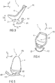
- Figures 1A and 1B show schematically in two perspective representations, one from the front and one from the rear, a swivel or floating seat 1, in particular a vehicle seat that can be moved, in particular swiveled, rotated and / or inclined in several degrees of freedom F1 to F3.
- the floating seat 1 is in particular provided in a vehicle and attached there to a vehicle floor in a manner not shown.
- the floating seat 1 comprises at least one carrier or base element 2, an optional adapter element 3 and a seat shell 4 ( Figure 1B ).
- the seat shell 4 can be shaped and designed accordingly and arranged and supported directly on the base element 2 ( Figure 1A ).
- the adapter element 3 can be part of the bottom of the seat shell 4.
- the seat shell 4 can also be formed in one piece from a seat part 4.1 and a seat back 4.2. Alternatively, the seat shell 4 can be formed from a separate seat part 4.1 and a seat back 4.2 arranged inclinable on this (not shown in more detail).
- the seat shell 4 can furthermore be formed from a carrier 4.3, in particular a rigid foam shell or composite shell, in particular made of a fiber-reinforced plastic, and a cushion element 4.4 arranged on this, in particular a foam cushion with or without a cover.
- an adjusting mechanism 6 in the form of a joint or sliding bearing G is formed in each case.
- the seat shell 4 is thus mounted on the base element 2 in a sliding, in particular tilting, rotating and / or pivoting manner, directly or indirectly via the adapter element 3.
- the adjustment mechanism 6 the seat shell 4 is slidably mounted relative to the base element 2 for adjustment V in at least two or all three degrees of freedom of rotation R1, R2 and / or R3.
- the seat shell 4 assumes a position in which the seat shell 4 is forward in the longitudinal direction X. and is thus aligned in the direction of travel / sight.
- This seat position P1 is also referred to as the 0 ° position in relation to the vertical axis Z0 and longitudinal axis X0.
- the seat shell 4 is inclined to the rear about the transverse axis Y0, for example by 25 °, for improved seating comfort.
- the sliding bearing G is set up in such a way that the seat shell 4 can be inclined up to 10 ° forwards and up to 20 ° backwards with respect to the design or seat position P1, for example about the transverse axis Y0 and can be inclined backwards up to a maximum of 120 ° and / or rotatable about the vertical axis Z0 in particular up to a maximum of 280 °, in particular rotatable by -90 ° up to + 190 °.
- the adjustment mechanism 6 is designed, for example, in the manner of a shell sliding bearing 6.1.
- the adjusting mechanism 6 can also be designed in the manner of a ball joint.
- the floating seat 1 comprises a carrier or base element 2, an adapter element 3 and a seat shell 4, at least between seat shell 4 and adapter element 3 and between adapter element 3 and base element 2 each an adjustment mechanism 6 in the manner of a slide bearing G, in particular a ball joint or shell sliding bearing, and the seat shell 4 is adjustable by means of such a multiple adjustment mechanism 6 in at least two or all three degrees of freedom of rotation R1, R2 and / or R3 relative to the base element 2 (not shown in detail).
- the seat shell 4 can be inclined relative to the base element 2 about a transverse axis Y0 from a normal position to a comfort position in a range between 0 ° and 120 ° and / or inclined and / or around a longitudinal axis X0 in a range between 0 ° and 5 ° a vertical axis Z0 can be rotated up to a maximum of 20 °.
- the floating seat 1 is designed such that a position of the seat shell 4 relative to the base element 2 in at least two or more degrees of freedom F1 to F3, in particular in at least one or more translational degrees of freedom T1, T2, such as in the vertical direction Z and / or Longitudinal direction X, and / or can be set in at least one or more of the rotational degrees of freedom R1, R2, R3.
- the adjustment mechanism 6 is provided for this purpose.
- a locking mechanism 5 which fixes the seat shell 4 in the set position relative to the base element 2.
- the locking mechanism 5 is described in more detail below with the aid of examples.
- the locking mechanism 5 can be arranged in the adapter element 3.
- the locking mechanism 5 comprises an electromechanical drive unit 12 which interacts with a brake unit 14 which engages between the seat shell 4 and the base element 2.
- FIGS 1C to 1E show schematically in a perspective illustration a further exemplary embodiment for a floating seat 100, an upholstery with a seat shell 40 and an adapter element 30 between which a multi-sliding surface bearing 61 as an adjusting mechanism 60 (shown in FIG Figure 1C ) is trained.
- the adapter element 30 is fastened to the base element 20, in particular to a lateral seat frame 37, by means of fastening bolts 35 and / or fastening flanges 36.
- Figures 1C and 1D show the seat shell 40 with a seat part 41 which has a spherical shell-shaped sliding surface 41.1 in the direction of the adapter element 30.
- the sliding surface 41.1 is designed in the shape of a spherical shell.
- the sliding surface 41.1 can be divided into several partial sliding surfaces. Alternatively, this can be designed as a single concave-shaped surface or a concave-shaped surface with a plurality of partial sliding surfaces.
- the seat shell 40 is designed as a one-piece frame shell 42, in particular an injection-molded frame shell or a shell produced in another suitable molding process.
- connection points 43 for a seat belt 44 are provided on the frame shell 42 itself.
- connection points 43 for a three-point belt are provided on the frame shell 42 itself.
- FIG 1E shows an exemplary embodiment for the adapter element 30.
- the adapter element 30 has a concave surface shape 32, which in FIG Direction of the seat shell 40, in particular of the seat part 41.
- the concave surface shape 32 has several partial sliding surfaces 33.
- the partial sliding surfaces 33 are shaped like a spherical shell or concave.
- the partial sliding surfaces 33 form point bearings for the corresponding sliding surface 41.1 of the seat part 41 or their partial sliding surfaces, not shown.
- the partial sliding surfaces 33 are made of a different material, in particular a suitable sliding material, such as a plastic, graphite, carbon, EPDM, than the material of the adapter element 30.
- the sliding material has, in particular, a low coefficient of sliding friction, high wear resistance and high mechanical strength, as well as dimensional stability and temperature resistance.
- the opposing surfaces forming the sliding bearing G - partial sliding surfaces 33 of the adapter element 30 and sliding surface 41.1 of the seat shell 40 - can also be formed from different materials.
- one of the surfaces is made of a particularly hard material with a high modulus of elasticity and the other is made of a soft material with a low modulus of elasticity.
- the partial sliding surfaces 33 are attached to the adapter element 30 at a distance from one another and pointing in the direction of the seat shell 40.
- the adapter element 30 has a recess 34 through which the brake unit 14 and the locking mechanism 5 for braking the movement of the seat shell 40 relative to the adapter element 30 up to locking the seat shell 40 and adapter element 30 and thus the movement or positioning of the floating seat 100 engages relative to the base element 20 in a set position.
- the brake unit 14 and the locking mechanism 5 are described in more detail below.
- Figure 2 shows a schematic sectional illustration of an exemplary embodiment for an adjusting mechanism 6 in the manner of a slide bearing G with a shell slide bearing 6.1 for the swivel or floating seat 1.
- the floating seat 1 comprises the base element 2 for attachment to a body in a vehicle.
- the base element 2 is designed in such a way that it accommodates further conventional functional elements, such as a longitudinal adjustment unit 10 and / or a height adjustment unit 11 with an associated drive unit 12, for adjusting the floating seat 1 in one or more degrees of translational freedom T1 and T2 in the longitudinal direction X or vertical direction Z. can.
- the sliding or joint bearing G has a spherical sliding surface 2.1 in which a spherical running surface 3.1 slides.
- the spherical sliding surface 2.1 is formed on the base element 2 in the direction of the seat shell 4.
- the spherical counter or running surface 3.1 is formed on the adapter element 3.
- the seat shell 4 itself can have a running surface corresponding to the spherical sliding surface 2.1 of the base element 2.
- the spherical sliding surface 2.1 has a concave shape and the spherical running surface 3.1 has a corresponding convex shape.
- the shell sliding bearing 6.1 can also be designed as a spherical plain bearing G, a ball joint or a self-aligning bearing.
- the self-aligning bearing has, for example, a pendulum or oscillating shell or joint socket in which a joint head or a spherical shell rolls.
- the seat shell 4 In the unlocked state of the locking mechanism 5, the seat shell 4 can be moved, in particular pivoted or inclined, in several degrees of freedom F1 to F3, in particular in all degrees of freedom of rotation R1 to R3, relative to the base element 2. In the locked state, the seat shell 4 is blocked with respect to the base element 2 and cannot be adjusted.
- Figures 3 to 5 show schematically in a perspective representation the floating seat 1 in different positions P1 to P3 and with different adjustable degrees of freedom F1 to F3, in particular the degrees of freedom of rotation R1 to R3.
- the floating seat 1 can, for example, in at least one or more degrees of translational freedom T1, T2, such as in the vertical direction Z, in the longitudinal direction X or in the transverse direction Y, and / or in at least one or more rotational degrees of freedom R1 to R3, for example in the vertical direction of rotation or the horizontal direction of rotation a vertical, longitudinal and / or transverse axis, be adjustable.
- the adjusting mechanism 6 is provided for this purpose, for example.
- Figure 3 shows the floating seat 1 in a slightly inclined or pivoted position P1 in the longitudinal direction X to the rear, in which the seat shell 4 about the transverse axis Y0 between a normal position and a Comfort position, in particular a sitting or lying comfort position, can be inclined in a range from 0 ° to a maximum of 180 ° with respect to the normal position, in particular a largely vertical position of the seat back 4.2.
- Figure 4 shows the floating seat 1 in a position P2 rotated about a vertical axis Z0 compared to a normal position in which the floating seat 1 is oriented in the direction of travel, for example in a vehicle.
- the adjustment mechanism 6 is set up to rotate or pivot the floating seat 1 between the normal position and a rotated position in a range of up to a maximum of 20 °.
- Figure 5 shows the floating seat 1 in a slightly inclined or pivoted position P3 to the side about the longitudinal axis X0, in which the seat shell 4 about the longitudinal axis X0 between a normal position and a position inclined to the side in a range of up to a maximum of 5 ° relative to the normal position, in particular a largely horizontal position of the seat part 4.1, inclined or rolled.
- Figure 6 shows a schematic exploded view of the swivel or floating seat 1, comprising at least the base element 2, the adapter element 3 and the seat shell 4.
- the locking mechanism 5 with an integrated brake unit 14 is arranged between the base element 2 and the adapter element 3.
- the brake unit 14 is designed, for example, as a wedge brake unit 13, which can include a brake element 9, in particular a brake shell or plate.
- the locking mechanism 5 is activated by means of a release mechanism 7 (shown in FIG Figures 7A through 10 ) can be actuated, in particular locked or unlocked.
- the trigger mechanism 7 can be used, for example, for normal adjustment of the seat shell 4 by a user and thus be designed electrically in normal operation and include a servomotor 7.1 (shown in Figures 7A to 7C ).
- the trigger mechanism 7 additionally includes a pyrotechnic propellant 7.4, by means of which the seat shell 4 is automatically locked against movement within a few milliseconds, in particular less than 10 ms (shown in FIGS Figures 8A through 10 ).
- the trigger mechanism 7 is set up in operative connection with the locking mechanism 5 to electrically lock or unlock an adjustment of the seat shell 4 during normal operation (shown by way of example in FIG Figures 7A to 7C ) and optionally to lock the adjustment of the seat shell 4 reversibly in the event of a collision (shown as an example in Figures 8A through 10 ).
- the seat shell 4 in particular its adjustment mechanism 6, can be decoupled from the base element 2 and blocked or fixed against displacement relative to the base element 2.
- a fastening element 8 for example a fastening plate or foot, is provided for fastening the adjustment mechanism 6.
- the fastening element 8 can be fastened in or on the base element 2.
- the floating seat 1 is designed, for example, in such a way that a position of the seat shell 4 can be adjusted in at least two or more degrees of freedom F1 to F3.
- the floating seat 1 can optionally be provided with a rail system for a longitudinal adjustment unit 10 in order to be able to be adjusted, for example, in the longitudinal direction X and thus in the translational direction.
- the adjustment mechanism 6 is designed to adjust the seat shell 4 in the degrees of freedom of rotation R1 to R3, for example in the manner of a shell sliding bearing 6.1 or sliding or joint bearing G.
- the shell sliding bearing 6.1 has a spherical sliding surface 6.2 in which a running surface 6.3 slides.
- the spherical sliding surface 6.2 can be formed on the base element 2 in the direction of the seat shell 4, the seat shell 4 itself (not shown) or the adapter element 3 having a running surface 6.3 corresponding to the spherical sliding surface 6.2 of the base element 2.
- a separate brake element 9 in particular a friction / brake plate or friction / brake shell or skate plate, can be provided between adapter element 3 and base element 2.
- the braking element 9 can have a braking surface in the direction of the adapter element 3, which corresponds to the running surface 3.1 of the adapter element 3, and a running surface 6.3 in the direction of the base element 2, which corresponds to the sliding surface 2.1 of the base element 2.
- the sliding bearing G and in particular the respective shell sliding bearing 6.1 between base element 2 and braking element 9 as well as between braking element 9 and adapter element 3 and between adapter element 3 and seat shell 4 can be designed as a self-aligning bearing.
- the pendulum bearing has, for example, a pendulum or oscillating shell with a corresponding sliding surface 6.2.
- the seat shell In the unlocked state, the seat shell can thus be moved, in particular pivoted or inclined, in several degrees of freedom F1 to F3. In the locked state, the seat shell 4 and thus the floating seat 1 are blocked.
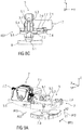
- Figure 7A shows schematically in a perspective illustration an embodiment of a locking mechanism 5 for a floating seat 1 in normal operation in the unlocked position E1 with a electrical release mechanism 7 for actuating the locking mechanism 5 in normal operation, in particular when a user wishes to adjust the floating seat 1.
- the locking mechanism 5 is designed, in particular, as a mechanical connection, for example a latching connection, a plug connection or another suitable form-fit or force-fit connection.
- the locking mechanism 5 comprises a locking element, for example a locking bolt 5.1, which can be or is set into a locked position E2 by means of an adjusting element 5.2.
- the locking bolt 5.1 is arranged and supported on the adjusting element 5.2, for example by means of a slide 5.3.
- the locking bolt 5.1 is attached to the slide 5.3 by means of a pin, for example.
- the slide 5.3 is movably arranged on a guide surface 5.4 of the adjusting element 5.2, in particular a wedge element or a wedge plate.
- the adjustment element 5.2 is movably arranged on a, in particular inclined or wedge-shaped guide surface 5.7 of a carrier or base element 5.5, in particular guided, for example arranged so that it can be pulled (in normal operation) or pushed (in the event of a collision).
- Figure 7B shows the unlocked position E1 of the floating seat 1, in which the adjusting element 5.2 and thus the locking bolt 5.1 are placed in a lower unlocked position E1, in which the seat shell 4 can be moved freely.
- the adjusting element 5.2 and thus the locking bolt 5.1 are placed in a lower unlocked position E1 with respect to the base element 2, in which the braking element 9 and the seat shell 4 are released, for example decoupled from one another and have no contact, and are not locked with it, so that the seat shell 4 can be moved freely relative to the base element 2.
- Figure 7C shows the locked position E2 of the floating seat 1, in which the adjusting element 5.2 and thus the locking bolt 5.1 are placed in an upper locked position E2 with respect to the base element 2.
- the braking element 9 and the seat shell 4 are locked relative to the base element 2, in particular by means of frictional and non-positive locking.
- the seat shell 4 cannot be moved freely.
- the floating seat 1 has a release mechanism 7, in particular a servomotor 7.1.
- the servomotor 7.1 drives a threaded rod 7.2, in particular a spindle, by means of which the adjusting element 5.2, in particular a wedge plate, is adjusted, for example in the direction of the servomotor 7.1 according to arrow PF1 from the unlocked position E1 to the locked position E2 is movable or is being moved. Due to a wedge shape 5.8 of the adjusting element 5.2, the locking element, in particular the locking bolt 5.1, is moved into the locked position or position E2, in particular raised, as shown by arrow PF2. As a result, the fastening element 8 and the braking element 9 are raised so that the braking element 9 and the seat shell 4 are locked to one another and relative movements are no longer possible.
- the adjusting element 5.2 is designed, for example, as a guide or braking element 9, in particular a slide 5.3 or a wedge or locking plate or a brake pad or brake pad.
- the adjustment element 5.2 slides on the base element 5.5 of the Arranged locking mechanism 5 and adjustable relative to this, in particular displaceable.
- the locking element like the locking bolt 5.1, can get into or out of a locking engagement with respect to the adjustment mechanism 6 and the base element 5.5 and the base element 2, depending on the direction of movement according to arrow PF2.
- Figures 8A to 8C show schematically in perspective, partially sectioned in the longitudinal and transverse directions the locking mechanism 5 for the floating seat 1 in the unlocked position E1, in which the pyrotechnic propellant 7.4 has not yet triggered for the automatic triggering.
- a wedge element 7.3 which is driven by the propellant 7.4 in the event of a collision, is thus arranged in an initial position AS1.
- the wedge element 7.3 In this starting position AS1, the wedge element 7.3 is in one plane with the guide surface 5.4, so that the adjusting element 5.2 and the locking bolt 5.1 are arranged in an unlocked position E1.
- FIGS 9A through 9D show schematically in a perspective representation, in partially sectioned longitudinal and transverse directions, the locking mechanism 5 for the floating seat 1 in the locked position E2, in which the pyrotechnic propellant 7.4 has triggered for the automatic triggering.
- the wedge element 7.3 has thus been driven by the propellant 7.4 triggered on the basis of a recognized collision and brought into a trigger position AS2.
- the wedge element 7.3 has been lifted above the plane of the guide surface 5.4, so that the adjustment element 5.2 and the locking bolt 5.1 are automatically brought into the locked position E2.
- Figure 9A shows schematically in a perspective view the locking mechanism 5 for the floating seat 1 in the locked, in particular raised position E2 due to a collision, in which the fastening element 8 and the braking element 9 are raised and the seat shell 4 is locked.
- the release mechanism 7 includes the adjustable wedge element 7.3, which can be adjusted into the release position AS2 and thus into a locking position by means of the pyrotechnic propellant 7.4 when it is triggered in the event of a collision.
- the wedge element 7.3 is arranged in particular between the base element 5.5 of the locking mechanism 5 and the adjusting element 5.2 for normal operation.
- the wedge element 7.3 is adjusted, in particular propelled or moved, by triggering the pyrotechnic propellant 7.4 according to arrow PF3.
- the wedge element 7.3 has at least one wedge surface 7.5, which slides on a sliding surface 5.6 of the base element 5.5 corresponding thereto (as in FIG Figures 8C and 9C shown in sectional view).
- the adjusting element 5.2 is moved, in particular raised, in the vertical direction Z and consequently the locking bolt 5.1 also into the locked position E2 according to arrow PF2.
- the pyrotechnic propellant 7.4 is, for example, a linearly acting propellant.
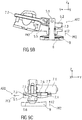
- Figure 10 shows schematically in an exploded view an exemplary embodiment for a triggering mechanism 7, which is triggered in the event of a collision, in the form of a pyrotechnic propellant 7.4, around the locking mechanism 5 to be triggered automatically and put in a locking position or locked position E2.
- the pyrotechnic propellant charge 7.4 is designed as a pyrotechnic actuator which drives a piston 7.6, which moves the locking bolt 5.1 indirectly via the wedge element 7.3 cooperating with the adjustment element 5.2, in particular lifts it.
- the wedge element 7.3 is moved according to arrow PF3, as a result of which the adjusting element 5.2 and with it the locking bolt 5.1 is moved according to arrow PF2.
- the pyrotechnic propellant charge 7.4 can optionally be surrounded by a sleeve 7.7, in particular a protective sleeve.
- the advantage of the described release mechanism 7 with a separate release unit in normal operation and a separate release unit in the event of a collision is, in particular, that in normal operation the seat shell 4 can be pivoted, in particular moved, or locked by means of just one operation, in particular a one-button / one-button operation and in the event of a collision, the seat shell 4 can be automatically locked against movement in the millisecond range by means of the pyrotechnic propellant 7.4.
- the release mechanism 7 can be activated, for example, by means of a simple switch, a touch or gesture sensor, and the adjustment mechanism 6 can be unlocked or locked. This increases the ease of use.
- the floating seat 1 due to the articulated mounting of the seat shell 4 on the base element 2, the floating seat 1 has a high level of seating and adjustment comfort in the form of a floating state when the seat is adjusted.
- Figure 11 shows a schematic sectional view of a locking mechanism 5 in operative connection with part of a braking unit 14 for braking and / or locking the movement of a floating seat 1 in the XZ direction.
- the brake unit 14 comprises, as described above, the locking bolt 5.1, which can be adjusted in the vertical direction Z between an unlocked position E1 and a locked position E2 (arrow PF 2) by means of the adjusting element 5.2 (arrow PF1) movable in the longitudinal direction X.
- the locking mechanism 5 is designed in particular in normal operation as a continuous or stepless locking or arresting device.
- the locking mechanism 5 has, for example, an electromechanical drive unit, such as the servomotor 7.1, which interacts with the wedge brake unit 13, as will be described in more detail below.
- the electromechanical drive unit is designed in combination with the wedge brake unit 13 to at least brake and / or stop an adjustment, in particular inclination of the seat shell 4 relative to the base element 2 about the longitudinal, transverse and / or vertical axis X0, Y0 or Z0 .
- the adjustment mechanism 6 with the locking mechanism 5 is arranged on a seat plate 16 of the seat shell 4.
- a support element 15 for the seat plate 16 and a support element 17 for the servomotor 7.1 can be provided.
- the electromechanical drive unit is designed as a motor-gear unit, for example a drive or servomotor in combination with a spindle drive.
- Figure 12 shows a schematic sectional view of the locking mechanism 5 in operative connection with a part of the brake unit 14, in particular the wedge brake unit 13 for braking the movement, in particular the inclination of the floating seat 1.
- the wedge brake unit 13 is designed as a friction brake and is formed, for example, by the shape and / or material of surfaces of the base element 2 and of the braking element 9 that lie against one another.
- the surface 2.2 of the base element 2 facing the braking element 9 is made of a particularly hard material with a high modulus of elasticity, in particular in a range of 5,000 MPa (pressure hardness according to Rockwell, DIN 2039-1), and the surface facing the base element 2 9.1 of the braking element 9 made of a soft material with a lower modulus of elasticity of approximately 70 +/- 10 Shore-A (according to DIN 53505) and high elasticity, or vice versa.
- the base element 2 is made of polyamide and the braking element 9 is made of ethylene-propylene-diene rubber (called EPDM for short).
- EPDM ethylene-propylene-diene rubber
- at least one of the surfaces 2.2 or 9.1 can be roughened.
- that surface 2.2 or 9.1, which is formed from a harder material is roughened.
- the surface 2.2 is provided with a surface profile or a surface structure between 0.2 mm and 0.8 mm deep.
- Both the base element 2 and the braking element 9 can also be formed from a hard material, one of these elements being provided with a soft or flexible coating and / or a corresponding deep surface structure as a braking layer.
- the wedge brake unit 13 comprises, for example, opposing braking, wedge and / or friction surfaces.
- a braking surface for example surface 9.1
- a braking surface has a spherical shape, which slides in a damped manner on a braking, sliding or guiding surface inclined in the opposite direction, for example surface 2.2, and thereby brakes and stops until no more relative movements occur and thus locks.
- one of the surfaces 2.2 or 9.1 or both can be provided with a braking layer (for example made of a softer material) and / or a braking profile (roughening).
- Figure 13 shows schematically in an exploded view components such as a servomotor 7.1 with threaded rod 7.2, a wedge or adjustment element 7.3, 5.2, a slider or slide 5.3, a locking bolt 5.1, a bearing or base element 5.5 for the locking bolt 5.1, a braking element 9, a fastening element 8 and a seat plate 16, a support element 15 for the seat plate 16 and a support element 17 for the servomotor 7.1 of a combined locking and adjustment mechanism 5, 6 with an integrated wedge brake unit 13 for a floating seat 1.
- screws 18 washers 19 and Nuts 27 are provided.
- the threaded rod 7.2 is held by means of a pin 21 on the wedge or adjustment element 7.3, 5.2.
- the adjusting element 5.2 has a corresponding pin opening 24 for this purpose.
- the carriages 5.3 are held on the locking bolt 5.1 by means of a pin 22.
- the locking bolt 5.1 has a corresponding pin opening 23 for this purpose.
- locking bolt 5.1 can be provided with slots 25 for receiving keys 26.
Landscapes
- Engineering & Computer Science (AREA)
- Aviation & Aerospace Engineering (AREA)
- Transportation (AREA)
- Mechanical Engineering (AREA)
- Seats For Vehicles (AREA)
Description
- Die Erfindung betrifft einen Schwebesitz, insbesondere verriegelbarer Schwebesitz für ein Fahrzeug, insbesondere einen relativ zu einem Karosserieboden neigbaren Fahrzeugsitz.
- Im Stand der Technik sind Schwebesitze (auch floating seat genannt) bekannt (siehe z.B.
ES-A-2 184 564 - Aufgabe der vorliegenden Erfindung ist es, einen Schwebesitz mit verbessertem Komfort und besserer Sicherheit anzugeben.
- Die Aufgabe wird erfindungsgemäß gelöst mit einem Schwebesitz, umfassend ein Basis- oder Trägerelement und eine Sitzschale, wobei zwischen Sitzschale und Basiselement ein Verstellmechanismus in Art eines Gelenk- oder Gleitlagers, insbesondere eines Kugelgelenk- oder Schalengleitlagers, ausgebildet ist, wobei die Sitzschale mittels des Verstellmechanismus in zumindest zwei oder allen drei Rotationsfreiheitsgraden relativ zum Basiselement verstellbar ist.
- Die Aufgabe wird erfindungsgemäß gelöst mit einem Schwebesitz, umfassend ein Basis- oder Trägerelement, ein Adapterelement und eine Sitzschale, wobei zumindest zwischen Sitzschale und Adapterelement und/oder zwischen Adapterelement und Basiselement jeweils ein Verstellmechanismus in Art eines Gelenk- oder Gleitlagers, insbesondere eines Kugelgelenk- oder Schalengleit- oder Mehrgleitflächenlagers, gebildet ist, wobei die Sitzschale mittels des Verstellmechanismus in zumindest zwei oder in allen drei Rotationsfreiheitsgraden relativ zum Basiselement verstellbar ist.
- Ein Aspekt sieht vor, dass die Sitzschale mittels des Verstellmechanismus relativ zum Basiselement zumindest um eine Querachse neigbar und um eine Hochachse drehbar ist.
- In einer möglichen Ausführungsform ist die Sitzschale relativ zum Basiselement in Längsrichtung um eine Querachse in einem Bereich zwischen 0° und 120° neigbar und/oder in Querrichtung um eine Längsachse in einem Bereich zwischen 0° und 5° neig- oder rollbar und/oder um eine Hochachse des Schwebesitzes maximal bis zu 20° dreh- oder schwenkbar. Beispielsweise nimmt die Sitzschale in einer Design- oder Sitzposition eine Stellung ein, in welcher die Sitzschale in Längsrichtung nach vorne und somit in Fahrt-/Sichtrichtung ausgerichtet ist. Diese Stellung wird auch als 0°-Position in Bezug auf die Hochachse (Z-Achse) und Längsachse (X-Achse) bezeichnet. In dieser Design- oder Sitzposition ist die Sitzschale zum verbesserten Sitzkomfort um die Querachse (Y-Achse) beispielsweise 25° nach hinten geneigt. Die Sitzschale ist mittels des Gleitlagers gegenüber der Design- oder Sitzposition beispielsweise um die Querachse bis zu 10° nach vorne und bis zu 20° nach hinten neigbar. Maximal ist die Sitzschale um die Querachse bis zu 120° neigbar. Um die Hochachse ist die Sitzschale insbesondere maximal bis zu 280° drehbar, insbesondere um -90° bis zu +190° in Bezug auf die Design- oder Sitzposition drehbar.
- In einer möglichen Ausführungsform ist das Gleitlager als ein Schalengleitlager oder Mehrgleitflächenlager ausgebildet. Beispielsweise umfasst das Gleitlager mehrere separate Gleitflächen, die derart angeordnet und/oder geformt sind, dass ein kugelschalenförmiges Gleitlager zwischen Basiselement und Sitzschale gebildet ist. Dabei umfasst beispielsweise das Basiselement mehrere partielle Gleitflächen, die kugelschalenförmig geformt und verteilt am Basiselement angeordnet sind. Die Sitzschale weist eine einzelne oder mehrere, zu diesen partiellen Gleitflächen korrespondierende, kugelschalenförmige Gleitfläche/n auf. Alternativ können Basiselement und Sitzschale jeweils eine einzelne Gleitfläche aufweisen, die zueinander korrespondierend, beispielsweise kugelschalenförmig, ausgebildet sind.
- Die Sitzschale ist somit im entriegelten Zustand in mehreren Freiheitsgraden, insbesondere in allen Rotationsfreiheitsgraden bewegbar, insbesondere schwenk- oder neigbar. Im verriegelten Zustand ist die Sitzschale blockiert.
- Die Aufgabe wird erfindungsgemäß mit einem Schwebesitz gelöst, umfassend ein Basis- oder Trägerelement, ein optionales Adapterelement und eine Sitzschale, wobei ein Verriegelungsmechanismus zur Ver- und/oder Entriegelung einer Verstellung der Sitzschale relativ zum Basiselement vorgesehen ist, wobei der Verriegelungsmechanismus mittels eines Auslösemechanismus betätigbar ist, und wobei der Auslösemechanismus eingerichtet ist, den Verriegelungsmechanismus im Normalbetrieb zur Ent- oder Verriegelung der Verstellung der Sitzschale relativ zum Basiselement manuell oder elektrisch zu betätigen und optional oder zusätzlich im Kollisionsfall automatisch zu betätigen, um die Verstellung der Sitzschale relativ zum Basiselement automatisch zu verriegeln.
- Der Verriegelungsmechanismus ist insbesondere im Normalbetrieb als eine kontinuierliche oder stufenlose Verriegelung oder Arretierung ausgebildet.
- Insbesondere ist der Verriegelungsmechanismus im Normalbetrieb mittels des Auslösemechanismus kontinuierlich oder stufenlos, beispielsweise mittels eines elektrischen Motors, betätigbar, insbesondere zwischen einer entriegelten Stellung und einer verriegelten Stellung oder umgekehrt bewegbar.
- Hierzu weist der Verriegelungsmechanismus beispielsweise eine elektromechanische Antriebseinheit auf, die mit einer Bremseinheit, beispielsweise einer Keilbremseinheit, zusammenwirkt. Dabei ist die elektromechanische Antriebseinheit ausgebildet, eine Verstellung der Sitzschale relativ zum Basiselement in Längs- und in Hochrichtung zu bremsen und/oder zu ver- oder zu entriegeln. Die Brems-, insbesondere eine Keilbremseinheit, ist eingerichtet, eine Verstellung der Sitzschale relativ zum Basiselement in Quer- und in Hochrichtung zu bremsen und/oder zu stoppen, insbesondere zu ver- oder zu entriegeln.
- In einer möglichen Ausführungsform ist die elektromechanische Antriebseinheit als eine Motor-Getriebe-Einheit, beispielsweise ein Antriebsmotor in Kombination mit einem Spindelantrieb, ausgebildet.
- Die Bremseinheit umfasst beispielsweise gegenläufige Brems-, Keil- und/oder Reibflächen. Beispielsweise weist eine Bremsfläche eine sphärische Form auf, welche auf eine dazu gegenläufig geneigte Brems-, Gleit- oder Führungsfläche gleitet und dadurch abbremst.
- Im Kollisionsfall ist der Verriegelungsmechanismus mittels des Auslösemechanismus automatisch sowie kontinuierlich oder stufenlos, beispielsweise mittels eines pyrotechnischen Treibsatzes, betätigbar, insbesondere in eine verriegelte Stellung bewegbar.
- Der Schwebesitz ist derart ausgebildet, dass eine Position der Sitzschale relativ zum Basiselement in mindestens zwei oder mehreren Freiheitsgraden, insbesondere in mindestens einem oder mehreren Translationsfreiheitsgrad/en, wie beispielsweise in Hochrichtung oder Längsrichtung, und/oder in mindestens einem oder mehreren Rotationsfreiheitsgrad/en, beispielsweise in vertikale Drehrichtung oder horizontale Drehrichtung um eine Hoch-, Längs- und/oder Querachse, einstellbar ist. Dazu ist beispielsweise ein Verstellmechanismus vorgesehen. Durch die Einstellung der Position der Sitzschale in mehr als zwei Freiheitsgraden, insbesondere Rotationsfreiheitsgraden, wird der Eindruck einer schwebenden oder gleitenden Sitzschale erzeugt, welche einer Bewegung eines Benutzers auf dem Sitz folgt. Der Verstellmechanismus ist beispielsweise in Art eines Gelenk- oder Gleitlagers, insbesondere eines Kugelgelenks oder Kugellagers, ausgebildet. Beispielsweise weist das Gelenk- oder Gleitlager eine sphärische Gleitfläche auf, in welcher eine sphärische Lauffläche gleitet. Dabei ist die sphärische Gleitfläche am Basiselement in Richtung der Sitzschale ausgebildet, wobei die Sitzschale selbst und/oder das Adapterelement eine zu der sphärischen Gleitfläche am Basiselement korrespondierende Lauffläche aufweist oder umgekehrt.
- Beispielsweise weist die sphärische Gleitfläche eine konkave Form und die sphärische Lauffläche eine dazu korrespondierende konvexe Form auf.
- Auch kann das Gelenk- oder Gleitlager als ein Pendel- oder Schalengleitlager ausgebildet sein. Dabei weist das Pendellager beispielsweise eine Pendel- oder Schwing- oder Gleitschale oder Gelenkpfanne auf, in welcher ein Gelenkkopf oder eine kugelförmige Schale gleitet. Die Sitzschale ist somit im entriegelten Zustand in mehreren Freiheitsgraden bewegbar, insbesondere schwenk- oder neigbar. Im verriegelten Zustand ist die Sitzschale blockiert.
- Der Verriegelungsmechanismus ist insbesondere als eine mechanische Verbindung, beispielsweise eine Rastverbindung, eine Steckverbindung oder eine andere geeignete Formschluss- oder Kraftschluss-, insbesondere Reibschlussverbindung, ausgebildet. Beispielsweise ist der Verriegelungs- und/oder Bremsmechanismus als eine Steck- und/oder Rastverbindung ausgebildet. Der Verriegelungs- und/oder Bremsmechanismus kann alternativ oder zusätzlich als eine Kraft-, insbesondere Reibschlussverbindung ausgebildet sein.
- In einer möglichen Ausführungsform umfasst der Auslösemechanismus einen Elektromotor oder Stellmotor zur elektrischen Betätigung des Verriegelungsmechanismus des Sitzes. Gemäß einem weiteren Aspekt treibt der Elektromotor zur Betätigung des Verriegelungsmechanismus direkt ein Verriegelungselement oder indirekt über eine Gewindestange das Verriegelungselement an, welcher beispielsweise als ein Schlitten, insbesondere eine Keil- oder Rastplatte, ausgebildet ist, so dass dieses Verriegelungselement je nach Bewegungsrichtung in einen oder aus einem Verriegelungseingriff gelangt.
- In einer weiteren Ausführungsform umfasst der Auslösemechanismus einen pyrotechnischen Treibsatz, um den Verriegelungsmechanismus automatisch auszulösen und in eine Verriegelungsposition zu stellen.
- In einer Weiterbildung ist der pyrotechnische Treibsatz als ein pyrotechnischer Aktuator ausgebildet, der einen Kolben vortreibt, welcher ein Verriegelungselement, insbesondere eine Keil- oder Rastplatte, bewegt, so dass dieses Verriegelungselement in eine Verriegelungsposition gestellt ist.
- Die mit der Erfindung erzielten Vorteile bestehen insbesondere darin, dass im Normalbetrieb mittels nur einer Bedienung die Sitzschale schwenkbar, insbesondere bewegbar ist, und im Kollisionsfall die Sitzschale im Millisekundenbereich gegen Bewegung verriegelbar ist.
- Ausführungsbeispiele der Erfindung werden anhand von Zeichnungen näher erläutert. Dabei zeigen:
- Figuren 1A und 1B
- schematisch in verschiedenen perspektivischen Darstellungen einen Schwenk- oder Schwebesitz,
- Fig. 1C bis 1E
- schematisch in perspektivischer Darstellung eine Ausführungsform für einen Schwebesitz ohne Polsterung mit kugelschalenförmiger Sitzschale und einem Adapterelement mit mehreren Gleitflächen,
- Figur 2
- schematisch in Schnittdarstellung einen Verstellmechanismus in Art eines Gelenklagers, insbesondere eines Kugelgelenk- oder Gleitlagers für einen Schwenk- oder Schwebesitz,
- Figuren 3 bis 5
- schematisch in perspektivischer Darstellung einen Schwenk- oder Schwebesitz in verschiedenen Positionen und mit verschiedenen einstellbaren Freiheitsgraden,
- Figur 6
- schematisch in Explosionsdarstellung einen Schwenk- oder Schwebesitz,
- Figuren 7A bis 7C
- schematisch in perspektivischer Darstellung einen Verriegelungsmechanismus für einen Schwenk- oder Schwebesitz im Normalbetrieb in entriegelter Stellung,
- Figuren 8A bis 8C
- schematisch in perspektivischer Darstellung und teilweise aufgeschnittener Darstellung einen Verriegelungsmechanismus für einen Schwenk- oder Schwebesitz in entriegelter Stellung und mit einem Auslösemechanismus, umfassend einen pyrotechnischen Treibsatz für eine automatische Auslösung des Verriegelungsmechanismus in einem Kollisionsfall,
- Figuren 9A bis 9D
- schematisch in perspektivischer und teilweise aufgeschnittener Darstellung einen Verriegelungsmechanismus für einen Schwenk- oder Schwebesitz in einer durch einen Kollisionsfall ausgelösten verriegelten Stellung,
- Figur 10
- schematisch in Explosionsdarstellung ein Ausführungsbeispiel für einen pyrotechnischen Treibsatz mit Kolben für einen Auslösemechanismus,
- Figur 11
- schematisch in Z-X-Schnittdarstellung einen Verriegelungsmechanismus in Wirkzusammenhang mit einem Teil einer Bremseinheit zum Bremsen und/oder Verriegeln der Bewegung eines Schwebesitzes,
- Figur 12
- schematisch in Z-Y-Schnittdarstellung einen Verriegelungsmechanismus in Wirkzusammenhang mit einem Teil einer Bremseinheit zum Bremsen und/oder Verriegeln der Bewegung eines Schwebesitzes, und
- Figur 13
- schematisch in Explosionsdarstellung Komponenten eines kombinierten Verstell- und Verriegelungsmechanismus mit integrierter Keilbremseinheit für einen Schwebesitz.
- Einander entsprechende Teile sind in allen Figuren mit den gleichen Bezugszeichen versehen.
-
Figuren 1A und1B zeigen schematisch in zwei perspektivischen Darstellungen eine von schräg vorne und eine von schräg hinten einen Schwenk- oder Schwebesitz 1, insbesondere einen Fahrzeugsitz, der insbesondere in mehreren Freiheitsgraden F1 bis F3 bewegbar, insbesondere schwenk-, dreh- und/oder neigbar ist. Der Schwebesitz 1 ist insbesondere in einem Fahrzeug vorgesehen und dort an einem Fahrzeugboden in nicht näher dargestellter Art und Weise befestigt. - Der Schwebesitz 1 umfasst zumindest ein Träger- oder Basiselement 2, ein optionales Adapterelement 3 und eine Sitzschale 4 (
Figur 1B ). Anstelle des optionalen Adapterelements 3 kann die Sitzschale 4 entsprechend geformt und ausgebildet sein und direkt am Basiselement 2 angeordnet und gelagert sein (Figur 1A ). In einer weiteren Alternative (nicht dargestellt) kann das Adapterelement 3 Teil des Bodens der Sitzschale 4 sein. - Die Sitzschale 4 kann darüber hinaus einstückig aus einem Sitzteil 4.1 und einer Sitzlehne 4.2 gebildet sein. Alternativ kann die Sitzschale 4 aus einem separaten Sitzteil 4.1 und einer an diesem neigbar angeordneten Sitzlehne 4.2 gebildet sein (nicht näher dargestellt). Die Sitzschale 4 kann ferner aus einem Träger 4.3, insbesondere einer Hartschaumschale oder Verbundstoff-Schale, insbesondere aus einem faserverstärktem Kunststoff, und einem auf diesem angeordnetem Polsterelement 4.4, insbesondere einem Schaumpolster mit oder ohne Bezug, gebildet sein.
- Zwischen Sitzschale 4 und Basiselement 2 (
Figur 1A ) und/oder zwischen Adapterelement 3 und Basiselement 2 (Figur 1B ) ist jeweils ein Verstellmechanismus 6 in Art eines Gelenk- oder Gleitlagers G ausgebildet. Damit ist die Sitzschale 4 direkt bzw. indirekt über das Adapterelement 3 gleitend, insbesondere neig-, dreh- und/oder schwenkbar, am Basiselement 2 gelagert. Mittels des Verstellmechanismus 6 ist die Sitzschale 4 relativ zum Basiselement 2 zur Verstellung V in zumindest zwei oder allen drei Rotationsfreiheitsgraden R1, R2 und/oder R3 gleitend gelagert. - Beispielsweise nimmt die Sitzschale 4 in einer Design- oder Sitzposition P1 eine Stellung ein, in welcher die Sitzschale 4 in Längsrichtung X nach vorne und somit in Fahrt-/Sichtrichtung ausgerichtet ist. Diese Sitzposition P1 wird auch als 0°-Position in Bezug auf die Hochachse Z0 und Längsachse X0 bezeichnet. In dieser Sitzposition P1 ist die Sitzschale 4 zum verbesserten Sitzkomfort um die Querachse Y0 beispielsweise um 25° nach hinten geneigt. Dabei ist das Gleitlager G derart eingerichtet, dass die Sitzschale 4 gegenüber der Design- oder Sitzposition P1 beispielsweise um die Querachse Y0 bis zu 10° nach vorne und bis zu 20° nach hinten neigbar ist und maximal bis zu 120° nach hinten neigbar und/oder um die Hochachse Z0 insbesondere maximal bis zu 280° drehbar, insbesondere um -90° bis zu +190° drehbar.
- Der Verstellmechanismus 6 ist beispielsweise in Art eines Schalengleitlagers 6.1 ausgebildet. Auch kann der Verstellmechanismus 6 in Art eines Kugelgelenks ausgebildet sein.
- In einer weiteren Ausführungsform des Schwebesitzes 1 umfasst dieser ein Träger- oder Basiselement 2, ein Adapterelement 3 und eine Sitzschale 4, wobei zumindest zwischen Sitzschale 4 und Adapterelement 3 sowie zwischen Adapterelement 3 und Basiselement 2 jeweils ein Verstellmechanismus 6 in Art eines Gleitlagers G, insbesondere eines Kugelgelenks oder Schalengleitlagers, gebildet und die Sitzschale 4 mittels eines solchen mehrfachen Verstellmechanismus 6 in zumindest zwei oder allen drei Rotationsfreiheitsgraden R1, R2 und/oder R3 relativ zum Basiselement 2 verstellbar ist (nicht näher dargestellt).
- Beispielsweise ist die Sitzschale 4 relativ zum Basiselement 2 um eine Querachse Y0 von einer Normalstellung in eine Komfortstellung in einem Bereich zwischen 0° und 120° neigbar und/oder um eine Längsachse X0 in einem Bereich zwischen 0° und 5° neigbar und/oder um eine Hochachse Z0 maximal bis zu 20° drehbar.
- Mit anderen Worten: Der Schwebesitz 1 ist derart ausgebildet, dass eine Position der Sitzschale 4 relativ zum Basiselement 2 in mindestens zwei oder mehreren Freiheitsgraden F1 bis F3, insbesondere in mindestens einem oder mehreren Translationsfreiheitsgraden T1, T2, wie beispielsweise in Hochrichtung Z und/oder Längsrichtung X, und/oder in mindestens einem oder mehreren der Rotationsfreiheitsgrade R1, R2, R3 einstellbar ist. Dazu ist der Verstellmechanismus 6 vorgesehen. Durch die Einstellung der Position der Sitzschale 4 in mehr als zwei Freiheitsgraden F1 bis F3 wird der Eindruck einer schwebenden oder gleitenden Sitzschale 4 erzeugt, welche einer Bewegung eines Benutzers auf dem Schwebesitz 1 folgt.
- Zur Verriegelung der Sitzschale 4 in einer eingestellten Position ist ein Verriegelungsmechanismus 5 vorgesehen, der die Sitzschale 4 in der eingestellten Position relativ zum Basiselement 2 fixiert. Der Verriegelungsmechanismus 5 wird nachfolgend anhand von Beispielen näher beschrieben. In einer möglichen Ausführungsform kann der Verriegelungsmechanismus 5 im Adapterelement 3 angeordnet sein.
- Beispielsweise umfasst der Verriegelungsmechanismus 5 eine elektromechanische Antriebseinheit 12, die mit einer Bremseinheit 14 zusammenwirkt, die zwischen Sitzschale 4 und Basiselement 2 eingreift.
-
Figuren 1C bis 1E zeigen schematisch in perspektivischer Darstellung eine weitere beispielhafte Ausführungsform für einen Schwebesitz 100, eine Polsterung mit einer Sitzschale 40 und einem Adapterelement 30 zwischen denen ein Mehrgleitflächenlager 61 als Verstellmechanismus 60 (dargestellt inFigur 1C ) ausgebildet ist. - Die weiteren, in
Figuren 1C bis 1E nicht näher gezeigten, Komponenten zur variablen Verstellung des Schwebesitzes 100 relativ zu einem Fahrzeugboden in mindestens zwei Rotationsfreiheitsgraden R1 bis R3, wie Basiselement 2, Verriegelungsmechanismus 5, Antriebseinheit 12, Bremseinheit 14, entsprechen den in denFiguren 1A bis 1B und2 bis 11 dargestellten und vorgehend oder nachfolgend entsprechend beschriebenen Komponenten. - Das Adapterelement 30 ist mittels Befestigungsbolzen 35 und/oder Befestigungsflanschen 36 am Basiselement 20, insbesondere an einem seitlichen Sitzrahmen 37 befestigt.
-
Figuren 1C und1D zeigen die Sitzschale 40 mit einem Sitzteil 41, welches in Richtung des Adapterelements 30 eine kugelschalenförmige Gleitfläche 41.1 aufweist. Die Gleitfläche 41.1 ist kugelschalenförmig ausgebildet. Beispielsweise kann die Gleitfläche 41.1 in mehrere Teilgleitflächen unterteilt sein. Alternativ kann diese als eine einzelne konkav geformte Fläche oder eine konkav geformte Oberfläche mit mehreren Teilgleitflächen ausgebildet sein. - Die Sitzschale 40 ist als eine einteilige Rahmenschale 42, insbesondere eine Spritzgussrahmenschale oder eine in einem anderen geeigneten Formverfahren hergestellte Schale, ausgebildet.
- Um sowohl eine variable Verstellung des Schwebesitzes 100 relativ zu einem Fahrzeugboden in mindestens zwei Rotationsfreiheitsgraden R1 bis R3 als auch eine hinreichende Sicherheit für einen Benutzer des Schwebesitzes 100 zu ermöglichen, sind an der Rahmenschale 42 selbst eine entsprechende Anzahl von Anbindungspunkten 43 für einen Sicherheitsgurt 44, beispielsweise von drei Anbindungspunkten 43 für einen Dreipunktgurt, angeordnet.
-
Figur 1E zeigt ein Ausführungsbeispiel für das Adapterelement 30. Das Adapterelement 30 weist eine konkave Oberflächenform 32 auf, welche in Richtung der Sitzschale 40, insbesondere des Sitzteils 41 weist. Die konkave Oberflächenform 32 weist mehrere Teilgleitflächen 33 auf. Die Teilgleitflächen 33 sind kugelschalenförmig oder konkav geformt. Die Teilgleitflächen 33 bilden Punktlagerungen für die korrespondierende Gleitfläche 41.1 des Sitzteils 41 oder deren, nicht dargestellten Teilgleitflächen. Die Teilgleitflächen 33 sind aus einem anderen Material, insbesondere einem geeigneten Gleitmaterial, wie zum Beispiel einem Kunststoff, Graphit, Carbon, EPDM, als das Material des Adapterelements 30 gefertigt. Das Gleitmaterial weist insbesondere einen geringen Gleitreibungskoeffizienten, eine hohe Verschleißfestigkeit und eine hohe mechanische Belastbarkeit sowie Formstabilität und Temperaturbeständigkeit auf. Auch können die einander gegenüberliegenden, das Gleitlager G bildenden Flächen - Teilgleitflächen 33 des Adapterelements 30 und Gleitfläche 41.1 der Sitzschale 40 - aus verschiedenen Materialien gebildet sein. Beispielsweise ist eines der Flächen aus einem besonders harten Material mit hohen E-Modul und das andere aus einem weichen Material mit geringem E-Modul gebildet. - Die Teilgleitflächen 33 sind voneinander beabstandet auf dem Adapterelement 30 in Richtung der Sitzschale 40 weisend aufgebracht.
- Zusätzlich weist das Adapterelement 30 eine Ausnehmung 34 auf, durch welche die Bremseinheit 14 und der Verriegelungsmechanismus 5 zum Bremsen der Bewegung der Sitzschale 40 relativ zum Adapterelement 30 bis hin zum Verriegeln von Sitzschale 40 und Adapterelement 30 und somit der Bewegung bzw. Positionierung des Schwebesitzes 100 relativ zum Basiselement 20 in einer eingestellten Position eingreift. Die Bremseinheit 14 und der Verriegelungsmechanismus 5 werden nachfolgend näher beschrieben.
-
Figur 2 zeigt schematisch in Schnittdarstellung ein Ausführungsbeispiel für einen Verstellmechanismus 6 in Art eines Gleitlagers G mit einem Schalengleitlager 6.1 für den Schwenk- oder Schwebesitz 1. Der Schwebesitz 1 umfasst das Basiselement 2 zur Befestigung an einer Karosserie in einem Fahrzeug. - Zur Ver- oder Entriegelung des Verstellmechanismus 6 und damit der Verstellung des Schwebesitzes 1 umfasst dieser einen Verriegelungsmechanismus 5.
- Das Basiselement 2 ist derart ausgestaltet, dass es weitere herkömmliche Funktionselemente, wie eine Längsverstelleinheit 10 und/oder eine Höhenverstelleinheit 11 mit einer zugehörigen Antriebseinheit 12, zur Verstellung des Schwebesitzes 1 in einen oder mehreren Translationsfreiheitsgraden T1 und T2 in Längsrichtung X bzw. Hochrichtung Z aufnehmen kann.
- Beispielsweise weist das Gleit- oder Gelenklager G eine sphärische Gleitfläche 2.1 auf, in welcher eine sphärische Lauffläche 3.1 gleitet.
- Dabei ist die sphärische Gleitfläche 2.1 am Basiselement 2 in Richtung der Sitzschale 4 ausgebildet. Im gezeigten Ausführungsbeispiel ist die sphärische Gegen- oder Lauffläche 3.1 am Adapterelement 3 ausgebildet.
- Alternativ kann die Sitzschale 4 selbst eine zu der sphärischen Gleitfläche 2.1 des Basiselements 2 korrespondierende Lauffläche aufweisen. Beispielsweise weist die sphärische Gleitfläche 2.1 eine konkave Form und die sphärische Lauffläche 3.1 eine dazu korrespondierende konvexe Form auf.
- Auch kann das Schalengleitlager 6.1 als ein Gelenklager G, ein Kugelgelenk oder ein Pendellager ausgebildet sein. Dabei weist das Pendellager beispielsweise eine Pendel- oder Schwingschale oder Gelenkpfanne auf, in welcher ein Gelenkkopf oder eine kugelförmige Schale abwälzt.
- Die Sitzschale 4 ist im entriegelten Zustand des Verriegelungsmechanismus 5 relativ zum Basiselement 2 in mehreren Freiheitsgraden F1 bis F3, insbesondere in allen Rotationsfreiheitsgraden R1 bis R3 bewegbar, insbesondere schwenk- oder neigbar. Im verriegelten Zustand ist die Sitzschale 4 gegenüber dem Basiselement 2 blockiert und nicht verstellbar.
-
Figuren 3 bis 5 zeigen schematisch in perspektivischer Darstellung den Schwebesitz 1 in verschiedenen Positionen P1 bis P3 und mit verschiedenen einstellbaren Freiheitsgraden F1 bis F3, insbesondere den Rotationsfreiheitsgraden R1 bis R3. - Der Schwebesitz 1 kann beispielsweise in mindestens einem oder mehreren Translationsfreiheitsgraden T1, T2, wie beispielsweise in Hochrichtung Z, in Längsrichtung X oder in Querrichtung Y, und/oder in mindestens einem oder mehreren Rotationsfreiheitsgraden R1 bis R3, beispielsweise in vertikale Drehrichtung oder horizontale Drehrichtung um eine Hoch-, Längs- und/oder Querachse, einstellbar sein. Dazu ist beispielsweise der Verstellmechanismus 6 vorgesehen. Durch die Einstellung einer der Positionen P1 bis P3 der Sitzschale 4 in mehr als zwei Freiheitsgraden F1 bis F3, insbesondere Rotationsgraden R1 bis R3, wird der Eindruck einer schwebenden Sitzschale 4 erzeugt, welche einer Bewegung eines Benutzers auf dem Schwebesitz 1 folgt.
-
Figur 3 zeigt den Schwebesitz 1 in einer leicht in Längsrichtung X nach hinten geneigten oder geschwenkten Position P1, in welcher die Sitzschale 4 um die Querachse Y0 zwischen einer Normalstellung und einer Komfortstellung, insbesondere einer Sitz- oder Liegekomfortstellung, in einem Bereich von 0° bis maximal 180° gegenüber der Normalstellung, insbesondere einer weitgehend senkrechten Stellung der Sitzlehne 4.2, geneigt werden kann. -
Figur 4 zeigt den Schwebesitz 1 in einer um eine Hochachse Z0 gedrehten Position P2 gegenüber einer Normalstellung, in welcher der Schwebesitz 1 beispielsweise in einem Fahrzeug in Fahrtrichtung ausgerichtet ist. Dabei ist der Verstellmechanismus 6 eingerichtet, den Schwebesitz 1 zwischen der Normalstellung und einer gedrehten Stellung in einem Bereich bis zu maximal 20° zu drehen oder zu schwenken. -
Figur 5 zeigt den Schwebesitz 1 in einer leicht zur Seite um die Längsachse X0 geneigten oder geschwenkten Position P3, in welcher die Sitzschale 4 um die Längsachse X0 zwischen einer Normalstellung und einer zur Seite geneigten Stellung in einem Bereich bis zu maximal 5° gegenüber der Normalstellung, insbesondere einer weitgehend waagerechten Stellung des Sitzteils 4.1, geneigt oder gerollt werden kann. -
Figur 6 zeigt schematisch in Explosionsdarstellung den Schwenk- oder Schwebesitz 1, umfassend zumindest das Basiselement 2, das Adapterelement 3 und die Sitzschale 4. Zwischen dem Basiselement 2 und dem Adapterelement 3 ist der Verriegelungsmechanismus 5 mit integrierter Bremseinheit 14 angeordnet. Die Bremseinheit 14 ist beispielsweise als eine Keilbremseinheit 13 ausgebildet, die ein Bremselement 9, insbesondere eine Bremsschale oder -platte, umfassen kann. - Der Verriegelungsmechanismus 5 ist mittels eines Auslösemechanismus 7 (dargestellt in
Figuren 7A bis 10 ) betätigbar, insbesondere ver- oder entriegelbar. Dabei kann der Auslösemechanismus 7 beispielsweise für einen normale Verstellung der Sitzschale 4 durch einen Benutzer und somit im Normalbetrieb elektrisch ausgebildet sein und einen Stellmotor 7.1 umfassen (dargestellt inFiguren 7A bis 7C ). Für eine automatische Verriegelung der Sitzschale 4 in einem Kollisionsfall des Fahrzeugs umfasst der Auslösemechanismus 7 zusätzlich einen pyrotechnischen Treibsatz 7.4, mittels welchen die Sitzschale 4 automatisch innerhalb von wenigen Millisekunden, insbesondere weniger als 10 ms, gegen eine Bewegung verriegelt wird (dargestellt in denFiguren 8A bis 10 ). - Beispielsweise ist der Auslösemechanismus 7 in Wirkzusammenhang mit dem Verriegelungsmechanismus 5 eingerichtet, im Normalbetrieb eine Verstellung der Sitzschale 4 elektrisch zu ver- oder entriegeln (beispielhaft dargestellt in
Figuren 7A bis 7C ) und optional im Kollisionsfall die Verstellung der Sitzschale 4 reversibel zu verriegeln (beispielhaft dargestellt inFiguren 8A bis 10 ). - Mittels des Verriegelungsmechanismus 5 ist die Sitzschale 4, insbesondere deren Verstellmechanismus 6, vom Basiselement 2 entkoppelbar und gegen eine Verstellung relativ zum Basiselement 2 blockiert oder fixiert.
- Zur Befestigung des Verstellmechanismus 6 ist ein Befestigungselement 8, beispielsweise eine Befestigungsplatte oder -fuß, vorgesehen. Das Befestigungselement 8 ist im oder am Basiselement 2 befestigbar.
- Der Schwebesitz 1 ist beispielsweise derart ausgebildet, dass eine Position der Sitzschale 4 in mindestens zwei oder mehreren Freiheitsgraden F1 bis F3 einstellbar ist.
- Dabei kann der Schwebesitz 1 optional mit einem Schienensystem für eine Längsverstelleinheit 10 versehen sein, um beispielsweise in Längsrichtung X und damit in Translationsrichtung verstellt werden zu können.
- Der Verstellmechanismus 6 ist zur Verstellung der Sitzschale 4 in den Rotationsfreiheitsgraden R1 bis R3, beispielsweise in Art eines Schalengleitlagers 6.1 oder Gleit- oder Gelenklagers G ausgebildet. Beispielsweise weist das Schalengleitlager 6.1 eine sphärische Gleitfläche 6.2 auf, in welcher eine Lauffläche 6.3 gleitet. Dabei kann die sphärische Gleitfläche 6.2 am Basiselement 2 in Richtung der Sitzschale 4 ausgebildet sein, wobei die Sitzschale 4 selbst (nicht dargestellt) oder das Adapterelement 3 eine zu der sphärischen Gleitfläche 6.2 des Basiselements 2 korrespondierende Lauffläche 6.3 aufweist.
- Zusätzlich kann ein separates Bremselement 9, insbesondere eine Reib-/Bremsplatte- oder Reib-/Bremsschale oder Skateplatte, zwischen Adapterelement 3 und Basiselement 2 vorgesehen sein. Dabei kann das Bremselement 9 in Richtung des Adapterelements 3 eine Bremsfläche, die zu der Lauffläche 3.1 des Adapterelements 3 korrespondiert, und in Richtung des Basiselements 2 eine Lauffläche 6.3 aufweisen, die zu der Gleitfläche 2.1 des Basiselements 2 korrespondiert.
- In einer weiteren Ausführungsform kann das Gleitlager G und insbesondere das jeweilige Schalengleitlager 6.1 zwischen Basiselement 2 und Bremselement 9 sowie zwischen Bremselement 9 und Adapterelement 3 und zwischen Adapterelement 3 und Sitzschale 4 als ein Pendellager ausgebildet sein. Dabei weist das Pendellager beispielsweise eine Pendel- oder Schwingschale mit einer entsprechenden Gleitfläche 6.2 auf. Die Sitzschale ist somit im entriegelten Zustand in mehreren Freiheitsgraden F1 bis F3 bewegbar, insbesondere schwenk- oder neigbar. Im verriegelten Zustand ist die Sitzschale 4 und damit der Schwebesitz 1 blockiert.
-
Figur 7A zeigt schematisch in perspektivischer Darstellung ein Ausführungsbeispiel für einen Verriegelungsmechanismus 5 für einen Schwebesitz 1 im Normalbetrieb in entriegelter Stellung E1 mit einem elektrischen Auslösemechanismus 7 zur Betätigung des Verriegelungsmechanismus 5 im Normalbetrieb, insbesondere wenn ein Benutzer eine Verstellung des Schwebesitzes 1 wünscht. - Der Verriegelungsmechanismus 5 ist insbesondere als eine mechanische Verbindung, beispielsweise eine Rastverbindung, eine Steckverbindung oder eine andere geeignete Formschluss- oder Kraftschlussverbindung, ausgebildet.
- Beispielsweise umfasst der Verriegelungsmechanismus 5 ein Verriegelungselement, zum Beispiel einen Verriegelungsbolzen 5.1, der mittels eines Verstellelements 5.2 in eine verriegelte Stellung E2 stellbar ist oder gestellt wird. Hierzu ist der Verriegelungsbolzen 5.1 beispielsweise mittels eines Schlittens 5.3 auf dem Verstellelement 5.2 angeordnet und gelagert. Der Verriegelungsbolzen 5.1 ist beispielsweise mittels eines Stiftes am Schlitten 5.3 befestigt.
- Der Schlitten 5.3 ist auf einer Führungsfläche 5.4 des Verstellelements 5.2, insbesondere einem Keilelement oder einer Keilplatte, beweglich angeordnet. Das Verstellelement 5.2 ist auf einer, insbesondere schrägen oder keilförmigen Führungsfläche 5.7 eines Träger- oder Grundelements 5.5 beweglich angeordnet, insbesondere geführt, beispielsweise ziehbar (im Normalbetrieb) oder schiebbar (im Kollisionsfall) angeordnet.
-
Figur 7B zeigt die entriegelte Stellung E1 des Schwebesitzes 1, in welcher das Verstellelement 5.2 und damit der Verriegelungsbolzen 5.1 in eine untere entriegelte Stellung E1 gestellt sind, in welcher die Sitzschale 4 frei bewegt werden kann. Dabei sind das Verstellelement 5.2 und damit der Verriegelungsbolzen 5.1 in eine untere entriegelte Stellung E1 in Bezug auf das Basiselement 2 gestellt, in welcher das Bremselement 9 und die Sitzschale 4 freigegeben, beispielsweise voneinander entkoppelt sind und keinen Kontakt haben, und nicht damit verriegelt sind, so dass die Sitzschale 4 relativ zum Basiselement 2 frei bewegt werden kann. -
Figur 7C zeigt die verriegelte Stellung E2 des Schwebesitzes 1, in welcher das Verstellelement 5.2 und damit der Verriegelungsbolzen 5.1 in eine obere verriegelte Stellung E2 in Bezug auf das Basiselement 2 gestellt sind. Hierdurch sind das Bremselement 9 und die Sitzschale 4 relativ zum Basiselement 2 verriegelt, insbesondere mittels Reib- und Kraftschluss. Somit kann die Sitzschale 4 nicht frei bewegt werden. Zur Betätigung des Verriegelungsmechanismus 5, insbesondere des Verstellelements 5.2, im Normalbetrieb weist der Schwebesitz 1 einen Auslösemechanismus 7, insbesondere einen Stellmotor 7.1, auf. - Zur Verriegelung des Schwebesitzes 1 treibt der Stellmotor 7.1 eine Gewindestange 7.2, insbesondere eine Spindel, an, mittels welcher das Verstellelement 5.2, insbesondere eine Keilplatte, verstellt, beispielsweise in Richtung des Stellmotors 7.1 gemäß Pfeil PF1 von der entriegelten Stellung E1 in die verriegelte Stellung E2 bewegbar ist oder bewegt wird. Aufgrund einer Keilform 5.8 des Verstellelements 5.2 wird das Verriegelungselement, insbesondere der Verriegelungsbolzen 5.1 in die verriegelte Position oder Stellung E2 bewegt, insbesondere gehoben, wie dies anhand Pfeil PF2 gezeigt ist. Hierdurch werden das Befestigungselement 8 und das Bremselement 9 gehoben, sodass das Bremselement 9 und die Sitzschale 4 miteinander verriegelt sind und keine Relativbewegungen mehr möglich sind.
- Das Verstellelement 5.2 ist beispielsweise als ein Führungs- oder Bremselement 9, insbesondere ein Schlitten 5.3 oder eine Keil- oder Rastplatte oder ein Bremskissen oder Bremsklotz, ausgebildet. Das Verstellelement 5.2 ist gleitend auf dem Grundelement 5.5 des Verriegelungsmechanismus 5 angeordnet und relativ zu diesem verstellbar, insbesondere verschiebbar.
- Dabei kann das Verriegelungselement, wie der Verriegelungsbolzen 5.1, je nach Bewegungsrichtung gemäß Pfeil PF2 in einen oder aus einem Verriegelungseingriff in Bezug auf den Verstellmechanismus 6 und das Grundelement 5.5 und das Basiselement 2 gelangen.
-
Figuren 8A bis 8C zeigen schematisch in perspektivischer, in teilweise geschnittener in Längs- und in Querrichtung den Verriegelungsmechanismus 5 für den Schwebesitz 1 in entriegelter Stellung E1, in welcher der pyrotechnische Treibsatz 7.4 für die automatische Auslösung noch nicht ausgelöst hat. Damit ist ein Keilelement 7.3, das vom Treibsatz 7.4 in einem Kollisionsfall angetrieben wird, in einer Ausgangsstellung AS1 angeordnet. In dieser Ausgangsstellung AS1 ist das Keilelement 7.3 in einer Ebene mit der Führungsfläche 5.4, so dass das Verstellelement 5.2 und der Verriegelungsbolzen 5.1 in einer entriegelten Stellung E1 angeordnet sind. -
Figuren 9A bis 9D zeigen schematisch in perspektivischer Darstellung, in teilweise geschnittener in Längs- und in Querrichtung den Verriegelungsmechanismus 5 für den Schwebesitz 1 in verriegelter Stellung E2, in welcher der pyrotechnische Treibsatz 7.4 für die automatische Auslösung ausgelöst hat. Damit ist das Keilelement 7.3 vom aufgrund einer erkannten Kollision ausgelösten Treibsatz 7.4 angetrieben worden und in eine Auslösestellung AS2 gebracht worden. In dieser Auslösestellung AS2 ist das Keilelement 7.3 über die Ebene der Führungsfläche 5.4 hinausgehoben worden, so dass das Verstellelement 5.2 und der Verriegelungsbolzen 5.1 automatisch in die verriegelte Stellung E2 gebracht sind. -
Figur 9A zeigt schematisch in perspektivischer Darstellung den Verriegelungsmechanismus 5 für den Schwebesitz 1 in der aufgrund eines Kollisionsfalles verriegelten, insbesondere angehobenen Stellung E2, in welcher das Befestigungselement 8 und das Bremselement 9 angehoben sind und die Sitzschale 4 verriegelt ist. - Der Auslösemechanismus 7 umfasst zusätzlich zur Betätigung des Verriegelungsmechanismus 5 in einem Kollisionsfall das verstellbare Keilelement 7.3, das mittels des pyrotechnischen Treibsatzes 7.4 bei dessen Auslösung in einem Kollisionsfall in die Auslösestellung AS2 und damit in eine verriegelnde Position verstellbar ist. Das Keilelement 7.3 ist insbesondere zwischen dem Grundelement 5.5 des Verriegelungsmechanismus 5 und dem Verstellelement 5.2 für den Normalbetrieb angeordnet.
- Im Kollisionsfall wird das Keilelement 7.3 durch Auslösung des pyrotechnischen Treibsatzes 7.4 gemäß Pfeil PF3 verstellt, insbesondere vorgetrieben oder bewegt. Das Keilelement 7.3 weist mindestens eine Keilfläche 7.5 auf, welche auf eine hierzu korrespondierende Gleitfläche 5.6 des Grundelements 5.5 gleitet (wie in
Figuren 8C und9C in Schnittdarstellung gezeigt). Durch die Bewegung des Keilelements 7.3 zwischen das Verstellelement 5.2 und das feste Grundelement 5.5 wird das Verstellelement 5.2 in Hochrichtung Z und infolgedessen der Verriegelungsbolzen 5.1 ebenfalls in die verriegelte Stellung E2 gemäß Pfeil PF2 bewegt, insbesondere angehoben. Der pyrotechnische Treibsatz 7.4 ist beispielsweise ein linear wirkender Treibsatz. -
Figur 10 zeigt schematisch in Explosionsdarstellung ein Ausführungsbeispiel für einen im Kollisionsfall auslösenden Auslösemechanismus 7 in Form eines pyrotechnischen Treibsatzes 7.4, um den Verriegelungsmechanismus 5 automatisch auszulösen und in eine Verriegelungsposition oder verriegelte Stellung E2 zu stellen. - Der pyrotechnische Treibsatz 7.4 ist als ein pyrotechnischer Aktuator ausgebildet, der einen Kolben 7.6 vortreibt, welcher den Verriegelungsbolzen 5.1 indirekt über das mit dem Verstellelement 5.2 zusammenwirkende Keilelement 7.3 bewegt, insbesondere anhebt. Dabei wird das Keilelement 7.3 gemäß Pfeil PF3 bewegt, infolgedessen das Verstellelement 5.2 und mit diesem der Verriegelungsbolzen 5.1 gemäß Pfeil PF2 bewegt wird.
- Optional kann der pyrotechnische Treibsatz 7.4 von einer Hülse 7.7, insbesondere einer Schutzhülse, umgeben sein.
- Der Vorteil des beschriebenen Auslösemechanismus 7 mit separater Auslöseeinheit im Normalbetrieb und separater Auslöseeinheit im Kollisionsfall besteht insbesondere darin, dass im Normalbetrieb mittels nur einer Bedienung, insbesondere einer Ein-Knopf-/ Ein-Tastbedienung die Sitzschale 4 schwenkbar, insbesondere bewegbar ist, oder verriegelbar ist und im Kollisionsfall die Sitzschale 4 im Millisekundenbereich automatisch mittels des pyrotechnischen Treibsatzes 7.4 gegen Bewegung verriegelbar ist.
- Insbesondere kann der Auslösemechanismus 7 beispielsweise mittels eines einfachen Schalters, einem Tast- oder Gestiksensors aktiviert und der Verstellmechanismus 6 entriegelt oder verriegelt werden. Dies erhöht den Bedienkomfort. Darüber hinaus weist der Schwebesitz 1 aufgrund der gelenkartigen Lagerung der Sitzschale 4 am Basiselement 2 einen hohen Sitz- und Verstellkomfort in Art eines Schwebezustands beim Verstellen des Sitzes auf.
-
Figur 11 zeigt schematisch in Schnittdarstellung einen Verriegelungsmechanismus 5 in Wirkzusammenhang mit einem Teil einer Bremseinheit 14 zum Bremsen und/oder Verriegeln der Bewegung eines Schwebesitzes 1 in X-Z-Richtung. Hierzu umfasst die Bremseinheit 14, wie oben beschrieben, den Verriegelungsbolzen 5.1, der mittels des in Längsrichtung X bewegbaren Verstellelements 5.2 (Pfeil PF1) in Hochrichtung Z zwischen einer entriegelten Stellung E1 und einer verriegelten Stellung E2 (Pfeil PF 2) verstellbar ist. - Der Verriegelungsmechanismus 5 ist insbesondere im Normalbetrieb als eine kontinuierliche oder stufenlose Verriegelung oder Arretierung ausgebildet. Hierzu weist der Verriegelungsmechanismus 5 beispielsweise eine elektromechanische Antriebseinheit, wie den Stellmotor 7.1 auf, der mit der Keilbremseinheit 13 zusammenwirkt, wie nachfolgend näher beschrieben wird.
- Die elektromechanische Antriebseinheit ist in Kombination mit der Keilbremseinheit 13 ausgebildet, um eine Verstellung, insbesondere Neigung der Sitzschale 4 relativ zum Basiselement 2 um die Längs-, Quer- und/oder Hochachse X0, Y0 bzw. Z0 zumindest zu bremsen und/oder zu stoppen.
- Der Verstellmechanismus 6 mit dem Verriegelungsmechanismus 5 ist an einer Sitzplatte 16 der Sitzschale 4 angeordnet. Zusätzlich kann ein Stützelement 15 für die Sitzplatte 16 sowie ein Trägerelement 17 für den Stellmotor 7.1 vorgesehen sein.
- In einer weiteren Ausführungsform ist die elektromechanische Antriebseinheit als eine Motor-Getriebe-Einheit, beispielsweise ein Antriebs- oder Stellmotor in Kombination mit einem Spindelantrieb, ausgebildet.
-
Figur 12 zeigt schematisch in Schnittdarstellung den Verriegelungsmechanismus 5 in Wirkzusammenhang mit einem Teil der Bremseinheit 14, insbesondere der Keilbremseinheit 13 zum Bremsen der Bewegung, insbesondere Neigung des Schwebesitzes 1. - Die Keilbremseinheit 13 ist als eine Reibbremse ausgebildet und beispielsweise durch Form und/oder Material von aneinander anliegenden Oberflächen des Basiselements 2 und des Bremselements 9 gebildet. So ist beispielsweise die dem Bremselement 9 zugewandte Oberfläche 2.2 des Basiselements 2 aus einem besonders harten Material mit einem hohen E-Modul, insbesondere in einem Bereich von 5.000 MPa (Druckhärte nach Rockwell, DIN 2039-1), und die dem Basiselement 2 zugewandte Oberfläche 9.1 des Bremselements 9 aus einem weichen Material mit einem geringeren E-Modul von circa 70+/-10 Shore-A (nach DIN 53505) und hoher Elastizität gebildet oder umgekehrt.
- Beispielsweise ist das Basiselement 2 aus Polyamid und das Bremselement 9 aus Ethylen-Propylen-Dien-Kautschuk (kurz EPDM genannt) gebildet. Zusätzlich kann zumindest eine der Oberflächen 2.2 oder 9.1 aufgeraut sein. Insbesondere ist diejenige Oberfläche 2.2 oder 9.1, die aus einem härteren Material gebildet ist, aufgeraut. Beispielsweise ist die Oberfläche 2.2 mit einem zwischen 0,2 mm bis 0,8 mm tiefen Oberflächenprofil oder einer Oberflächenstruktur versehen. Auch können sowohl das Basiselement 2 als auch das Bremselement 9 aus einem harten Material gebildet sein, wobei eines dieser Elemente mit einer weichen oder flexiblen Beschichtung und/oder einer entsprechenden tiefen Oberflächenstruktur als Bremsschicht versehen ist.
- Mit anderen Worten: Die Keilbremseinheit 13 umfasst beispielsweise gegenläufige Brems-, Keil- und/oder Reibflächen. Beispielsweise weist eine Bremsfläche, zum Beispiel die Oberfläche 9.1, eine sphärische Form auf, welche auf eine dazu gegenläufig geneigte Brems-, Gleit- oder Führungsfläche, beispielsweise die Oberfläche 2.2, gedämpft gleitet und dadurch abbremst und abstoppt bis keine Relativbewegungen mehr auftreten und damit verriegelt. Zusätzlich können eine der Oberflächen 2.2 oder 9.1 oder beide mit einer Bremsschicht (zum Beispiel aus einem weicheren Material) und/oder einem Bremsprofil (Aufrauhung) versehen sein.
-
Figur 13 zeigt schematisch in Explosionsdarstellung Komponenten, wie einen Stellmotor 7.1 mit Gewindestange 7.2, ein Keil- oder Verstellelement 7.3, 5.2, einen Gleiter oder Schlitten 5.3, einen Verriegelungsbolzen 5.1, ein Lager- oder Grundelement 5.5 für den Verriegelungsbolzen 5.1, ein Bremselement 9, ein Befestigungselement 8 sowie eine Sitzplatte 16, ein Stützelement 15 für die Sitzplatte 16 und ein Trägerelement 17 für den Stellmotor 7.1 eines kombinierten Verriegelungs- und Verstellmechanismus 5, 6 mit integrierter Keilbremseinheit 13 für einen Schwebesitz 1. Zur Verbindung der Komponenten sind Schrauben 18, Unterlegscheiben 19 und Muttern 27 vorgesehen. - Die Gewindestange 7.2 ist mittels eines Stifts 21 am Keil- oder Verstellelement 7.3, 5.2 gehalten. Das Verstellelement 5.2 weist dazu eine korrespondierende Stiftöffnung 24 auf.
- Die Schlitten 5.3 sind mittels eines Pins 22 am Verriegelungsbolzen 5.1 gehalten. Der Verriegelungsbolzen 5.1 weist dazu eine korrespondierende Pinöffnung 23 auf.
- Zusätzlich kann der Verriegelungsbolzen 5.1 mit Schlitzen 25 zur Aufnahme von Schlüsseln 26 versehen sein.
-
- 1, 100
- Schwenk- oder Schwebesitz
- 2, 20
- Basiselement
- 2.1
- Gleitfläche
- 2.2
- Oberfläche
- 3, 30
- Adapterelement
- 3.1
- Gegen- oder Lauffläche
- 4, 40
- Sitzschale
- 4.1
- Sitzteil
- 4.2
- Sitzlehne
- 4.3
- Träger
- 4.4
- Polsterelement
- 5
- Verriegelungsmechanismus
- 5.1
- Verriegelungsbolzen
- 5.2
- Verstellelement
- 5.3
- Gleiter/Schlitten
- 5.4
- Führungsfläche
- 5.5
- Grundelement
- 5.6
- Gleitfläche
- 5.7
- Führungsfläche
- 5.8
- Keilform
- 6, 60
- Verstellmechanismus
- 6.1
- Schalengleitlager
- 6.2
- Gleitfläche
- 6.3
- Lauffläche
- 7
- Auslösemechanismus
- 7.1
- Stellmotor
- 7.2
- Gewindestange
- 7.3
- Keilelement
- 7.4
- pyrotechnischer Treibsatz
- 7.5
- Keilfläche
- 7.6
- Kolben
- 7.7
- Hülse
- 8
- Befestigungselement
- 9
- Bremselement
- 9.1
- Oberfläche
- 10
- Längsverstelleinheit
- 11
- Höhenverstelleinheit
- 12
- Antriebseinheit
- 13
- Keilbremseinheit
- 14
- Bremseinheit
- 15
- Stützelement
- 16
- Sitzplatte
- 17
- Trägerelement
- 18
- Schrauben
- 19
- Unterlegscheibe
- 21
- Stift
- 22
- Pin
- 23
- Pinöffnung
- 24
- Stiftöffnung
- 25
- Schlitz
- 26
- Schlüssel
- 27
- Mutter
- 32
- Oberflächenform
- 33
- Teilgleitflächen
- 34
- Ausnehmung
- 35
- Befestigungsbolzen
- 36
- Befestigungsflaschen
- 37
- Sitzrahmen
- 41
- Sitzteil
- 41.1
- Gleitfläche
- 42
- Rahmenschale
- 43
- Anbindungspunkte
- 44
- Sicherheitsgurt
- 61
- Mehrgleitflächenlager
- AS1
- Ausgangsstellung
- AS2
- Auslösestellung
- E1
- entriegelte Stellung
- E2
- verriegelte Stellung
- F1-F3
- Freiheitsgrade
- G
- Gleitlager oder Gelenklager
- P1-P3
- Design- oder Sitzposition
- PF1-PF3
- Pfeil
- R1-R3
- Rotationsfreiheitsgrade
- T1-T2
- Translationsfreiheitsgrade
- V
- Verstellung
- X
- Längsrichtung
- Y
- Querrichtung
- Z
- Hochrichtung
- Z0
- Hochachse
- Y0
- Querachse
- X0
- Längsachse
Claims (15)
- Schwebesitz (1), umfassend- ein Basiselement (2),
und- eine Sitzschale (4),
wobei zumindest zwischen Sitzschale (4) und Basiselement (2) ein Verstellmechanismus (6) in Art eines Gleitlagers (G) gebildet ist, wobei die Sitzschale (4) mittels des Verstellmechanismus (6) zumindest in zwei Rotationsfreiheitsgraden (R1-R3) relativ zum Basiselement (2) verstellbar ist, dadurch gekennzeichnet, dass ein Verriegelungsmechanismus (5) zur Ver- und/oder Entriegelung einer Verstellung der Sitzschale (4) relativ zum Basiselement (2) vorgesehen ist, dass der Verriegelungsmechanismus (5) mittels eines Auslösemechanismus (7) betätigbar ist, und dadurch, dass der Auslösemechanismus (7) eingerichtet ist, den Verriegelungsmechanismus (5) im Normalbetrieb zur Ent- oder Verriegelung der Verstellung der Sitzschale (4) relativ zum Basiselement (2) manuell oder elektrisch zu betätigen und im Kollisionsfall automatisch zu betätigen, um die Verstellung der Sitzschale (4) relativ zum Basiselement (2) automatisch zu verriegeln. - Schwebesitz (1) nach Anspruch 1, wobei das Gleitlager (G) in Art eines Kugelgelenks oder Schalengleitlagers (6.1) oder als ein Mehrgleitflächenlager (61) ausgebildet ist.
- Schwebesitz (1) nach einem der vorhergehenden Ansprüche, wobei das Gleitlager (G) ausgebildet ist, die Sitzschale (4) relativ zum Basiselement (2) in Längsrichtung (X) um eine Querachse (Y0) in einem Bereich zwischen 0° und 120° zu neigen, in Querrichtung (Y) um eine Längsachse (X0) in einem Bereich zwischen 0° und 10°, insbesondere 0° und 5° zu rollen und/oder in Hochrichtung (Z) um eine Hochachse (Z0) in einem Bereich von 0° bis 360°, insbesondere von 0° bis maximal 20° zu drehen.
- Schwebesitz (1) nach einem der vorhergehenden Ansprüche, wobei zwischen Basiselement (2) und Sitzschale (4) ein Adapterelement (3) angeordnet ist.
- Schwebesitz (1) nach Anspruch 4, wobei das Adapterelement (3) eine Kugelschalenform aufweist.
- Schwebesitz (1) nach einem der vorhergehenden Ansprüche, wobei der Verriegelungsmechanismus (5) vorgesehen ist, der die Sitzschale (4) in einer beliebig einstellbaren Position relativ zum Basiselement (2) fixiert.
- Schwebesitz (1) nach einem der vorhergehenden Ansprüche 4 bis 6, wobei der Verriegelungsmechanismus (5) im Adapterelement (3) angeordnet ist.
- Schwebesitz (1) nach einem der vorhergehenden Ansprüche, wobei der Verriegelungsmechanismus (5) eine elektromechanische Antriebseinheit (12) umfasst, die mit einer Bremseinheit (14) zusammenwirkt, die zwischen Sitzschale (4) und Basiselement (2) eingreift.
- Schwebesitz (1) nach einem der vorhergehenden Ansprüche, wobei der Verriegelungsmechanismus (5) als eine kontinuierliche oder stufenlose Verriegelung ausgebildet ist.
- Schwebesitz (1) nach einem der vorhergehenden Ansprüche, wobei der Auslösemechanismus (7) zur manuellen oder elektrischen Betätigung des Verriegelungsmechanismus (5) im Normalbetrieb einen Stellmotor (7.1) umfasst.
- Schwebesitz (1) nach einem der vorhergehenden Ansprüche, wobei der Auslösemechanismus (7) zur automatischen Betätigung des Verriegelungsmechanismus (5) im Kollisionsfall einen pyrotechnischen Treibsatz (7.4) umfasst.
- Schwebesitz (1) nach Anspruch 11, wobei der Auslösemechanismus (7) ein verstellbares Keilelement (7.3) umfasst, das mittels des pyrotechnischen Treibsatzes (7.4) bei dessen Auslösung von einer Ausgangsstellung (AS1) in eine Auslösestellung (AS2) verstellbar ist.
- Schwebesitz (1) nach Anspruch 12, wobei das Keilelement (7.3) derart mit dem Verriegelungsmechanismus (5) bewegungsgekoppelt ist, dass bei Verstellung des Keilelements (7.3) in die Auslösestellung (AS2) der Verriegelungsmechanismus (5) automatisch die Sitzschale (4) verriegelt.
- Schwebesitz (1) nach Anspruch 12 oder 13, wobei das Keilelement (7.3) derart mit dem Verriegelungsmechanismus (5) bewegungsgekoppelt ist, dass bei Verstellung des Keilelements (7.3) in die Auslösestellung (AS2) ein Verriegelungsbolzen (5.1) automatisch angehoben wird.
- Fahrzeug mit einem Schwebesitz (1) nach einem der vorhergehenden Ansprüche.
Applications Claiming Priority (4)
| Application Number | Priority Date | Filing Date | Title |
|---|---|---|---|
| DE102018205076 | 2018-04-04 | ||
| DE102018205058 | 2018-04-04 | ||
| DE102018210716.5A DE102018210716A1 (de) | 2018-04-04 | 2018-06-29 | Schwebesitz |
| PCT/EP2019/058381 WO2019193040A1 (de) | 2018-04-04 | 2019-04-03 | Schwebesitz |
Publications (2)
| Publication Number | Publication Date |
|---|---|
| EP3774442A1 EP3774442A1 (de) | 2021-02-17 |
| EP3774442B1 true EP3774442B1 (de) | 2021-08-25 |
Family
ID=68099962
Family Applications (1)
| Application Number | Title | Priority Date | Filing Date |
|---|---|---|---|
| EP19716346.2A Active EP3774442B1 (de) | 2018-04-04 | 2019-04-03 | Schwebesitz |
Country Status (4)
| Country | Link |
|---|---|
| US (1) | US11351893B2 (de) |
| EP (1) | EP3774442B1 (de) |
| CN (1) | CN111936349B (de) |
| WO (1) | WO2019193040A1 (de) |
Families Citing this family (3)
| Publication number | Priority date | Publication date | Assignee | Title |
|---|---|---|---|---|
| DE102020122999B4 (de) | 2019-09-09 | 2023-08-24 | Adient Us Llc | Fahrzeugsitz |
| DE102020123420B4 (de) | 2019-09-09 | 2023-05-04 | Adient Us Llc | Antriebseinrichtung für einen fahrzeugsitz sowie fahrzeugsitz |
| DE102022002335A1 (de) | 2022-06-28 | 2023-12-28 | Mercedes-Benz Group AG | Fahrzeugsitz |
Family Cites Families (18)
| Publication number | Priority date | Publication date | Assignee | Title |
|---|---|---|---|---|
| DE845606C (de) | 1950-04-26 | 1952-08-04 | Hans Worm G M B H | Verstellbarer Sitz fuer Fahrzeuge, insbesondere Omnibusse |
| DE7527447U (de) | 1975-08-30 | 1976-10-21 | Olbrich, Kurt, 6120 Erbach | Sessel |
| DE2642941A1 (de) * | 1976-09-24 | 1978-03-30 | Volkswagenwerk Ag | Sitzanordnung fuer ein fahrzeug |
| DE4337019A1 (de) * | 1993-10-29 | 1995-05-04 | Legenstein Walter Willy | KFZ - Sicherheitssitz |
| DE19624587A1 (de) * | 1996-06-20 | 1998-01-22 | Lear Corp | Sitz |
| US9428088B1 (en) * | 2008-01-23 | 2016-08-30 | Arjuna Indraeswaran Rajasingham | Vehicle occupant support |
| ES2184564B1 (es) * | 2000-07-14 | 2004-08-16 | Universidad De Zaragoza | Plataforma activa compensadora de aceleraciones y giros. |
| DE102005008895A1 (de) * | 2005-02-26 | 2006-09-07 | Recaro Aircraft Seating Gmbh & Co. Kg | Fahrgastsitz, insbesondere Fluggastsitz |
| CN201015963Y (zh) * | 2007-02-14 | 2008-02-06 | 傅中良 | 双保险驾驶员座椅 |
| FR2916184B1 (fr) | 2007-05-15 | 2009-12-11 | Astrium Sas | Siege de vehicule et vehicule spatial equipe de ce siege. |
| HU3823U (en) * | 2010-03-11 | 2010-08-30 | Gubas Gabi | Safety airplane seat |
| US9321376B2 (en) * | 2011-05-25 | 2016-04-26 | Aisin Seiki Kabushiki Kaisha | Vehicle seat device |
| DE102012112528B4 (de) * | 2012-12-18 | 2014-09-18 | Grammer Ag | Nutzfahrzeugsitz mit einer Drehverstelleinrichtung-Überlastsicherungseinheit |
| DE102014201633B4 (de) * | 2014-01-30 | 2023-07-20 | Bayerische Motoren Werke Aktiengesellschaft | Verstellsystem für einen Sitz sowie Sitz |
| DE102015221563A1 (de) * | 2015-06-30 | 2017-01-05 | Johnson Controls Components Gmbh & Co. Kg | Höheneinstellbarer fahrzeugsitz mit crashsperreneinheit |
| US20190359087A1 (en) | 2016-09-08 | 2019-11-28 | Shanghai Yanfeng Jinqiao Automotive Trim Systems Co. Ltd. | Seat assembly and configuration for a vehicle interior |
| US10245987B2 (en) * | 2016-12-22 | 2019-04-02 | GM Global Technology Operations LLC | Active vehicle seat architecture for inertial compensation in motor vehicles |
| DE102017208601A1 (de) | 2017-05-22 | 2018-11-22 | Bayerische Motoren Werke Aktiengesellschaft | Verstellbarer Sitz |
-
2019
- 2019-04-03 US US17/044,357 patent/US11351893B2/en active Active
- 2019-04-03 EP EP19716346.2A patent/EP3774442B1/de active Active
- 2019-04-03 CN CN201980024098.5A patent/CN111936349B/zh active Active
- 2019-04-03 WO PCT/EP2019/058381 patent/WO2019193040A1/de unknown
Also Published As
| Publication number | Publication date |
|---|---|
| EP3774442A1 (de) | 2021-02-17 |
| US20210213855A1 (en) | 2021-07-15 |
| CN111936349B (zh) | 2022-11-08 |
| CN111936349A (zh) | 2020-11-13 |
| WO2019193040A1 (de) | 2019-10-10 |
| US11351893B2 (en) | 2022-06-07 |
Similar Documents
| Publication | Publication Date | Title |
|---|---|---|
| EP3774442B1 (de) | Schwebesitz | |
| EP1492702B1 (de) | Kopfstütze für einen sitz | |
| DE102004016474B3 (de) | Kopfstütze, insbesondere für ein Kraftfahrzeug | |
| DE10344640B4 (de) | Sitzklinkenbaugruppe | |
| DE102007025318B3 (de) | Fahrzeugsitz | |
| WO2019096774A2 (de) | Easy-entry-fahrzeugsitz | |
| DE202005013453U1 (de) | Kinderschutzsystem für Kraftfahrzeuge | |
| DE3724138A1 (de) | Gleitvorrichtung fuer einen fahrzeugsitz | |
| EP2708407B1 (de) | Kindersitz, insbesondere Kindersicherheitssitz für Fahrzeuge | |
| EP1223835B1 (de) | Sitz | |
| EP3915829B1 (de) | Fahrzeugsitzbeschlag und fahrzeugsitz | |
| DE202004013668U1 (de) | Kraftfahrzeugsitz mit verstellbaren Seitenwangen | |
| DE3734046C2 (de) | ||
| DE102011102080A1 (de) | Fahrzeugsitz mit einer Schwenkvorrichtung | |
| DE10358478A1 (de) | Fluggastsitz | |
| EP1551666A1 (de) | Becherhalter | |
| DE102018210716A1 (de) | Schwebesitz | |
| DE102013217226B4 (de) | Fahrzeugsitz, insbesondere für eine hintere sitzreihe | |
| DE112021005534T5 (de) | Basisstruktur, die für einen sitzkörper eines kindersicherheitssitzes eingerichtet ist | |
| EP3626518A1 (de) | Sicherheitsvorrichtung für einen kindersitz in einem fahrzeug | |
| DE10008524B4 (de) | Kraftfahrzeugsitz mit einer klappbaren Rückenlehne und einer höhenverstellbaren Kopfstütze | |
| DE19915469B4 (de) | Armlehne für eine Fahrzeugmittelkonsole | |
| DE102018132594B4 (de) | Fahrzeugsitz mit Verstellfunktion | |
| DE102018207036B4 (de) | Höhenverstellbare Armlehne mit motorisierter Antriebseinrichtung und Kraftfahrzeug mit einer solchen Armlehne | |
| DE102014001980B3 (de) | Kopfstütze für Fahrzeugsitze |
Legal Events
| Date | Code | Title | Description |
|---|---|---|---|
| STAA | Information on the status of an ep patent application or granted ep patent |
Free format text: STATUS: UNKNOWN |
|
| STAA | Information on the status of an ep patent application or granted ep patent |
Free format text: STATUS: THE INTERNATIONAL PUBLICATION HAS BEEN MADE |
|
| PUAI | Public reference made under article 153(3) epc to a published international application that has entered the european phase |
Free format text: ORIGINAL CODE: 0009012 |
|
| STAA | Information on the status of an ep patent application or granted ep patent |
Free format text: STATUS: REQUEST FOR EXAMINATION WAS MADE |
|
| 17P | Request for examination filed |
Effective date: 20201104 |
|
| AK | Designated contracting states |
Kind code of ref document: A1 Designated state(s): AL AT BE BG CH CY CZ DE DK EE ES FI FR GB GR HR HU IE IS IT LI LT LU LV MC MK MT NL NO PL PT RO RS SE SI SK SM TR |
|
| AX | Request for extension of the european patent |
Extension state: BA ME |
|
| REG | Reference to a national code |
Ref country code: DE Ref legal event code: R079 Ref document number: 502019002139 Country of ref document: DE Free format text: PREVIOUS MAIN CLASS: B60N0002140000 Ipc: B60N0002100000 |
|
| RIC1 | Information provided on ipc code assigned before grant |
Ipc: B60N 2/10 20060101AFI20210222BHEP Ipc: B60N 2/42 20060101ALI20210222BHEP Ipc: B60N 2/02 20060101ALI20210222BHEP Ipc: B60N 2/14 20060101ALI20210222BHEP Ipc: B60N 2/427 20060101ALI20210222BHEP |
|
| GRAP | Despatch of communication of intention to grant a patent |
Free format text: ORIGINAL CODE: EPIDOSNIGR1 |
|
| STAA | Information on the status of an ep patent application or granted ep patent |
Free format text: STATUS: GRANT OF PATENT IS INTENDED |
|
| DAV | Request for validation of the european patent (deleted) | ||
| DAX | Request for extension of the european patent (deleted) | ||
| INTG | Intention to grant announced |
Effective date: 20210406 |
|
| GRAS | Grant fee paid |
Free format text: ORIGINAL CODE: EPIDOSNIGR3 |
|
| GRAA | (expected) grant |
Free format text: ORIGINAL CODE: 0009210 |
|
| STAA | Information on the status of an ep patent application or granted ep patent |
Free format text: STATUS: THE PATENT HAS BEEN GRANTED |
|
| AK | Designated contracting states |
Kind code of ref document: B1 Designated state(s): AL AT BE BG CH CY CZ DE DK EE ES FI FR GB GR HR HU IE IS IT LI LT LU LV MC MK MT NL NO PL PT RO RS SE SI SK SM TR |
|
| REG | Reference to a national code |
Ref country code: CH Ref legal event code: EP |
|
| REG | Reference to a national code |
Ref country code: IE Ref legal event code: FG4D Free format text: LANGUAGE OF EP DOCUMENT: GERMAN Ref country code: AT Ref legal event code: REF Ref document number: 1423464 Country of ref document: AT Kind code of ref document: T Effective date: 20210915 |
|
| REG | Reference to a national code |
Ref country code: DE Ref legal event code: R096 Ref document number: 502019002139 Country of ref document: DE |
|
| REG | Reference to a national code |
Ref country code: LT Ref legal event code: MG9D |
|
| REG | Reference to a national code |
Ref country code: NL Ref legal event code: MP Effective date: 20210825 |
|
| PG25 | Lapsed in a contracting state [announced via postgrant information from national office to epo] |
Ref country code: NO Free format text: LAPSE BECAUSE OF FAILURE TO SUBMIT A TRANSLATION OF THE DESCRIPTION OR TO PAY THE FEE WITHIN THE PRESCRIBED TIME-LIMIT Effective date: 20211125 Ref country code: PT Free format text: LAPSE BECAUSE OF FAILURE TO SUBMIT A TRANSLATION OF THE DESCRIPTION OR TO PAY THE FEE WITHIN THE PRESCRIBED TIME-LIMIT Effective date: 20211227 Ref country code: FI Free format text: LAPSE BECAUSE OF FAILURE TO SUBMIT A TRANSLATION OF THE DESCRIPTION OR TO PAY THE FEE WITHIN THE PRESCRIBED TIME-LIMIT Effective date: 20210825 Ref country code: HR Free format text: LAPSE BECAUSE OF FAILURE TO SUBMIT A TRANSLATION OF THE DESCRIPTION OR TO PAY THE FEE WITHIN THE PRESCRIBED TIME-LIMIT Effective date: 20210825 Ref country code: LT Free format text: LAPSE BECAUSE OF FAILURE TO SUBMIT A TRANSLATION OF THE DESCRIPTION OR TO PAY THE FEE WITHIN THE PRESCRIBED TIME-LIMIT Effective date: 20210825 Ref country code: BG Free format text: LAPSE BECAUSE OF FAILURE TO SUBMIT A TRANSLATION OF THE DESCRIPTION OR TO PAY THE FEE WITHIN THE PRESCRIBED TIME-LIMIT Effective date: 20211125 Ref country code: ES Free format text: LAPSE BECAUSE OF FAILURE TO SUBMIT A TRANSLATION OF THE DESCRIPTION OR TO PAY THE FEE WITHIN THE PRESCRIBED TIME-LIMIT Effective date: 20210825 Ref country code: RS Free format text: LAPSE BECAUSE OF FAILURE TO SUBMIT A TRANSLATION OF THE DESCRIPTION OR TO PAY THE FEE WITHIN THE PRESCRIBED TIME-LIMIT Effective date: 20210825 Ref country code: SE Free format text: LAPSE BECAUSE OF FAILURE TO SUBMIT A TRANSLATION OF THE DESCRIPTION OR TO PAY THE FEE WITHIN THE PRESCRIBED TIME-LIMIT Effective date: 20210825 |
|
| PG25 | Lapsed in a contracting state [announced via postgrant information from national office to epo] |
Ref country code: PL Free format text: LAPSE BECAUSE OF FAILURE TO SUBMIT A TRANSLATION OF THE DESCRIPTION OR TO PAY THE FEE WITHIN THE PRESCRIBED TIME-LIMIT Effective date: 20210825 Ref country code: LV Free format text: LAPSE BECAUSE OF FAILURE TO SUBMIT A TRANSLATION OF THE DESCRIPTION OR TO PAY THE FEE WITHIN THE PRESCRIBED TIME-LIMIT Effective date: 20210825 Ref country code: GR Free format text: LAPSE BECAUSE OF FAILURE TO SUBMIT A TRANSLATION OF THE DESCRIPTION OR TO PAY THE FEE WITHIN THE PRESCRIBED TIME-LIMIT Effective date: 20211126 |
|
| PG25 | Lapsed in a contracting state [announced via postgrant information from national office to epo] |
Ref country code: NL Free format text: LAPSE BECAUSE OF FAILURE TO SUBMIT A TRANSLATION OF THE DESCRIPTION OR TO PAY THE FEE WITHIN THE PRESCRIBED TIME-LIMIT Effective date: 20210825 |
|
| PG25 | Lapsed in a contracting state [announced via postgrant information from national office to epo] |
Ref country code: DK Free format text: LAPSE BECAUSE OF FAILURE TO SUBMIT A TRANSLATION OF THE DESCRIPTION OR TO PAY THE FEE WITHIN THE PRESCRIBED TIME-LIMIT Effective date: 20210825 |
|
| REG | Reference to a national code |
Ref country code: DE Ref legal event code: R097 Ref document number: 502019002139 Country of ref document: DE |
|
| PG25 | Lapsed in a contracting state [announced via postgrant information from national office to epo] |
Ref country code: SM Free format text: LAPSE BECAUSE OF FAILURE TO SUBMIT A TRANSLATION OF THE DESCRIPTION OR TO PAY THE FEE WITHIN THE PRESCRIBED TIME-LIMIT Effective date: 20210825 Ref country code: SK Free format text: LAPSE BECAUSE OF FAILURE TO SUBMIT A TRANSLATION OF THE DESCRIPTION OR TO PAY THE FEE WITHIN THE PRESCRIBED TIME-LIMIT Effective date: 20210825 Ref country code: RO Free format text: LAPSE BECAUSE OF FAILURE TO SUBMIT A TRANSLATION OF THE DESCRIPTION OR TO PAY THE FEE WITHIN THE PRESCRIBED TIME-LIMIT Effective date: 20210825 Ref country code: EE Free format text: LAPSE BECAUSE OF FAILURE TO SUBMIT A TRANSLATION OF THE DESCRIPTION OR TO PAY THE FEE WITHIN THE PRESCRIBED TIME-LIMIT Effective date: 20210825 Ref country code: CZ Free format text: LAPSE BECAUSE OF FAILURE TO SUBMIT A TRANSLATION OF THE DESCRIPTION OR TO PAY THE FEE WITHIN THE PRESCRIBED TIME-LIMIT Effective date: 20210825 Ref country code: AL Free format text: LAPSE BECAUSE OF FAILURE TO SUBMIT A TRANSLATION OF THE DESCRIPTION OR TO PAY THE FEE WITHIN THE PRESCRIBED TIME-LIMIT Effective date: 20210825 |
|
| PLBE | No opposition filed within time limit |
Free format text: ORIGINAL CODE: 0009261 |
|
| STAA | Information on the status of an ep patent application or granted ep patent |
Free format text: STATUS: NO OPPOSITION FILED WITHIN TIME LIMIT |
|
| REG | Reference to a national code |
Ref country code: DE Ref legal event code: R081 Ref document number: 502019002139 Country of ref document: DE Owner name: ADIENT US LLC, PLYMOUTH, US Free format text: FORMER OWNER: ADIENT ENGINEERING AND IP GMBH, 51399 BURSCHEID, DE |
|
| PG25 | Lapsed in a contracting state [announced via postgrant information from national office to epo] |
Ref country code: IT Free format text: LAPSE BECAUSE OF FAILURE TO SUBMIT A TRANSLATION OF THE DESCRIPTION OR TO PAY THE FEE WITHIN THE PRESCRIBED TIME-LIMIT Effective date: 20210825 |
|
| 26N | No opposition filed |
Effective date: 20220527 |
|
| REG | Reference to a national code |
Ref country code: CH Ref legal event code: PL |
|
| REG | Reference to a national code |
Ref country code: BE Ref legal event code: MM Effective date: 20220430 |
|
| PG25 | Lapsed in a contracting state [announced via postgrant information from national office to epo] |
Ref country code: MC Free format text: LAPSE BECAUSE OF FAILURE TO SUBMIT A TRANSLATION OF THE DESCRIPTION OR TO PAY THE FEE WITHIN THE PRESCRIBED TIME-LIMIT Effective date: 20210825 Ref country code: LU Free format text: LAPSE BECAUSE OF NON-PAYMENT OF DUE FEES Effective date: 20220403 Ref country code: LI Free format text: LAPSE BECAUSE OF NON-PAYMENT OF DUE FEES Effective date: 20220430 Ref country code: CH Free format text: LAPSE BECAUSE OF NON-PAYMENT OF DUE FEES Effective date: 20220430 |
|
| PG25 | Lapsed in a contracting state [announced via postgrant information from national office to epo] |
Ref country code: BE Free format text: LAPSE BECAUSE OF NON-PAYMENT OF DUE FEES Effective date: 20220430 |
|
| PG25 | Lapsed in a contracting state [announced via postgrant information from national office to epo] |
Ref country code: IE Free format text: LAPSE BECAUSE OF NON-PAYMENT OF DUE FEES Effective date: 20220403 |
|
| PGFP | Annual fee paid to national office [announced via postgrant information from national office to epo] |
Ref country code: FR Payment date: 20230425 Year of fee payment: 5 Ref country code: DE Payment date: 20230427 Year of fee payment: 5 |
|
| GBPC | Gb: european patent ceased through non-payment of renewal fee |
Effective date: 20230403 |
|
| PG25 | Lapsed in a contracting state [announced via postgrant information from national office to epo] |
Ref country code: GB Free format text: LAPSE BECAUSE OF NON-PAYMENT OF DUE FEES Effective date: 20230403 |
|
| PG25 | Lapsed in a contracting state [announced via postgrant information from national office to epo] |
Ref country code: GB Free format text: LAPSE BECAUSE OF NON-PAYMENT OF DUE FEES Effective date: 20230403 |
|
| PG25 | Lapsed in a contracting state [announced via postgrant information from national office to epo] |
Ref country code: MK Free format text: LAPSE BECAUSE OF FAILURE TO SUBMIT A TRANSLATION OF THE DESCRIPTION OR TO PAY THE FEE WITHIN THE PRESCRIBED TIME-LIMIT Effective date: 20210825 Ref country code: CY Free format text: LAPSE BECAUSE OF FAILURE TO SUBMIT A TRANSLATION OF THE DESCRIPTION OR TO PAY THE FEE WITHIN THE PRESCRIBED TIME-LIMIT Effective date: 20210825 |