EP3767121B1 - Clutch device - Google Patents
Clutch device Download PDFInfo
- Publication number
- EP3767121B1 EP3767121B1 EP19767173.8A EP19767173A EP3767121B1 EP 3767121 B1 EP3767121 B1 EP 3767121B1 EP 19767173 A EP19767173 A EP 19767173A EP 3767121 B1 EP3767121 B1 EP 3767121B1
- Authority
- EP
- European Patent Office
- Prior art keywords
- clutch
- center
- pressure
- plate
- slide portion
- Prior art date
- Legal status (The legal status is an assumption and is not a legal conclusion. Google has not performed a legal analysis and makes no representation as to the accuracy of the status listed.)
- Active
Links
Images


Classifications
-
- F—MECHANICAL ENGINEERING; LIGHTING; HEATING; WEAPONS; BLASTING
- F16—ENGINEERING ELEMENTS AND UNITS; GENERAL MEASURES FOR PRODUCING AND MAINTAINING EFFECTIVE FUNCTIONING OF MACHINES OR INSTALLATIONS; THERMAL INSULATION IN GENERAL
- F16D—COUPLINGS FOR TRANSMITTING ROTATION; CLUTCHES; BRAKES
- F16D13/00—Friction clutches
- F16D13/22—Friction clutches with axially-movable clutching members
- F16D13/38—Friction clutches with axially-movable clutching members with flat clutching surfaces, e.g. discs
- F16D13/52—Clutches with multiple lamellae ; Clutches in which three or more axially moveable members are fixed alternately to the shafts to be coupled and are pressed from one side towards an axially-located member
- F16D13/54—Clutches with multiple lamellae ; Clutches in which three or more axially moveable members are fixed alternately to the shafts to be coupled and are pressed from one side towards an axially-located member with means for increasing the effective force between the actuating sleeve or equivalent member and the pressure member
-
- F—MECHANICAL ENGINEERING; LIGHTING; HEATING; WEAPONS; BLASTING
- F16—ENGINEERING ELEMENTS AND UNITS; GENERAL MEASURES FOR PRODUCING AND MAINTAINING EFFECTIVE FUNCTIONING OF MACHINES OR INSTALLATIONS; THERMAL INSULATION IN GENERAL
- F16D—COUPLINGS FOR TRANSMITTING ROTATION; CLUTCHES; BRAKES
- F16D13/00—Friction clutches
- F16D13/58—Details
- F16D13/70—Pressure members, e.g. pressure plates, for clutch-plates or lamellae; Guiding arrangements for pressure members
-
- F—MECHANICAL ENGINEERING; LIGHTING; HEATING; WEAPONS; BLASTING
- F16—ENGINEERING ELEMENTS AND UNITS; GENERAL MEASURES FOR PRODUCING AND MAINTAINING EFFECTIVE FUNCTIONING OF MACHINES OR INSTALLATIONS; THERMAL INSULATION IN GENERAL
- F16D—COUPLINGS FOR TRANSMITTING ROTATION; CLUTCHES; BRAKES
- F16D13/00—Friction clutches
- F16D13/22—Friction clutches with axially-movable clutching members
- F16D13/38—Friction clutches with axially-movable clutching members with flat clutching surfaces, e.g. discs
- F16D13/52—Clutches with multiple lamellae ; Clutches in which three or more axially moveable members are fixed alternately to the shafts to be coupled and are pressed from one side towards an axially-located member
- F16D13/54—Clutches with multiple lamellae ; Clutches in which three or more axially moveable members are fixed alternately to the shafts to be coupled and are pressed from one side towards an axially-located member with means for increasing the effective force between the actuating sleeve or equivalent member and the pressure member
- F16D13/56—Clutches with multiple lamellae ; Clutches in which three or more axially moveable members are fixed alternately to the shafts to be coupled and are pressed from one side towards an axially-located member with means for increasing the effective force between the actuating sleeve or equivalent member and the pressure member in which the clutching pressure is produced by springs only
- F16D2013/565—Clutches with multiple lamellae ; Clutches in which three or more axially moveable members are fixed alternately to the shafts to be coupled and are pressed from one side towards an axially-located member with means for increasing the effective force between the actuating sleeve or equivalent member and the pressure member in which the clutching pressure is produced by springs only with means for releasing the clutch pressure in case of back torque
Definitions
- the present invention relates to a clutch device configured to transmit rotary drive force of a drive shaft to be rotatably driven by a motor to a driven shaft configured to drive a drive target body or block such transmission.
- a clutch device has been used to transmit rotary drive force of a motor to a drive target body or block such transmission, and is arranged between the motor such as an engine and the drive target body such as a wheel.
- the clutch device multiple friction plates to be rotated by the rotary drive force of the motor and multiple clutch plates coupled to the drive target body are arranged facing each other, and transmission or blocking of the rotary drive force can be performed as necessary by close contact or separation of the friction plates and the clutch plates.
- Patent Literature 1 discloses a clutch device including cam surfaces for quickly performing transmission or blocking of rotary drive force, and these cam surfaces are provided at opposing surfaces of a clutch member (a center clutch) and a pressure member (a pressure clutch) approaching each other or separating from each other with clutch plates being held.
- This clutch device is configured such that the clutch member and the pressure member quickly approach each other by assist torque.
- assist torque is generated when three cam surfaces formed at the pressure member move over three cam surfaces formed at the clutch member in a state in which the pressure member has slid in each of a rotation direction and an axial direction relative to the clutch member.
- the clutch device described in Patent Literature 1 above is configured such that three pairs of cam surfaces simultaneously slide on each other in such a manner that the pressure member is fitted onto a cylindrical portion formed at a center portion of the clutch member to slide on the cylindrical portion in the axial direction.
- the typical clutch device there is a problem that torque transmission between the motor and the drive target body is unstable.
- An object of the present invention is to provide the following clutch device.
- the clutch device is configured so that close contactability between a cam surface of a center clutch and a cam surface of a pressure clutch can be improved and torque transmission can be stabilized accordingly.
- a feature of the present invention resides in a clutch device for transmitting rotary drive force of a drive shaft to a driven shaft or blocking transmission, the clutch device including: a center clutch holding a clutch plate arranged facing a friction plate to be rotatably driven by rotary drive of the drive shaft, coupled to the driven shaft, and rotatably driven together with the driven shaft; and a pressure clutch arranged facing the center clutch in a state in which the pressure clutch is able to approach or separate from the center clutch and is rotatable relative to the center clutch and elastically pressing the friction plate or the clutch plate; a cam portion provided at each of the center clutch and the pressure clutch and having a pair of cam surfaces for causing the pressure clutch to approach or separate from the center clutch to increase or decrease pressing force of the pressure clutch on the friction plate or the clutch plate upon relative rotation of the center clutch and the pressure clutch; and a lifter plate formed integrally with the pressure clutch and configured to transmit, to the pressure clutch, force of causing the pressure clutch to approach or separate from the
- the cam surfaces include an assist cam surface and a slipper cam surface.
- the assist cam surface when the pressure clutch approaches the center clutch, the cam surface formed at the pressure clutch moves over the cam surface formed at the center clutch, and accordingly, the force of causing the pressure clutch to approach the center clutch is increased.
- the slipper cam surface when the pressure clutch separates from the center clutch, the cam surface formed at the pressure clutch moves over the cam surface formed at the center clutch, and accordingly, the force of separating the pressure clutch is increased.
- the cam portion in the present invention includes at least one of a pair of assist cam surfaces or a pair of slipper cam surfaces.
- the clearance between the second center clutch slide portion and the pressure clutch slide portion sliding on each other in the vicinity of the cam surfaces is set to a greater value than the clearance between the first center clutch slide portion and the lifter plate slide portion sliding on each other at a position apart from the cam surfaces.
- the first center clutch slide portion slides on the lifter plate slide portion. Consequently, the pressure clutch can be guided on the same axis as that of the center clutch, a change in tilting of the pressure clutch can be accepted by the clearance between the second center clutch slide portion and the pressure clutch slide portion, and the cam surfaces of the pressure clutch can slide in close contact with the cam surfaces of the center clutch.
- the clutch device can improve close contactability between the cam surface of the center clutch and the cam surface of the pressure clutch, and can stabilize torque transmission.
- the lifter plate slide portion is formed at an inner surface of a plate holding portion in a radial direction, the plate holding portion being formed in a cylindrical shape at the center clutch and holding the clutch plate.
- the lifter plate slide portion is formed at the inner surface of the relatively-thin cylindrical clutch plate holding portion in the radial direction, the clutch plate holding portion holding the clutch plate of the center clutch.
- a cooling medium such as gas (e.g., air) or liquid (e.g., clutch oil) for air-cooling or oil-cooling the clutch plate and the friction plate.
- the center clutch has a plate receiving portion which is formed to project outwardly in a radial direction from a tip end portion of a plate holding portion formed in a cylindrical shape at the center clutch and holding the clutch plate and which is configured to receive the friction plate or the clutch plate pressed by the pressure clutch, and the lifter plate slide portion is formed at an inner surface of the plate receiving portion in the radial direction.
- the lifter plate slide portion is formed at the inner surface of the thick plate receiving portion in the radial direction, the plate receiving portion being formed at the center clutch to project in the radial direction.
- the center clutch can stably guide the lifter plate fitted in a narrow clearance.
- still another feature of the present invention is that in the clutch device, the first center clutch slide portion is formed such that a length in the axial direction of the driven shaft is longer than that of the second center clutch slide portion.
- the clutch device is formed such that the length of the first center clutch slide portion in the axial direction of the driven shaft is longer than that of the second center clutch slide portion.
- the pressure clutch can reciprocatably slide, with favorable accuracy, in the axial direction of the center clutch.
- a longer length of the first center clutch slide portion in the axial direction of the driven shaft than that of the second center clutch slide portion means that the length of contact of the first center clutch slide portion with the lifter plate slide portion in the axial direction is longer than the length of contact of the second center clutch slide portion with the pressure clutch slide portion in the axial direction.
- the clutch device may be formed such that the length of the first center clutch slide portion in the axial direction of the driven shaft is shorter than that of the second center clutch slide portion.
- the second center clutch slide portion is formed at a position overlapping with the cam portion in the axial direction of the driven shaft.
- the second center clutch slide portion is formed at the position overlapping with the cam portion in the axial direction of the driven shaft.
- the amount of tilting of the pressure clutch can be easily defined by the clearance between the second center clutch slide portion and the pressure clutch slide portion.
- the second center clutch slide portion may be also formed at a position not overlapping with the cam portion on the side opposite to a first center clutch slide portion side in the axial direction of the driven shaft. According to such a configuration, in the clutch device, a distance between the first center clutch slide portion and the second center clutch slide portion is further increased. Thus, the amount of tilting of the pressure clutch can be more finely defined, and therefore, can be easily defined with high accuracy.
- Fig. 1 is a sectional view illustrating the outline of an entire configuration of a clutch device 100 according to the present invention. Note that for the sake of easy understanding of the present invention, each figure referred to in the present specification is schematically illustrated. For example, some components are exaggeratingly illustrated. For this reason, dimensions and ratios among the components might vary.
- the clutch device 100 is a mechanical device for transmitting drive force of an engine (not shown) as a motor in a two-wheel motor vehicle (a motorcycle) to a wheel (not shown) as a drive target body or blocking such transmission, and is arranged between such an engine and a transmission (not shown).
- the clutch device 100 includes a clutch housing 101.
- the clutch housing 101 is a component for holding friction plates 103 and transmitting the drive force from the engine to the friction plates 103.
- the clutch housing 101 is formed in such a manner that an aluminum alloy material is shaped into a bottomed cylindrical shape. More specifically, an internal-gear-shaped spline is formed at a tubular portion of the clutch housing 101.
- the multiple (nine in the present embodiment) friction plates 103 are spline-fitted in and held on the spline in a state in which the friction plates 103 are displaceable along an axis line direction of the clutch housing 101 and are rotatable integrally with the clutch housing 101.
- the clutch housing 101 a left side surface thereof as viewed in the figure is attached to an input gear 102 with a rivet 101b through a torque damper 101a.
- the input gear 102 is a gear component to be rotatably driven with the input gear 102 engaging with a drive gear coupled to a not-shown drive shaft to be rotatably driven by drive of the engine.
- the input gear 102 is rotatably supported on a later-described shaft 111 through a bearing (not shown). That is, the clutch housing 101 is, at a position concentric with the shaft 111, integrally rotatably driven with the input gear 102 independently of the shaft 111.
- the friction plate 103 is a flat plate annular component to be pressed against a clutch plate 104.
- the friction plate 103 is formed in such a manner that a thin plate member made of an aluminum material is shaped into an annular shape.
- external teeth configured to engage with the internal-tooth-shaped spline of the clutch housing 101 are formed at an outer peripheral portion of each friction plate 103.
- Not-shown friction members including multiple pieces of paper are each bonded to both side surfaces (front and back surfaces) of each friction plate 103, and a not-shown oil groove is formed between these friction members.
- the friction plates 103 are formed to have the same size and shape for a center clutch 105 and a pressure clutch 112 provided inside the clutch housing 101.
- the multiple (eight in the present embodiment) clutch plates 104 are held on the center clutch 105 and the pressure clutch 112 with each clutch plate 104 being sandwiched by corresponding ones of the friction plates 103.
- the clutch plate 104 is a flat plate annular component to be pressed against the friction plate 103.
- the clutch plate 104 is shaped in such a manner that a thin plate member made of a SPCC (cold rolled steel plate) material is punched into an annular shape.
- SPCC cold rolled steel plate
- Not-shown oil grooves formed for holding clutch oil and having a depth of several ⁇ m to several tens of ⁇ m are each formed at both side surfaces (front and back surfaces) of each clutch plate 104, and surface hardening treatment is performed for each of these surfaces for the purpose of improving abrasion resistance.
- each clutch plate 104 an internal-gear-shaped spline is formed at an inner peripheral portion of each clutch plate 104.
- Such an internal-gear-shaped spline is spline-fitted in a plate holding portion 105c formed at the center clutch 105 and a plate housing sub-portion 112b formed at the pressure clutch 112.
- the clutch plates 104 are formed to have the same size and shape for the center clutch 105 and the pressure clutch 112. Note that needless to say, the above-described friction member may be provided at the clutch plate 104 instead of the friction plate 103.
- the center clutch 105 is a component for housing each of the clutch plates 104 and the pressure clutch 112 together with the clutch housing 101 and transmitting the drive force of the engine to a transmission side.
- the center clutch 105 is formed in such a manner that an aluminum alloy material is shaped into a substantially cylindrical shape. More specifically, the center clutch 105 is formed in such a manner that a shaft coupling portion 105a, a ring-shaped intermediate portion 105b, and the plate holding portion 105c are mainly integrally formed.
- the shaft coupling portion 105a is a portion to be fitted in the pressure clutch 112 and to be coupled to the shaft 111.
- the shaft coupling portion 105a is formed in a cylindrical shape extending in an axial direction at a center portion of the center clutch 105.
- an internal-gear-shaped spline is formed along an axis line direction of the center clutch 105.
- the shaft 111 is spline-fitted in such a spline. That is, the center clutch 105 rotates integrally with the shaft 111 at a position concentric with the clutch housing 101 and the shaft 111.
- a pressure clutch slide portion 106 is formed at a center portion in the axial direction on an outer peripheral surface of the shaft coupling portion 105a.
- the pressure clutch slide portion 106 is a portion onto which a second center clutch slide portion 113 of the pressure clutch 112 is fitted and on which the second center clutch slide portion 113 slides in the axial direction.
- the pressure clutch slide portion 106 is formed in a cylindrical shape.
- the pressure clutch slide portion 106 is formed at the same position in the axial direction as that of a later-described center-side cam portion 107, i.e., at a position inside the center-side cam portion 107 in a radial direction.
- the length of the pressure clutch slide portion 106 in the axial direction is slightly longer than the stroke of the pressure clutch 112 in the axial direction.
- the ring-shaped intermediate portion 105b is a portion formed between the shaft coupling portion 105a and the plate holding portion 105c.
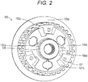
- the ring-shaped intermediate portion 105b is configured such that each of three support rod through-holes 108 is formed between adjacent ones of three center-side cam portions 107 arranged in a circumferential direction.
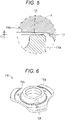
- Three center-side cam portions 107 are raised portions forming center-side assist cam surfaces 107a and center-side slipper cam surfaces 107b.
- Three center-side cam portions 107 are formed to extend along the circumferential direction of the center clutch 105.
- center-side cam portions 107 are equally formed along the circumferential direction of the center clutch 105. Moreover, each center-side cam portion 107 is formed such that an inner peripheral portion thereof is connected integrally with the shaft coupling portion 105a. Further, the center-side assist cam surface 107a and the center-side slipper cam surface 107b are each formed at both end portions of each center-side cam portion 107 in the circumferential direction of the center clutch 105.
- Each center-side assist cam surface 107a is a portion for generating, in cooperation with a later-described pressure-side assist cam surface 114a, assist torque as force for enhancing pressure contact force between the friction plate 103 and the clutch plate 104.
- Each center-side assist cam surface 107a is configured as an inclined surface gradually projecting to a pressure clutch 112 side along the circumferential direction of the center clutch 105. In this case, each center-side assist cam surface 107a is formed in a direction facing the support rod through-hole 108.
- Each center-side slipper cam surface 107b is a portion for generating, in cooperation with a later-described pressure-side slipper cam surface 114b, slipper torque as force for promptly separating the friction plate 103 and the clutch plate 104 to bring these plates into a half-clutch state.
- Each center-side slipper cam surface 107b is, on the side opposite to the center-side assist cam surface 107a in the circumferential direction, configured as an inclined surface inclined in the same direction as that of the center-side assist cam surface 107a.
- each center-side slipper cam surface 107b is formed in a direction facing the pressure clutch 112 side on the side opposite to the center-side assist cam surface 107a. Moreover, each center-side slipper cam surface 107b is formed to have the same length as the length of extension of the center-side assist cam surface 107a in the radial direction. That is, each center-side slipper cam surface 107b is formed to have the same area as the area of the center-side assist cam surface 107a at the same position in the radial direction as the formation position of the center-side assist cam surface 107a.
- each center-side slipper cam surface 107b may be formed to have an area different from the area of the center-side assist cam surface 107a at a position (a position shifted in the radial direction) different from the formation position of the center-side assist cam surface 107a in the radial direction.
- the above-described half-clutch state of the clutch device 100 means an incomplete transmission state, and in this state, part of the drive force of the engine is transmitted to a drive wheel side in a state before the friction plates 103 and the clutch plates 104 in the clutch device 100 are fully in close contact with each other.
- Three support rod through-holes 108 are through-holes for penetration of later-described three tubular support rods 115. These three support rod through-holes 108 are equally formed at positions among three center-side cam portions 107 along the circumferential direction of the center clutch 105.
- the plate holding portion 105c is a portion configured to hold part of the multiple clutch plates 104 together with the friction plates 103.
- the plate holding portion 105c is formed to have a cylindrical shape extending in the axial direction at an outer edge portion of the center clutch 105.
- the outer peripheral portion of the plate holding portion 105c includes an external-gear-shaped spline.
- the plate holding portion 105c holds the clutch plates 104 and the friction plates 103 in a state in which these plates are alternately arranged, are displaceable along the axis line direction of the center clutch 105, and are rotatable integrally with the center clutch 105.
- oil holes 105d as through-holes for guiding the clutch oil from the inside to the outside of the plate holding portion 105c in the radial direction are intermittently formed along the axial direction.
- a plate receiving portion 105e is formed at a tip end portion of the plate holding portion 105c.
- the plate receiving portion 105e is a portion configured to receive the clutch plates 104 and the friction plates 103 pressed by the pressure clutch 112 such that these plates are sandwiched between the plate receiving portion 105e and the pressure clutch 112.
- the plate receiving portion 105e is formed such that the tip end portion of the plate holding portion 105c formed in the cylindrical shape projects outwardly in the radial direction in a flange shape.
- a lifter plate slide portion 110 is formed at an inner peripheral surface of the plate holding portion 105c, which is formed in the cylindrical shape, in the radial direction.
- the lifter plate slide portion 110 is a portion on which a lifter plate 116 reciprocatably slides in the axial direction.
- the lifter plate slide portion 110 is formed by the inner peripheral surface of the plate holding portion 105c formed in the cylindrical shape.
- the lifter plate slide portion 110 is, at an end portion of the plate holding portion 105c on a plate receiving portion 105e side, formed to have a slightly longer length than the stroke of the lifter plate 116 in the axial direction.
- the shaft 111 is a shaft body formed in a hollow shape. Of the shaft 111, one end side (the right side as viewed in the figure) rotatably supports the input gear 102 and the clutch housing 101 through the bearing (not shown), and supports the spline-fitted center clutch 105 in a fixed manner through a nut (not shown). Of the shaft 111, the other end portion (the outer left side as viewed in the figure) is coupled to the transmission (not shown) of the two-wheel motor vehicle. That is, the shaft 111 is equivalent to a driven shaft of the present invention. Note that in Fig. 1 , the shaft 111 is indicated by a chain double-dashed line.
- the pressure clutch 112 is a component for pressing the friction plates 103 to cause the friction plates 103 and the clutch plates 104 to closely contact each other.
- the pressure clutch 112 is formed in such a manner that an aluminum alloy material is shaped into a substantially discoid shape having the substantially same outer diameter size as the outer diameter of the clutch plate 104. More specifically, the pressure clutch 112 is, as illustrated in Fig. 4 , mainly formed in such a manner that a ring-shaped intermediate portion 112a and the plate housing sub-portion 112b are integrally formed.
- the ring-shaped intermediate portion 112a is formed in a ring shape with a raised-recessed portion.
- the ring-shaped intermediate portion 112a is configured such that intermediate portions of three pressure-side cam portions 114 arranged on the circumference of such a ring body each have three tubular support rods 115.
- the ring-shaped intermediate portion 112a is slidably fitted onto the outer peripheral surface of the shaft coupling portion 105a of the center clutch 105. More specifically, the second center clutch slide portion 113 formed by an inner peripheral surface of a through-hole formed at a center portion is, at the ring-shaped intermediate portion 112a, slidably fitted onto the pressure clutch slide portion 106 formed at the outer peripheral surface of the shaft coupling portion 105a.
- the pressure clutch 112 is rotatably provided independently of the center clutch 105 and the shaft 111 at a position concentric with the clutch housing 101, the center clutch 105, and the shaft 111.
- the second center clutch slide portion 113 is a portion configured to allow tilting of the pressure clutch 112 with respect to the axial direction while guiding the pressure clutch 112 in the axial direction.
- the length of the second center clutch slide portion 113 in the axial direction is shorter than the length of a later-described first center clutch slide portion 120 in the axial direction.
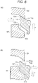
- a clearance C2 as a clearance between the second center clutch slide portion 113 and the pressure clutch slide portion 106 is, as illustrated in Fig. 5 , is set to such an amount that tilting of the pressure clutch 112 with respect to the axial direction when the pressure clutch 112 reciprocatably slides in the axial direction is allowed. In tilting of the pressure clutch 112 in this case, smooth reciprocatable slide of the pressure clutch 112 in the axial direction is ensured.
- cam surfaces of the pressure-side cam portions 114 and cam surfaces of the center-side cam portions 107 are brought into or come close to a parallel state, and therefore, are ideally brought into or come close to a surface contact state across the entire surface.
- the clearance C2 may be set to equal to or greater than three times and equal to or less than ten times as great as a later-described clearance C1, and may be more preferably set to equal to or greater than four times and equal to or less than seven times. In this case, the clearance C2 may be set within a range of 0.1 mm to 0.5 mm. In the present embodiment, the clearance C2 is set to 0.2 mm.
- Three pressure-side cam portions 114 are raised portions forming the pressure-side assist cam surfaces 114a and the pressure-side slipper cam surfaces 114b. Three pressure-side cam portions 114 are formed to extend along the circumferential direction of the pressure clutch 112. In this case, three pressure-side cam portions 114 are equally formed along the circumferential direction of the pressure clutch 112. Moreover, each pressure-side cam portion 114 is formed such that an outer peripheral portion thereof is connected integrally with the plate housing sub-portion 112b. Further, the pressure-side assist cam surface 114a and the pressure-side slipper cam surface 114b are each formed at both end portions of each pressure-side cam portion 114 in the circumferential direction of the pressure clutch 112.
- Each pressure-side assist cam surface 114a is a portion configured to slide on the center-side assist cam surface 107a of the center clutch 105.
- Each pressure-side assist cam surface 114a is configured as an inclined surface gradually projecting to a center clutch 105 side along the circumferential direction of the pressure clutch 112. That is, the center-side assist cam surfaces 107a and the pressure-side assist cam surfaces 114a form an assist mechanism.
- Each pressure-side slipper cam surface 114b is a portion configured to slide on the center-side slipper cam surface 107b.
- Each pressure-side slipper cam surface 114b is configured as an inclined surface extending in the same direction as that of the pressure-side assist cam surface 114a on the side opposite to the pressure-side assist cam surface 114a in the circumferential direction. That is, the center-side slipper cam surfaces 107b and the pressure-side slipper cam surfaces 114b form a slipper mechanism.
- Each pressure-side slipper cam surface 114b is formed to have the same length and area as the length and area of the pressure-side assist cam surface 114a in the radial direction. That is, each pressure-side slipper cam surface 114b is formed to have the same area as the area of the center-side slipper cam surface 107b at a position facing the center-side slipper cam surface 107b. Note that each pressure-side slipper cam surface 114b may be formed to have an area different from the area of the pressure-side assist cam surface 114a at a position (a position shifted in the radial direction) different from the formation position of the pressure-side assist cam surface 114a in the radial direction.
- Three tubular support rods 115 are cylindrical portions extending in a columnar shape in the axial direction of the center clutch 105 to support the lifter plate 116, and at inner peripheral portions thereof, are provided with internal threads. Three tubular support rods 115 are equally formed along the circumferential direction of the pressure clutch 112.
- the plate housing sub-portion 112b is a portion configured to hold the other part of the multiple clutch plates 104 together with the friction plates 103.
- the plate housing sub-portion 112b is, at an outer edge portion of the pressure clutch 112, formed to have a cylindrical shape extending in the axial direction.
- An outer peripheral portion of the plate housing sub-portion 112b includes an external-gear-shaped spline.
- the plate housing sub-portion 112b holds the clutch plates 104 and the friction plates 103 in a state in which these plates are alternately arranged, are displaceable along an axis line direction of the pressure clutch 112, and are rotatable integrally with the pressure clutch 112.
- the plate housing sub-portion 112b is formed to have a greater inner diameter than that of the plate holding portion 105c of the center clutch 105.
- the plate housing sub-portion 112b is configured fittable onto the plate holding portion 105c in a non-contact state.
- a plate pressing portion 112c is formed at a tip end portion of the plate housing sub-portion 112b.
- the plate pressing portion 112c is a portion for pressing the clutch plates 104 and the friction plates 103 held on the plate holding portion 105c toward the plate receiving portion 105e side such that the clutch plates 104 and the friction plates 103 closely contact each other with high pressure.
- the plate pressing portion 112c is formed such that a base portion of the plate housing sub-portion 112b formed in the cylindrical shape projects outwardly in the radial direction in a flange shape.
- the lifter plate 116 is a component for reciprocatably displacing the pressure clutch 112 in the axial direction, and is formed in such a manner that a metal material is formed into a cylindrical shape. More specifically, the lifter plate 116 mainly includes each of an operation receiving portion 116a and projecting portions 116b.
- the operation receiving portion 116a is a portion to be pressed by a clutch release mechanism through a release pin 117.
- the operation receiving portion 116a is formed to have a cylindrical shape housing the bearing pressed by the release pin 117.
- the clutch release mechanism is a mechanical device configured to press the release pin 117 to a shaft 111 side according to operation of a clutch operation lever (not shown) by a driver of a self-propelled vehicle on which the clutch device 100 is mounted.
- the release pin 117 is indicated by a chain double-dashed line.
- the projecting portion 116b is a portion configured such that a clutch spring 118 is sandwiched between the projecting portion 116b and the ring-shaped intermediate portion 105b of the center clutch 105 and configured to guide the lifter plate 116 in the axial direction.
- the projecting portion 116b is formed in a plate shape projecting outward of an outer peripheral portion of the operation receiving portion 116a in the radial direction. In this case, the projecting portions 116b are formed to project from three spots of the outer peripheral portion of the operation receiving portion 116a at equal intervals in the circumferential direction.
- projecting portions 116b are each attached to tip end portions of three tubular support rods 115 through attachment bolts in a state in which the ring-shaped intermediate portion 105b and the projecting portions 116b sandwich the clutch springs 118 on the opposite side of the center clutch 105 from the pressure clutch 112. That is, the lifter plate 116 displaces and rotates relative to the center clutch 105 integrally with the pressure clutch 112.
- the clutch spring 118 is an elastic body for pressing the pressure clutch 112 to the center clutch 105 side to press the plate pressing portion 112c of the pressure clutch 112 against the friction plates 103.
- the clutch spring 118 includes a coil spring formed in such a manner that spring steel is wound in a spiral shape.
- the clutch spring 118 is arranged between adjacent ones of three tubular support rods 115.
- the first center clutch slide portion 120 is formed at a tip end portion of each projecting portion 116b.
- the first center clutch slide portion 120 is a portion for guiding the lifter plate 116 in the axial direction.
- the first center clutch slide portions 120 are formed to have a circumferential surface at outer peripheral surfaces of three projecting portions 116b.
- each first center clutch slide portion 120 is formed to have a greater thickness than that of an inner portion for pressing the clutch spring 118.
- the length of the first center clutch slide portion 120 in the axial direction is longer than the length of the second center clutch slide portion 113 in the axial direction.
- the clearance C1 as a clearance between the first center clutch slide portion 120 and the lifter plate slide portion 110 is set to such an amount that when the lifter plate 116 reciprocatably slides in the axial direction, a change in the posture of the lifter plate 116 is suppressed while the lifter plate 116 is smoothly reciprocatably sliding.
- the clearance C1 is set within a range of 0.01 mm to 0.08 mm. In the present embodiment, the clearance C1 is set to 0.02 mm.
- the clutch device 100 is filled with a predetermined amount of clutch oil (not shown).
- the clutch oil is mainly supplied to among the friction plates 103 and the clutch plates 104 to absorb friction heat generated thereamong and prevent abrasion of the friction members. That is, the clutch device 100 is a so-called wet multiplate friction clutch device.
- the clutch device 100 is arranged between the engine and the transmission in the vehicle.
- the clutch device 100 performs, according to operation of the clutch operation lever by the driver of the vehicle, transmission of the drive force of the engine to the transmission and blocking of such transmission.
- the clutch release mechanism (not shown) does not press the release pin 117, and therefore, the pressure clutch 112 presses the friction plates 103 by elastic force of the clutch springs 118.
- the friction plates 103 and the clutch plates 104 are brought into a clutch ON state in which these plates are pressed against each other and are friction-coupled to each other, and the center clutch 105 is rotatably driven. That is, rotary drive force of the motor is transmitted to the center clutch 105, and in this manner, the shaft 111 is rotatably driven.
- the pressure clutch 112 displaces (a b-arrow in the figure) in the direction of approaching the center clutch 105 while rotating relative to the center clutch 105 by cam action (an a-arrow in the figure) in which the pressure-side assist cam surface 114a formed at the pressure clutch 112 moves over the center-side assist cam surface 107a formed at the center clutch 105.
- the pressure clutch 112 displaces (a d-arrow in the figure) in the direction of separating from the center clutch 105 while rotating relative to the center clutch 105 by cam action (a c-arrow in the figure) in which the pressure-side slipper cam surface 114b formed at the pressure clutch 112 moves over the center-side slipper cam surface 107b formed at the center clutch 105, as illustrated in Fig. 8(B) .
- the friction plates 103 and the clutch plates 104 start separating from each other. Accordingly, a state in which these plates are pressed against each other is weakened, and a state in which friction coupling is weakened is brought.
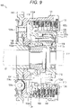
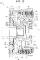
- the clutch release mechanism presses the release pin 117 as illustrated in Fig. 9 .
- the pressure clutch 112 displaces in the direction of separating from the center clutch 105 against the elastic force of the clutch springs 118.
- the first center clutch slide portions 120 of the lifter plate 116 slide on the lifter plate slide portion 110 of the center clutch 105 through the clearance C1, and therefore, the pressure clutch 112 is smoothly and stably guided along the axial direction of the center clutch 105.
- the center clutch 105 is brought into a clutch OFF state in which friction coupling among the friction plates 103 and the clutch plates 104 is cancelled.
- a state in which rotary drive is attenuated or stopped is brought. That is, the rotary drive force of the motor is blocked from the center clutch 105.
- the center-side assist cam surface 107a and the pressure-side assist cam surface 114a are in a separate state, and the center-side slipper cam surface 107b and the pressure-side slipper cam surface 114b are in a separate state.
- each of the assist torque and the slipper torque is not generated.
- the assist function acts.
- the pressure-side assist cam surface 114a tilts with respect to the center-side assist cam surface 107a when the pressure-side assist cam surface 114a contacts the center-side assist cam surface 107a
- the entirety of the pressure clutch 112 is, as in action of the assist function, inclined such that the pressure-side assist cam surface 114a is along the center-side assist cam surface 107a.
- center-side assist cam surface 107a and the pressure-side assist cam surface 114a are brought into or come close to the parallel state, and therefore, the cam surfaces thereof are brought into or come close to the surface contact state across the entire surface.
- efficient torque transmission is performed.
- the clearance C2 between the second center clutch slide portion 113 and the pressure clutch slide portion 106 sliding on each other in the vicinity of the center-side cam portions 107 and the pressure-side cam portions 114 is set to a greater value than the clearance C1 between each first center clutch slide portion 120 and the lifter plate slide portion 110 sliding on each other at a position apart from each of these cam portions.
- the first center clutch slide portions 120 slide on the lifter plate slide portion 110.
- the pressure clutch 112 can be guided on the same axis as that of the center clutch 105, a change in tilting of the pressure clutch 112 can be accepted by the clearance C2 between the second center clutch slide portion 113 and the pressure clutch slide portion 106, and the pressure-side cam portions 114 of the pressure clutch 112 can slide in close contact with the center-side cam portions 107 of the center clutch 105.
- the clutch device 100 can improve close contactability between the center-side cam portion 107 of the center clutch 105 and the pressure-side cam portion 114 of the pressure clutch 112, and can stabilize torque transmission.
- the clutch device 100 is configured such that the center-side cam portion 107 includes the center-side assist cam surface 107a and the center-side slipper cam surface 107b and the pressure-side cam portion 114 includes the pressure-side assist cam surface 114a and the pressure-side slipper cam surface 114b. That is, the center-side cam portion 107 and the pressure-side cam portion 114 are equivalent to a cam portion according to the present invention. However, each of the center-side cam portion 107 and the pressure-side cam portion 114 may include at least one of the assist-side cam surface and the slipper-side cam surface.
- the lifter plate slide portion 110 is formed at an inner surface of the plate holding portion 105c in the radial direction.
- the lifter plate 116 slides at a position facing the inside of the plate holding portion 105c in the radial direction.
- the lifter plate slide portion 110 may be formed at an inner surface of the plate receiving portion 105e in the radial direction, and may be configured such that the lifter plate 116 slides on such a portion.
- the plate receiving portion 105e may be formed to have a thickness (a length in the axial direction) of equal to or greater than the stroke of the lifter plate 116. According to such a configuration, the lifter plate 116 can stably slide by the thick plate receiving portion 105e.
- the first center clutch slide portion 120 is formed such that the length of the shaft 111 in the axial direction is longer than that of the second center clutch slide portion 113.
- the clutch device 100 can reciprocatably slide, with favorable accuracy, the pressure clutch 112 in the axial direction of the center clutch 105.
- the length of the shaft 111 in the axial direction at the first center clutch slide portion 120 may be shorter than that of the second center clutch slide portion 113 so that the acceptable amount of tilting of the pressure clutch 112 can be increased.
- the length of the shaft 111 in the axial direction may be, at the first center clutch slide portion 120, the same as the length of the second center clutch slide portion 113.
- the second center clutch slide portion 113 is formed at the position overlapping with the pressure-side cam portions 114 in the axial direction of the shaft 111, i.e., formed inside the pressure-side cam portions 114 in the radial direction.
- the amount of tilting of the pressure clutch 112 can be easily defined by the clearance C2 between the second center clutch slide portion 113 and the pressure clutch slide portion 106.
- the second center clutch slide portion 113 may be also formed at a position not overlapping with the pressure-side cam portions 114 on the side opposite to a first center clutch slide portion 120 side in the axial direction of the shaft 111. According to such a configuration, in the clutch device 100, a distance between the first center clutch slide portion 120 and the second center clutch slide portion 113 is further increased. Thus, the amount of tilting of the pressure clutch 112 can be more finely defined, and therefore, can be easily defined with high accuracy.
- the first center clutch slide portions 120 are each formed at three projecting portions 116b of the lifter plate 116. However, four or more projecting portions 116b may be provided, and the first center clutch slide portions 120 may be formed on the outer peripheral surfaces of these projecting portions 116b. Alternatively, the projecting portion 116b may be formed in a discoid shape connected as one, and the first center clutch slide portion 120 may be formed at an outer peripheral surface of such a discoid body.
- the second center clutch slide portion 113 is formed as the circumferential surface continuous to an inner peripheral surface of the ring-shaped intermediate portion 112a.
- one or more projecting portions projecting inwardly in the radial direction may be provided on the inner peripheral surface of the ring-shaped intermediate portion 112a, and the second center clutch slide portion 113 may be formed in an arc shape at inner peripheral surfaces of such projecting portions.
Landscapes
- Engineering & Computer Science (AREA)
- General Engineering & Computer Science (AREA)
- Mechanical Engineering (AREA)
- Mechanical Operated Clutches (AREA)
- One-Way And Automatic Clutches, And Combinations Of Different Clutches (AREA)
Applications Claiming Priority (2)
| Application Number | Priority Date | Filing Date | Title |
|---|---|---|---|
| JP2018048909A JP7231333B2 (ja) | 2018-03-16 | 2018-03-16 | クラッチ装置 |
| PCT/JP2019/007474 WO2019176537A1 (ja) | 2018-03-16 | 2019-02-27 | クラッチ装置 |
Publications (3)
| Publication Number | Publication Date |
|---|---|
| EP3767121A1 EP3767121A1 (en) | 2021-01-20 |
| EP3767121A4 EP3767121A4 (en) | 2021-12-08 |
| EP3767121B1 true EP3767121B1 (en) | 2023-01-11 |
Family
ID=67906665
Family Applications (1)
| Application Number | Title | Priority Date | Filing Date |
|---|---|---|---|
| EP19767173.8A Active EP3767121B1 (en) | 2018-03-16 | 2019-02-27 | Clutch device |
Country Status (6)
| Country | Link |
|---|---|
| US (1) | US11231074B2 (enExample) |
| EP (1) | EP3767121B1 (enExample) |
| JP (1) | JP7231333B2 (enExample) |
| CN (1) | CN111512059B (enExample) |
| TW (1) | TWI794410B (enExample) |
| WO (1) | WO2019176537A1 (enExample) |
Families Citing this family (12)
| Publication number | Priority date | Publication date | Assignee | Title |
|---|---|---|---|---|
| EP4137716A4 (en) * | 2020-04-13 | 2024-08-14 | Kabushiki Kaisha F.C.C. | POWER TRANSMISSION DEVICE |
| CN114198429A (zh) * | 2021-12-13 | 2022-03-18 | 潍坊华源汽车部件有限公司 | 一种带液冷装置的安全离合器 |
| JP7225461B1 (ja) * | 2022-06-30 | 2023-02-20 | 株式会社エフ・シー・シー | クラッチ装置および自動二輪車 |
| JP2024097326A (ja) * | 2022-07-05 | 2024-07-18 | 株式会社エフ・シー・シー | クラッチ装置 |
| EP4477906A4 (en) * | 2022-07-05 | 2025-06-25 | Kabushiki Kaisha F.C.C. | COUPLING DEVICE |
| JP7212193B1 (ja) * | 2022-07-06 | 2023-01-24 | 株式会社エフ・シー・シー | クラッチ装置および自動二輪車 |
| CN119213233A (zh) * | 2022-07-06 | 2024-12-27 | 株式会社F.C.C. | 离合器装置及摩托车 |
| JP7581288B2 (ja) * | 2022-07-21 | 2024-11-12 | 株式会社エフ・シー・シー | クラッチ装置 |
| JP7196356B1 (ja) * | 2022-09-06 | 2022-12-26 | 株式会社エフ・シー・シー | クラッチ装置および自動二輪車 |
| JP7626323B2 (ja) * | 2022-09-13 | 2025-02-04 | 株式会社エフ・シー・シー | クラッチ装置および自動二輪車 |
| CN117703950B (zh) * | 2022-09-13 | 2024-12-20 | 株式会社F.C.C. | 离合器装置及摩托车 |
| JP7252405B1 (ja) * | 2022-09-28 | 2023-04-04 | 株式会社エフ・シー・シー | クラッチ装置および自動二輪車 |
Family Cites Families (23)
| Publication number | Priority date | Publication date | Assignee | Title |
|---|---|---|---|---|
| JPS6458816A (en) * | 1987-08-28 | 1989-03-06 | Yamaha Motor Co Ltd | Friction clutch device for vehicle |
| JP3378097B2 (ja) | 1994-09-29 | 2003-02-17 | 本田技研工業株式会社 | 摩擦クラッチ |
| JP3631974B2 (ja) * | 2001-04-23 | 2005-03-23 | 株式会社エフ・シー・シー | クラッチ |
| US7014026B2 (en) * | 2001-06-07 | 2006-03-21 | Drussel Wilfley Design, L.L.C. | Manual/automatic pressure control mechanism for centrifugal clutch |
| JP2003329064A (ja) * | 2002-05-10 | 2003-11-19 | Yamaha Motor Co Ltd | クラッチ接続制御装置 |
| JP4744225B2 (ja) * | 2005-08-04 | 2011-08-10 | 本田技研工業株式会社 | クラッチレバー軸の配置構造 |
| JP4662896B2 (ja) | 2006-08-07 | 2011-03-30 | 本田技研工業株式会社 | 多板クラッチ |
| JP4805092B2 (ja) * | 2006-10-25 | 2011-11-02 | 本田技研工業株式会社 | 多板式クラッチ装置 |
| JP4922226B2 (ja) * | 2008-03-28 | 2012-04-25 | 本田技研工業株式会社 | 車両用クラッチ |
| JP5191819B2 (ja) * | 2008-06-27 | 2013-05-08 | 本田技研工業株式会社 | 多板クラッチ |
| JP4990253B2 (ja) * | 2008-09-30 | 2012-08-01 | 本田技研工業株式会社 | 多板式クラッチ |
| JP4907642B2 (ja) * | 2008-12-25 | 2012-04-04 | 本田技研工業株式会社 | 多板式クラッチ装置 |
| JP4939585B2 (ja) * | 2009-09-30 | 2012-05-30 | 本田技研工業株式会社 | 多板クラッチ装置 |
| JP5502507B2 (ja) * | 2010-01-27 | 2014-05-28 | 株式会社エフ・シー・シー | 動力伝達装置 |
| US9157488B2 (en) * | 2012-03-29 | 2015-10-13 | Honda Motor Co., Ltd. | Clutch apparatus |
| CN104350300B (zh) | 2012-06-04 | 2017-03-08 | 株式会社F.C.C. | 动力传递装置 |
| JP6265489B2 (ja) * | 2014-10-14 | 2018-01-24 | 株式会社エフ・シー・シー | クラッチ装置 |
| JP6801956B2 (ja) * | 2015-12-04 | 2020-12-16 | 株式会社エクセディ | モータサイクル用クラッチ装置 |
| JP6603143B2 (ja) | 2016-01-25 | 2019-11-06 | 株式会社エフ・シー・シー | 動力伝達装置 |
| JP6649824B2 (ja) * | 2016-03-23 | 2020-02-19 | 本田技研工業株式会社 | クラッチ装置 |
| JP6553696B2 (ja) * | 2017-10-26 | 2019-07-31 | 株式会社エフ・シー・シー | クラッチ装置 |
| JP6710709B2 (ja) * | 2018-01-10 | 2020-06-17 | 本田技研工業株式会社 | 多板式摩擦クラッチ |
| JP6851340B2 (ja) * | 2018-03-14 | 2021-03-31 | 株式会社エクセディ | クラッチ装置 |
-
2018
- 2018-03-16 JP JP2018048909A patent/JP7231333B2/ja active Active
-
2019
- 2019-02-14 TW TW108104928A patent/TWI794410B/zh active
- 2019-02-27 US US16/966,699 patent/US11231074B2/en active Active
- 2019-02-27 EP EP19767173.8A patent/EP3767121B1/en active Active
- 2019-02-27 WO PCT/JP2019/007474 patent/WO2019176537A1/ja not_active Ceased
- 2019-02-27 CN CN201980006722.9A patent/CN111512059B/zh active Active
Also Published As
| Publication number | Publication date |
|---|---|
| EP3767121A4 (en) | 2021-12-08 |
| BR112020015760A2 (pt) | 2020-12-08 |
| US20210033154A1 (en) | 2021-02-04 |
| US11231074B2 (en) | 2022-01-25 |
| JP7231333B2 (ja) | 2023-03-01 |
| JP2019158087A (ja) | 2019-09-19 |
| CN111512059A (zh) | 2020-08-07 |
| CN111512059B (zh) | 2022-07-05 |
| WO2019176537A1 (ja) | 2019-09-19 |
| EP3767121A1 (en) | 2021-01-20 |
| TW201938925A (zh) | 2019-10-01 |
| TWI794410B (zh) | 2023-03-01 |
Similar Documents
| Publication | Publication Date | Title |
|---|---|---|
| EP3767121B1 (en) | Clutch device | |
| US11215237B2 (en) | Clutch device | |
| US20110214522A1 (en) | Shifting clutch | |
| EP2530348B1 (en) | Power transmission device | |
| EP2781781B1 (en) | Clutch device | |
| EP2037142B1 (en) | Power transmitting apparatus | |
| EP3633220B1 (en) | Clutch device | |
| US11073184B2 (en) | Power transmission device | |
| KR102341102B1 (ko) | 마찰 링, 동기화 링, 동기화 유닛 및 차량용 가변비 기어 전동 장치 | |
| US11118635B2 (en) | Power transmission device | |
| US10267368B2 (en) | Spring pack assembly for a torque transmitting device | |
| WO2016114327A1 (ja) | カム装置およびステアリングホイールの位置調節装置 | |
| US8490768B2 (en) | Multi-plate clutch system | |
| US20220341474A1 (en) | Power Transmission Device | |
| JP2019086154A (ja) | クラッチ装置 | |
| EP3608556B1 (en) | Clutch friction plate and clutch device | |
| US9347499B2 (en) | Shift device with synchronizer | |
| EP4039999A1 (en) | Clutch device | |
| EP3591247A1 (en) | Synchronizer for a mechanical transmission, particularly for a transmission of a vehicle | |
| SE511438C2 (sv) | Synkroniseringsanordning i en fordonsväxellåda | |
| BR112020015760B1 (pt) | Dispositivo de embreagem | |
| JP2018179272A (ja) | 自動変速機におけるリテーニングプレートの支持構造 | |
| JP2013238255A (ja) | カム機構、駆動力伝達装置、およびモータカム装置 |
Legal Events
| Date | Code | Title | Description |
|---|---|---|---|
| STAA | Information on the status of an ep patent application or granted ep patent |
Free format text: STATUS: THE INTERNATIONAL PUBLICATION HAS BEEN MADE |
|
| PUAI | Public reference made under article 153(3) epc to a published international application that has entered the european phase |
Free format text: ORIGINAL CODE: 0009012 |
|
| STAA | Information on the status of an ep patent application or granted ep patent |
Free format text: STATUS: REQUEST FOR EXAMINATION WAS MADE |
|
| 17P | Request for examination filed |
Effective date: 20200902 |
|
| AK | Designated contracting states |
Kind code of ref document: A1 Designated state(s): AL AT BE BG CH CY CZ DE DK EE ES FI FR GB GR HR HU IE IS IT LI LT LU LV MC MK MT NL NO PL PT RO RS SE SI SK SM TR |
|
| AX | Request for extension of the european patent |
Extension state: BA ME |
|
| DAV | Request for validation of the european patent (deleted) | ||
| DAX | Request for extension of the european patent (deleted) | ||
| A4 | Supplementary search report drawn up and despatched |
Effective date: 20211105 |
|
| RIC1 | Information provided on ipc code assigned before grant |
Ipc: F16D 43/21 20060101ALI20211029BHEP Ipc: F16D 13/52 20060101AFI20211029BHEP |
|
| GRAP | Despatch of communication of intention to grant a patent |
Free format text: ORIGINAL CODE: EPIDOSNIGR1 |
|
| STAA | Information on the status of an ep patent application or granted ep patent |
Free format text: STATUS: GRANT OF PATENT IS INTENDED |
|
| INTG | Intention to grant announced |
Effective date: 20220719 |
|
| INTG | Intention to grant announced |
Effective date: 20220729 |
|
| GRAS | Grant fee paid |
Free format text: ORIGINAL CODE: EPIDOSNIGR3 |
|
| GRAA | (expected) grant |
Free format text: ORIGINAL CODE: 0009210 |
|
| STAA | Information on the status of an ep patent application or granted ep patent |
Free format text: STATUS: THE PATENT HAS BEEN GRANTED |
|
| AK | Designated contracting states |
Kind code of ref document: B1 Designated state(s): AL AT BE BG CH CY CZ DE DK EE ES FI FR GB GR HR HU IE IS IT LI LT LU LV MC MK MT NL NO PL PT RO RS SE SI SK SM TR |
|
| REG | Reference to a national code |
Ref country code: GB Ref legal event code: FG4D |
|
| REG | Reference to a national code |
Ref country code: CH Ref legal event code: EP |
|
| REG | Reference to a national code |
Ref country code: DE Ref legal event code: R096 Ref document number: 602019024328 Country of ref document: DE |
|
| REG | Reference to a national code |
Ref country code: IE Ref legal event code: FG4D |
|
| REG | Reference to a national code |
Ref country code: AT Ref legal event code: REF Ref document number: 1543601 Country of ref document: AT Kind code of ref document: T Effective date: 20230215 |
|
| REG | Reference to a national code |
Ref country code: LT Ref legal event code: MG9D |
|
| REG | Reference to a national code |
Ref country code: NL Ref legal event code: MP Effective date: 20230111 |
|
| PG25 | Lapsed in a contracting state [announced via postgrant information from national office to epo] |
Ref country code: NL Free format text: LAPSE BECAUSE OF FAILURE TO SUBMIT A TRANSLATION OF THE DESCRIPTION OR TO PAY THE FEE WITHIN THE PRESCRIBED TIME-LIMIT Effective date: 20230111 |
|
| PG25 | Lapsed in a contracting state [announced via postgrant information from national office to epo] |
Ref country code: RS Free format text: LAPSE BECAUSE OF FAILURE TO SUBMIT A TRANSLATION OF THE DESCRIPTION OR TO PAY THE FEE WITHIN THE PRESCRIBED TIME-LIMIT Effective date: 20230111 Ref country code: PT Free format text: LAPSE BECAUSE OF FAILURE TO SUBMIT A TRANSLATION OF THE DESCRIPTION OR TO PAY THE FEE WITHIN THE PRESCRIBED TIME-LIMIT Effective date: 20230511 Ref country code: NO Free format text: LAPSE BECAUSE OF FAILURE TO SUBMIT A TRANSLATION OF THE DESCRIPTION OR TO PAY THE FEE WITHIN THE PRESCRIBED TIME-LIMIT Effective date: 20230411 Ref country code: LV Free format text: LAPSE BECAUSE OF FAILURE TO SUBMIT A TRANSLATION OF THE DESCRIPTION OR TO PAY THE FEE WITHIN THE PRESCRIBED TIME-LIMIT Effective date: 20230111 Ref country code: LT Free format text: LAPSE BECAUSE OF FAILURE TO SUBMIT A TRANSLATION OF THE DESCRIPTION OR TO PAY THE FEE WITHIN THE PRESCRIBED TIME-LIMIT Effective date: 20230111 Ref country code: HR Free format text: LAPSE BECAUSE OF FAILURE TO SUBMIT A TRANSLATION OF THE DESCRIPTION OR TO PAY THE FEE WITHIN THE PRESCRIBED TIME-LIMIT Effective date: 20230111 Ref country code: ES Free format text: LAPSE BECAUSE OF FAILURE TO SUBMIT A TRANSLATION OF THE DESCRIPTION OR TO PAY THE FEE WITHIN THE PRESCRIBED TIME-LIMIT Effective date: 20230111 |
|
| PG25 | Lapsed in a contracting state [announced via postgrant information from national office to epo] |
Ref country code: SE Free format text: LAPSE BECAUSE OF FAILURE TO SUBMIT A TRANSLATION OF THE DESCRIPTION OR TO PAY THE FEE WITHIN THE PRESCRIBED TIME-LIMIT Effective date: 20230111 Ref country code: PL Free format text: LAPSE BECAUSE OF FAILURE TO SUBMIT A TRANSLATION OF THE DESCRIPTION OR TO PAY THE FEE WITHIN THE PRESCRIBED TIME-LIMIT Effective date: 20230111 Ref country code: IS Free format text: LAPSE BECAUSE OF FAILURE TO SUBMIT A TRANSLATION OF THE DESCRIPTION OR TO PAY THE FEE WITHIN THE PRESCRIBED TIME-LIMIT Effective date: 20230511 Ref country code: GR Free format text: LAPSE BECAUSE OF FAILURE TO SUBMIT A TRANSLATION OF THE DESCRIPTION OR TO PAY THE FEE WITHIN THE PRESCRIBED TIME-LIMIT Effective date: 20230412 Ref country code: FI Free format text: LAPSE BECAUSE OF FAILURE TO SUBMIT A TRANSLATION OF THE DESCRIPTION OR TO PAY THE FEE WITHIN THE PRESCRIBED TIME-LIMIT Effective date: 20230111 |
|
| REG | Reference to a national code |
Ref country code: CH Ref legal event code: PL |
|
| REG | Reference to a national code |
Ref country code: DE Ref legal event code: R097 Ref document number: 602019024328 Country of ref document: DE |
|
| REG | Reference to a national code |
Ref country code: BE Ref legal event code: MM Effective date: 20230228 |
|
| PG25 | Lapsed in a contracting state [announced via postgrant information from national office to epo] |
Ref country code: SM Free format text: LAPSE BECAUSE OF FAILURE TO SUBMIT A TRANSLATION OF THE DESCRIPTION OR TO PAY THE FEE WITHIN THE PRESCRIBED TIME-LIMIT Effective date: 20230111 Ref country code: RO Free format text: LAPSE BECAUSE OF FAILURE TO SUBMIT A TRANSLATION OF THE DESCRIPTION OR TO PAY THE FEE WITHIN THE PRESCRIBED TIME-LIMIT Effective date: 20230111 Ref country code: MC Free format text: LAPSE BECAUSE OF FAILURE TO SUBMIT A TRANSLATION OF THE DESCRIPTION OR TO PAY THE FEE WITHIN THE PRESCRIBED TIME-LIMIT Effective date: 20230111 Ref country code: LU Free format text: LAPSE BECAUSE OF NON-PAYMENT OF DUE FEES Effective date: 20230227 Ref country code: LI Free format text: LAPSE BECAUSE OF NON-PAYMENT OF DUE FEES Effective date: 20230228 Ref country code: EE Free format text: LAPSE BECAUSE OF FAILURE TO SUBMIT A TRANSLATION OF THE DESCRIPTION OR TO PAY THE FEE WITHIN THE PRESCRIBED TIME-LIMIT Effective date: 20230111 Ref country code: DK Free format text: LAPSE BECAUSE OF FAILURE TO SUBMIT A TRANSLATION OF THE DESCRIPTION OR TO PAY THE FEE WITHIN THE PRESCRIBED TIME-LIMIT Effective date: 20230111 Ref country code: CZ Free format text: LAPSE BECAUSE OF FAILURE TO SUBMIT A TRANSLATION OF THE DESCRIPTION OR TO PAY THE FEE WITHIN THE PRESCRIBED TIME-LIMIT Effective date: 20230111 Ref country code: CH Free format text: LAPSE BECAUSE OF NON-PAYMENT OF DUE FEES Effective date: 20230228 |
|
| REG | Reference to a national code |
Ref country code: AT Ref legal event code: UEP Ref document number: 1543601 Country of ref document: AT Kind code of ref document: T Effective date: 20230111 |
|
| PLBE | No opposition filed within time limit |
Free format text: ORIGINAL CODE: 0009261 |
|
| STAA | Information on the status of an ep patent application or granted ep patent |
Free format text: STATUS: NO OPPOSITION FILED WITHIN TIME LIMIT |
|
| PG25 | Lapsed in a contracting state [announced via postgrant information from national office to epo] |
Ref country code: SK Free format text: LAPSE BECAUSE OF FAILURE TO SUBMIT A TRANSLATION OF THE DESCRIPTION OR TO PAY THE FEE WITHIN THE PRESCRIBED TIME-LIMIT Effective date: 20230111 |
|
| 26N | No opposition filed |
Effective date: 20231012 |
|
| REG | Reference to a national code |
Ref country code: IE Ref legal event code: MM4A |
|
| PG25 | Lapsed in a contracting state [announced via postgrant information from national office to epo] |
Ref country code: SI Free format text: LAPSE BECAUSE OF FAILURE TO SUBMIT A TRANSLATION OF THE DESCRIPTION OR TO PAY THE FEE WITHIN THE PRESCRIBED TIME-LIMIT Effective date: 20230111 Ref country code: IE Free format text: LAPSE BECAUSE OF NON-PAYMENT OF DUE FEES Effective date: 20230227 Ref country code: FR Free format text: LAPSE BECAUSE OF NON-PAYMENT OF DUE FEES Effective date: 20230311 |
|
| PG25 | Lapsed in a contracting state [announced via postgrant information from national office to epo] |
Ref country code: BE Free format text: LAPSE BECAUSE OF NON-PAYMENT OF DUE FEES Effective date: 20230228 |
|
| PG25 | Lapsed in a contracting state [announced via postgrant information from national office to epo] |
Ref country code: BG Free format text: LAPSE BECAUSE OF FAILURE TO SUBMIT A TRANSLATION OF THE DESCRIPTION OR TO PAY THE FEE WITHIN THE PRESCRIBED TIME-LIMIT Effective date: 20230111 |
|
| PG25 | Lapsed in a contracting state [announced via postgrant information from national office to epo] |
Ref country code: BG Free format text: LAPSE BECAUSE OF FAILURE TO SUBMIT A TRANSLATION OF THE DESCRIPTION OR TO PAY THE FEE WITHIN THE PRESCRIBED TIME-LIMIT Effective date: 20230111 |
|
| PGFP | Annual fee paid to national office [announced via postgrant information from national office to epo] |
Ref country code: DE Payment date: 20241231 Year of fee payment: 7 |
|
| PGFP | Annual fee paid to national office [announced via postgrant information from national office to epo] |
Ref country code: AT Payment date: 20250127 Year of fee payment: 7 |
|
| PGFP | Annual fee paid to national office [announced via postgrant information from national office to epo] |
Ref country code: IT Payment date: 20250110 Year of fee payment: 7 Ref country code: GB Payment date: 20250102 Year of fee payment: 7 |
|
| PG25 | Lapsed in a contracting state [announced via postgrant information from national office to epo] |
Ref country code: CY Free format text: LAPSE BECAUSE OF FAILURE TO SUBMIT A TRANSLATION OF THE DESCRIPTION OR TO PAY THE FEE WITHIN THE PRESCRIBED TIME-LIMIT; INVALID AB INITIO Effective date: 20190227 |
|
| PG25 | Lapsed in a contracting state [announced via postgrant information from national office to epo] |
Ref country code: HU Free format text: LAPSE BECAUSE OF FAILURE TO SUBMIT A TRANSLATION OF THE DESCRIPTION OR TO PAY THE FEE WITHIN THE PRESCRIBED TIME-LIMIT; INVALID AB INITIO Effective date: 20190227 |