EP3758167A1 - Kupferdrahtlackabisoliergerät - Google Patents
Kupferdrahtlackabisoliergerät Download PDFInfo
- Publication number
- EP3758167A1 EP3758167A1 EP19841699.2A EP19841699A EP3758167A1 EP 3758167 A1 EP3758167 A1 EP 3758167A1 EP 19841699 A EP19841699 A EP 19841699A EP 3758167 A1 EP3758167 A1 EP 3758167A1
- Authority
- EP
- European Patent Office
- Prior art keywords
- copper wire
- blade holder
- plate
- stripping apparatus
- varnish
- Prior art date
- Legal status (The legal status is an assumption and is not a legal conclusion. Google has not performed a legal analysis and makes no representation as to the accuracy of the status listed.)
- Granted
Links
Images





Classifications
-
- H—ELECTRICITY
- H01—ELECTRIC ELEMENTS
- H01R—ELECTRICALLY-CONDUCTIVE CONNECTIONS; STRUCTURAL ASSOCIATIONS OF A PLURALITY OF MUTUALLY-INSULATED ELECTRICAL CONNECTING ELEMENTS; COUPLING DEVICES; CURRENT COLLECTORS
- H01R43/00—Apparatus or processes specially adapted for manufacturing, assembling, maintaining, or repairing of line connectors or current collectors or for joining electric conductors
- H01R43/28—Apparatus or processes specially adapted for manufacturing, assembling, maintaining, or repairing of line connectors or current collectors or for joining electric conductors for wire processing before connecting to contact members, not provided for in groups H01R43/02 - H01R43/26
-
- H—ELECTRICITY
- H02—GENERATION; CONVERSION OR DISTRIBUTION OF ELECTRIC POWER
- H02G—INSTALLATION OF ELECTRIC CABLES OR LINES, OR OF COMBINED OPTICAL AND ELECTRIC CABLES OR LINES
- H02G1/00—Methods or apparatus specially adapted for installing, maintaining, repairing or dismantling electric cables or lines
- H02G1/12—Methods or apparatus specially adapted for installing, maintaining, repairing or dismantling electric cables or lines for removing insulation or armouring from cables, e.g. from the end thereof
- H02G1/1285—Methods or apparatus specially adapted for installing, maintaining, repairing or dismantling electric cables or lines for removing insulation or armouring from cables, e.g. from the end thereof by friction, e.g. abrading, grinding, brushing
-
- H—ELECTRICITY
- H02—GENERATION; CONVERSION OR DISTRIBUTION OF ELECTRIC POWER
- H02K—DYNAMO-ELECTRIC MACHINES
- H02K15/00—Processes or apparatus specially adapted for manufacturing, assembling, maintaining or repairing of dynamo-electric machines
- H02K15/12—Impregnating, moulding insulation, heating or drying of windings, stators, rotors or machines
-
- H—ELECTRICITY
- H02—GENERATION; CONVERSION OR DISTRIBUTION OF ELECTRIC POWER
- H02G—INSTALLATION OF ELECTRIC CABLES OR LINES, OR OF COMBINED OPTICAL AND ELECTRIC CABLES OR LINES
- H02G1/00—Methods or apparatus specially adapted for installing, maintaining, repairing or dismantling electric cables or lines
- H02G1/12—Methods or apparatus specially adapted for installing, maintaining, repairing or dismantling electric cables or lines for removing insulation or armouring from cables, e.g. from the end thereof
- H02G1/1202—Methods or apparatus specially adapted for installing, maintaining, repairing or dismantling electric cables or lines for removing insulation or armouring from cables, e.g. from the end thereof by cutting and withdrawing insulation
- H02G1/1248—Machines
- H02G1/1251—Machines the cutting element not rotating about the wire or cable
- H02G1/1253—Machines the cutting element not rotating about the wire or cable making a transverse cut
- H02G1/1256—Machines the cutting element not rotating about the wire or cable making a transverse cut using wire or cable-clamping means
-
- H—ELECTRICITY
- H02—GENERATION; CONVERSION OR DISTRIBUTION OF ELECTRIC POWER
- H02K—DYNAMO-ELECTRIC MACHINES
- H02K15/00—Processes or apparatus specially adapted for manufacturing, assembling, maintaining or repairing of dynamo-electric machines
- H02K15/04—Processes or apparatus specially adapted for manufacturing, assembling, maintaining or repairing of dynamo-electric machines of windings prior to their mounting into the machines
- H02K15/0414—Processes or apparatus specially adapted for manufacturing, assembling, maintaining or repairing of dynamo-electric machines of windings prior to their mounting into the machines the windings consisting of separate elements, e.g. bars, segments or half coils
- H02K15/0421—Processes or apparatus specially adapted for manufacturing, assembling, maintaining or repairing of dynamo-electric machines of windings prior to their mounting into the machines the windings consisting of separate elements, e.g. bars, segments or half coils and consisting of single conductors, e.g. hairpins
-
- Y—GENERAL TAGGING OF NEW TECHNOLOGICAL DEVELOPMENTS; GENERAL TAGGING OF CROSS-SECTIONAL TECHNOLOGIES SPANNING OVER SEVERAL SECTIONS OF THE IPC; TECHNICAL SUBJECTS COVERED BY FORMER USPC CROSS-REFERENCE ART COLLECTIONS [XRACs] AND DIGESTS
- Y02—TECHNOLOGIES OR APPLICATIONS FOR MITIGATION OR ADAPTATION AGAINST CLIMATE CHANGE
- Y02W—CLIMATE CHANGE MITIGATION TECHNOLOGIES RELATED TO WASTEWATER TREATMENT OR WASTE MANAGEMENT
- Y02W30/00—Technologies for solid waste management
- Y02W30/50—Reuse, recycling or recovery technologies
- Y02W30/82—Recycling of waste of electrical or electronic equipment [WEEE]
Definitions
- This disclosure generally relates to the technical field of copper wire forming, and more particularly, to a copper wire varnish stripping apparatus.
- the copper wire After being unwound from a reel, the copper wire is cut, extruded and then formed into a certain shape. Between the unwinding and cutting steps, to improve the electrical conductivity of the copper wire, the varnish coating on the two ends of the copper wire needs to be scraped off.
- conventional stripping apparatuses perform a varnish scraping operation only after the cutting and extrusion forming are completed. The inconvenient removal of the varnish coating and the difficult clamping and fixing of the copper wire result in complicated operation and poor overall effect.
- the present disclosure provides a novel copper wire varnish stripping apparatus.
- the purpose of the present disclosure is to provide a copper wire varnish stripping apparatus, which may directly perform a varnish scraping operation on copper wire that is being conveyed, thus saving time and providing a good scraping effect.
- the present varnish stripping apparatus further collects the varnish coating such that the apparatus is tidy and has good safety.
- the present disclosure adopts the following technical solution: the copper wire varnish stripping apparatus comprising a bottom plate II, wherein a bottom surface of the bottom plate II is provided thereon with a linear motor, a top surface of the bottom plate II is provided thereon with a scraper mechanism, and two sides of the scraper mechanism are respectively provided with a pressing mechanism.
- the bottom plate II may be mounted on an assembly line such that the linear motor carries along the bottom plate II to move linearly.
- the two ends of a section of the copper wire are tightly pressed by the pressing mechanisms, and the copper wire has been conveyed over is scraped by the scraper mechanism arranged between the pressing mechanisms.
- the scraper mechanism of the present disclosure comprises a side plate arranged on the top surface of the bottom plate II, wherein a screw rod is rotatably connected to the side plate, and one end of the screw rod is sleeved with a synchronous belt II.
- a motor I is arranged on the synchronous belt II, a lead screw nut is arranged on the screw rod, and a moving platform is arranged on the lead screw nut.
- the moving platform is provided with a partition plate having a through hole, one side of the partition plate is provided with a vertical track, and the vertical track is slidably connected with an upper blade holder and a lower blade holder.
- the upper blade holder and the lower blade holder are respectively provided with a blade I.
- Lead screw nuts II are respectively arranged on the upper blade holder and the lower blade holder, a two-way screw rod I is arranged on the lead screw nuts II, and a motor II fixedly connected to the partition plate is arranged on the two-way screw rod I.
- the motor I propels the screw rod to rotate through the transmission of the synchronous belt II such that the lead screw nut on the screw rod carries along the moving platform to reciprocate.
- the partition plate is vertically mounted on the moving platform, and a vertical track is mounted on the moving platform.
- the motor II propels the two-way screw rod to rotate, thus making the upper blade holder and the lower blade holder move in the same direction or opposite directions, which enables the blades I to scrape the varnish coating off the upper and lower surfaces of the copper wire.
- the other side of the partition plate is provided with a horizontal track perpendicular to the vertical track, and the horizontal track is slidably connected to a left blade holder and a right blade holder.
- the left blade holder and the right blade holder are respectively provided with a blade II.
- Lead screw nuts III are respectively arranged on the left blade holder and the right blade holder, a two-way screw rod II is arranged on the lead screw nuts III, and a motor III fixedly connected to the partition plate is arranged on the two-way screw rod II.
- the motor III propels the two-way screw rod II to rotate, thus making the left blade holder and the right blade holder move in the same direction or opposite directions, which enables the blades II to scrape the varnish coating off the left and right surfaces of the copper wire.
- the pressing mechanism of the present disclosure comprises a side supporting plate arranged on the top surface of the bottom plate II, wherein an air cylinder III is arranged on the side supporting plate, and a pressing block is arranged at the telescopic end of the air cylinder III.
- a copper wire conveying plate is arranged below the pressing block, a guiding wheel group is arranged on the copper wire conveying plate, and the guiding wheel group comprises left and right guiding wheels II.
- the guiding wheels II are rotatably connected to the copper wire conveying plate.
- One end of the copper wire conveying plate is provided with an upper pressing wheel, and the upper pressing wheel is arranged above the copper wire conveying plate.
- the pressing block tightly presses the copper wire that has been conveyed over, and the guiding wheels II exerts an auxiliary conveying and guiding functions.
- the upper pressing wheel presses the upper surface of the copper wire that has been conveyed over, allows the copper wire to be stably conveyed and prevents the copper wire from warping upwards.
- the other end of the copper wire conveying plate is provided with a secondary varnish scraping block, and the secondary varnish scraping block is provided with a square hole located between each group of guiding wheels II.
- the square hole is used for allowing the copper wire that has been conveyed over to pass through, and the shape and size of the square hole matches the copper wire.
- the secondary varnish scraping block is arranged between the guiding wheels II, which makes the copper wire stay in a straight line during the conveying process, so that the conveying of the copper wire is facilitated.
- the square hole is covered by a scrap suction hood, and the scrap suction hood is provided with an air suction port.
- the varnish coating scraped off by the square hole is conveniently collected.
- the air suction port on the scrap suction hood allows an air suction apparatus to be easily installed.
- the air suction apparatus provides a negative pressure in the scrape suction hood, which effectively sucks away the scraps collected in the scrap suction hood, so that the accumulation and blocking are avoided.
- a guiding hole is formed in the copper wire conveying plate, and a guide post integrated with the pressing block is slidably connected within the guiding hole.
- the guiding hole is vertically formed in the copper wire conveying plate, and the guiding post is inserted in the corresponding guiding hole. In this way, when the pressing block moves up and down, the offset of the pressing block is avoided.
- the upper blade holder, the lower blade holder, the left blade holder and the right blade holder are respectively provided with an air path.
- Each air path is provided with an air inlet and an air outlet.
- the blades II and the blades II are respectively provided with a through hole II, and the through hole II is communicated with the air outlet.
- the upper blade holder, the lower blade holder, the left blade holder and the right blade holder are respectively covered by a connecting hood.
- the connecting hood is provided with a connecting pipe communicated with the interior of the connecting hood.
- a copper wire penetrating hole is formed in the pipe wall of the connecting pipe.
- the blades II and the blades II are respectively provided with a through hole II, and the through hole II is communicated with the air outlet.
- the air inlet allows air to enter.
- the air entering from the air inlet is blown out from the through hole II of the blade, thereby blown off the residual varnish coating left on the blades.
- the residual varnish coating falls into the connecting hood and is blown out from the connecting pipe such that the collection of the residual coating is completed. In this way, the scraps are prevented from being accumulated on the apparatus to affect the operation, and hidden dangers are avoided.
- the connecting hood is provided with an observing window, and the observing window is provided with a light-transmitting plate.
- the observing window and the light-transmitting plate allow a user to directly observe the collecting condition of the scraps.
- a process hole is formed in the air path, and a blocking screw is arranged in the process hole.
- the present disclosure has the following advantages: Due to the bottom plate II provided with a moving platform capable of reciprocating and the moving platform provided with an upper blade holder, a lower blade holder, a left blade holder and a right blade holder, the scraping operation may be performed on the four sides of the copper wire.
- the motors propel the two-way screw rods to rotate, thereby enabling the upper blade holder and the lower blade holder to move in the same direction or opposite directions, and enabling the left blade holder and the right blade holder to move in the same direction or opposite directions.
- the scraping depth of the blades may be accurately controlled, and a scraping operation may be divided into two scraping processes, which makes the scraping effect better and allows the scraping amount to be precisely controlled.
- the air outlet is communicated with the through hole II on the blade.
- the air outlet is provided with a connecting hood, when air enters from the air inlet, the varnish coating scraps may be blown off and then collected in the connecting hood and the connecting pipe, thereby achieving the collection of the scraps.
- the collecting condition of the scraps may be directly observed.
- the process hole facilitates the processing of the air path, the guiding wheels II allow the copper wire that is being conveyed to be guided and conveyed, and the upper pressing wheel prevents the copper wire from warping upwards.
- the varnish scraping block provided with the square hole, the secondary cleaning of the residual varnish coating on the copper wire is achieved, and through the scrap suction hood, the collection of the fallen varnish coating scraps is realized.
- the present disclosure has complete overall functions and strong practicability.
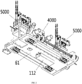
- the copper wire varnish stripping apparatus of the present disclosure comprises a bottom plate II 61, wherein a bottom surface of the bottom plate II is provided thereon with a linear motor 112, a top surface of the bottom plate II is provided thereon with a scraper mechanism 4000, and two sides of the scraper mechanism are respectively provided with a pressing mechanism 5000.
- the bottom plate II 61 may be mounted on an assembly line such that the linear motor carries along the bottom plate II to move linearly.
- the pressing mechanism 5000 is used for pressing and fixing the copper wire that has been conveyed over, pressing the two ends of a section of the copper wire that is being conveyed, and moving forward along with the copper wire.
- the scraper mechanism 4000 arranged between the two pressing mechanisms 5000 is used for performing a varnish scraping operation on the copper wire whose two ends are tightly pressed, thereby partially scraping the varnish coating off the surface of the copper wire that is being conveyed.
- the scraper mechanism 4000 of the present disclosure comprises a side plate 62 arranged on the top surface of the bottom plate II 61, wherein a screw rod 63 is rotatably connected to the side plate 62, and one end of the screw rod 63 is sleeved with a synchronous belt II 64.
- a motor I 65 is arranged on the synchronous belt II 64, a lead screw nut 66 is arranged on the screw rod 63, and a moving platform 67 is arranged on the lead screw nut 66.
- the moving platform 67 is provided with a partition plate 68 having a through hole, one side of the partition plate 68 is provided with a vertical track 69, and the vertical track 69 is slidably connected with an upper blade holder 70 and a lower blade holder 71.
- the upper blade holder 70 and the lower blade holder 71 are respectively provided with a blade I 72.
- Lead screw nuts II 73 are respectively arranged on the upper blade holder 70 and the lower blade holder 71, a two-way screw rod I 74 is arranged on the lead screw nuts II 73, and a motor II 75 fixedly connected to the partition plate 68 is arranged on the two-way screw rod I 74.
- the other side of the partition plate 68 is provided with a horizontal track (not shown) perpendicular to the vertical track 69, and the horizontal track is slidably connected to a left blade holder 77 and a right blade holder 78.
- the left blade holder 77 and the right blade holder 78 are respectively provided with a blade II 79.
- Lead screw nuts III 80 are respectively arranged on the left blade holder 77 and the right blade holder 78, a two-way screw rod II 81 is arranged on the lead screw nuts III 80, and a motor III 82 fixedly connected to the partition plate 68 is arranged on the two-way screw rod II 81.
- the forward and reverse rotation of the motor 65, as well as the transmission of the synchronous belt 64, enables the screw rod 63 to rotate, thus enabling the moving platform 67 fixedly mounted on the lead screw nut 66 to reciprocate on the screw rod 63.
- the motor II 75 controls the two-way screw rod I 74 to rotate.
- the two-way screw rod I 74 rotates clockwise, the upper blade holder 70 and the lower blade holder 71 move in opposite directions through the lead screw nuts II 73. In this way, the upper and lower positions of the copper wire passing through the through hole is fixed.
- the upper and lower end surfaces of the copper wire are clamped by the blades I 72 on the upper blade holder 70 and the lower blade holder 71, and the motor III 82 controls the two-way screw rod II 81 to rotate.
- the motor III 82 controls the two-way screw rod II 81 to rotate.
- the left blade holder 77 and the right blade holder 78 move in opposite directions through the lead screw nuts III 80 such that the left and right positions of the copper wire passing through the through hole is fixed.
- the left and right end surfaces of the copper wire is clamped by the blades II on the left blade holder 77 and the right blade holder 78.
- the blades I 72 and the blades II 79 clamping the copper wire interact to scrape the varnish coating off the upper, lower, left and right surfaces of the copper wire, thus partially completing the varnish scraping process.
- the motor II 75 and the motor III 82 re-control the two-way screw rod I 74 to rotate reversely, which allows the blades I 72 and the blades II 79 to release the copper wire.
- the copper wire varnish stripping apparatus of the present disclosure starts performing a varnish scraping operation from another position.
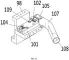
- the pressing mechanism 5000 of the present disclosure comprises a side supporting plate 98 arranged on the top surface of the bottom plate II 61, wherein an air cylinder III 99 is arranged on the side supporting plate 98, and a pressing block 100 is arranged at the telescopic end of the air cylinder III 99.
- a copper wire conveying plate 101 is arranged below the pressing block 100, a guiding wheel group is arranged on the copper wire conveying plate 101, and the guiding wheel group comprises left and right guiding wheels II 102.
- the guiding wheels II 102 are rotatably connected to the copper wire conveying plate 101.
- One end of the copper wire conveying plate 101 is provided with an upper pressing wheel 104, and the upper pressing wheel 104 is arranged above the copper wire conveying plate 101.
- the other end of the copper wire conveying plate 101 is provided with a secondary varnish scraping block 105, and the secondary varnish scraping block 105 is provided with a square hole 106 located between each group of guiding wheels II 102.
- the square hole 106 is used for allowing the copper wire that has been conveyed over to pass through, and the shape and size of the square hole 106 matches the copper wire.
- the copper wire that has been conveyed over passes through the square hole 106 first, then passes between the groups of guiding wheels II 102, and then goes out from the lower portion of the upper pressing wheel 104 on the other end of the copper wire conveying plate 101.
- the air cylinder III 99 is used for controlling the pressing block 100 to move up and down while tightly pressing the copper wire on the copper wire conveying plate 101.
- the square hole 106 is covered by a scrap suction hood 107, the scrap suction hood 107 is provided with an air suction port 108, and an air suction apparatus such as an air suction fan is installed in the air suction port 108.
- the air suction fan produces a negative pressure within the scrap suction hood 107, which allows the varnish coating scraps to be sucked and collected.
- a guiding hole 109 is formed in the copper wire conveying plate 101, and a guide post 110 integrated with the pressing block 100 is slidably connected within the guiding hole 109.
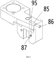
- the upper blade holder 70, the lower blade holder 71, the left blade holder 77 and the right blade holder 78 are respectively provided with an air path 85.
- Each air path 85 is provided with an air inlet 86 and an air outlet 87.
- the blades II 72 and the blades II 79 are respectively provided with a through hole II 88, and the through hole II 88 is communicated with the air outlet 87.
- the upper blade holder 70, the lower blade holder 71, the left blade holder 77 and the right blade holder 78 are respectively covered by a connecting hood 89.
- the connecting hood 89 is provided with a connecting pipe 90 communicated with the interior of the connecting hood 89.
- a copper wire penetrating hole 91 is formed in the pipe wall of the connecting pipe 90, and the copper wire penetrating hole 91 is used for allowing the copper wire that is being conveyed to pass through.
- the scraps varnish coating scraps
- the air path 85 the air may enter through the air inlet 86 to produce a positive pressure, which allows the scraps accumulated at the front end of the blades to be blown off into the connecting hood 89 and the connecting pipe 90.
- the connecting hood 89 is provided with an observing window 92, and the observing window 92 is provided with a light-transmitting plate 93 for allowing a user to directly observe the collecting condition of the scraps.
- a process hole 95 is formed in the air path 85, and a blocking screw 96 is arranged in the process hole 95.
- the scraping operation may be performed on the four sides of the copper wire.
- the motors propel the two-way screw rods to rotate, thereby enabling the upper blade holder and the lower blade holder to move in the same direction or opposite directions, and enabling the left blade holder and the right blade holder to move in the same direction or opposite directions.
- the scraping depth of the blades may be accurately controlled, and a scraping operation may be divided into two scraping processes, which makes the scraping effect better and allows the scraping amount to be precisely controlled.
- the air outlet is communicated with the through hole II on the blade.
- the air outlet is provided with a connecting hood, when air enters from the air inlet, the varnish coating scraps may be blown off and then collected in the connecting hood and the connecting pipe, thereby achieving the collection of the scraps.
- the collecting condition of the scraps may be directly observed.
- the process hole facilitates the processing of the air path, the guiding wheels II allow the copper wire that is being conveyed to be guided and conveyed, and the upper pressing wheel prevents the copper wire from warping upwards.
- the varnish scraping block provided with the square hole, the secondary cleaning of the residual varnish coating on the copper wire is achieved, and through the scrap suction hood, the collection of the fallen varnish coating scraps is realized.
- the present disclosure has complete overall functions and strong practicability.
Landscapes
- Engineering & Computer Science (AREA)
- Manufacturing & Machinery (AREA)
- Power Engineering (AREA)
- Removal Of Insulation Or Armoring From Wires Or Cables (AREA)
- Coating Apparatus (AREA)
- Manufacture Of Motors, Generators (AREA)
Applications Claiming Priority (2)
| Application Number | Priority Date | Filing Date | Title |
|---|---|---|---|
| CN201810841553.8A CN108988103B (zh) | 2018-07-27 | 2018-07-27 | 铜线剥漆装置 |
| PCT/CN2019/094462 WO2020019949A1 (zh) | 2018-07-27 | 2019-07-03 | 铜线剥漆装置 |
Publications (3)
| Publication Number | Publication Date |
|---|---|
| EP3758167A1 true EP3758167A1 (de) | 2020-12-30 |
| EP3758167A4 EP3758167A4 (de) | 2021-08-25 |
| EP3758167B1 EP3758167B1 (de) | 2023-12-27 |
Family
ID=64551549
Family Applications (1)
| Application Number | Title | Priority Date | Filing Date |
|---|---|---|---|
| EP19841699.2A Active EP3758167B1 (de) | 2018-07-27 | 2019-07-03 | Kupferdrahtlackabisoliergerät |
Country Status (3)
| Country | Link |
|---|---|
| EP (1) | EP3758167B1 (de) |
| CN (1) | CN108988103B (de) |
| WO (1) | WO2020019949A1 (de) |
Cited By (3)
| Publication number | Priority date | Publication date | Assignee | Title |
|---|---|---|---|---|
| CN113036672A (zh) * | 2021-04-09 | 2021-06-25 | 饶铝 | 一种交流配电用电缆自动矫正剥皮回收装置 |
| CN113783076A (zh) * | 2021-10-09 | 2021-12-10 | 欣大电气有限公司 | 一种自动切线剥线装置 |
| DE102022202244B3 (de) | 2022-03-04 | 2023-09-14 | Thyssenkrupp Ag | Vorrichtung und Verfahren zum Abisolieren von mit einer elektrischen Isolierung versehenem und zur Herstellung von Hairpins gefördertem Endlosdraht |
Families Citing this family (19)
| Publication number | Priority date | Publication date | Assignee | Title |
|---|---|---|---|---|
| CN108988103B (zh) * | 2018-07-27 | 2024-03-26 | 巨力自动化设备(浙江)有限公司 | 铜线剥漆装置 |
| CN109686560B (zh) * | 2018-12-29 | 2021-08-13 | 广东昭信智能装备有限公司 | 一种包含脱漆装置的电抗器组装机及组装方法 |
| CN109712794B (zh) * | 2018-12-29 | 2021-08-13 | 广东昭信智能装备有限公司 | 一种电抗器脱漆装置 |
| CN110649516B (zh) * | 2019-08-28 | 2021-10-22 | 安徽巨一科技股份有限公司 | 一种扁铜线剥漆机及其竖向剥漆装置、横向剥漆装置 |
| CN111293577B (zh) * | 2020-03-25 | 2022-05-03 | 安徽巨一科技股份有限公司 | 一种扁铜线横向剥漆装置 |
| CN112474136A (zh) * | 2020-11-06 | 2021-03-12 | 夏天朗 | 一种便携式喷漆装置 |
| CN112688506B (zh) * | 2020-12-30 | 2022-04-05 | 阿斯塔导线有限公司 | 制作漆包线发卡样品装置 |
| CN113315317B (zh) * | 2021-04-25 | 2022-10-11 | 江苏铭纳阳智能装备有限公司 | 一种新能源电机线圈平面剥漆机构 |
| CN112953140B (zh) * | 2021-04-26 | 2024-11-19 | 长沙华锐机电实业有限公司 | 一种新能源汽车扁线发卡电机扁线自动下线成型机 |
| CN113097937A (zh) * | 2021-05-11 | 2021-07-09 | 吴玉桃 | 一种手机连接线加工设备的连接线端部剥皮装置 |
| CN113644524B (zh) * | 2021-06-29 | 2024-01-16 | 东风电驱动系统有限公司 | 一种起动机电枢总成漆包圆线用自动剥漆皮装置 |
| CN113871998B (zh) * | 2021-10-11 | 2024-04-09 | 慈溪市万能电子有限公司 | 一种电源线处理设备 |
| CN114362063B (zh) * | 2022-02-15 | 2023-05-05 | 重庆工业职业技术学院 | 一种电芯外皮剥离设备 |
| CN114589169A (zh) * | 2022-03-07 | 2022-06-07 | 饶俊 | 一种管道加工用环保式刮漆装置 |
| CN114649782B (zh) * | 2022-03-22 | 2023-11-03 | 安徽巨一科技股份有限公司 | 一种扁铜线去漆装置 |
| CN114865541B (zh) * | 2022-03-22 | 2025-07-15 | 成都华川电装有限责任公司 | 复合型机械式铜线漆层的去除装置 |
| CN115400995B (zh) * | 2022-08-26 | 2023-08-11 | 山东世商焊材有限公司 | 一种铝合金焊丝刮削剥皮装置 |
| CN115514178B (zh) * | 2022-10-14 | 2025-08-12 | 浙江九洲新能源科技有限公司 | 一种定子脱漆扭结浸锡测试一体机 |
| CN115503034B (zh) * | 2022-10-28 | 2024-06-14 | 唐山滦科机电设备制造有限公司 | 一种强力胶带剥皮机 |
Family Cites Families (19)
| Publication number | Priority date | Publication date | Assignee | Title |
|---|---|---|---|---|
| JPS6171576A (ja) * | 1984-09-13 | 1986-04-12 | 日本圧着端子製造株式会社 | 片端自動圧接機における電線ストリツプ装置 |
| JPH0556609A (ja) * | 1991-08-08 | 1993-03-05 | Hitachi Ltd | 回転機口出線の自動接続装置 |
| KR100428722B1 (ko) * | 2001-07-26 | 2004-04-28 | 박재섭 | 와이어 밴딩 머신의 와이어 공급장치 |
| CN201038589Y (zh) * | 2007-05-31 | 2008-03-19 | 许晓华 | 导线去皮装置 |
| CN202231362U (zh) * | 2011-09-15 | 2012-05-23 | 长沙长源变压器有限公司 | 电磁线绝缘剥除刨削刀 |
| CN202905458U (zh) * | 2012-08-03 | 2013-04-24 | 北京德尔福万源发动机管理系统有限公司 | 一种装配插针的工装 |
| CN203660263U (zh) * | 2014-01-07 | 2014-06-18 | 温州市兆庄自动化设备有限公司 | 漆包线刮漆机 |
| CN204167672U (zh) * | 2014-10-09 | 2015-02-18 | 湖州凯合电机有限公司 | 一种漆包线剥漆装置 |
| CN107005134B (zh) * | 2014-12-26 | 2019-02-26 | 日立汽车系统株式会社 | 线圈成形装置和旋转电机的线圈 |
| CN205159768U (zh) * | 2015-12-04 | 2016-04-13 | 杭州富升电子科技有限公司 | 卧式切线剥线一体机 |
| JP6423398B2 (ja) * | 2016-09-20 | 2018-11-14 | 本田技研工業株式会社 | 剥離装置及び剥離方法 |
| CN107520367B (zh) * | 2017-10-10 | 2019-11-15 | 金动力智能科技(深圳)有限公司 | 一种电子元器件胶带剥离折弯成型一体设备 |
| CN207409792U (zh) * | 2017-10-17 | 2018-05-25 | 苏州佑丰电子有限公司 | 一种数据线剪裁剥皮装置 |
| CN107681564A (zh) * | 2017-10-23 | 2018-02-09 | 宁波市江北区伊人宝贸易有限公司 | 一种电缆剥皮装置 |
| CN107887850A (zh) * | 2017-11-14 | 2018-04-06 | 江门市新会区正电工线材有限公司 | 一种漆包线脱皮装置 |
| CN108155764B (zh) * | 2018-01-11 | 2019-11-15 | 西华大学 | 双通道汽车起动机转子扁线去漆皮下线成型装杯机 |
| CN108054684A (zh) * | 2018-01-12 | 2018-05-18 | 刘群翠 | 一种剥线机 |
| CN108988103B (zh) * | 2018-07-27 | 2024-03-26 | 巨力自动化设备(浙江)有限公司 | 铜线剥漆装置 |
| CN208571207U (zh) * | 2018-07-27 | 2019-03-01 | 巨力自动化设备(浙江)有限公司 | 铜线剥漆装置 |
-
2018
- 2018-07-27 CN CN201810841553.8A patent/CN108988103B/zh active Active
-
2019
- 2019-07-03 WO PCT/CN2019/094462 patent/WO2020019949A1/zh not_active Ceased
- 2019-07-03 EP EP19841699.2A patent/EP3758167B1/de active Active
Cited By (4)
| Publication number | Priority date | Publication date | Assignee | Title |
|---|---|---|---|---|
| CN113036672A (zh) * | 2021-04-09 | 2021-06-25 | 饶铝 | 一种交流配电用电缆自动矫正剥皮回收装置 |
| CN113783076A (zh) * | 2021-10-09 | 2021-12-10 | 欣大电气有限公司 | 一种自动切线剥线装置 |
| CN113783076B (zh) * | 2021-10-09 | 2023-08-29 | 欣大电气有限公司 | 一种自动切线剥线装置 |
| DE102022202244B3 (de) | 2022-03-04 | 2023-09-14 | Thyssenkrupp Ag | Vorrichtung und Verfahren zum Abisolieren von mit einer elektrischen Isolierung versehenem und zur Herstellung von Hairpins gefördertem Endlosdraht |
Also Published As
| Publication number | Publication date |
|---|---|
| EP3758167B1 (de) | 2023-12-27 |
| EP3758167A4 (de) | 2021-08-25 |
| CN108988103A (zh) | 2018-12-11 |
| WO2020019949A1 (zh) | 2020-01-30 |
| CN108988103B (zh) | 2024-03-26 |
Similar Documents
| Publication | Publication Date | Title |
|---|---|---|
| EP3758167B1 (de) | Kupferdrahtlackabisoliergerät | |
| CN112953140B (zh) | 一种新能源汽车扁线发卡电机扁线自动下线成型机 | |
| CN108748749A (zh) | 一种晶硅单刀截断机 | |
| CN210024622U (zh) | 一种铣床除尘结构 | |
| CN214977391U (zh) | 一种用于对汽车线束处理的切线设备 | |
| CN213795858U (zh) | 一种可自动送料的螺纹钢加工用除锈装置 | |
| CN116604633B (zh) | 一种新能源线束管套自动切断设备 | |
| CN219786581U (zh) | 一种全自动车床机 | |
| CN220945653U (zh) | 一种液压胶管快速剥胶机用剥胶装置 | |
| CN113471788B (zh) | 异形线束的自动沾锡设备 | |
| CN218475714U (zh) | 一种pe管材专用的自动刮削装置 | |
| CN208276259U (zh) | 一种铝制电源盒裁切用工作台 | |
| CN110842064A (zh) | 一种气动小u弯管机 | |
| CN208571207U (zh) | 铜线剥漆装置 | |
| CN214025862U (zh) | 一种零件加工用切割装置 | |
| CN117066763A (zh) | 一种用于移动板房角钢焊接用冷淋装置 | |
| CN212114280U (zh) | 一种导线剥皮机 | |
| CN212666228U (zh) | 一种球拍柄皮加工用分条机自动清除废料装置 | |
| CN223235342U (zh) | 一种带有清洁除渣功能的激光切割机 | |
| CN218310573U (zh) | 一种电缆切割装置 | |
| CN211758957U (zh) | 一种全自动制管切管机 | |
| CN114823007B (zh) | 以太网线束废线收线下线装置及方法 | |
| CN220146097U (zh) | 一种圆刀机清理机构 | |
| CN216914174U (zh) | 一种板材切割设备 | |
| CN111312458A (zh) | 一种废旧电缆处理设备 |
Legal Events
| Date | Code | Title | Description |
|---|---|---|---|
| STAA | Information on the status of an ep patent application or granted ep patent |
Free format text: STATUS: THE INTERNATIONAL PUBLICATION HAS BEEN MADE |
|
| PUAI | Public reference made under article 153(3) epc to a published international application that has entered the european phase |
Free format text: ORIGINAL CODE: 0009012 |
|
| STAA | Information on the status of an ep patent application or granted ep patent |
Free format text: STATUS: REQUEST FOR EXAMINATION WAS MADE |
|
| 17P | Request for examination filed |
Effective date: 20200922 |
|
| AK | Designated contracting states |
Kind code of ref document: A1 Designated state(s): AL AT BE BG CH CY CZ DE DK EE ES FI FR GB GR HR HU IE IS IT LI LT LU LV MC MK MT NL NO PL PT RO RS SE SI SK SM TR |
|
| AX | Request for extension of the european patent |
Extension state: BA ME |
|
| RIC1 | Information provided on ipc code assigned before grant |
Ipc: H01R 43/28 20060101AFI20210419BHEP Ipc: H02G 1/12 20060101ALI20210419BHEP Ipc: H01R 43/05 20060101ALI20210419BHEP Ipc: B23D 79/12 20060101ALI20210419BHEP Ipc: H02K 15/04 20060101ALN20210419BHEP |
|
| A4 | Supplementary search report drawn up and despatched |
Effective date: 20210727 |
|
| RIC1 | Information provided on ipc code assigned before grant |
Ipc: H01R 43/28 20060101AFI20210721BHEP Ipc: H02G 1/12 20060101ALI20210721BHEP Ipc: H01R 43/05 20060101ALI20210721BHEP Ipc: B23D 79/12 20060101ALI20210721BHEP Ipc: H02K 15/04 20060101ALN20210721BHEP |
|
| DAV | Request for validation of the european patent (deleted) | ||
| DAX | Request for extension of the european patent (deleted) | ||
| GRAP | Despatch of communication of intention to grant a patent |
Free format text: ORIGINAL CODE: EPIDOSNIGR1 |
|
| RIC1 | Information provided on ipc code assigned before grant |
Ipc: H02K 15/04 20060101ALN20230731BHEP Ipc: B23D 79/12 20060101ALI20230731BHEP Ipc: H01R 43/05 20060101ALI20230731BHEP Ipc: H02G 1/12 20060101ALI20230731BHEP Ipc: H01R 43/28 20060101AFI20230731BHEP |
|
| STAA | Information on the status of an ep patent application or granted ep patent |
Free format text: STATUS: GRANT OF PATENT IS INTENDED |
|
| INTG | Intention to grant announced |
Effective date: 20230907 |
|
| GRAS | Grant fee paid |
Free format text: ORIGINAL CODE: EPIDOSNIGR3 |
|
| GRAA | (expected) grant |
Free format text: ORIGINAL CODE: 0009210 |
|
| STAA | Information on the status of an ep patent application or granted ep patent |
Free format text: STATUS: THE PATENT HAS BEEN GRANTED |
|
| AK | Designated contracting states |
Kind code of ref document: B1 Designated state(s): AL AT BE BG CH CY CZ DE DK EE ES FI FR GB GR HR HU IE IS IT LI LT LU LV MC MK MT NL NO PL PT RO RS SE SI SK SM TR |
|
| REG | Reference to a national code |
Ref country code: GB Ref legal event code: FG4D |
|
| REG | Reference to a national code |
Ref country code: CH Ref legal event code: EP |
|
| REG | Reference to a national code |
Ref country code: DE Ref legal event code: R096 Ref document number: 602019044191 Country of ref document: DE |
|
| REG | Reference to a national code |
Ref country code: IE Ref legal event code: FG4D |
|
| PG25 | Lapsed in a contracting state [announced via postgrant information from national office to epo] |
Ref country code: GR Free format text: LAPSE BECAUSE OF FAILURE TO SUBMIT A TRANSLATION OF THE DESCRIPTION OR TO PAY THE FEE WITHIN THE PRESCRIBED TIME-LIMIT Effective date: 20240328 |
|
| REG | Reference to a national code |
Ref country code: LT Ref legal event code: MG9D |
|
| PG25 | Lapsed in a contracting state [announced via postgrant information from national office to epo] |
Ref country code: LT Free format text: LAPSE BECAUSE OF FAILURE TO SUBMIT A TRANSLATION OF THE DESCRIPTION OR TO PAY THE FEE WITHIN THE PRESCRIBED TIME-LIMIT Effective date: 20231227 |
|
| PG25 | Lapsed in a contracting state [announced via postgrant information from national office to epo] |
Ref country code: ES Free format text: LAPSE BECAUSE OF FAILURE TO SUBMIT A TRANSLATION OF THE DESCRIPTION OR TO PAY THE FEE WITHIN THE PRESCRIBED TIME-LIMIT Effective date: 20231227 |
|
| PG25 | Lapsed in a contracting state [announced via postgrant information from national office to epo] |
Ref country code: LT Free format text: LAPSE BECAUSE OF FAILURE TO SUBMIT A TRANSLATION OF THE DESCRIPTION OR TO PAY THE FEE WITHIN THE PRESCRIBED TIME-LIMIT Effective date: 20231227 Ref country code: GR Free format text: LAPSE BECAUSE OF FAILURE TO SUBMIT A TRANSLATION OF THE DESCRIPTION OR TO PAY THE FEE WITHIN THE PRESCRIBED TIME-LIMIT Effective date: 20240328 Ref country code: FI Free format text: LAPSE BECAUSE OF FAILURE TO SUBMIT A TRANSLATION OF THE DESCRIPTION OR TO PAY THE FEE WITHIN THE PRESCRIBED TIME-LIMIT Effective date: 20231227 Ref country code: ES Free format text: LAPSE BECAUSE OF FAILURE TO SUBMIT A TRANSLATION OF THE DESCRIPTION OR TO PAY THE FEE WITHIN THE PRESCRIBED TIME-LIMIT Effective date: 20231227 Ref country code: BG Free format text: LAPSE BECAUSE OF FAILURE TO SUBMIT A TRANSLATION OF THE DESCRIPTION OR TO PAY THE FEE WITHIN THE PRESCRIBED TIME-LIMIT Effective date: 20240327 |
|
| REG | Reference to a national code |
Ref country code: NL Ref legal event code: MP Effective date: 20231227 |
|
| REG | Reference to a national code |
Ref country code: AT Ref legal event code: MK05 Ref document number: 1645427 Country of ref document: AT Kind code of ref document: T Effective date: 20231227 |
|
| PG25 | Lapsed in a contracting state [announced via postgrant information from national office to epo] |
Ref country code: NL Free format text: LAPSE BECAUSE OF FAILURE TO SUBMIT A TRANSLATION OF THE DESCRIPTION OR TO PAY THE FEE WITHIN THE PRESCRIBED TIME-LIMIT Effective date: 20231227 |
|
| PG25 | Lapsed in a contracting state [announced via postgrant information from national office to epo] |
Ref country code: SE Free format text: LAPSE BECAUSE OF FAILURE TO SUBMIT A TRANSLATION OF THE DESCRIPTION OR TO PAY THE FEE WITHIN THE PRESCRIBED TIME-LIMIT Effective date: 20231227 Ref country code: RS Free format text: LAPSE BECAUSE OF FAILURE TO SUBMIT A TRANSLATION OF THE DESCRIPTION OR TO PAY THE FEE WITHIN THE PRESCRIBED TIME-LIMIT Effective date: 20231227 Ref country code: NO Free format text: LAPSE BECAUSE OF FAILURE TO SUBMIT A TRANSLATION OF THE DESCRIPTION OR TO PAY THE FEE WITHIN THE PRESCRIBED TIME-LIMIT Effective date: 20240327 Ref country code: NL Free format text: LAPSE BECAUSE OF FAILURE TO SUBMIT A TRANSLATION OF THE DESCRIPTION OR TO PAY THE FEE WITHIN THE PRESCRIBED TIME-LIMIT Effective date: 20231227 Ref country code: LV Free format text: LAPSE BECAUSE OF FAILURE TO SUBMIT A TRANSLATION OF THE DESCRIPTION OR TO PAY THE FEE WITHIN THE PRESCRIBED TIME-LIMIT Effective date: 20231227 Ref country code: HR Free format text: LAPSE BECAUSE OF FAILURE TO SUBMIT A TRANSLATION OF THE DESCRIPTION OR TO PAY THE FEE WITHIN THE PRESCRIBED TIME-LIMIT Effective date: 20231227 |
|
| PG25 | Lapsed in a contracting state [announced via postgrant information from national office to epo] |
Ref country code: IS Free format text: LAPSE BECAUSE OF FAILURE TO SUBMIT A TRANSLATION OF THE DESCRIPTION OR TO PAY THE FEE WITHIN THE PRESCRIBED TIME-LIMIT Effective date: 20240427 |
|
| PG25 | Lapsed in a contracting state [announced via postgrant information from national office to epo] |
Ref country code: AT Free format text: LAPSE BECAUSE OF FAILURE TO SUBMIT A TRANSLATION OF THE DESCRIPTION OR TO PAY THE FEE WITHIN THE PRESCRIBED TIME-LIMIT Effective date: 20231227 Ref country code: CZ Free format text: LAPSE BECAUSE OF FAILURE TO SUBMIT A TRANSLATION OF THE DESCRIPTION OR TO PAY THE FEE WITHIN THE PRESCRIBED TIME-LIMIT Effective date: 20231227 |
|
| PG25 | Lapsed in a contracting state [announced via postgrant information from national office to epo] |
Ref country code: SK Free format text: LAPSE BECAUSE OF FAILURE TO SUBMIT A TRANSLATION OF THE DESCRIPTION OR TO PAY THE FEE WITHIN THE PRESCRIBED TIME-LIMIT Effective date: 20231227 |
|
| PG25 | Lapsed in a contracting state [announced via postgrant information from national office to epo] |
Ref country code: SM Free format text: LAPSE BECAUSE OF FAILURE TO SUBMIT A TRANSLATION OF THE DESCRIPTION OR TO PAY THE FEE WITHIN THE PRESCRIBED TIME-LIMIT Effective date: 20231227 Ref country code: SK Free format text: LAPSE BECAUSE OF FAILURE TO SUBMIT A TRANSLATION OF THE DESCRIPTION OR TO PAY THE FEE WITHIN THE PRESCRIBED TIME-LIMIT Effective date: 20231227 Ref country code: RO Free format text: LAPSE BECAUSE OF FAILURE TO SUBMIT A TRANSLATION OF THE DESCRIPTION OR TO PAY THE FEE WITHIN THE PRESCRIBED TIME-LIMIT Effective date: 20231227 Ref country code: IT Free format text: LAPSE BECAUSE OF FAILURE TO SUBMIT A TRANSLATION OF THE DESCRIPTION OR TO PAY THE FEE WITHIN THE PRESCRIBED TIME-LIMIT Effective date: 20231227 Ref country code: IS Free format text: LAPSE BECAUSE OF FAILURE TO SUBMIT A TRANSLATION OF THE DESCRIPTION OR TO PAY THE FEE WITHIN THE PRESCRIBED TIME-LIMIT Effective date: 20240427 Ref country code: EE Free format text: LAPSE BECAUSE OF FAILURE TO SUBMIT A TRANSLATION OF THE DESCRIPTION OR TO PAY THE FEE WITHIN THE PRESCRIBED TIME-LIMIT Effective date: 20231227 Ref country code: CZ Free format text: LAPSE BECAUSE OF FAILURE TO SUBMIT A TRANSLATION OF THE DESCRIPTION OR TO PAY THE FEE WITHIN THE PRESCRIBED TIME-LIMIT Effective date: 20231227 Ref country code: AT Free format text: LAPSE BECAUSE OF FAILURE TO SUBMIT A TRANSLATION OF THE DESCRIPTION OR TO PAY THE FEE WITHIN THE PRESCRIBED TIME-LIMIT Effective date: 20231227 |
|
| PG25 | Lapsed in a contracting state [announced via postgrant information from national office to epo] |
Ref country code: PT Free format text: LAPSE BECAUSE OF FAILURE TO SUBMIT A TRANSLATION OF THE DESCRIPTION OR TO PAY THE FEE WITHIN THE PRESCRIBED TIME-LIMIT Effective date: 20240429 Ref country code: PL Free format text: LAPSE BECAUSE OF FAILURE TO SUBMIT A TRANSLATION OF THE DESCRIPTION OR TO PAY THE FEE WITHIN THE PRESCRIBED TIME-LIMIT Effective date: 20231227 |
|
| PG25 | Lapsed in a contracting state [announced via postgrant information from national office to epo] |
Ref country code: PT Free format text: LAPSE BECAUSE OF FAILURE TO SUBMIT A TRANSLATION OF THE DESCRIPTION OR TO PAY THE FEE WITHIN THE PRESCRIBED TIME-LIMIT Effective date: 20240429 Ref country code: PL Free format text: LAPSE BECAUSE OF FAILURE TO SUBMIT A TRANSLATION OF THE DESCRIPTION OR TO PAY THE FEE WITHIN THE PRESCRIBED TIME-LIMIT Effective date: 20231227 |
|
| REG | Reference to a national code |
Ref country code: DE Ref legal event code: R097 Ref document number: 602019044191 Country of ref document: DE |
|
| PG25 | Lapsed in a contracting state [announced via postgrant information from national office to epo] |
Ref country code: DK Free format text: LAPSE BECAUSE OF FAILURE TO SUBMIT A TRANSLATION OF THE DESCRIPTION OR TO PAY THE FEE WITHIN THE PRESCRIBED TIME-LIMIT Effective date: 20231227 |
|
| PG25 | Lapsed in a contracting state [announced via postgrant information from national office to epo] |
Ref country code: DK Free format text: LAPSE BECAUSE OF FAILURE TO SUBMIT A TRANSLATION OF THE DESCRIPTION OR TO PAY THE FEE WITHIN THE PRESCRIBED TIME-LIMIT Effective date: 20231227 |
|
| PLBE | No opposition filed within time limit |
Free format text: ORIGINAL CODE: 0009261 |
|
| STAA | Information on the status of an ep patent application or granted ep patent |
Free format text: STATUS: NO OPPOSITION FILED WITHIN TIME LIMIT |
|
| 26N | No opposition filed |
Effective date: 20240930 |
|
| PG25 | Lapsed in a contracting state [announced via postgrant information from national office to epo] |
Ref country code: MC Free format text: LAPSE BECAUSE OF FAILURE TO SUBMIT A TRANSLATION OF THE DESCRIPTION OR TO PAY THE FEE WITHIN THE PRESCRIBED TIME-LIMIT Effective date: 20231227 |
|
| REG | Reference to a national code |
Ref country code: CH Ref legal event code: PL |
|
| PG25 | Lapsed in a contracting state [announced via postgrant information from national office to epo] |
Ref country code: LU Free format text: LAPSE BECAUSE OF NON-PAYMENT OF DUE FEES Effective date: 20240703 |
|
| PG25 | Lapsed in a contracting state [announced via postgrant information from national office to epo] |
Ref country code: LU Free format text: LAPSE BECAUSE OF NON-PAYMENT OF DUE FEES Effective date: 20240703 |
|
| PG25 | Lapsed in a contracting state [announced via postgrant information from national office to epo] |
Ref country code: SI Free format text: LAPSE BECAUSE OF FAILURE TO SUBMIT A TRANSLATION OF THE DESCRIPTION OR TO PAY THE FEE WITHIN THE PRESCRIBED TIME-LIMIT Effective date: 20231227 Ref country code: CH Free format text: LAPSE BECAUSE OF NON-PAYMENT OF DUE FEES Effective date: 20240731 Ref country code: BE Free format text: LAPSE BECAUSE OF NON-PAYMENT OF DUE FEES Effective date: 20240731 |
|
| REG | Reference to a national code |
Ref country code: BE Ref legal event code: MM Effective date: 20240731 |
|
| PGFP | Annual fee paid to national office [announced via postgrant information from national office to epo] |
Ref country code: GB Payment date: 20250506 Year of fee payment: 7 |
|
| PGFP | Annual fee paid to national office [announced via postgrant information from national office to epo] |
Ref country code: FR Payment date: 20250606 Year of fee payment: 7 |
|
| PG25 | Lapsed in a contracting state [announced via postgrant information from national office to epo] |
Ref country code: IE Free format text: LAPSE BECAUSE OF NON-PAYMENT OF DUE FEES Effective date: 20240703 |
|
| PGFP | Annual fee paid to national office [announced via postgrant information from national office to epo] |
Ref country code: DE Payment date: 20250430 Year of fee payment: 7 |
|
| PG25 | Lapsed in a contracting state [announced via postgrant information from national office to epo] |
Ref country code: CY Free format text: LAPSE BECAUSE OF FAILURE TO SUBMIT A TRANSLATION OF THE DESCRIPTION OR TO PAY THE FEE WITHIN THE PRESCRIBED TIME-LIMIT; INVALID AB INITIO Effective date: 20190703 |
|
| PG25 | Lapsed in a contracting state [announced via postgrant information from national office to epo] |
Ref country code: HU Free format text: LAPSE BECAUSE OF FAILURE TO SUBMIT A TRANSLATION OF THE DESCRIPTION OR TO PAY THE FEE WITHIN THE PRESCRIBED TIME-LIMIT; INVALID AB INITIO Effective date: 20190703 |