EP3757464B1 - Wandhängendes gehäuse - Google Patents
Wandhängendes gehäuse Download PDFInfo
- Publication number
- EP3757464B1 EP3757464B1 EP20180978.7A EP20180978A EP3757464B1 EP 3757464 B1 EP3757464 B1 EP 3757464B1 EP 20180978 A EP20180978 A EP 20180978A EP 3757464 B1 EP3757464 B1 EP 3757464B1
- Authority
- EP
- European Patent Office
- Prior art keywords
- wall
- rail
- distance
- mounted housing
- hand
- Prior art date
- Legal status (The legal status is an assumption and is not a legal conclusion. Google has not performed a legal analysis and makes no representation as to the accuracy of the status listed.)
- Active
Links
Images
Classifications
-
- F—MECHANICAL ENGINEERING; LIGHTING; HEATING; WEAPONS; BLASTING
- F24—HEATING; RANGES; VENTILATING
- F24D—DOMESTIC- OR SPACE-HEATING SYSTEMS, e.g. CENTRAL HEATING SYSTEMS; DOMESTIC HOT-WATER SUPPLY SYSTEMS; ELEMENTS OR COMPONENTS THEREFOR
- F24D19/00—Details
- F24D19/0097—Casings or frame structures for hydraulic components
-
- F—MECHANICAL ENGINEERING; LIGHTING; HEATING; WEAPONS; BLASTING
- F24—HEATING; RANGES; VENTILATING
- F24H—FLUID HEATERS, e.g. WATER OR AIR HEATERS, HAVING HEAT-GENERATING MEANS, e.g. HEAT PUMPS, IN GENERAL
- F24H9/00—Details
- F24H9/02—Casings; Cover lids; Ornamental panels
-
- A—HUMAN NECESSITIES
- A47—FURNITURE; DOMESTIC ARTICLES OR APPLIANCES; COFFEE MILLS; SPICE MILLS; SUCTION CLEANERS IN GENERAL
- A47B—TABLES; DESKS; OFFICE FURNITURE; CABINETS; DRAWERS; GENERAL DETAILS OF FURNITURE
- A47B95/00—Fittings for furniture
- A47B95/008—Suspension fittings for cabinets to be hung on walls
-
- A—HUMAN NECESSITIES
- A47—FURNITURE; DOMESTIC ARTICLES OR APPLIANCES; COFFEE MILLS; SPICE MILLS; SUCTION CLEANERS IN GENERAL
- A47B—TABLES; DESKS; OFFICE FURNITURE; CABINETS; DRAWERS; GENERAL DETAILS OF FURNITURE
- A47B96/00—Details of cabinets, racks or shelf units not covered by a single one of groups A47B43/00 - A47B95/00; General details of furniture
- A47B96/06—Brackets or similar supporting means for cabinets, racks or shelves
Definitions
- the invention relates to a wall-mounted housing according to the preamble of patent claim 1.
- a piece of furniture similar to the wall-mounted cabinet of the type mentioned above is known, for example, from the document DE 21 28 940 A1
- This consists of a wall-mounted piece of furniture, comprising a body to be hung on a wall and a spacer device adjustably mounted on the body and in contact with the wall for adjusting a distance between the body and the wall, wherein the spacer device has a rail and connecting elements are provided for connecting the rail to the body.
- the document DE 30 11 787 A1 A housing which consists of a body to be hung on a wall and a distance holding device which is adjustable on the body and in contact with the wall (see “Hanging part 11" therein) for setting a distance between the body and the wall.
- the invention is based on the object of improving a wall-mounted housing of the type mentioned at the beginning.
- a wall-mounted housing with a spacer device that can be operated without tools is to be created.
- one of the connecting elements is designed as an elongated slot, that the slot runs along a first straight line which in turn is designed to run parallel to the underside of the body on the one hand and obliquely to the rear of the body on the other hand when the body is in the suspended position, that another of the connecting elements is designed as a pin passing through the slot and that the pin runs along a second straight line which in turn is designed to run parallel to the rear of the body on the one hand and perpendicular to the underside of the body on the other hand when the body is in the suspended position.
- the solution according to the invention is characterized by the fact that it completely dispenses with adjusting or eccentric screws that can only be operated with a screwdriver and instead uses a mechanism with the help of which the distance of a rail to the body (and thus the distance between the body and the wall) can be easily adjusted by hand and without tools using an inclined plane.
- a furniture fitting is known with which the distance between a piece of furniture to be hung and a wall can be adjusted.
- the piece of furniture is hung on a bar or a wall-mounted hook via a hook of the furniture fitting, whereby the piece of furniture exerts a vertical force on the bar or the wall-mounted hook and not a horizontal pressure force, as described again below.
- the hook of the furniture fitting in this document is adjusted using a screw. As is usual with screws, a rotational movement is converted into a translational movement when a tool is used.
- the wall-mounted housing shown in the figures consists, in a manner known per se, of a body 1 to be hung on a wall and a spacer device 2 which is adjustably mounted on the body 1 and in contact with the wall for setting a distance between the body 1 and the wall, wherein the spacer device 2 has a rail 2.1 and that connecting elements 2.2, 2.3 are provided to connect the rail 2.1 to the body.
- the connecting elements 2.2, 2.3 act like an inclined plane with each other.
- the rail 2.1 is preferably made of sheet metal.
- the body 1 is optionally cuboid-shaped and/or designed as a housing of a heating device, in particular a heating device operated with gas or oil.
- the body 1 is designed in a suspended position so that it hangs on wall hooks at its upper end and/or is provided with the spacer device 2 at its lower, wall-side end.
- contact refers to, and in contrast to the solution according to the above-mentioned DE 30 22 787 A1 , in which a hanging contact is realized, preferably a contact contact is meant, ie a particularly horizontal pressure force acts on the spacer device 2.
- one of the connecting elements 2.2 is designed as an elongated slot, that the slot runs along a first straight line, which in turn is designed to run parallel to the underside of the body on the one hand and diagonally to the rear of the body on the other hand when the body 1 is in the suspended position, that another of the connecting elements 2.3 is designed as a pin passing through the slot and that the pin runs along a second straight line, which in turn is designed to run parallel to the rear on the one hand when the body 1 is in the suspended position of the body and on the other hand perpendicular to the underside of the body.
- the rail 2.1 is formed from two surface strips 2.4, 2.5 arranged at an angle to one another.
- the surface strips 2.4, 2.5 are preferably arranged at right angles to one another. It is also preferred that, when the body 1 is suspended, one of the surface strips 2.4 is designed to run parallel to the underside of the body 1 and the other surface strip 2.5 is designed to run parallel to the wall-side rear side of the body 1 and/or that at least one bulge 2.6 is provided on at least one surface strip 2.4, 2.5, which optionally contacts the body 1 or the wall, to reduce friction when adjusting the spacer device 2.
- the first straight line is formed at an angle on the rail 2.1 that enables self-locking between the pin and the slot.
- a tab 2.7 for manually adjusting the spacer device 2 is preferably arranged on at least one end of the rail 2.1.
- the solution according to Figure 9 is for a housing closed at the bottom (as in the Figures 1 to 8 shown) and the solution according to Figure 10 intended for a housing that is open at the bottom (not shown separately).
- the advantage of both solutions in terms of comfort is that the tab 2.7 for adjusting the distance does not have to be visible, but can be recognized purely by touch.
- the wall-mounted housing works as follows: First, the body 1 is hung on a wall at its upper end so that the surface strip 2.5 touches the wall via the two bulges 2.6. By grasping and moving the tab 2.7, the rail 2.1 can be adjusted so that the connecting elements 2.2 and 2.3 move relative to each other and the desired distance between the lower end of the body 1 and the wall can be set.
Landscapes
- Engineering & Computer Science (AREA)
- Physics & Mathematics (AREA)
- Thermal Sciences (AREA)
- Chemical & Material Sciences (AREA)
- Combustion & Propulsion (AREA)
- Mechanical Engineering (AREA)
- General Engineering & Computer Science (AREA)
- Casings For Electric Apparatus (AREA)
- Supports Or Holders For Household Use (AREA)
Description
- Die Erfindung betrifft ein wandhängendes Gehäuse gemäß dem Oberbegriff des Patentanspruchs 1.
- Ein Möbel ähnlich dem wandhängenden Gehäuse der eingangs genannten Art ist beispielsweise aus dem Dokument
DE 21 28 940 A1 bekannt. Dieses besteht aus einem wandhängenden Möbel, umfassend einen an einer Wand aufzuhängenden Körper und eine verstellbar am Körper gelagerte und mit der Wand in Kontakt stehende Distanzhalteeinrichtung zur Einstellung eines Abstandes zwischen dem Körper und der Wand, wobei die Distanzhalteeinrichtung eine Schiene aufweist und dass zur Verbindung der Schiene mit dem Körper Verbindungselemente vorgesehen sind. - Weiterhin ist aus dem Dokument
DE 30 11 787 A1 ein Gehäuse bekannt, welches aus einem an einer Wand aufzuhängenden Korpus und einer verstellbar am Korpus gelagerten und mit der Wand in Kontakt stehenden Distanzhalteeinrichtung (siehe dort "Aufhängeteil 11") zur Einstellung eines Abstandes zwischen dem Korpus und der Wand. - Ebenfalls bekannt sind einfache, ebenfalls mit einem Schraubendreher einzustellende Stell- bzw. Exzenterschrauben.
- Der Erfindung liegt die Aufgabe zugrunde, ein wandhängendes Gehäuse der eingangs genannten Art zu verbessern. Insbesondere soll ein wandhängendes Gehäuse mit einer werkzeuglos bedienbare Distanzhalteeinrichtung geschaffen werden.
- Diese Aufgabe ist mit einem wandhängenden Gehäuse der eingangs genannten Art durch die im Kennzeichen des Patentanspruchs 1 aufgeführten Merkmale gelöst.
- Nach der Erfindung ist also vorgesehen, dass eines der Verbindungselemente als länglicher Schlitz ausgebildet ist, dass der Schlitz entlang einer ersten geraden Linie verläuft, die ihrerseits in aufgehängter Lage des Korpus einerseits parallel zur Unterseite des Korpus und andererseits schräg zur Rückseite des Korpus verlaufend ausgebildet ist, dass ein Weiteres der Verbindungselemente als den Schlitz durchgreifender Stift ausgebildet ist und dass der Stift entlang einer zweiten geraden Linie verläuft, die ihrerseits in aufgehängter Lage des Korpus einerseits parallel zur Rückseite des Korpus und andererseits senkrecht zur Unterseite des Korpus verlaufend ausgebildet ist.
- Mit anderen Worten zeichnet sich die erfindungsgemäße Lösung somit dadurch aus, dass auf nur mit einem Schraubendreher betätigbare Stell- bzw. Exzenterschrauben vollständig verzichtet und stattdessen ein Mechanismus eingesetzt wird, mit dessen Hilfe der Abstand einer Schiene zum Korpus (und damit der Abstand zwischen dem Korpus und der Wand) mit Hilfe einer schiefen Ebene einfach von Hand und werkzeugfrei einstellbar ist.
- Andere vorteilhafte Weiterbildungen des erfindungsgemäßen wandhängenden Gehäuses ergeben sich aus den abhängigen Patentansprüchen.
- Der Vollständigkeit halber wird noch auf folgende Dokumente hingewiesen:
Aus dem DokumentDD 243 853 A1 - Aus dem Dokument
AT 398 270 B - Ferner seien noch die Dokumente
DE 30 33 024 A1 ,DE 21 08 208 A1 undDE 39 09 957 A1 als Stand der Technik genannt, welche Haltevorrichtungen für Möbel offenbaren. - Das erfindungsgemäße wandhängende Gehäuses einschließlich seiner vorteilhaften Weiterbildungen gemäß der abhängigen Patentansprüche wird nachfolgend anhand der zeichnerischen Darstellung verschiedener Ausführungsbeispiele näher erläutert.
- Es zeigt
- Figur 1
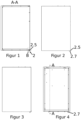
- eine Schnittdarstellung durch das Gehäuse entlang der Linie A-A in
Figur 4 ; - Figur 2
- eine Seitenansicht des Gehäuses bei maximal ausgefahrener Distanzhalteeinrichtung;
- Figur 3
- eine Seitenansicht des Gehäuses bei minimal ausgefahrener Distanzhalteeinrichtung;
- Figur 4
- eine Rückansicht des Gehäuses mit der Schnittlinie A-A zu
Figur 1 ; - Figur 5
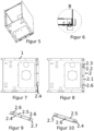
- perspektivisch von unten das Gehäuse mit der erfindungsgemäßen Distanzhalteeinrichtung;
- Figur 6
- eine Ausschnittsvergrößerung B gemäß
Figur 1 ; - Figur 7
- von unten das Gehäuse gemäß
Figur 5 bei maximal ausgefahrener Distanzhalteeinrichtung; - Figur 8
- von unten das Gehäuse gemäß
Figur 5 bei minimal ausgefahrener Distanzhalteeinrichtung; - Figur 9
- die in den
Figuren 1 bis 8 verwendete Ausführungsform der erfindungsgemäßen Schiene für unten geschlossene Gehäuse; und - Figur 10
- eine alternative Ausführungsform der erfindungsgemäßen Schiene für unten offene Gehäuse.
- Das in den Figuren dargestellte wandhängende Gehäuse besteht zunächst einmal in an sich bekannter Weise aus einem an einer Wand aufzuhängenden Korpus 1 und einer verstellbar am Korpus 1 gelagerten und mit der Wand in Kontakt stehenden Distanzhalteeinrichtung 2 zur Einstellung eines Abstandes zwischen dem Korpus 1 und der Wand, wobei die Distanzhalteeinrichtung 2 eine Schiene 2.1 aufweist und dass zur Verbindung der Schiene 2.1 mit dem Korpus Verbindungselemente 2.2, 2.3 vorgesehen sind. Die Verbindungselemente 2.2, 2.3 wirken dabei wie eine schiefe Ebene miteinander. Die Schiene 2.1 ist vorzugsweise aus Blech gebildet.
- Dabei ist bevorzugt vorgesehen, dass der Korpus 1 wahlweise quaderförmig und/oder als Gehäuse eines Heizgerätes, insbesondere eines mit Gas oder Öl betriebenen Heizgerätes, ausgebildet ist.
- Weiterhin ist bevorzugt vorgesehen, dass der Korpus 1 in aufgehängter Lage an seinem oberen Ende an Wandhaken hängend und/oder an seinem unteren, wandseitigen Ende mit der Distanzhalteeinrichtung 2 versehen ausgebildet ist.
- Unter dem Begriff "Kontakt" ist dabei, und im Unterschied zur Lösung gemäß der vorgenannten
DE 30 22 787 A1 , bei der ein hängender Kontakt realisiert ist, bevorzugt ein Anlagekontakt gemeint, d. h. auf die Distanzhalteeinrichtung 2 wirkt eine insbesondere horizontale Druckkraft ein. - Wesentlich für das erfindungsgemäße Gehäuse ist nun, dass eines der Verbindungselemente 2.2 als länglicher Schlitz ausgebildet ist, dass der Schlitz entlang einer ersten geraden Linie verläuft, die ihrerseits in aufgehängter Lage des Korpus 1 einerseits parallel zur Unterseite des Korpus und andererseits schräg zur Rückseite des Korpus verlaufend ausgebildet ist, dass ein Weiteres der Verbindungselemente 2.3 als den Schlitz durchgreifender Stift ausgebildet ist und dass der Stift entlang einer zweiten geraden Linie verläuft, die ihrerseits in aufgehängter Lage des Korpus 1 einerseits parallel zur Rückseite des Korpus und andererseits senkrecht zur Unterseite des Korpus verlaufend ausgebildet ist.
- Dabei ist bevorzugt vorgesehen, dass die Schiene 2.1 aus zwei zueinander abgewinkelt angeordneten Flächenstreifen 2.4, 2.5 gebildet ist. Dabei sind vorzugsweise die Flächenstreifen 2.4, 2.5 im rechten Winkel zueinander angeordnet. Weiterhin ist bevorzugt, dass in aufgehängter Lage des Korpus 1 einer der Flächenstreifen 2.4 flächenparallel zu einer Unterseite des Korpus 1 und der andere Flächenstreifen 2.5 flächenparallel zur wandseitigen Rückseite des Korpus 1 verlaufend ausgebildet ist und/oder dass an mindestens einem Flächenstreifen 2.4, 2.5 mindestens eine wahlweise den Korpus 1 oder die Wand kontaktierende Ausbuchtung 2.6 zur Reibungsreduzierung beim Einstellen der Distanzhalteeinrichtung 2 vorgesehen ist.
- Weiterhin ist bevorzugt, dass die erste gerade Linie in einem eine Selbsthemmung zwischen Stift und Schlitz ermöglichenden Winkel an der Schiene 2.1 verlaufend ausgebildet ist. Schließlich ist vorzugsweise an mindestens einem Ende der Schiene 2.1 eine Lasche 2.7 zum händischen Einstellen der Distanzhalteeinrichtung 2 angeordnet. Die Lösung gemäß
Figur 9 ist dabei für ein unten geschlossenes Gehäuse (wie in denFiguren 1 bis 8 dargestellt) und die Lösung gemäßFigur 10 für ein unten offenes Gehäuse (nicht extra dargestellt) vorgesehen. Vorteilhaft bezüglich des Komforts ist bei beiden Lösungen, dass die Lasche 2.7 zur Einstellung der Distanz nicht einsehbar sein muss, sondern rein haptisch erkennbar ist. - Das erfindungsgemäße wandhängende Gehäuse funktioniert wie folgt:
Zunächst wird der Korpus 1 an seinem oberen Ende an einer Wand aufgehängt, so dass der Flächenstreifen 2.5 die Wand über die beiden Ausbuchtungen 2.6 berührt. Durch Greifen und Bewegen der Lasche 2.7 kann die Schiene 2.1 verstellt werden, so dass sich die Verbindungselemente 2.2 und 2.3 relativ zueinander verschieben und der gewünschte Abstand zwischen dem unteren Ende des Korpus 1 und der Wand eingestellt werden kann. -
- 1
- Korpus
- 2
- Distanzhalteeinrichtung
- 2.1
- Schiene
- 2.2
- Verbindungselement
- 2.3
- Verbindungselement
- 2.4
- Flächenstreifen
- 2.5
- Flächenstreifen
- 2.6
- Ausbuchtung
- 2.7
- Lasche
Claims (6)
- Wandhängendes Gehäuse, umfassend einen an einer Wand aufzuhängenden Korpus (1) und eine verstellbar am Korpus (1) gelagerte und mit der Wand in Kontakt stehende Distanzhalteeinrichtung (2) zur Einstellung eines Abstandes zwischen dem Korpus (1) und der Wand, wobei die Distanzhalteeinrichtung (2) eine Schiene (2.1) aufweist und dass zur Verbindung der Schiene (2.1) mit dem Korpus Verbindungselemente (2.2, 2.3) vorgesehen sind,
dadurch gekennzeichnet,
dass eines der Verbindungselemente (2.2) als länglicher Schlitz ausgebildet ist, dass der Schlitz entlang einer ersten geraden Linie verläuft, die ihrerseits in aufgehängter Lage des Korpus (1) einerseits parallel zur Unterseite des Korpus und andererseits schräg zur Rückseite des Korpus verlaufend ausgebildet ist, dass ein Weiteres der Verbindungselemente (2.3) als den Schlitz durchgreifender Stift ausgebildet ist und dass der Stift entlang einer zweiten geraden Linie verläuft, die ihrerseits in aufgehängter Lage des Korpus (1) einerseits parallel zur Rückseite des Korpus und andererseits senkrecht zur Unterseite des Korpus verlaufend ausgebildet ist. - Wandhängendes Gehäuse nach Anspruch 1,
dadurch gekennzeichnet,
dass die Schiene (2.1) aus zwei zueinander abgewinkelt angeordneten Flächenstreifen (2.4, 2.5) gebildet ist. - Wandhängendes Gehäuse nach Anspruch 2,
dadurch gekennzeichnet,
dass die Flächenstreifen (2.4, 2.5) im rechten Winkel zueinander angeordnet sind. - Wandhängendes Gehäuse nach Anspruch 2 oder 3,
dadurch gekennzeichnet,
dass in aufgehängter Lage des Korpus (1) einer der Flächenstreifen (2.4) flächenparallel zu einer Unterseite des Korpus (1) und der andere Flächenstreifen (2.5) flächenparallel zur wandseitigen Rückseite des Korpus (1) verlaufend ausgebildet ist. - Wandhängendes Gehäuse nach einem der Ansprüche 2 bis 4, dadurch gekennzeichnet,
dass an mindestens einem Flächenstreifen (2.4, 2.5) mindestens eine wahlweise den Korpus (1) oder die Wand kontaktierende Ausbuchtung (2.6) zur Reibungsreduzierung beim Einstellen der Distanzhalteeinrichtung (2) vorgesehen ist. - Wandhängendes Gehäuse nach einem der Ansprüche 1 bis 5, dadurch gekennzeichnet,
dass die erste gerade Linie in einem eine Selbsthemmung zwischen Stift und Schlitz ermöglichenden Winkel an der Schiene (2.1) verlaufend ausgebildet ist.
Applications Claiming Priority (1)
| Application Number | Priority Date | Filing Date | Title |
|---|---|---|---|
| DE102019117042.7A DE102019117042A1 (de) | 2019-06-25 | 2019-06-25 | Wandhängendes Gehäuse |
Publications (3)
| Publication Number | Publication Date |
|---|---|
| EP3757464A1 EP3757464A1 (de) | 2020-12-30 |
| EP3757464B1 true EP3757464B1 (de) | 2024-12-18 |
| EP3757464C0 EP3757464C0 (de) | 2024-12-18 |
Family
ID=71111268
Family Applications (1)
| Application Number | Title | Priority Date | Filing Date |
|---|---|---|---|
| EP20180978.7A Active EP3757464B1 (de) | 2019-06-25 | 2020-06-19 | Wandhängendes gehäuse |
Country Status (2)
| Country | Link |
|---|---|
| EP (1) | EP3757464B1 (de) |
| DE (1) | DE102019117042A1 (de) |
Families Citing this family (1)
| Publication number | Priority date | Publication date | Assignee | Title |
|---|---|---|---|---|
| DE202022105683U1 (de) | 2021-10-21 | 2022-12-12 | Viessmann Climate Solutions Se | Wandhängendes Gehäuse |
Family Cites Families (11)
| Publication number | Priority date | Publication date | Assignee | Title |
|---|---|---|---|---|
| AT295076B (de) * | 1970-07-24 | 1971-12-27 | Fischer Kuehler Metall | Aufhänger für Wandschränke |
| DE2128940A1 (de) * | 1971-06-11 | 1973-01-04 | Winter Fa Jakob | Aufhaengevorrichtung fuer haengemoebel |
| DE2735095A1 (de) * | 1977-08-04 | 1979-02-15 | Heinze Fa R | Aufhaengevorrichtung fuer wandschraenke |
| DE2920390A1 (de) * | 1979-05-19 | 1980-11-27 | Grass Alfred Metallwaren | Montageelemente fuer einen haengeschrank |
| ES481649A1 (es) | 1979-06-18 | 1980-07-16 | Pietsch Tibor | Procedimiento de fabricacion continua de vidrio celular. |
| DE3033024A1 (de) * | 1979-09-03 | 1981-03-12 | Alfred Grass GmbH Metallwarenfabrik, Höchst, Vorarlberg | Aufhaengeschiene fuer haengeschraenke o.dgl.. |
| DE3011787A1 (de) | 1979-10-09 | 1981-04-23 | Alfred Grass GmbH Metallwarenfabrik, Höchst, Vorarlberg | Schrankaufhaenger |
| AT398270B (de) * | 1984-09-29 | 1994-11-25 | Heinze Richard Gmbh Co Kg | Möbelbeschlag |
| DD243853A1 (de) * | 1985-12-07 | 1987-03-18 | Naumburg Metallwaren | Haengejustierbeschlag |
| DE3909957C2 (de) * | 1989-03-27 | 1997-07-17 | E Norm Beschlag Gmbh | Vorrichtung zum Aufhängen von Schränken |
| DE202011108342U1 (de) * | 2011-11-28 | 2012-02-15 | Oventrop Gmbh & Co. Kg | Montagekasten für verteilerlose Fußbodenheizung |
-
2019
- 2019-06-25 DE DE102019117042.7A patent/DE102019117042A1/de active Pending
-
2020
- 2020-06-19 EP EP20180978.7A patent/EP3757464B1/de active Active
Also Published As
| Publication number | Publication date |
|---|---|
| EP3757464A1 (de) | 2020-12-30 |
| DE102019117042A1 (de) | 2020-12-31 |
| EP3757464C0 (de) | 2024-12-18 |
Similar Documents
| Publication | Publication Date | Title |
|---|---|---|
| DE202004000652U1 (de) | Scharnier | |
| EP3344841B1 (de) | Bandseitige fingerschutzvorrichtung | |
| EP1934421B1 (de) | Beschlag zum schwenkbaren befestigen einer frontklappe an einem möbelschrank | |
| WO2018204956A1 (de) | Möbelantrieb | |
| EP1653031B1 (de) | Falttürenscharnier | |
| EP3825503A1 (de) | Dichtungsvorrichtung einer schiebetür | |
| EP3103948A1 (de) | Band für eine tür oder ein fenster | |
| DE102010004772B3 (de) | Türband für Aluminiumtüren | |
| EP3757464B1 (de) | Wandhängendes gehäuse | |
| EP3387954B1 (de) | Aufhängevorrichtung zur aufhängung eines möbels an einer wand und verwendung einer solchen aufhängevorrichtung | |
| CH675275A5 (de) | Beschlag fuer schiebetueren. | |
| DE3610102A1 (de) | Viergelenk-moebelscharnier | |
| DE202009016669U1 (de) | Möbel, Möbelteil und Vorrichtung zur Verbindung eines Frontbauteils eines Möbelteils | |
| DE10006587A1 (de) | Verstellbares Scharnier | |
| EP3666120B1 (de) | Schubladenfront-verbindungsvorrichtung und schublade | |
| DE8714788U1 (de) | Faltwand für Badewannen, Duschwannen o. dgl. | |
| DE102014007699B3 (de) | Schwingscharnier für ein Fenster, insbesondere Wohndachfenster | |
| DE10313842B4 (de) | Schranktür | |
| EP3073039B1 (de) | Gelenkbandanordnung | |
| EP3871575A1 (de) | Scharnier | |
| EP2615232A2 (de) | Beschlaganordnung | |
| DE102006000758B4 (de) | Möbelscharnier | |
| DE29720659U1 (de) | Vorrichtung zum Abdichten des unteren Spaltes einer Tür | |
| DE10238631B4 (de) | Einachsscharnier | |
| EP1876319B1 (de) | Gleitfuehrung fuer Schiebefluegel oder Abstellschiebefluegel |
Legal Events
| Date | Code | Title | Description |
|---|---|---|---|
| PUAI | Public reference made under article 153(3) epc to a published international application that has entered the european phase |
Free format text: ORIGINAL CODE: 0009012 |
|
| STAA | Information on the status of an ep patent application or granted ep patent |
Free format text: STATUS: THE APPLICATION HAS BEEN PUBLISHED |
|
| AK | Designated contracting states |
Kind code of ref document: A1 Designated state(s): AL AT BE BG CH CY CZ DE DK EE ES FI FR GB GR HR HU IE IS IT LI LT LU LV MC MK MT NL NO PL PT RO RS SE SI SK SM TR |
|
| AX | Request for extension of the european patent |
Extension state: BA ME |
|
| STAA | Information on the status of an ep patent application or granted ep patent |
Free format text: STATUS: REQUEST FOR EXAMINATION WAS MADE |
|
| 17P | Request for examination filed |
Effective date: 20210616 |
|
| RBV | Designated contracting states (corrected) |
Designated state(s): AL AT BE BG CH CY CZ DE DK EE ES FI FR GB GR HR HU IE IS IT LI LT LU LV MC MK MT NL NO PL PT RO RS SE SI SK SM TR |
|
| RAP1 | Party data changed (applicant data changed or rights of an application transferred) |
Owner name: VIESSMANN CLIMATE SOLUTIONS SE |
|
| STAA | Information on the status of an ep patent application or granted ep patent |
Free format text: STATUS: EXAMINATION IS IN PROGRESS |
|
| 17Q | First examination report despatched |
Effective date: 20230103 |
|
| GRAP | Despatch of communication of intention to grant a patent |
Free format text: ORIGINAL CODE: EPIDOSNIGR1 |
|
| STAA | Information on the status of an ep patent application or granted ep patent |
Free format text: STATUS: GRANT OF PATENT IS INTENDED |
|
| INTG | Intention to grant announced |
Effective date: 20240802 |
|
| GRAS | Grant fee paid |
Free format text: ORIGINAL CODE: EPIDOSNIGR3 |
|
| GRAA | (expected) grant |
Free format text: ORIGINAL CODE: 0009210 |
|
| STAA | Information on the status of an ep patent application or granted ep patent |
Free format text: STATUS: THE PATENT HAS BEEN GRANTED |
|
| AK | Designated contracting states |
Kind code of ref document: B1 Designated state(s): AL AT BE BG CH CY CZ DE DK EE ES FI FR GB GR HR HU IE IS IT LI LT LU LV MC MK MT NL NO PL PT RO RS SE SI SK SM TR |
|
| REG | Reference to a national code |
Ref country code: CH Ref legal event code: EP |
|
| REG | Reference to a national code |
Ref country code: DE Ref legal event code: R096 Ref document number: 502020009982 Country of ref document: DE |
|
| REG | Reference to a national code |
Ref country code: IE Ref legal event code: FG4D Free format text: LANGUAGE OF EP DOCUMENT: GERMAN |
|
| U01 | Request for unitary effect filed |
Effective date: 20241218 |
|
| U07 | Unitary effect registered |
Designated state(s): AT BE BG DE DK EE FI FR IT LT LU LV MT NL PT RO SE SI Effective date: 20250102 |
|
| PG25 | Lapsed in a contracting state [announced via postgrant information from national office to epo] |
Ref country code: HR Free format text: LAPSE BECAUSE OF FAILURE TO SUBMIT A TRANSLATION OF THE DESCRIPTION OR TO PAY THE FEE WITHIN THE PRESCRIBED TIME-LIMIT Effective date: 20241218 |
|
| PG25 | Lapsed in a contracting state [announced via postgrant information from national office to epo] |
Ref country code: NO Free format text: LAPSE BECAUSE OF FAILURE TO SUBMIT A TRANSLATION OF THE DESCRIPTION OR TO PAY THE FEE WITHIN THE PRESCRIBED TIME-LIMIT Effective date: 20250318 |
|
| PG25 | Lapsed in a contracting state [announced via postgrant information from national office to epo] |
Ref country code: GR Free format text: LAPSE BECAUSE OF FAILURE TO SUBMIT A TRANSLATION OF THE DESCRIPTION OR TO PAY THE FEE WITHIN THE PRESCRIBED TIME-LIMIT Effective date: 20250319 |
|
| PG25 | Lapsed in a contracting state [announced via postgrant information from national office to epo] |
Ref country code: RS Free format text: LAPSE BECAUSE OF FAILURE TO SUBMIT A TRANSLATION OF THE DESCRIPTION OR TO PAY THE FEE WITHIN THE PRESCRIBED TIME-LIMIT Effective date: 20250318 |
|
| RAP2 | Party data changed (patent owner data changed or rights of a patent transferred) |
Owner name: VIESSMANN HOLDING INTERNATIONAL GMBH |
|
| U1K | Transfer of rights of the unitary patent after the registration of the unitary effect |
Owner name: VIESSMANN HOLDING INTERNATIONAL GMBH; DE |
|
| U20 | Renewal fee for the european patent with unitary effect paid |
Year of fee payment: 6 Effective date: 20250520 |
|
| PG25 | Lapsed in a contracting state [announced via postgrant information from national office to epo] |
Ref country code: SM Free format text: LAPSE BECAUSE OF FAILURE TO SUBMIT A TRANSLATION OF THE DESCRIPTION OR TO PAY THE FEE WITHIN THE PRESCRIBED TIME-LIMIT Effective date: 20241218 |
|
| PG25 | Lapsed in a contracting state [announced via postgrant information from national office to epo] |
Ref country code: PL Free format text: LAPSE BECAUSE OF FAILURE TO SUBMIT A TRANSLATION OF THE DESCRIPTION OR TO PAY THE FEE WITHIN THE PRESCRIBED TIME-LIMIT Effective date: 20241218 |
|
| PG25 | Lapsed in a contracting state [announced via postgrant information from national office to epo] |
Ref country code: ES Free format text: LAPSE BECAUSE OF FAILURE TO SUBMIT A TRANSLATION OF THE DESCRIPTION OR TO PAY THE FEE WITHIN THE PRESCRIBED TIME-LIMIT Effective date: 20241218 |
|
| PG25 | Lapsed in a contracting state [announced via postgrant information from national office to epo] |
Ref country code: IS Free format text: LAPSE BECAUSE OF FAILURE TO SUBMIT A TRANSLATION OF THE DESCRIPTION OR TO PAY THE FEE WITHIN THE PRESCRIBED TIME-LIMIT Effective date: 20250418 |
|
| PG25 | Lapsed in a contracting state [announced via postgrant information from national office to epo] |
Ref country code: SK Free format text: LAPSE BECAUSE OF FAILURE TO SUBMIT A TRANSLATION OF THE DESCRIPTION OR TO PAY THE FEE WITHIN THE PRESCRIBED TIME-LIMIT Effective date: 20241218 |
|
| PG25 | Lapsed in a contracting state [announced via postgrant information from national office to epo] |
Ref country code: CZ Free format text: LAPSE BECAUSE OF FAILURE TO SUBMIT A TRANSLATION OF THE DESCRIPTION OR TO PAY THE FEE WITHIN THE PRESCRIBED TIME-LIMIT Effective date: 20241218 |
|
| PLBE | No opposition filed within time limit |
Free format text: ORIGINAL CODE: 0009261 |
|
| STAA | Information on the status of an ep patent application or granted ep patent |
Free format text: STATUS: NO OPPOSITION FILED WITHIN TIME LIMIT |
|
| REG | Reference to a national code |
Ref country code: CH Ref legal event code: L10 Free format text: ST27 STATUS EVENT CODE: U-0-0-L10-L00 (AS PROVIDED BY THE NATIONAL OFFICE) Effective date: 20251029 |
|
| 26N | No opposition filed |
Effective date: 20250919 |
|
| REG | Reference to a national code |
Ref country code: CH Ref legal event code: H13 Free format text: ST27 STATUS EVENT CODE: U-0-0-H10-H13 (AS PROVIDED BY THE NATIONAL OFFICE) Effective date: 20260127 |
|
| PG25 | Lapsed in a contracting state [announced via postgrant information from national office to epo] |
Ref country code: MC Free format text: LAPSE BECAUSE OF FAILURE TO SUBMIT A TRANSLATION OF THE DESCRIPTION OR TO PAY THE FEE WITHIN THE PRESCRIBED TIME-LIMIT Effective date: 20241218 |
|
| GBPC | Gb: european patent ceased through non-payment of renewal fee |
Effective date: 20250619 |
|
| PG25 | Lapsed in a contracting state [announced via postgrant information from national office to epo] |
Ref country code: GB Free format text: LAPSE BECAUSE OF NON-PAYMENT OF DUE FEES Effective date: 20250619 |
|
| PG25 | Lapsed in a contracting state [announced via postgrant information from national office to epo] |
Ref country code: IE Free format text: LAPSE BECAUSE OF NON-PAYMENT OF DUE FEES Effective date: 20250619 |