EP3756520B1 - Toilettenbrille mit höhenverstellbaren abstandhaltern - Google Patents
Toilettenbrille mit höhenverstellbaren abstandhaltern Download PDFInfo
- Publication number
- EP3756520B1 EP3756520B1 EP20178643.1A EP20178643A EP3756520B1 EP 3756520 B1 EP3756520 B1 EP 3756520B1 EP 20178643 A EP20178643 A EP 20178643A EP 3756520 B1 EP3756520 B1 EP 3756520B1
- Authority
- EP
- European Patent Office
- Prior art keywords
- cover
- rotary body
- spacers
- toilet seat
- base
- Prior art date
- Legal status (The legal status is an assumption and is not a legal conclusion. Google has not performed a legal analysis and makes no representation as to the accuracy of the status listed.)
- Active
Links
Images





Classifications
-
- A—HUMAN NECESSITIES
- A47—FURNITURE; DOMESTIC ARTICLES OR APPLIANCES; COFFEE MILLS; SPICE MILLS; SUCTION CLEANERS IN GENERAL
- A47K—SANITARY EQUIPMENT; ACCESSORIES THEREFOR, e.g. TOILET ACCESSORIES
- A47K13/00—Seats or covers for all kinds of closets
- A47K13/04—Buffers for seats
-
- A—HUMAN NECESSITIES
- A47—FURNITURE; DOMESTIC ARTICLES OR APPLIANCES; COFFEE MILLS; SPICE MILLS; SUCTION CLEANERS IN GENERAL
- A47K—SANITARY EQUIPMENT; ACCESSORIES THEREFOR, e.g. TOILET ACCESSORIES
- A47K13/00—Seats or covers for all kinds of closets
- A47K13/24—Parts or details not covered in, or of interest apart from, groups A47K13/02 - A47K13/22
- A47K13/28—Adjustably-mounted seats or covers
Definitions
- the present invention relates to toilet seats with height-adjustable spacers.
- a toilet comprises a toilet bowl 01 and a toilet seat arrangement, the toilet seat arrangement in turn being divided into a seat 02 and a seat 03.
- the toilet seat assembly is pivotally connected to the toilet bowl.
- spacers 04 are usually provided on an underside of the toilet seat 02, namely two front and two rear spacers. After the toilet seat 02 has been lowered, the spacers 04 are supported on an upper side of the toilet bowl 01.
- the toilet pan 01 is formed of ceramics by firing, there is unevenness on the surface of the toilet pan 01 due to expansion/contraction during firing, which differs from surface to surface.
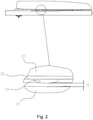
- the toilet seat 02 has been lowered, there is a gap H between the front spacers 04 and the rear spacers 04 and the upper side of the toilet bowl 01, as shown in FIG 2 is shown.
- a gap is formed between the front spacers 04 and the surface of the toilet bowl, so that the front end of the toilet lid assembly is bent upward, affecting the appearance of the toilet.
- the front spacers 04 are generally made slightly thinner by the manufacturer, so that when the front spacers rest on the surface of the toilet bowl, the rear spacers 04 also rest against it as much as possible. However, because of the aforementioned unevenness on the surface of the toilet bowl, there is more or less a gap H between the rear spacers and the surface of the toilet bowl.
- the most stressed point is in the rear part of the toilet seat 02 when sitting on the toilet seat 02. Therefore, the gap H between the rear spacers 04 and the surface of the toilet bowl 01 results in a large deformation in the rear part of the toilet seat 02, so that the toilet seat 02 is very prone to breakage at this point.
- a toilet seat with four height-adjustable spacers is known, which are arranged symmetrically at the front and rear on the underside of a seat body.
- the DE 198 10 858 A1 also discloses a toilet seat with height-adjustable spacers.
- the spacers are adjusted using a rotary knob that is connected to the spacers via a toothed belt.
- the object of the invention is to overcome the disadvantages mentioned.
- the height of the rear spacers can be adjusted according to the distance between the rear spacers and the toilet bowl after lowering the toilet seat, so that the rear spacers can also be supported on the top of the toilet bowl.
- the gap between the rear spacers and the toilet bowl is eliminated, so that the front and rear spacers at the bottom of the toilet seat are stably supported on the toilet bowl to prevent breakage caused by the deformation in the form of sagging of the toilet seat under the user's weight to avoid.
- the spacers are always connected to the toilet seat during adjustment without having to be removed from it, which is very convenient.
- a toilet seat with height-adjustable spacers is usually arranged on a toilet bowl during use.
- the side of the toilet that faces a human body is referred to as the front side and defines the side facing away from the human body as the rear side.
- the toilet seat includes a seat body 10 and a plurality of (four in this embodiment) spacers 20 located therebelow.
- the spacers 20 are divided into a front group of spacers symmetrically arranged in a left part and a right part of a front portion of a bottom of the seat body 10 and referred to as front or front spacers, and a rear group of spacers arranged symmetrically in a left part and a right part of a central portion of the underside of the eyeglass body and referred to as rear or rear spacers.
- the height of at least the rear set of spacers 20 can be adjusted to support the top of the toilet bowl.
- the rear spacers are adjustable, but it should be noted that the front spacers may also be adjustable in height.
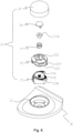
- FIG. 5 to 8 show a spacer whose height is adjustable, also referred to as an adjustable spacer, which in this embodiment is a rear spacer.
- An adjustable spacer 20 includes a lid 21.
- a mounting seat 12 is provided on the underside of the goggle body 10.
- the cover 21 is arranged in the mounting receptacle 12 so that it can be moved out vertically. As the cover 21 is moved out of the mounting receptacle 12, the height of the spacer increases steadily. On the other hand, while the cover 21 is being moved into the mounting receptacle 12, the height of the spacer steadily decreases.
- the cover 21 can be rotated and the rotation causes a vertical lifting or lowering.
- the cover 21 is rotatably mounted in the mounting mount 12 .
- the lid 21 is formed as a case with an open top, and the opening of the lid is inserted into the mounting seat 12 .
- the adjustable spacer 20 further comprises a rotating body 22 and a base 23 which are placed one above the other.
- the base 23 is arranged in the mounting seat 12 .
- the base 23 is held or directly fastened in the circumferential direction in relation to the mounting receptacle 12 by the engagement of a stopper in a limiting groove.
- the rotary body 22 is accommodated in the lid 21 and connected thereto.
- the rotating body 22 is held in the circumferential direction with respect to the cover 21 or directly fastened by the engagement of a stopper in a limiting groove.
- a two-stage lower inclined surface arranged rotationally symmetrically about its center, a head part being connected to a foot part of the two-stage lower inclined surface and the lower inclined surface being provided with a lower toothing 232 .
- a two-stage upper inclined surface is provided on an upper side of the rotating body 22, arranged rotationally symmetrically about its center, with a head part also being connected to a foot part of the two-stage upper inclined surface, with the upper inclined surface being provided with an upper toothing 222 corresponding to the lower toothing , and wherein the lower spline 232 and the upper spline 222 are rotatably meshed.
- the rotating body 22 rotates in a direction in which the upper and lower inclined surfaces overlap less, the lower serration and the upper serration 222 mesh with each other, and the rotating body 22 rises, so that the lid 21 is raised.
- the rotary body 22 rotates in a direction in which the upper and lower Cover inclined surface more, engage the lower toothing and the upper toothing 222 and the rotating body 22 descends, so that the cover 21 is lower.
- the adjustable spacer 20 further includes an elastic member 24.
- the elastic member 24 is stretched between the rotating body 22 and the base 23 so that the upper serration 222 and the lower serration 232 are firmly meshed.
- the lower toothing 232 and the upper toothing 222 are arranged obliquely in such a way that one side of the respective toothing is aligned vertically and the other side is inclined, as in FIG 9 shown.
- the cover is gradually lifted out of the mounting seat, ie, the sloping surface of the upper gear 222 rises along the sloping surface of the lower gear 232 to raise the rotary body and the cover.
- a stop 224 from an edge of the rotating body 22 down and a curved spiral restricting groove 234 is provided on an outer edge of the base 23, and the rotary body moves the stopper 224 along the spiral restricting groove 234 when rotated.
- Two ends of the spiral restriction groove 234 each form a barrier.
- the lid is lowered to the lowest position when the stop 224 abuts the barrier at the lower end of the spiral constraint groove.
- the lid is raised to the highest position when the stopper abuts the barrier at the higher end of the spiral restraining groove. That is, the highest and lowest positions of the rotary body 22 are restricted by the cooperation of the stopper 224 and the spiral restriction groove 234 .
- a stud 236 is provided at a central portion of the base 23, a stud 236 is provided.
- the stud 236 penetrates the rotary body 22, and one end of the stud is screwed to a limit nut 238.
- the elastic member 24 is stretched between the rotating body 22 and the restriction nut 238 .
- a recess 226 is preferably provided on an end face of the rotating body 22 which faces away from the base.
- the stud 236 is arranged in the recess 226 .
- the adjustable spacer also includes a cover cap 26 to cover the recess.
- the spacer in the figures 11 and 12 is not within the meaning of the present invention.
- the structure of the toilet seat with adjustable height spacers is different from that in Figures 4 to 10 shown embodiment according to the invention in that the rotary body 22a of the height-adjustable spacer comprises a connecting portion 228 and a screw 229.
- the connecting portion 228 is connected to the lid 21, and they are circumferentially held relative to each other or directly fixed to each other.
- the rotary knob 22a is accommodated in the cover 21 in this case.
- a screw hole 14 is formed in the mounting seat 12 of the eyeglass body 10.
- the screw 229 is in rotational connection with the screw hole 14 .
- the rotary body 22a When the lid 21 is rotated, the rotary body 22a is rotated along with it, so that the screw 229 is screwed in or unscrewed by the interaction of the screw 229 and the screw hole 14 and then the lid 21 moves in or out of the mounting seat 12 , to cause a height adjustment of the lid 21.
Landscapes
- Health & Medical Sciences (AREA)
- Public Health (AREA)
- Toilet Supplies (AREA)
Description
- Die vorliegende Erfindung betrifft Toilettenbrille mit höhenverstellbaren Abstandhaltern.
- Es ist aus
Fig. 1 ersichtlich, dass eine Toilette ein Toilettenbecken 01 und eine Toilettendeckelanordnung umfasst, wobei die Toilettendeckelanordnung wiederum in eine Brille 02 und einen Deckel 03 unterteilt ist. Die Toilettendeckelanordnung ist schwenkbar mit dem Toilettenbecken verbunden. An einer Unterseite der Toilettenbrille 02 sind üblicherweise vier Abstandhalter 04 vorgesehen, und zwar zwei vordere und zwei hintere Abstandhalter. Die Abstandhalter 04 stützen sich nach dem Absenken der Toilettenbrille 02 auf einer Oberseite des Toilettenbeckens 01. - Da das Toilettenbecken 01 aus Keramik in einem Brennvorgang geformt ist, besteht auf der Oberfläche des Toilettenbeckens 01 wegen der Ausdehnung/Schrumpfung während des Brennens eine Unebenheit, die von Oberfläche zu Oberfläche unterschiedlich ist. So entsteht nach dem Absenken der Toilettenbrille 02 ein Spalt H zwischen den vorderen Abstandhaltern 04 bzw. den hinteren Abstandhaltern 04 und der oberen Seite des Toilettenbeckens 01, wie es in
Fig. 2 gezeigt ist. Sollen die hinteren Abstandhalter 04 auf der Oberfläche des Toilettenbeckens 01 anliegen, entsteht ein Spalt zwischen den vorderen Abstandhaltern 04 und der Oberfläche des Toilettenbeckens, so dass das vordere Ende der Toilettendeckelanordnung nach oben gebogen wird, was das Aussehen der Toilette beeinflusst. Daher werden in der Regel die vorderen Abstandhalter 04 vom Hersteller geringfügig dünner ausgebildet, so dass bei dem Anliegen der vorderen Abstandhalter an der Oberfläche des Toilettenbeckens die hinteren Abstandhalter 04 auch möglichst daran anliegen. Allerdings besteht wegen der vorgenannten Unebenheiten an der Oberfläche des Toilettenbeckens mehr oder weniger ein Spalt H zwischen den hinteren Abstandhaltern und der Oberfläche des Toilettenbeckens. - Wie in
Fig. 3 zu sehen ist, befindet sich der am stärksten belastete Punkt in dem hinteren Teil der Toilettenbrille 02, wenn man auf der Toilettenbrille 02 sitzt. Daher führt der Spalt H zwischen den hinteren Abstandhaltern 04 und der Oberfläche des Toilettenbeckens 01 zu einer großen Verformung in dem hinteren Teil der Toilettenbrille 02, so dass die Toilettenbrille 02 an dieser Stelle sehr bruchanfällig ist. - Aus diesem Grund ist es üblich, für den Kunden mehrere Gruppen von Abstandhaltern mit unterschiedlicher Höhe vorzusehen, so dass er nach tatsächlichem Bedarf eine geeignete Gruppe von Abstandhaltern benutzt. Daraus ergeben sich jedoch zwei Probleme: Erstens muss der Kunde die vormontierten Abstandhalter von der Toilettenbrille aufwändig entnehmen und die neuen Abstandhalter mit geeigneter Höhe montieren, mehrfach probieren und verstellen. Zweitens kann der Spalt dadurch nicht vollständig beseitigt werden, da der Verformungsgrad der Keramik nicht vorhersagbar ist und die Höhen der zusätzlichen Abstandhalter nicht genau, sondern nur grob zu der erwünschten Höhe passen.
- Aus der
CN 203873677 U und derUS 3, 490, 082 ist jeweils eine Toilettenbrille mit vier höhenverstellbaren Abstandhaltern bekannt, die symmetrisch vorne und hinten an der Unterseite eines Brillenkörpers angeordnet sind. - Die
DE 198 10 858 A1 offenbart ebenfalls eine Toilettenbrille mit höhenverstellbaren Abstandhaltern. Die Abstandhalter werden über einen Drehknopf eingestellt, der über einen Zahnriemen mit den Abstandhaltern verbunden ist. - Die Einstellbarkeit der bekannten Abstandhalter ist kompliziert (
US 3,490,082 ) oder erfolgt für alle Abstandhalter einheitlich (CN 203873677 U ;DE 198 10 858 A1 ). - Der Erfindung liegt die Aufgabe zugrunde, die genannten Nachteile zu überwinden.
- Diese Aufgabe wird gelöst durch eine Toilettenbrille mit den Merkmalen des Patentanspruchs 1.
- Da die hinteren Abstandhalter hinsichtlich ihrer Höhe verstellbar sind, kann die Höhe der hinteren Abstandhalter gemäß dem Abstand zwischen den hinteren Abstandhaltern und dem Toilettenbecken nach dem Absenken der Toilettenbrille eingestellt werden, so dass die hinteren Abstandhalter ebenfalls auf der Oberseite des Toilettenbeckens abgestützt werden können. So wird der Spalt zwischen den hinteren Abstandhaltern und dem Toilettenbecken eliminiert, so dass die vorderen und hinteren Abstandhalter an der Unterseite der Toilettenbrille stabil auf dem Toilettenbecken abgestützt werden, um durch die Verformung in Form eines Durchbiegens der Toilettenbrille unter dem Gewicht des Benutzers bedingten Bruch wirksam zu vermeiden. Darüber hinaus sind die Abstandhalter bei der Verstellung stets mit der Toilettenbrille verbunden, ohne von ihr abgenommen werden zu müssen, was sehr günstig ist.
- Im Folgenden wird die Erfindung anhand von Ausführungsbeispielen im Zusammenhang mit den Zeichnungen näher beschrieben.
-
Figur 1 zeigt eine schematische Ansicht einer herkömmlichen Toilette. -
Figur 2 zeigt eine schematische Seitenansicht der Toilette nachFig. 1 bei einer abgesenkten Toilettendeckelanordnung. -
Figur 3 zeigt eine schematische Seitenansicht der Toilette nachFig. 1 bei einem geöffneten Deckel. -
Figur 4 zeigt eine schematische perspektivische Explosionsansicht einer erfindungsgemäßen Toilettenbrille mit höhenverstellbaren Abstandhaltern gemäß einem ersten Ausführungsbeispiel. -
Figur 5 zeigt eine schematische Explosionsansicht eines hinteren Abstandhalters der Toilettenbrille nachFig.4 . -
Figur 6 zeigt eine weitere schematische Explosionsansicht eines hinteren Abstandhalters der Toilettenbrille nachFig. 4 . -
Figur 7 zeigt eine schematische Darstellung eines montierten hinteren Abstandhalters der Toilettenbrille nachFig. 4 . -
Figur 8 zeigt einen schematischen Schnitt eines hinteren Abstandhalters der Toilettenbrille nachFig. 4 . -
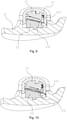
Figur 9 zeigt eine schematische Ansicht eines erhöhten hinteren Abstandhalters der Toilettenbrille nachFig. 4 . -
Figur 10 zeigt eine schematische Ansicht eines hinteren Abstandhalters der Toilettenbrille nachFig. 4 , wobei der Drehkörper und die Basis voneinander gelöst sind. -
Figur 11 zeigt eine schematische perspektivische Explosionsansicht einer Toilettenbrille mit höhenverstellbaren Abstandhaltern (nicht durch die beanspruchte Erfindung abgedeckt). -
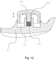
Figur 12 zeigt einen schematischen Schnitt eines hinteren Abstandhalters der Toilettenbrille nachFig. 11 . - Aus
Fig. 3 ist ersichtlich, dass eine Toilettenbrille mit höhenverstellbaren Abstandhaltern bei der Benutzung üblicherweise auf einem Toilettenbecken angeordnet ist. Um die Beschreibung zu vereinfachen, wird die einem menschlichen Körper zugewandte Seite der Toilette als vordere Seite und die dem menschlichen Körper abgewandte Seite als hintere Seite definiert. Die Toilettenbrille umfasst einen Brillenkörper 10 und mehrere (in diesem Ausführungsbeispiel vier) darunter befindliche Abstandhalter 20. Die Abstandhalter 20 sind in eine vordere Gruppe von Abstandhaltern, die symmetrisch in einem linken Teil und einem rechten Teil eines vorderen Abschnitts einer Unterseite des Brillenkörpers 10 angeordnet sind und als vorderseitige oder vordere Abstandhalter bezeichnet sind, und eine hintere Gruppe von Abstandhaltern, die symmetrisch in einem linken Teil und einem rechten Teil eines mittleren Abschnitts der Unterseite des Brillenkörpers angeordnet sind und als hinterseitige oder hintere Abstandhalter bezeichnet sind, unterteilt. Die Höhe mindestens der hinteren Gruppe von Abstandhaltern 20 kann verstellt werden, um sich auf der oberen Seite des Toilettenbeckens abzustützen. Bei diesem Ausführungsbeispiel sind die hinteren Abstandhalter verstellbar, aber es sei darauf hingewiesen, dass die vorderen Abstandhalter ebenfalls höhenverstellbar ausgebildet sein können. - Die
Fig. 5 bis Fig. 8 zeigen einen Abstandhalter, dessen Höhe verstellbar ist und der auch als verstellbarer Abstandhalter bezeichnet wird, wobei es sich bei diesem Ausführungsbeispiel um einen hinteren Abstandhalter handelt. Ein verstellbarer Abstandhalter 20 umfasst einen Deckel 21. Eine Montageaufnahme 12 ist an der Unterseite des Brillenkörpers 10 vorgesehen. Der Deckel 21 ist senkrecht herausbeweglich in der Montageaufnahme 12 angeordnet. Während des Herausbewegens des Deckels 21 aus der Montageaufnahme 12 nimmt die Höhe des Abstandhalters stetig zu. Dagegen nimmt während des Hineinbewegens des Deckels 21 in die Montageaufnahme 12 die Höhe des Abstandhalters stetig ab. - Bei diesem Ausführungsbeispiel ist der Deckel 21 drehbar und es erfolgt durch die Drehung eine senkrechte Hebung bzw. Senkung. Der Deckel 21 ist drehbar in der Montageaufnahme 12 gelagert. Der Deckel 21 ist als Gehäuse mit einer offenen Oberseite ausgebildet, und die Öffnung des Deckels ist in die Montageaufnahme 12 eingesteckt. Der verstellbare Abstandhalter 20 umfasst weiterhin einen Drehkörper 22 und eine Basis 23, die übereinander angeordnet sind. Die Basis 23 ist in der Montageaufnahme 12 angeordnet. Durch das Eingreifen eines Anschlags in eine Begrenzungsnut ist die Basis 23 in Umfangsrichtung in Bezug auf die Montageaufnahme 12 gehalten oder unmittelbar befestigt. Der Drehkörper 22 ist in dem Deckel 21 aufgenommen und damit verbunden. Gleichermaßen ist durch das Eingreifen eines Anschlags in eine Begrenzungsnut der Drehkörper 22 in Umfangsrichtung in Bezug auf den Deckel 21 gehalten oder unmittelbar befestigt. An einer Unterseite der Basis 23 ist eine um ihr Zentrum drehsymmetrisch angeordnete zweistufige untere Schrägfläche vorgesehen, wobei ein Kopfteil mit einem Fußteil der zweistufigen unteren Schrägfläche verbunden ist und die untere Schrägfläche mit einer unteren Verzahnung 232 versehen ist. Der Schrägfläche entsprechend ist an einer Oberseite des Drehkörpers 22 eine um sein Zentrum drehsysmmetrisch angeordnete zweistufige obere Schrägfläche vorgesehen, wobei ein Kopfteil mit einem Fußteil der zweistufigen oberen Schrägfläche ebenfalls verbunden ist, wobei der unteren Verzahnung entsprechend die obere Schrägfläche mit einer oberen Verzahnung 222 versehen ist, und wobei die untere Verzahnung 232 und obere Verzahnung 222 drehbar ineinander greifen. Wenn sich der Drehkörper 22 in einer Richtung dreht, in der sich die obere und untere Schrägfläche weniger überdecken, greifen die untere Verzahnung und die obere Verzahnung 222 ineinander und der Drehkörper 22 steigt auf, so dass der Deckel 21 erhöht wird. Wenn sich der Drehkörper 22 in einer Richtung dreht, in der sich die obere und untere Schrägfläche mehr überdecken, greifen die untere Verzahnung und die obere Verzahnung 222 ineinander und der Drehkörper 22 steigt ab, so dass der Deckel 21 niedriger wird.
- Vorzugsweise umfasst der verstellbare Abstandhalter 20 ferner ein elastisches Element 24. Das elastische Element 24 ist zwischen dem Drehkörper 22 und der Basis 23 gespannt, so dass die obere Verzahnung 222 und die untere Verzahnung 232 fest ineinander greifend verbunden sind. Die untere Verzahnung 232 und die obere Verzahnung 222 sind derart schräg angeordnet, dass die eine Seite der jeweiligen Verzahnung senkrecht ausgerichtet und die andere Seite geneigt ist, wie in
Fig. 9 gezeigt. Bei der Drehung des Drehkörpers in der Neigungsrichtung der Verzahnung wird der Deckel allmählich aus der Montageaufnahme gehoben, d. h. die Schrägfläche der oberen Verzahnung 222 steigt entlang der Schrägfläche der unteren Verzahnung 232 auf, um den Drehkörper und den Deckel zu erhöhen. Wenn dagegen die senkrechten Seiten der oberen Verzahnung 222 und der unteren Verzahnung 232 aneinander anliegen, wird die Position dadurch gehalten, dass der Drehkörper 22 in der entgegengesetzten Richtung nicht drehbar ist und der Deckel 21 auf einer Sollhöhe gehalten wird. AusFig. 10 ist ersichtlich, dass durch das Hochziehen des Deckels und des Drehkörpers gegen die Vorspannung des elastischen Elements 24 die obere Verzahnung 222 und die untere Verzahnung 232 voneinander entkoppelt werden können, und danach der Drehkörper 22 in der entgegengesetzten Richtung gedreht werden kann. Nach der Freigabe des Deckels und des Drehkörpers greifen unter der Vorspannung des elastischen Elements 24 die obere Verzahnung 222 und die untere Verzahnung 232 wieder ineinander, um eine Absenkung zu erzielen. - Es ist aus
Fig. 5 und6 ersichtlich, dass sich ein Anschlag 224 von einem Rand des Drehkörpers 22 nach unten erstreckt und an einem äußeren Rand der Basis 23 eine gebogene spiralförmige Begrenzungsnut 234 vorgesehen ist, wobei der Drehkörper bei der Drehung den Anschlag 224 entlang der spiralförmigen Begrenzungsnut 234 bewegt. Zwei Enden der spiralförmigen Begrenzungsnut 234 bilden jeweils eine Barriere aus. Der Deckel ist bis zu der niedrigsten Position abgesenkt, wenn der Anschlag 224 an der Barriere am niedrigeren Ende der spiralförmigen Begrenzungsnut anliegt. Der Deckel ist bis zu der höchsten Position angehoben, wenn der Anschlag an der Barriere am höheren Ende der spiralförmigen Begrenzungsnut anliegt. Das heißt, die höchste und niedrigste Position des Drehkörpers 22 werden durch die Zusammenwirkung des Anschlags 224 und der spiralförmigen Begrenzungsnut 234 beschränkt. - An einem Mittelteil der Basis 23 ist eine Stiftschraube 236 vorgesehen. Die Stiftschraube 236 durchgreift den Drehkörper 22, und ein Ende der Stiftschraube ist mit einer Begrenzungsmutter 238 verschraubt. Das elastische Element 24 ist zwischen dem Drehkörper 22 und der Begrenzungsmutter 238 gespannt. Bevorzugt ist an einer der Basis abgewandten Stirnseite des Drehkörpers 22 eine Ausnehmung 226 vorgesehen. Die Stiftschraube 236 ist in der Ausnehmung 226 angeordnet. Der verstellbare Abstandhalter umfasst weiterhin eine Abdeckkappe 26 zur Abdeckung der Ausnehmung.
- Es ist aus
Fig. 9 ersichtlich, dass bei einer Drehung des Deckels 21 im Uhrzeigersinn der Deckel 21 und der Drehkörper 22 synchron mit gedreht werden, so dass der Drehkörper 22 in der Pfeilrichtung aufsteigt und damit erhöht wird. - Es ist aus
Fig. 10 ersichtlich, dass bei dem Hochziehen des Deckels 21 und des Drehkörpers 22 der Deckel 21 entgegen dem Uhrzeigersinn gedreht wird, so dass der Drehkörper 22 in der Pfeilrichtung abgesenkt und damit niedriger wird. - Es wird auf die
Fig. 11 und12 Bezug genommen; der Abstandshalter in denFiguren 11 und12 ist nicht im Sinne der vorliegenden Erfindung. Die Struktur der Toilettenbrille mit höhenverstellbaren Abstandhaltern unterscheidet sich von dem inFig. 4 bis 10 gezeigten Ausführungsbeispiel gemäss der Erfindung dadurch, dass der Drehkörper 22a des höhenverstellbaren Abstandhalters einen Verbindungsabschnitt 228 und eine Schraube 229 umfasst. Der Verbindungsabschnitt 228 ist mit dem Deckel 21 verbunden, und sie sind in Umfangsrichtung relativ zueinander gehalten oder unmittelbar miteinander fest verbunden. Der Drehknopf 22a ist hierbei in dem Deckel 21 aufgenommen. In der Montageaufnahme 12 des Brillenkörpers 10 ist eine Schraubenöffnung 14 ausgebildet. Die Schraube 229 steht mit der Schraubenöffnung 14 in Drehverbindung. - Wenn der Deckel 21 gedreht wird, wird der Drehkörper 22a mit gedreht, so dass durch die Interaktion der Schraube 229 und der Schraubenöffnung 14 die Schraube 229 eingeschraubt bzw. ausgeschraubt wird und dann der Deckel 21 in bzw. aus der Montageaufnahme 12 einfährt bzw. ausfährt, um eine Höhenverstellung des Deckels 21 zu bewirken.
Claims (7)
- Toilettenbrille, die bei der Benutzung auf einem Toilettenbecken angeordnet ist und einen Brillenkörper (10) und darunter vorgesehene Abstandhalter (20) umfasst, wobei die Abstandhalter (20) in eine vordere Gruppe von Abstandhaltern (20), die symmetrisch in einem linken Teil und einem rechten Teil eines vorderen Abschnitts einer Unterseite des Brillenkörpers angeordnet sind, und eine hintere Gruppe von Abstandhaltern (20), die symmetrisch in einem linken Teil und einem rechten Teil eines mittleren Abschnitts der Unterseite des Brillenkörpers (10) angeordnet sind, unterteilt sind, und wobei die Höhe mindestens der hinteren Gruppe von Abstandhaltern (20) verstellbar ist, um sich auf der Oberseite des Toilettenbeckens abzustützen,
wobeiein höhenverstellbarer Abstandhalter (20) einen Deckel (21) umfasst,- dadurch gekennzeichnet, dass an der Unterseite des Brillenkörpers (10) eine Montageaufnahme (12) vorgesehen ist, so dass der Deckel (21) senkrecht herausbeweglich in der Montageaufnahme (12) angeordnet ist, und- dass der höhenverstellbare Abstandhalter (20) ferner einen Drehkörper (22) und eine Basis (23) aufweist, die übereinander angeordnet sind, wobei die Basis (23) in der Montageaufnahme (12) angeordnet ist, wobei der Drehkörper (22) in dem Deckel (21) aufgenommen und damit verbunden ist, wobei an einer Unterseite der Basis (23) eine um ihr Zentrum drehsymmetrisch angeordnete zweistufige untere Schrägfläche vorgesehen ist, wobei die zweistufige untere Schrägfläche mit einer unteren Verzahnung (232) versehen ist, wobei der zweistufigen unteren Schrägfläche entsprechend an einer Oberseite des Drehkörpers (22) eine um sein Zentrum drehsysmmetrisch angeordnete zweistufige obere Schrägfläche vorgesehen ist, wobei der unteren Verzahnung (232) entsprechend die zweistufige obere Schrägfläche mit einer oberen Verzahnung (222) versehen ist, und wobei die untere Verzahnung (232) und die obere Verzahnung (222) drehbar ineinander greifen. - Toilettenbrille nach Anspruch 1, dadurch gekennzeichnet, dass der Deckel (21) drehbar ist und durch die Drehung eine senkrechte Hebung bzw. Senkung erfolgt.
- Toilettenbrille nach Anspruch 1 oder 2, dadurch gekennzeichnet, dass der Deckel (21) als Gehäuse mit einer offenen Oberseite ausgebildet ist, und dass die Öffnung des Deckels in die Montageaufnahme (12) eingesteckt ist.
- Toilettenbrille nach Anspruch 2, dadurch gekennzeichnet, dass der Deckel (21) in der Montageaufnahme (12) verschraubt ist.
- Toilettenbrille nach Anspruch 1, dadurch gekennzeichnet, dass der höhenverstellbare Abstandhalter (20) ferner ein elastisches Element (24) umfasst, das zwischen dem Drehkörper (22) und der Basis (23) gespannt ist, so dass die obere Verzahnung (222) und untere Verzahnung (232) ineinander greifend verbunden sind, wobei die untere Verzahnung (232) und die obere Verzahnung (222) derart schräg angeordnet sind, dass die eine Seite der jeweiligen Verzahnung senkrecht ausgerichtet und die andere Seite geneigt ist, wobei bei der Drehung des Drehkörpers (22) in der Neigungsrichtung der Verzahnung der Deckel (21) allmählich aus der Montageaufnahme (12) gehoben wird, und dass durch das Hochziehen des Deckels (21) und des Drehkörpers (22) gegen die Vorspannung des elastischen Elements (24) die obere und untere Verzahnung voneinander entkoppelbar sind.
- Toilettenbrille nach Anspruch 5, dadurch gekennzeichnet, dass sich von einem Rand des Drehkörpers (22) ein Anschlag (224) nach unten erstreckt und an einem äußeren Rand der Basis (23) eine gebogene spiralförmige Begrenzungsnut (234) vorgesehen ist, wobei der Drehkörper (22) bei der Drehung den Anschlag (224) entlang der spiralförmigen Begrenzungsnut (234) bewegt, wobei zwei Enden der spiralförmigen Begrenzungsnut (234) jeweils eine Barriere ausbilden, wobei der Deckel (21) bis zu der niedrigsten Position abgesenkt ist, wenn der Anschlag (224) an der Barriere am niedrigeren Ende der spiralförmigen Begrenzungsnut (234) anliegt, und wobei der Deckel (21) bis zu der höchsten Position angehoben ist, wenn der Anschlag (224) an der Barriere am höheren Ende der spiralförmigen Begrenzungsnut (234) anliegt.
- Toilettenbrille nach Anspruch 5 oder 6, dadurch gekennzeichnet, dass an einem Mittelteil der Basis (23) eine Stiftschraube (236) vorgesehen ist, die durch den Drehkörper (22) hindurchgreift, wobei ein Ende der Stiftschraube (236) mit einer Begrenzungsmutter (238) verschraubt ist, und wobei das elastische Element (24) zwischen dem Drehkörper (22) und der Begrenzungsmutter (238) gespannt ist, wobei an einer der Basis abgewandten Stirnseite des Drehkörpers (22) eine Ausnehmung (226) vorgesehen ist, in der die Stiftschraube (236) angeordnet ist, und wobei der Abstandhalter (20) ferner eine Abdeckkappe (26) zur Abdeckung der Ausnehmung (226) umfasst.
Applications Claiming Priority (1)
| Application Number | Priority Date | Filing Date | Title |
|---|---|---|---|
| CN201910579431.0A CN110326993B (zh) | 2019-06-28 | 2019-06-28 | 脚垫高度可调节的马桶座圈 |
Publications (2)
| Publication Number | Publication Date |
|---|---|
| EP3756520A1 EP3756520A1 (de) | 2020-12-30 |
| EP3756520B1 true EP3756520B1 (de) | 2022-03-16 |
Family
ID=68143779
Family Applications (1)
| Application Number | Title | Priority Date | Filing Date |
|---|---|---|---|
| EP20178643.1A Active EP3756520B1 (de) | 2019-06-28 | 2020-06-08 | Toilettenbrille mit höhenverstellbaren abstandhaltern |
Country Status (2)
| Country | Link |
|---|---|
| EP (1) | EP3756520B1 (de) |
| CN (1) | CN110326993B (de) |
Families Citing this family (2)
| Publication number | Priority date | Publication date | Assignee | Title |
|---|---|---|---|---|
| JP2022006766A (ja) * | 2020-06-25 | 2022-01-13 | パナソニックIpマネジメント株式会社 | 排泄検知システム |
| USD1125490S1 (en) | 2024-08-01 | 2026-05-05 | Kohler Co. | Toilet seat |
Citations (8)
| Publication number | Priority date | Publication date | Assignee | Title |
|---|---|---|---|---|
| US2790182A (en) * | 1954-04-26 | 1957-04-30 | Edgar L Malin | Extension toilet seat |
| US3086223A (en) * | 1961-05-18 | 1963-04-23 | Gass James Francis | Adjustable raised toilet seat |
| JPH046998U (de) * | 1990-05-02 | 1992-01-22 | ||
| DE19810858C2 (de) * | 1998-03-13 | 2002-10-24 | Michael Otto | Klobrille |
| CN206675473U (zh) * | 2016-11-29 | 2017-11-28 | 瑞安市永久亮无障碍设施有限公司 | 马桶增高垫 |
| CN210354521U (zh) * | 2019-05-24 | 2020-04-21 | 厦门博维尔卫浴有限公司 | 一种高度可调节的盖板 |
| CN210354520U (zh) * | 2019-05-24 | 2020-04-21 | 厦门博维尔卫浴有限公司 | 一种高度可调节的新型盖板 |
| CN210673185U (zh) * | 2019-05-16 | 2020-06-05 | 李珊珊 | 一种肛肠疾病术后护理用高度可调式坐便器 |
Family Cites Families (19)
| Publication number | Priority date | Publication date | Assignee | Title |
|---|---|---|---|---|
| US3490082A (en) * | 1968-02-23 | 1970-01-20 | Lumex | Height adjustable auxiliary toilet seat |
| KR100192457B1 (ko) * | 1996-11-30 | 1999-06-15 | 구자홍 | 전자동 세탁기의 수평 조절장치 |
| JP2007007160A (ja) * | 2005-06-30 | 2007-01-18 | Inax Corp | 便器上面部材 |
| JP2010233676A (ja) * | 2009-03-30 | 2010-10-21 | Toto Ltd | 便座装置 |
| JP5399839B2 (ja) * | 2009-09-30 | 2014-01-29 | 三菱鉛筆株式会社 | ノック式繰出容器 |
| US20140259338A1 (en) * | 2013-03-14 | 2014-09-18 | Mattel, Inc. | Child's Potty Ring |
| CN203873677U (zh) * | 2014-05-27 | 2014-10-15 | 宁波博帆卫浴有限公司 | 一种马桶圈 |
| CN204654797U (zh) * | 2015-05-26 | 2015-09-23 | 科勒(中国)投资有限公司 | 具脚垫的座便器盖板 |
| CN205857318U (zh) * | 2016-06-18 | 2017-01-04 | 新昌县顶立机械有限公司 | 一种带升降功能的马桶 |
| CN105962833A (zh) * | 2016-06-29 | 2016-09-28 | 付福妹 | 新型智能马桶盖 |
| CN205961398U (zh) * | 2016-08-12 | 2017-02-15 | 奎地企业有限公司 | 可调式喇叭脚垫 |
| CN206836831U (zh) * | 2017-01-15 | 2018-01-05 | 西南石油大学 | 一种带有脚座的制热式马桶 |
| US10098512B1 (en) * | 2017-02-14 | 2018-10-16 | Rendie Premchand | Toilet seat lifter |
| CN208591300U (zh) * | 2017-09-19 | 2019-03-12 | 张松峰 | 一种鼻腔清洁装置 |
| CA2983483C (en) * | 2017-10-23 | 2020-09-08 | Doru Bucsa | Device for installing tiles |
| CN109183938A (zh) * | 2018-10-25 | 2019-01-11 | 浙江摩尔舒卫生设备有限公司 | 一种可以调节坐垫大小的马桶 |
| CN109440892A (zh) * | 2018-12-04 | 2019-03-08 | 陈御擢 | 一种排气式便盆 |
| CN109915464A (zh) * | 2019-02-15 | 2019-06-21 | 海益(厦门)建材工业有限公司 | 一种快拆式定扭矩螺母组件 |
| CN210748990U (zh) * | 2019-06-28 | 2020-06-16 | 海益(厦门)建材工业有限公司 | 一种脚垫高度可调节的马桶座圈 |
-
2019
- 2019-06-28 CN CN201910579431.0A patent/CN110326993B/zh active Active
-
2020
- 2020-06-08 EP EP20178643.1A patent/EP3756520B1/de active Active
Patent Citations (8)
| Publication number | Priority date | Publication date | Assignee | Title |
|---|---|---|---|---|
| US2790182A (en) * | 1954-04-26 | 1957-04-30 | Edgar L Malin | Extension toilet seat |
| US3086223A (en) * | 1961-05-18 | 1963-04-23 | Gass James Francis | Adjustable raised toilet seat |
| JPH046998U (de) * | 1990-05-02 | 1992-01-22 | ||
| DE19810858C2 (de) * | 1998-03-13 | 2002-10-24 | Michael Otto | Klobrille |
| CN206675473U (zh) * | 2016-11-29 | 2017-11-28 | 瑞安市永久亮无障碍设施有限公司 | 马桶增高垫 |
| CN210673185U (zh) * | 2019-05-16 | 2020-06-05 | 李珊珊 | 一种肛肠疾病术后护理用高度可调式坐便器 |
| CN210354521U (zh) * | 2019-05-24 | 2020-04-21 | 厦门博维尔卫浴有限公司 | 一种高度可调节的盖板 |
| CN210354520U (zh) * | 2019-05-24 | 2020-04-21 | 厦门博维尔卫浴有限公司 | 一种高度可调节的新型盖板 |
Also Published As
| Publication number | Publication date |
|---|---|
| CN110326993B (zh) | 2024-04-19 |
| CN110326993A (zh) | 2019-10-15 |
| EP3756520A1 (de) | 2020-12-30 |
Similar Documents
| Publication | Publication Date | Title |
|---|---|---|
| DE102004027376B4 (de) | Ständer für einen Flüssigkristallfernseher und Ständer für eine Flüssigkristallanzeige | |
| DE602004000985T2 (de) | Schwenkbare Sitzstange | |
| DE202014102702U1 (de) | Zusammenklappbarer Hocker | |
| DE102008056475B3 (de) | Mittelarm zur Aufnahme einer Kontaktgrill- oder Bratoberplatte sowie Kontaktgrill- oder Bratgerät mit einem solchen Mittelarm | |
| EP0640305A2 (de) | Sitz für eine Stehhilfe oder einen Stuhl | |
| DE2653326A1 (de) | Hebevorrichtung fuer badezwecke | |
| EP1967095B1 (de) | Stuhl mit neigbarem Sitz | |
| DE10352998A1 (de) | Abflussabdeckungs-Baugruppe | |
| EP3756520A1 (de) | Toilettenbrille mit höhenverstellbaren abstandhaltern | |
| DE112009004068T5 (de) | Höheneinstellvorrichtung | |
| DE102009000189B4 (de) | Geschirrspülmaschine | |
| EP1867802B1 (de) | Höhenverstellbare Entwässerungsrinne für Terrassen, Balkone und dergleichen | |
| DE202018106876U1 (de) | Laufrolle | |
| DE202009000203U1 (de) | Federelement für eine Federkernmatratze oder eine Untermatratze oder als Randlager für einen Lattenrost | |
| DE102009007324A1 (de) | Fußeinrichtung mit senkrechter Schwenkachse | |
| EP0602378A1 (de) | Vorrichtung für Dunstabzugshauben zum Ein- oder Zwischenbau in Hängeschrankelemente | |
| DE102004008230B3 (de) | Vorrichtung zur Stützung der Wirbelsäule | |
| DE2127929C2 (de) | Möbelscharnier mit neigungsverstellbarem Scharnierearm | |
| EP3101194B1 (de) | Dachentlüfter | |
| DE2434863A1 (de) | Moebelscharnier | |
| EP1121961B1 (de) | Verstelleinrichtung für eine Snowboard-Bindung und eine Snowboard-Bindung | |
| CH693013A5 (de) | Verteil- und Anschlussvorrichtung für Unterflurinstallationen. | |
| DE102023125648A1 (de) | Brüher | |
| DE1775608C (de) | Kopfteil für ein Dreibein-Stativ mit einem höhenverstellbaren Auflageteller | |
| DE3505304C1 (de) |
Legal Events
| Date | Code | Title | Description |
|---|---|---|---|
| PUAI | Public reference made under article 153(3) epc to a published international application that has entered the european phase |
Free format text: ORIGINAL CODE: 0009012 |
|
| STAA | Information on the status of an ep patent application or granted ep patent |
Free format text: STATUS: THE APPLICATION HAS BEEN PUBLISHED |
|
| AK | Designated contracting states |
Kind code of ref document: A1 Designated state(s): AL AT BE BG CH CY CZ DE DK EE ES FI FR GB GR HR HU IE IS IT LI LT LU LV MC MK MT NL NO PL PT RO RS SE SI SK SM TR |
|
| AX | Request for extension of the european patent |
Extension state: BA ME |
|
| STAA | Information on the status of an ep patent application or granted ep patent |
Free format text: STATUS: REQUEST FOR EXAMINATION WAS MADE |
|
| 17P | Request for examination filed |
Effective date: 20210521 |
|
| RBV | Designated contracting states (corrected) |
Designated state(s): AL AT BE BG CH CY CZ DE DK EE ES FI FR GB GR HR HU IE IS IT LI LT LU LV MC MK MT NL NO PL PT RO RS SE SI SK SM TR |
|
| GRAP | Despatch of communication of intention to grant a patent |
Free format text: ORIGINAL CODE: EPIDOSNIGR1 |
|
| STAA | Information on the status of an ep patent application or granted ep patent |
Free format text: STATUS: GRANT OF PATENT IS INTENDED |
|
| INTG | Intention to grant announced |
Effective date: 20210914 |
|
| RIN1 | Information on inventor provided before grant (corrected) |
Inventor name: YU, XINGYI Inventor name: PENG, DONG Inventor name: YANG, CHENG Inventor name: ZHANG, YONGNONG |
|
| GRAJ | Information related to disapproval of communication of intention to grant by the applicant or resumption of examination proceedings by the epo deleted |
Free format text: ORIGINAL CODE: EPIDOSDIGR1 |
|
| STAA | Information on the status of an ep patent application or granted ep patent |
Free format text: STATUS: REQUEST FOR EXAMINATION WAS MADE |
|
| INTC | Intention to grant announced (deleted) | ||
| GRAS | Grant fee paid |
Free format text: ORIGINAL CODE: EPIDOSNIGR3 |
|
| STAA | Information on the status of an ep patent application or granted ep patent |
Free format text: STATUS: GRANT OF PATENT IS INTENDED |
|
| GRAP | Despatch of communication of intention to grant a patent |
Free format text: ORIGINAL CODE: EPIDOSNIGR1 |
|
| GRAA | (expected) grant |
Free format text: ORIGINAL CODE: 0009210 |
|
| STAA | Information on the status of an ep patent application or granted ep patent |
Free format text: STATUS: THE PATENT HAS BEEN GRANTED |
|
| INTG | Intention to grant announced |
Effective date: 20220119 |
|
| AK | Designated contracting states |
Kind code of ref document: B1 Designated state(s): AL AT BE BG CH CY CZ DE DK EE ES FI FR GB GR HR HU IE IS IT LI LT LU LV MC MK MT NL NO PL PT RO RS SE SI SK SM TR |
|
| REG | Reference to a national code |
Ref country code: GB Ref legal event code: FG4D Free format text: NOT ENGLISH |
|
| REG | Reference to a national code |
Ref country code: CH Ref legal event code: EP Ref country code: DE Ref legal event code: R096 Ref document number: 502020000804 Country of ref document: DE |
|
| REG | Reference to a national code |
Ref country code: IE Ref legal event code: FG4D Free format text: LANGUAGE OF EP DOCUMENT: GERMAN |
|
| REG | Reference to a national code |
Ref country code: AT Ref legal event code: REF Ref document number: 1475286 Country of ref document: AT Kind code of ref document: T Effective date: 20220415 |
|
| REG | Reference to a national code |
Ref country code: LT Ref legal event code: MG9D |
|
| REG | Reference to a national code |
Ref country code: NL Ref legal event code: MP Effective date: 20220316 |
|
| PG25 | Lapsed in a contracting state [announced via postgrant information from national office to epo] |
Ref country code: SE Free format text: LAPSE BECAUSE OF FAILURE TO SUBMIT A TRANSLATION OF THE DESCRIPTION OR TO PAY THE FEE WITHIN THE PRESCRIBED TIME-LIMIT Effective date: 20220316 Ref country code: RS Free format text: LAPSE BECAUSE OF FAILURE TO SUBMIT A TRANSLATION OF THE DESCRIPTION OR TO PAY THE FEE WITHIN THE PRESCRIBED TIME-LIMIT Effective date: 20220316 Ref country code: NO Free format text: LAPSE BECAUSE OF FAILURE TO SUBMIT A TRANSLATION OF THE DESCRIPTION OR TO PAY THE FEE WITHIN THE PRESCRIBED TIME-LIMIT Effective date: 20220616 Ref country code: LT Free format text: LAPSE BECAUSE OF FAILURE TO SUBMIT A TRANSLATION OF THE DESCRIPTION OR TO PAY THE FEE WITHIN THE PRESCRIBED TIME-LIMIT Effective date: 20220316 Ref country code: HR Free format text: LAPSE BECAUSE OF FAILURE TO SUBMIT A TRANSLATION OF THE DESCRIPTION OR TO PAY THE FEE WITHIN THE PRESCRIBED TIME-LIMIT Effective date: 20220316 Ref country code: BG Free format text: LAPSE BECAUSE OF FAILURE TO SUBMIT A TRANSLATION OF THE DESCRIPTION OR TO PAY THE FEE WITHIN THE PRESCRIBED TIME-LIMIT Effective date: 20220616 |
|
| PG25 | Lapsed in a contracting state [announced via postgrant information from national office to epo] |
Ref country code: LV Free format text: LAPSE BECAUSE OF FAILURE TO SUBMIT A TRANSLATION OF THE DESCRIPTION OR TO PAY THE FEE WITHIN THE PRESCRIBED TIME-LIMIT Effective date: 20220316 Ref country code: GR Free format text: LAPSE BECAUSE OF FAILURE TO SUBMIT A TRANSLATION OF THE DESCRIPTION OR TO PAY THE FEE WITHIN THE PRESCRIBED TIME-LIMIT Effective date: 20220617 Ref country code: FI Free format text: LAPSE BECAUSE OF FAILURE TO SUBMIT A TRANSLATION OF THE DESCRIPTION OR TO PAY THE FEE WITHIN THE PRESCRIBED TIME-LIMIT Effective date: 20220316 |
|
| PG25 | Lapsed in a contracting state [announced via postgrant information from national office to epo] |
Ref country code: NL Free format text: LAPSE BECAUSE OF FAILURE TO SUBMIT A TRANSLATION OF THE DESCRIPTION OR TO PAY THE FEE WITHIN THE PRESCRIBED TIME-LIMIT Effective date: 20220316 |
|
| PG25 | Lapsed in a contracting state [announced via postgrant information from national office to epo] |
Ref country code: SM Free format text: LAPSE BECAUSE OF FAILURE TO SUBMIT A TRANSLATION OF THE DESCRIPTION OR TO PAY THE FEE WITHIN THE PRESCRIBED TIME-LIMIT Effective date: 20220316 Ref country code: SK Free format text: LAPSE BECAUSE OF FAILURE TO SUBMIT A TRANSLATION OF THE DESCRIPTION OR TO PAY THE FEE WITHIN THE PRESCRIBED TIME-LIMIT Effective date: 20220316 Ref country code: RO Free format text: LAPSE BECAUSE OF FAILURE TO SUBMIT A TRANSLATION OF THE DESCRIPTION OR TO PAY THE FEE WITHIN THE PRESCRIBED TIME-LIMIT Effective date: 20220316 Ref country code: PT Free format text: LAPSE BECAUSE OF FAILURE TO SUBMIT A TRANSLATION OF THE DESCRIPTION OR TO PAY THE FEE WITHIN THE PRESCRIBED TIME-LIMIT Effective date: 20220718 Ref country code: ES Free format text: LAPSE BECAUSE OF FAILURE TO SUBMIT A TRANSLATION OF THE DESCRIPTION OR TO PAY THE FEE WITHIN THE PRESCRIBED TIME-LIMIT Effective date: 20220316 Ref country code: EE Free format text: LAPSE BECAUSE OF FAILURE TO SUBMIT A TRANSLATION OF THE DESCRIPTION OR TO PAY THE FEE WITHIN THE PRESCRIBED TIME-LIMIT Effective date: 20220316 Ref country code: CZ Free format text: LAPSE BECAUSE OF FAILURE TO SUBMIT A TRANSLATION OF THE DESCRIPTION OR TO PAY THE FEE WITHIN THE PRESCRIBED TIME-LIMIT Effective date: 20220316 |
|
| PG25 | Lapsed in a contracting state [announced via postgrant information from national office to epo] |
Ref country code: PL Free format text: LAPSE BECAUSE OF FAILURE TO SUBMIT A TRANSLATION OF THE DESCRIPTION OR TO PAY THE FEE WITHIN THE PRESCRIBED TIME-LIMIT Effective date: 20220316 Ref country code: IS Free format text: LAPSE BECAUSE OF FAILURE TO SUBMIT A TRANSLATION OF THE DESCRIPTION OR TO PAY THE FEE WITHIN THE PRESCRIBED TIME-LIMIT Effective date: 20220716 Ref country code: AL Free format text: LAPSE BECAUSE OF FAILURE TO SUBMIT A TRANSLATION OF THE DESCRIPTION OR TO PAY THE FEE WITHIN THE PRESCRIBED TIME-LIMIT Effective date: 20220316 |
|
| REG | Reference to a national code |
Ref country code: DE Ref legal event code: R097 Ref document number: 502020000804 Country of ref document: DE |
|
| PLBE | No opposition filed within time limit |
Free format text: ORIGINAL CODE: 0009261 |
|
| STAA | Information on the status of an ep patent application or granted ep patent |
Free format text: STATUS: NO OPPOSITION FILED WITHIN TIME LIMIT |
|
| PG25 | Lapsed in a contracting state [announced via postgrant information from national office to epo] |
Ref country code: MC Free format text: LAPSE BECAUSE OF FAILURE TO SUBMIT A TRANSLATION OF THE DESCRIPTION OR TO PAY THE FEE WITHIN THE PRESCRIBED TIME-LIMIT Effective date: 20220316 Ref country code: DK Free format text: LAPSE BECAUSE OF FAILURE TO SUBMIT A TRANSLATION OF THE DESCRIPTION OR TO PAY THE FEE WITHIN THE PRESCRIBED TIME-LIMIT Effective date: 20220316 |
|
| REG | Reference to a national code |
Ref country code: BE Ref legal event code: MM Effective date: 20220630 |
|
| 26N | No opposition filed |
Effective date: 20221219 |
|
| PG25 | Lapsed in a contracting state [announced via postgrant information from national office to epo] |
Ref country code: SI Free format text: LAPSE BECAUSE OF FAILURE TO SUBMIT A TRANSLATION OF THE DESCRIPTION OR TO PAY THE FEE WITHIN THE PRESCRIBED TIME-LIMIT Effective date: 20220316 |
|
| PG25 | Lapsed in a contracting state [announced via postgrant information from national office to epo] |
Ref country code: LU Free format text: LAPSE BECAUSE OF NON-PAYMENT OF DUE FEES Effective date: 20220608 Ref country code: IE Free format text: LAPSE BECAUSE OF NON-PAYMENT OF DUE FEES Effective date: 20220608 Ref country code: FR Free format text: LAPSE BECAUSE OF NON-PAYMENT OF DUE FEES Effective date: 20220630 |
|
| PG25 | Lapsed in a contracting state [announced via postgrant information from national office to epo] |
Ref country code: BE Free format text: LAPSE BECAUSE OF NON-PAYMENT OF DUE FEES Effective date: 20220630 |
|
| PG25 | Lapsed in a contracting state [announced via postgrant information from national office to epo] |
Ref country code: IT Free format text: LAPSE BECAUSE OF FAILURE TO SUBMIT A TRANSLATION OF THE DESCRIPTION OR TO PAY THE FEE WITHIN THE PRESCRIBED TIME-LIMIT Effective date: 20220316 |
|
| REG | Reference to a national code |
Ref country code: CH Ref legal event code: PL |
|
| PG25 | Lapsed in a contracting state [announced via postgrant information from national office to epo] |
Ref country code: MK Free format text: LAPSE BECAUSE OF FAILURE TO SUBMIT A TRANSLATION OF THE DESCRIPTION OR TO PAY THE FEE WITHIN THE PRESCRIBED TIME-LIMIT Effective date: 20220316 Ref country code: CY Free format text: LAPSE BECAUSE OF FAILURE TO SUBMIT A TRANSLATION OF THE DESCRIPTION OR TO PAY THE FEE WITHIN THE PRESCRIBED TIME-LIMIT Effective date: 20220316 Ref country code: CH Free format text: LAPSE BECAUSE OF NON-PAYMENT OF DUE FEES Effective date: 20230630 |
|
| PG25 | Lapsed in a contracting state [announced via postgrant information from national office to epo] |
Ref country code: HU Free format text: LAPSE BECAUSE OF FAILURE TO SUBMIT A TRANSLATION OF THE DESCRIPTION OR TO PAY THE FEE WITHIN THE PRESCRIBED TIME-LIMIT; INVALID AB INITIO Effective date: 20200608 |
|
| PG25 | Lapsed in a contracting state [announced via postgrant information from national office to epo] |
Ref country code: MT Free format text: LAPSE BECAUSE OF FAILURE TO SUBMIT A TRANSLATION OF THE DESCRIPTION OR TO PAY THE FEE WITHIN THE PRESCRIBED TIME-LIMIT Effective date: 20220316 |
|
| PGFP | Annual fee paid to national office [announced via postgrant information from national office to epo] |
Ref country code: DE Payment date: 20250630 Year of fee payment: 6 |
|
| PGFP | Annual fee paid to national office [announced via postgrant information from national office to epo] |
Ref country code: GB Payment date: 20250618 Year of fee payment: 6 |
|
| PGFP | Annual fee paid to national office [announced via postgrant information from national office to epo] |
Ref country code: AT Payment date: 20250721 Year of fee payment: 5 |
|
| PG25 | Lapsed in a contracting state [announced via postgrant information from national office to epo] |
Ref country code: TR Free format text: LAPSE BECAUSE OF FAILURE TO SUBMIT A TRANSLATION OF THE DESCRIPTION OR TO PAY THE FEE WITHIN THE PRESCRIBED TIME-LIMIT Effective date: 20220316 |