EP3755403B1 - Medikamentenabgabevorrichtung mit einem detektiertem element - Google Patents
Medikamentenabgabevorrichtung mit einem detektiertem element Download PDFInfo
- Publication number
- EP3755403B1 EP3755403B1 EP19709272.9A EP19709272A EP3755403B1 EP 3755403 B1 EP3755403 B1 EP 3755403B1 EP 19709272 A EP19709272 A EP 19709272A EP 3755403 B1 EP3755403 B1 EP 3755403B1
- Authority
- EP
- European Patent Office
- Prior art keywords
- dose
- module
- delivery device
- proximal
- medication delivery
- Prior art date
- Legal status (The legal status is an assumption and is not a legal conclusion. Google has not performed a legal analysis and makes no representation as to the accuracy of the status listed.)
- Active
Links
Images


Classifications
-
- A—HUMAN NECESSITIES
- A61—MEDICAL OR VETERINARY SCIENCE; HYGIENE
- A61M—DEVICES FOR INTRODUCING MEDIA INTO, OR ONTO, THE BODY; DEVICES FOR TRANSDUCING BODY MEDIA OR FOR TAKING MEDIA FROM THE BODY; DEVICES FOR PRODUCING OR ENDING SLEEP OR STUPOR
- A61M5/00—Devices for bringing media into the body in a subcutaneous, intra-vascular or intramuscular way; Accessories therefor, e.g. filling or cleaning devices, arm-rests
- A61M5/14—Infusion devices, e.g. infusing by gravity; Blood infusion; Accessories therefor
- A61M5/142—Pressure infusion, e.g. using pumps
- A61M5/14244—Pressure infusion, e.g. using pumps adapted to be carried by the patient, e.g. portable on the body
-
- A—HUMAN NECESSITIES
- A61—MEDICAL OR VETERINARY SCIENCE; HYGIENE
- A61M—DEVICES FOR INTRODUCING MEDIA INTO, OR ONTO, THE BODY; DEVICES FOR TRANSDUCING BODY MEDIA OR FOR TAKING MEDIA FROM THE BODY; DEVICES FOR PRODUCING OR ENDING SLEEP OR STUPOR
- A61M5/00—Devices for bringing media into the body in a subcutaneous, intra-vascular or intramuscular way; Accessories therefor, e.g. filling or cleaning devices, arm-rests
- A61M5/178—Syringes
- A61M5/31—Details
- A61M5/315—Pistons; Piston-rods; Guiding, blocking or restricting the movement of the rod or piston; Appliances on the rod for facilitating dosing ; Dosing mechanisms
- A61M5/31525—Dosing
- A61M5/31528—Dosing by means of rotational movements, e.g. screw-thread mechanisms
-
- A—HUMAN NECESSITIES
- A61—MEDICAL OR VETERINARY SCIENCE; HYGIENE
- A61M—DEVICES FOR INTRODUCING MEDIA INTO, OR ONTO, THE BODY; DEVICES FOR TRANSDUCING BODY MEDIA OR FOR TAKING MEDIA FROM THE BODY; DEVICES FOR PRODUCING OR ENDING SLEEP OR STUPOR
- A61M5/00—Devices for bringing media into the body in a subcutaneous, intra-vascular or intramuscular way; Accessories therefor, e.g. filling or cleaning devices, arm-rests
- A61M5/178—Syringes
- A61M5/31—Details
- A61M5/315—Pistons; Piston-rods; Guiding, blocking or restricting the movement of the rod or piston; Appliances on the rod for facilitating dosing ; Dosing mechanisms
- A61M5/31533—Dosing mechanisms, i.e. setting a dose
- A61M5/31545—Setting modes for dosing
- A61M5/31548—Mechanically operated dose setting member
- A61M5/3155—Mechanically operated dose setting member by rotational movement of dose setting member, e.g. during setting or filling of a syringe
- A61M5/31551—Mechanically operated dose setting member by rotational movement of dose setting member, e.g. during setting or filling of a syringe including axial movement of dose setting member
-
- A—HUMAN NECESSITIES
- A61—MEDICAL OR VETERINARY SCIENCE; HYGIENE
- A61M—DEVICES FOR INTRODUCING MEDIA INTO, OR ONTO, THE BODY; DEVICES FOR TRANSDUCING BODY MEDIA OR FOR TAKING MEDIA FROM THE BODY; DEVICES FOR PRODUCING OR ENDING SLEEP OR STUPOR
- A61M5/00—Devices for bringing media into the body in a subcutaneous, intra-vascular or intramuscular way; Accessories therefor, e.g. filling or cleaning devices, arm-rests
- A61M5/178—Syringes
- A61M5/31—Details
- A61M5/315—Pistons; Piston-rods; Guiding, blocking or restricting the movement of the rod or piston; Appliances on the rod for facilitating dosing ; Dosing mechanisms
- A61M5/31565—Administration mechanisms, i.e. constructional features, modes of administering a dose
- A61M5/31566—Means improving security or handling thereof
- A61M5/31568—Means keeping track of the total dose administered, e.g. since the cartridge was inserted
-
- A—HUMAN NECESSITIES
- A61—MEDICAL OR VETERINARY SCIENCE; HYGIENE
- A61M—DEVICES FOR INTRODUCING MEDIA INTO, OR ONTO, THE BODY; DEVICES FOR TRANSDUCING BODY MEDIA OR FOR TAKING MEDIA FROM THE BODY; DEVICES FOR PRODUCING OR ENDING SLEEP OR STUPOR
- A61M5/00—Devices for bringing media into the body in a subcutaneous, intra-vascular or intramuscular way; Accessories therefor, e.g. filling or cleaning devices, arm-rests
- A61M5/178—Syringes
- A61M5/31—Details
- A61M5/315—Pistons; Piston-rods; Guiding, blocking or restricting the movement of the rod or piston; Appliances on the rod for facilitating dosing ; Dosing mechanisms
- A61M5/31565—Administration mechanisms, i.e. constructional features, modes of administering a dose
- A61M5/31576—Constructional features or modes of drive mechanisms for piston rods
- A61M5/31583—Constructional features or modes of drive mechanisms for piston rods based on rotational translation, i.e. movement of piston rod is caused by relative rotation between the user activated actuator and the piston rod
- A61M5/31585—Constructional features or modes of drive mechanisms for piston rods based on rotational translation, i.e. movement of piston rod is caused by relative rotation between the user activated actuator and the piston rod performed by axially moving actuator, e.g. an injection button
-
- A—HUMAN NECESSITIES
- A61—MEDICAL OR VETERINARY SCIENCE; HYGIENE
- A61M—DEVICES FOR INTRODUCING MEDIA INTO, OR ONTO, THE BODY; DEVICES FOR TRANSDUCING BODY MEDIA OR FOR TAKING MEDIA FROM THE BODY; DEVICES FOR PRODUCING OR ENDING SLEEP OR STUPOR
- A61M5/00—Devices for bringing media into the body in a subcutaneous, intra-vascular or intramuscular way; Accessories therefor, e.g. filling or cleaning devices, arm-rests
- A61M5/178—Syringes
- A61M5/31—Details
- A61M5/315—Pistons; Piston-rods; Guiding, blocking or restricting the movement of the rod or piston; Appliances on the rod for facilitating dosing ; Dosing mechanisms
- A61M5/31565—Administration mechanisms, i.e. constructional features, modes of administering a dose
- A61M5/3159—Dose expelling manners
- A61M5/31593—Multi-dose, i.e. individually set dose repeatedly administered from the same medicament reservoir
-
- A—HUMAN NECESSITIES
- A61—MEDICAL OR VETERINARY SCIENCE; HYGIENE
- A61M—DEVICES FOR INTRODUCING MEDIA INTO, OR ONTO, THE BODY; DEVICES FOR TRANSDUCING BODY MEDIA OR FOR TAKING MEDIA FROM THE BODY; DEVICES FOR PRODUCING OR ENDING SLEEP OR STUPOR
- A61M2205/00—General characteristics of the apparatus
- A61M2205/33—Controlling, regulating or measuring
- A61M2205/3306—Optical measuring means
-
- A—HUMAN NECESSITIES
- A61—MEDICAL OR VETERINARY SCIENCE; HYGIENE
- A61M—DEVICES FOR INTRODUCING MEDIA INTO, OR ONTO, THE BODY; DEVICES FOR TRANSDUCING BODY MEDIA OR FOR TAKING MEDIA FROM THE BODY; DEVICES FOR PRODUCING OR ENDING SLEEP OR STUPOR
- A61M2205/00—General characteristics of the apparatus
- A61M2205/33—Controlling, regulating or measuring
- A61M2205/3317—Electromagnetic, inductive or dielectric measuring means
-
- A—HUMAN NECESSITIES
- A61—MEDICAL OR VETERINARY SCIENCE; HYGIENE
- A61M—DEVICES FOR INTRODUCING MEDIA INTO, OR ONTO, THE BODY; DEVICES FOR TRANSDUCING BODY MEDIA OR FOR TAKING MEDIA FROM THE BODY; DEVICES FOR PRODUCING OR ENDING SLEEP OR STUPOR
- A61M2205/00—General characteristics of the apparatus
- A61M2205/33—Controlling, regulating or measuring
- A61M2205/3327—Measuring
-
- A—HUMAN NECESSITIES
- A61—MEDICAL OR VETERINARY SCIENCE; HYGIENE
- A61M—DEVICES FOR INTRODUCING MEDIA INTO, OR ONTO, THE BODY; DEVICES FOR TRANSDUCING BODY MEDIA OR FOR TAKING MEDIA FROM THE BODY; DEVICES FOR PRODUCING OR ENDING SLEEP OR STUPOR
- A61M2205/00—General characteristics of the apparatus
- A61M2205/60—General characteristics of the apparatus with identification means
Definitions
- the present disclosure relates to a medication delivery device, and illustratively to a medication delivery device with a sensed element used in dose detection.
- pen injectors or injection pens
- these pens are equipped with a cartridge including a piston and containing a multi-dose quantity of liquid medication.
- a drive member is movable forward to advance the piston in the cartridge to dispense the contained medication from an outlet at the distal cartridge end, typically through a needle.
- disposable or prefilled pens after a pen has been utilized to exhaust the supply of medication within the cartridge, a user discards the entire pen and begins using a new replacement pen.
- reusable pens after a pen has been utilized to exhaust the supply of medication within the cartridge, the pen is disassembled to allow replacement of the spent cartridge with a fresh cartridge, and then the pen is reassembled for its subsequent use.
- Many pen injectors and other medication delivery devices utilize mechanical systems in which members rotate and/or translate relative to one another in a manner proportional to the dose delivered by operation of the device. Accordingly, the art has endeavored to provide reliable systems that accurately measure the relative movement of members of a medication delivery device in order to assess the dose delivered.
- Such systems may include a sensor which is secured to a first member of the medication delivery device, and which detects the relative movement of a sensed component secured to a second member of the device.
- a proper amount of medication requires that the dose delivered by the medication delivery device be accurate.
- Many pen injectors and other medication delivery devices do not include the functionality to automatically detect and record the amount of medication delivered by the device during the injection event. In the absence of an automated system, a patient must manually keep track of the amount and time of each injection. Accordingly, there is a need for a device that is operable to automatically detect the dose delivered by the medication delivery device during an injection event. Further, there is a need for such a dose detection device to be removable and reusable with multiple delivery devices. In other embodiments, there is a need for such a dose detection device to be integral with the delivery device.
- a patient may need to select either a different medication, or a different form of a given medication, depending on the circumstances. If a mistake is made as to which medication is in the medication delivery device, then the patient will not be properly dosed, and records of dose administration will be inaccurate. The potential for this happening is substantially diminished if a dose detection device is used which automatically confirms the type of medication contained by the medication delivery device.
- WO 2016/198516 A1 upon which is based the two-part form of claim 1, discloses a data collection device for attachment to an injection device.
- the data collection device comprises: a first portion having one or more features configured for attaching of the first portion to a dosage knob of the injection device; a second portion rotatably coupled with the first portion, wherein at least part of the second portion is movable axially relative to the first portion; a sensor arrangement configured to detect rotation of the first portion relative to the second portion; and a processor arrangement configured to, based on said detected movement, determine a medicament amount expelled by the injection device.
- the coupling arrangement is configured to provide a non-permanent coupling between the first portion and the dosage knob of the injection device.
- the sensing system is for determining the amount of a dose delivered by a medication delivery device based on the sensing of relative rotational movement between a dose setting member and an actuator of the medication delivery device. The sensed relative angular positions or movements are correlated to the amount of the dose delivered.
- the sensing system is for determining the type of medication contained by the medication delivery device.
- the medication delivery device is described in the form of a pen injector.
- the medication delivery device may be any device which is used to set and to deliver a dose of a medication, such as an infusion pump, bolus injector or an auto injector device.
- the medication may be any of a type that may be delivered by such a medication delivery device.
- Devices described herein may further comprise a medication, such as for example, within a reservoir or cartridge 20.
- a system may comprise one or more devices including device 10 and a medication.
- the term "medication” refers to one or more therapeutic agents including but not limited to insulins, insulin analogs such as insulin lispro or insulin glargine, insulin derivatives, GLP-1 receptor agonists such as dulaglutide or liraglutide , glucagon, glucagon analogs, glucagon derivatives, gastric inhibitory polypeptide (GIP), GIP analogs, GIP derivatives, oxyntomodulin analogs, oxyntomodulin derivatives, therapeutic antibodies and any therapeutic agent that is capable of delivery by the above device.
- the medication as used in the device may be formulated with one or more excipients.
- the device is operated in a manner generally as described above by a patient, caregiver or healthcare professional to deliver medication to a person.
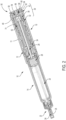
- FIGS. 1-4 An exemplary medication delivery device 10 is illustrated in FIGS. 1-4 as a pen injector configured to inject a medication into a patient through a needle.
- Pen injector 10 includes a body 11 comprising an elongated, pen-shaped housing 12 including a distal portion 14 and a proximal portion 16. Distal portion 14 is received within a pen cap 18.
- distal portion 14 contains the reservoir or cartridge 20 configured to hold the medicinal fluid of medication to be dispensed through its distal outlet end during a dispensing operation.
- the outlet end of distal portion 14 is equipped with a removable needle assembly 22 including an injection needle 24 enclosed by a removable cover 25.
- a piston 26 is positioned in reservoir 20.
- An injecting mechanism positioned in proximal portion 16 is operative to advance piston 26 toward the outlet of reservoir 20 during the dose dispensing operation to force the contained medicine through the needled end.
- the injecting mechanism includes a drive member 28, illustratively in the form of a screw, axially moveable relative to housing 12 to advance piston 26 through reservoir 20.
- a dose setting member 30 is coupled to housing 12 for setting a dose amount to be dispensed by device 10.
- dose setting member 30 is in the form of a screw element operative to spiral (i.e., simultaneously move axially and rotationally) relative to housing 12 during dose setting and dose dispensing.
- FIGS. 1 and 2 illustrate the dose setting member 30 fully screwed into housing 12 at its home or zero dose position.
- Dose setting member 30 is operative to screw out in a proximal direction from housing 12 until it reaches a fully extended position corresponding to a maximum dose deliverable by device 10 in a single injection.
- dose setting member 30 includes a cylindrical dose dial member 32 having a helically threaded outer surface that engages a corresponding threaded inner surface of housing 12 to allow dose setting member 30 to spiral relative to housing 12.
- Dose dial member 32 further includes a helically threaded inner surface that engages a threaded outer surface of sleeve 34 ( FIG. 2 ) of device 10.
- the outer surface of dial member 32 includes dose indicator markings, such as numbers that are visible through a dosage window 36 to indicate to the user the set dose amount.
- Dose setting member 30 further includes a tubular flange 38 that is coupled in the open proximal end of dial member 32 and is axially and rotationally locked to dial member 32 by detents 40 received within openings 41 in dial member 32.
- Dose setting member 30 may further include a collar or skirt 42 positioned around the outer periphery of dial member 32 at its proximal end. Skirt 42 is axially and rotationally locked to dial member 32 by tabs 44 received in slots 46. Further embodiments described later shown examples of the device without a skirt.
- Dose setting member 30 therefore may be considered to comprise any or all of dose dial member 32, flange 38, and skirt 42, as they are all rotationally and axially fixed together.
- Dose dial member 32 is directly involved in setting the dose and driving delivery of the medication.
- Flange 38 is attached to dose dial member 32 and, as described later, cooperates with a clutch to selectively couple dial member 32 with a dose button 56.
- Skirt 42 provides a surface external of body 11 to enable a user to rotate the dial member 32 for setting a dose.
- Skirt 42 illustratively includes a plurality of surface features 48 and an annular ridge 49 formed on the outer surface of skirt 42.
- Surface features 48 are illustratively longitudinally extending ribs and grooves that are circumferentially spaced around the outer surface of skirt 42 and facilitate a user's grasping and rotating the skirt.
- skirt 42 is removed or is integral with dial member 32, and a user may grasp and rotate dose button 56 and/or dose dial member 32 for dose setting.
- a user may grasp and rotate the radial exterior surface of one-piece dose button 56, which also includes a plurality of surface features, for dose setting.
- Delivery device 10 includes an actuator 50 having a clutch 52 which is received within dial member 32.
- Clutch 52 includes an axially extending stem 54 at its proximal end.
- Actuator 50 further includes dose button 56 positioned proximally of skirt 42 of dose setting member 30.
- dose setting member 30 may include a one-piece dose button without the skirt, such as, for example, shown in FIGS. 14 , 18 , 19 , and 22 .
- Dose button 56 includes a mounting collar 58 ( FIG. 2 ) centrally located on the distal surface of dose button 56.
- Collar 58 is attached to stem 54 of clutch 52, such as with an interference fit or an ultrasonic weld, so as to axially and rotatably fix together dose button 56 and clutch 52.
- Dose button 56 includes a disk-shaped proximal end surface or face 60 and an annular wall portion 62 extending distally and spaced radially inwardly of the outer peripheral edge of face 60 to form an annular lip 64 there between.
- Proximal face 60 of dose button 56 serves as a push surface against which a force can be applied manually, i.e., directly by the user to push actuator 50 in a distal direction.
- Dose button 56 illustratively includes a recessed portion 66 centrally located on proximal face 60, although proximal face 60 alternatively may be a flat surface.
- the alternative one-piece dose button such as shown in FIG.
- a bias member 68 illustratively a spring, is disposed between the distal surface 70 of button 56 and a proximal surface 72 of tubular flange 38 to urge actuator 50 and dose setting member 30 axially away from each other.
- Dose button 56 is depressible by a user to initiate the dose dispensing operation.
- Delivery device 10 is operable in both a dose setting mode and a dose dispensing mode.
- dose setting member 30 is dialed (rotated) relative to housing 12 to set a desired dose to be delivered by device 10. Dialing in the proximal direction serves to increase the set dose, and dialing in the distal direction serves to decrease the set dose.
- Dose setting member 30 is adjustable in rotational increments (e.g., clicks) corresponding to the minimum incremental increase or decrease of the set dose during the dose setting operation. For example, one increment or "click" may equal one-half or one unit of medication.
- the set dose amount is visible to the user via the dial indicator markings shown through dosage window 36. Actuator 50, including dose button 56 and clutch 52, move axially and rotationally with dose setting member 30 during the dialing in the dose setting mode.
- Dose dial member 32, flange 38 and skirt 42 are all fixed rotationally to one another, and rotate and extend proximally of the medication delivery device 10 during dose setting, due to the threaded connection of dose dial member 32 with housing 12.
- dose button 56 is rotationally fixed relative to skirt 42 by complementary splines 74 of flange 38 and clutch 52 ( FIG. 2 ), which are urged together by bias member 68.
- skirt 42 and dose button 56 move relative to housing 12 in a spiral manner from a "start" position to an “end” position. This rotation relative to the housing is in proportion to the amount of dose set by operation of the medication delivery device 10.
- device 10 is manipulated so the injection needle 24 properly penetrates, for example, a user's skin.
- the dose dispensing mode of operation is initiated in response to an axial distal force applied to the proximal face 60 of dose button 56.
- the axial force is applied by the user directly to dose button 56. This causes axial movement of actuator 50 in the distal direction relative to housing 12.
- the axial shifting motion of actuator 50 compresses biasing member 68 and reduces or closes the gap between dose button 56 and tubular flange 38. This relative axial movement separates the complementary splines 74 on clutch 52 and flange 38, and thereby disengages actuator 50, e.g., dose button 56, from being rotationally fixed to dose setting member 30.
- dose setting member 30 is rotationally uncoupled from actuator 50 to allow back-driving rotation of dose setting member 30 relative to actuator 50 and housing 12.
- the dose dispensing mode of operation may also be initiated by activating a separate switch or trigger mechanism.
- dial member 32 screws back into housing 12 as it spins relative to dose button 56.
- the dose markings that indicate the amount still remaining to be injected are visible through window 36.
- drive member 28 is advanced distally to push piston 26 through reservoir 20 and expel medication through needle 24 ( FIG. 2 ).
- the amount of medicine expelled from the medication delivery device is proportional to the amount of rotational movement of the dose setting member 30 relative to actuator 50 as the dial member 32 screws back into housing 12.
- the injection is completed when the internal threading of dial member 32 has reached the distal end of the corresponding outer threading of sleeve 34 ( FIG. 2 ).
- Device 10 is then once again arranged in a ready state or zero dose position as shown in FIGS. 2 and 3 .
- the start and end angular positions of dose dial member 32, and therefore of the rotationally fixed flange 38 and skirt 42, relative to dose button 56 provide an "absolute" change in angular positions during dose delivery. Determining whether the relative rotation was in excess of 360° is determined in a number of ways. By way of example, total rotation may be determined by also taking into account the incremental movements of the dose setting member 30 which may be measured in any number of ways by a sensing system.
- an exemplary delivery device 10 may be found in U.S. Patent No. 7,291,132 , entitled Medication Dispensing Apparatus with Triple Screw Threads for Mechanical Advantage.
- Another example of the delivery device is an auto-injector device that may be found in U.S. Patent No. 8,734,394 , entitled "Automatic Injection Device With Delay Mechanism Including Dual Functioning Biasing Member,” where such device being modified with one or more various sensor systems described herein to determine an amount of medication delivered from the medication delivery device based on the sensing of relative rotation within the medication delivery device.
- the dose detection systems described herein use a sensing component and a sensed component attached to members of the medication delivery device.
- the term "attached” encompasses any manner of securing the position of a component to another component or to a member of the medication delivery device such that they are operable as described herein.
- a sensing component may be attached to a member of the medication delivery device by being directly positioned on, received within, integral with, or otherwise connected to, the member. Connections may include, for example, connections formed by frictional engagement, splines, a snap or press fit, sonic welding or adhesive.
- a "directly attached” is used to describe an attachment in which two components, or a component and a member, are physically secured together with no intermediate member, other than attachment components.
- An attachment component may comprise a fastener, adapter or other part of a fastening system, such as a compressible membrane interposed between the two components to facilitate the attachment.
- a "direct attachment” is distinguished from a connection where the components/members are coupled by one or more intermediate functional members, such as the way dial member 32 is coupled in FIG. 2 to the dose button 56 by a clutch 52.
- a first member is “fixed rotationally” with a second member if the two members are required to move together in rotation.
- a member may be "fixed” relative to another member functionally, rather than structurally. For example, a member may be pressed against another member such that the frictional engagement between the two members fixes them together rotationally, while the two members may not be fixed together absent the pressing of the first member.
- the sensor systems comprise a sensing component and a sensed component.
- sensing component refers to any component which is able to detect the relative position of the sensed component.
- the sensing component includes a sensing element, or “sensor”, along with associated electrical components to operate the sensing element.
- sensor is any component for which the sensing component is able to detect the position and/or movement of the sensed component relative to the sensing component.
- the sensed component rotates relative to the sensing component, which is able to detect the angular position and/or the rotational movement of the sensed component.
- the sensing component detects the relative angular position of the sensed component.
- the sensing component may comprise one or more sensing elements, and the sensed component may comprise one or more sensed elements.
- the sensor system is able to detect the position or movement of the sensed component(s) and to provide outputs representative of the position(s) or movement(s) of the sensed component(s).
- a sensor system typically detects a characteristic of a sensed parameter which varies in relationship to the position of the one or more sensed elements within a sensed area.
- the sensed elements extend into or otherwise influence the sensed area in a manner that directly or indirectly affects the characteristic of the sensed parameter.
- the relative positions of the sensor and the sensed element affect the characteristics of the sensed parameter, allowing a microcontroller unit (MCU) of the sensor system to determine different rotational positions of the sensed element.
- MCU microcontroller unit
- Suitable sensor systems may include the combination of an active component and a passive component. With the sensing component operating as the active component, it is not necessary to have both components connected with other system elements such as a power supply or MCU.
- sensing technologies may be incorporated by which the relative positions of two members can be detected.
- Such technologies may include, for example, technologies based on tactile, optical, inductive or electrical measurements.
- Such technologies may include the measurement of a sensed parameter associated with a field, such as a magnetic field.
- a magnetic sensor senses the change in a sensed magnetic field as a magnetic component is moved relative to the sensor.
- a sensor system may sense characteristics of and/or changes to a magnetic field as an object is positioned within and/or moved through the magnetic field. The alterations of the field change the characteristic of the sensed parameter in relation to the position of the sensed element in the sensed area.
- the sensed parameter may be a capacitance, conductance, resistance, impedance, voltage, inductance, etc.
- a magneto-resistive type sensor detects the distortion of an applied magnetic field which results in a characteristic change in the resistance of an element of the sensor.
- Hall effect sensors detect changes in voltage resulting from distortions of an applied magnetic field.
- the sensor system detects relative positions or movements of the sensed elements, and therefore of the associated members of the medication delivery device.
- the sensor system produces outputs representative of the position(s) or the amount of movement of the sensed component.
- the sensor system may be operable to generate outputs by which the rotation of the dose setting member during dose delivery can be determined.
- MCU is operably connected to each sensor to receive the outputs. In one aspect, MCU is configured to determine from the outputs the amount of dose delivered by operation of the medication delivery device.
- the dose delivery detection system involves detecting relative rotational movement between two members. With the extent of rotation having a known relationship to the amount of a delivered dose, the sensor system operates to detect the amount of angular movement from the start of a dose injection to the end of the dose injection. For example, a typical relationship for a pen injector is that an angular displacement of a dose setting member of 18° is the equivalent of one unit of dose, although other angular relationships are also suitable.
- the sensor system is operable to determine the total angular displacement of a dose setting member during dose delivery. Thus, if the angular displacement is 90°, then 5 units of dose have been delivered.
- a sensor system may use a repeating pattern of sensed elements, such that each repetition is an indication of a predetermined degree of angular rotation. Conveniently, the pattern may be established such that each repetition corresponds to the minimum increment of dose that can be set with the medication delivery device.
- An alternative approach is to detect the start and stop positions of the relatively moving member, and to determine the amount of delivered dose as the difference between those positions. In this approach, it may be a part of the determination that the sensor system detects the number of full rotations of the dose setting member. Various methods for this are well within the ordinary skill in the art, and may include "counting" the number of increments to assess the number of full rotations.
- the sensor system components may be permanently or removably attached to the medication delivery device.
- as least some of the dose detection system components are provided in the form of a module that is removably attached to the medication delivery device. This has the advantage of making these sensor components available for use on more than one pen injector.
- a sensing component is mounted to the actuator and a sensed component is attached to the dose setting member.
- the sensed component may also comprise the dose setting member or any portion thereof.
- the sensor system detects during dose delivery the relative rotation of the sensed component, and therefore of the dose setting member, from which is determined the amount of a dose delivered by the medication delivery device.
- a rotation sensor is attached, and rotationally fixed, to the actuator. The actuator does not rotate relative to the body of the medication delivery device during dose delivery.
- a sensed component is attached, and rotationally fixed, to the dose setting member, which rotates relative to the actuator and the device body during dose delivery.
- the sensed component may also comprise the dose setting member or any portion thereof.
- the rotation sensor is not attached directly to the relatively rotating dose setting member during dose delivery.
- a dose delivery detection system 80 including one example of a module 82 useful in combination with a medication delivery device, such as device 10.
- Module 82 carries a sensor system, shown generally at 84, including a rotation sensor 86 and other associated components such as a processor, memory, battery, etc.
- Module 82 is provided as a separate component which may be removably attached to the actuator.
- Dose detection module 82 includes a body 88 attached to dose button 56.
- Body 88 illustratively includes a cylindrical side wall 90 and a top wall 92, spanning over and sealing side wall 90.
- upper side wall 90 is diagrammatically shown having inwardly-extending tabs 94 attaching module 82 to dose button 56.
- Dose detection module 82 may alternatively be attached to dose button 56 via any suitable fastening means, such as a snap or press fit, threaded interface, etc., provided that in one aspect module 82 may be removed from a first medication delivery device and thereafter attached to a second medication delivery device.
- the attachment may be at any location on dose button 56, provided that dose button 56 is able to move any required amount axially relative to dose setting member 30, as discussed herein. Examples of alternative attachment elements for module 82 are shown in FIGS. 15 , 23 and 37 described later.
- dose setting member 30 is free to rotate relative to dose button 56 and module 82.
- module 82 is rotationally fixed with dose button 56 and does not rotate during dose delivery. This may be provided structurally, such as with tabs 94 of FIG. 5 , or by having mutually-facing splines or other surface features on the module body 88 and dose button 56 engage upon axial movement of module 82 relative to dose button 56.
- the distal pressing of the module provides a sufficient frictional engagement between module 82 and dose button 56 as to functionally cause the module 82 and dose button 56 to remain rotationally fixed together during dose delivery.
- Top wall 92 is spaced apart from face 60 of dose button 56 and thereby provides a cavity 96 in which some or all of the rotation sensor and other components may be contained. Cavity 96 may be open at the bottom, or may be enclosed, such as by a bottom wall 98. Bottom wall 98 may be positioned in order to bear directly against face 60 of dose button 56. Alternatively, bottom wall 98 if present may be spaced apart from dose button 56 and other contacts between module 82 and dose button 56 may be used such that an axial force applied to module 82 is transferred to dose button 56. In another embodiment, module 82 may be rotationally fixed to the one-piece dose button configuration, such as shown in FIG. 22 .
- module 82 during dose setting is instead attached to dose setting member 30.
- side wall 90 may include a lower wall portion 100 having inward projections 102 that engage with skirt 42 in a position underneath ridge 49.
- tabs 94 may be eliminated and module 82 effectively engages the proximal face 60 of dose button 56 and the distal side of annular ridge 49.
- lower wall portion 100 may be provided with surface features which engage with the surface features of skirt 42 to rotationally fix module 82 with skirt 42. Rotational forces applied to housing 82 during dose setting are thereby transferred to skirt 42 by virtue of the coupling of lower wall portion 100 with skirt 42.
- Module 82 is disengaged rotationally from skirt 42 in order to proceed with dose delivery.
- the coupling of lower wall portion 100 with skirt 42 is configured to disconnect upon distal axial movement of module 82 relative to skirt 42, thereby allowing skirt 42 to rotate relative to module 82 during dose delivery.
- module 82 may be coupled with both dose button 56 and skirt 42 during dose setting. This has the advantage of providing additional coupling surfaces during rotation of the module in dose setting. The coupling of the module 82 to the skirt 42 is then released prior to dose injection, such as by the axial movement of module 82 relative to skirt 42 as dose delivery is being initiated, thereby allowing dose setting member 30 to rotate relative to module 82 during dose delivery.
- rotation sensor 86 is coupled to side wall 90 for detecting a sensed component.
- Lower wall portion 100 also serves to reduce the likelihood that a user's hand inadvertently applies drag to dose setting member 30 as it rotates relative to module 82 and housing 12 during dose delivery. Further, since dose button 56 is rotationally fixed to dose setting member 30 during dose setting, the side wall 90, including lower wall portion 100, provide a single, continuous surface which may be readily grasped and manipulated by the user during dose setting.
- dose button 56 and dose setting member 30 are rotationally fixed together. Movement of module 82, and therefore dose button 56, a short distance, for example less than 2 mm, releases the rotational engagement and the dose setting member 30 rotates relative to module 82 as the dose is delivered. Whether by use of a finger pad or other triggering mechanism, the dose detection system is activated before the dose button 56 has moved a sufficient distance to disengage the rotational locking of the dose button 56 and the dose setting member 30.
- the dose delivery detection system includes an electronics assembly suitable for operation of the sensor system as described herein.
- Electronics assembly is operably connected to the sensor system to receive outputs from one or more rotational sensors.
- Electronics assembly may include conventional components such as a processor, power supply, memory, microcontrollers, etc. contained for example in cavity 96 defined by module body 88.
- at least some components may be provided separately, such as by means of an external device such as a computer, smart phone or other device.
- Means are then provided to operably connect the external controller components with the sensor system at appropriate times, such as by a wired or wireless connection.
- An exemplary electronics assembly 120 comprises a flexible printed circuit board (FPCB) having a plurality of electronic components.
- the electronics assembly comprises a sensor system including one or more rotation sensors 86 operatively communicating with a processor for receiving signals from the sensor representative of the sensed relative rotation.
- the electronics assembly further includes the MCU comprising at least one processing core and internal memory.
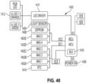
- FIG. 46 One example of an electronics assembly schematic is shown in FIG. 46 .
- the system includes a battery, illustratively a coin cell battery, for powering the components.
- the MCU includes control logic operative to perform the operations described herein, including detecting a dose delivered by medication delivery device 10 based on a detected rotation of the dose setting member relative to the actuator. In one embodiment, the detected rotation is between the skirt 42 and the dose button 56 of a pen injector.
- the MCU is operative to store the detected dose in local memory (e.g., internal flash memory or on-board EEPROM).
- the MCU is further operative to wirelessly transmit and/or receive a signal representative of the detected dose to a paired remote electronic device, such as a user's smartphone, over a Bluetooth low energy (BLE) or other suitable short or long range wireless communication protocol.
- BLE Bluetooth low energy
- the BLE control logic and MCU are integrated on a same circuit. Further description of the electronics arrangement is described further below.
- the rotation sensor may be positioned in a variety of locations in order to sense the relative movement of the sensed component.
- the rotation sensor may be located within cavity 96, within body 88 but outside of the cavity 96, or in other locations of the body, such as on lower wall portion 100. The only requirement is that the rotation sensor be positioned to effectively detect the rotational movement of the sensed component during dose delivery. In some embodiments, the rotation sensor is integral to the device 10.
- One or more sensed elements are attached to the dose setting member 30.
- the sensed elements are directly attached to skirt 42 of the dose setting member.
- sensed elements may be attached to any one or more of the dose setting components, including the dial member, flange and/or skirt. The only requirement is that the sensed element(s) be positioned to be sensed by the rotation sensor during relative rotational movement during dose delivery.
- the sensed component comprises the dose setting member 30 or any portion thereof.
- FIGS. 6-13 Further illustrative embodiments of a dose delivery detection system 80 are provided in FIGS. 6-13 .
- the embodiments are shown in somewhat diagrammatic fashion, as common details have already been provided with respect to FIGS. 1-5 .
- each embodiment includes similar components of the dose detection module 82, including a body 88 having a cylindrical upper wall 90 and a top wall 92.
- Each embodiment also includes a lower wall 100, although it will be appreciated that variations on these components, including the absence of lower wall 100, are within the scope of the disclosure.
- Other parts common to the earlier descriptions herein include an electronics assembly 120 contained within cavity 96 of module body 88, dose button 56, dose setting member 32 and device housing 12.
- dose detection module 82 is diagrammatically shown as being attached to the annular side wall 62 of dose button 56, although alternative forms and locations of attachment may be used.
- dose detection module 82 may be attached to dose button 56 and releasably attached to skirt 42 in some embodiments.
- dose detection module 82 may be attached to one-piece dose button, such as shown in FIGS. 22 and 35 .
- the dose detection system includes multiple sensing systems using the same or different sensing technologies. This provides redundancy in the event of failure of one of the sensing systems. It also provides the ability to use a second sensing system to periodically verify that the first sensing system is performing appropriately.
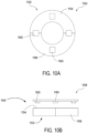
- finger pad 110 attached to top wall 92 of module 82 is a finger pad 110.
- Finger pad 110 is coupled to top wall 92, which is in turn attached to upper side wall 90.
- Finger pad 110 includes a ridge 114 which extends radially inward and is received within circumferential groove 116 of wall component 92. Groove 116 allows a slight axial movement between finger pad 110 and wall component 92.
- Springs normally urge finger pad 110 upwardly away from wall component 92.
- Finger pad 110 may be rotationally fixed to wall component 92. Axial movement of finger pad 110 in the distal direction toward module body 88 as the injection process is initiated may be used to trigger selected events.
- finger pad 110 may be the activation of the medication delivery device electronics upon initial pressing and axial movement of the finger pad 110 relative to the module body 88 when dose injection is initiated. For example, this initial axial movement may be used to "wake up" the device, and particularly the components associated with the dose detection system.
- module 82 includes a display for indication of information to a user. Such a display may be integrated with finger pad 110.
- MCU may include a display drive software module and control logic operative to receive and processed sensed data and to display information on said display , such as, for example, dose setting, dosed dispensed, status of injection, completion of injection, date and/or time, or time to next injection.
- the system electronics may be activated in various other ways.
- the initial axial movement of module 82 at the start of dose delivery may be directly detected, such as by the closing of contacts or the physical engagement of a switch.
- a medication delivery device based on various other actions, e.g., removal of the pen cap, detection of pen movement using an accelerometer, or the setting of the dose.
- the dose detection system is activated prior to the start of dose delivery.
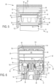
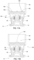
- dose detection module 82 operates using a magnetic sensing system 84.
- Two magnetic sensors 130 are positioned on lower wall portion 100 (illustratively the inside surface of lower wall portion 100) opposite skirt 42 of dose setting member 30.
- the number and location of the rotation sensor(s) and the sensed element(s) may be varied.
- the embodiment of FIGS. 6-8 may instead include any number of magnetic sensors 130 evenly or unevenly spaced around skirt 42.
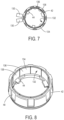
- the sensed component 132 ( FIGS. 7 and 8 ) comprises a magnetic strip 134 secured to skirt 42, illustratively on the interior of skirt 42.
- the strip comprises 5 pairs of north-south magnetic components, e.g., 136 and 138, each magnetic portion therefore extending for 36°.
- the magnetic sensors 130 are positioned at a separation of 18° ( FIG. 7 ), and read the digital positions of magnetic strip 132, and therefore of skirt 42, in a 2-bit grey code fashion. For example, as the sensor detects the passage of an N-S magnetic pair, it is detected that skirt 42 has rotated 36°, corresponding to 2 units, for example, of dose being added (or subtracted).
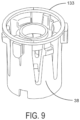
- a sensed component 133 is attached to or integral with flange 38 of dose setting member 30, as illustrated in FIG. 9 .
- the sensing system 84 is configured to detect the amount of rotation of the sensed element relative to the magnetic sensors 130. This amount of rotation is directly correlated to the amount of dose delivered by the device. The relative rotation is determined by detecting the movements of the skirt 42 during dose delivery, for example, by identifying the difference between the start and stop positions of skirt 42, or by "counting" the number of incremental movements of skirt 42 during the delivery of medication.
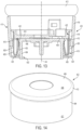
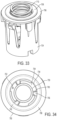
- an exemplary magnetic sensor system 150 including as the sensed element an annular, ringshaped, bipolar magnet 152 having a north pole 154 and a south pole 156. Magnets described herein may also be referred to as diametrically magnetized ring. Magnet 152 is attached to flange 38 and therefore rotates with the flange during dose delivery. In one example, the magnet 152 is attached to the flange 38 with an attachment carrier as shown in FIGS. 31-33 . Magnet 152 may alternately be attached to dose dial 32 or other members rotationally fixed with the dose setting member. Magnet 152 may configured from a variety materials, such as, rare-earth magnets, for example, neodymium, and others a described later.
- Sensor system 150 further includes a measurement sensor 158 including one or more sensing elements 160 operatively connected with sensor electronics (not shown) contained within module 82.
- the sensing elements 160 of sensor 158 are shown in FIG. 11A attached to printed circuit board 162 which is turn attached module 82, which is rotationally fixed to dose button 56. Consequently, magnet 152 rotates relative to sensing elements 160 during dose delivery.
- Sensing elements 160 are operable to detect the relative angular position of magnet 152.
- Sensing elements 160 may include inductive sensors, capacitive sensors, or other contactless sensors when the ring 152 is a metallic ring. Magnetic sensor system 150 thereby operates to detect the total rotation of flange 38 relative to dose button 56, and therefore the rotation relative to housing 12 during dose delivery.
- magnetic sensor system 150 including magnet 152 and sensor 158 with sensing elements 160 may be arranged in the modules shown in FIGS. 13 , 25 and 35 .
- magnetic sensor system 150 includes four sensing elements 160 equi-radially spaced within module 82 to define a ring pattern as shown.
- Alternative numbers and positions of the sensing elements may be used.
- FIG. 11B a single sensing element 160 is used.
- sensing element 160 in FIG. 11B is shown centered within module 82, although other locations may also be used.
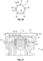
- FIG. 33 and FIG. 40 for example, five sensing elements 906 equi-circumferentially and equi-radially spaced within the module.
- sensing elements 160 are shown attached within module 82.
- sensing elements 160 may be attached to any portion of a component rotationally fixed to dose button 56 such that the component does not rotate relative to housing 12 during dose delivery.
- magnet 152 is shown as a single, annular, bipolar magnet attached to flange 38.
- the magnet may comprise multiple poles, such as alternating north and south poles.
- the magnet comprises a number of pole pairs equaling the number of discrete rotational, dose-setting positions of flange 38.
- Magnet 152 may also comprise a number of separate magnet members.
- the magnet component may be attached to any portion of a member rotationally fixed to flange 38 during dose delivery, such as skirt 42 or dose dial member 32.
- the sensor system may be an inductive or capacitive sensor system.
- This kind of sensor system utilizes a sensed element comprising a metal band attached to the flange similar to the attachment of the magnetic ring described herein.
- Sensor system further includes one or more sensing elements, such as the four, five, six or more independent antennas or armatures equi-angularly spaced along the distal wall of the module housing or pen housing. These antennas form antenna pairs located 180 degrees or other degrees apart and provide a ratio-metric measurement of the angular position of metal ring proportional to the dose delivered.
- the metal band ring is shaped such that one or more distinct rotational positions of metal ring relative to the module may be detected.
- Metal band has a shape which generates a varying signal upon rotation of metal ring relative to antennas.
- Antennas are operably connected with electronics assembly such that the antennas function to detect positions of metal ring relative to sensors, and therefore relative to housing 12 of pen 10, during dose delivery.
- Metal band may be a single, cylindrical band attached to the exterior of the flange. However, alternate configurations and locations of the metal band are contemplated.
- the metal band may comprise multiple discrete metal elements.
- the metal band comprises a number of elements equal to the number of discrete rotational, dose-setting positions of flange.
- the metal band in the alternative may be attached to any portion of a component rotationally fixed to flange 38 during dose delivery, such as dial member 32.
- the metal band may comprise a metal element attached to the rotating member on the inside or the outside of the member, or it may be incorporated into such member, as by metallic particles incorporated in the component, or by over-molding the component with the metal band.
- MCU is operable to determine the position of the metal ring with the sensors.
- MCU is operable to determine the start position of magnet 152 by averaging the number of sensing elements 160 (for example, four) at a maximum sampling rate according to standard quadrature differential signals calculation.
- sampling at a targeted frequency is performed by MCU to detect the number of revolutions of magnet 152.
- MCU is operable to determine the final position of magnet 152 by averaging the number of sensing elements 160 (for example, four) at a maximum sampling rate according to standard quadrature differential signals calculation.
- MCU is operable to determine from calculation of the total rotational angle of travel from the determined start position, number of revolutions, and the final position.
- MCU is operable to determine the number of dose steps or units by dividing the total rotational angle of travel by a predetermined number (such as 10, 15, 18, 20, 24) that is correlated with the design of device and medication.
- a removably attached module is particularly adapted to use with a medication delivery device in which the actuator and the dose setting member both include portions external to the medication device housing. These external portions allow for direct attachment of the sensing component to the actuator, such as a dose button, and a sensed component to a dose setting member, such as a dose skirt, flange, or dial member, as described herein.
- a dose button is used to refer more generally to a component of a medication delivery device which includes a portion located outside of the device housing and includes an exposed surface available for the user to use in order to deliver a set dose.
- a dose “skirt” refers more generally to a component of a medication delivery device which is located outside of the device housing and which thereby has an exposed portion available for the user to grasp and turn the component in order to set a dose.
- the dose skirt rotates relative to the dose button during dose delivery.
- the dose skirt may be rotationally fixed to the dose button during dose setting, such that either the dose skirt or dose button may be rotated to set a dose.
- the delivery device may not include a dose skirt, and a user may grasp and rotate the actuator (e.g., dose button) for dose setting.
- the dose detection module may be rotated to thereby rotate the dose setting member of the delivery device to set a dose to be delivered.
- the sensing system of dose detection system 80 may be originally incorporated into a medication delivery device as an integrated system rather than as an add-on module.
- Detection systems may also be employed with the module for identifying a characteristic of the medication to be administered by a pen injector.
- Pen injectors are used with a wide variety of medications, and even with various types of a given medication as already described.
- insulin is available in different forms depending on the intended purpose. Insulin types include rapid-acting, short-acting, intermediate-acting and long-acting.
- the type of the medication refers to which medication is involved, e.g., insulin versus a non-insulin medication, and/or to a concentration of a medication. It is important not to confuse the type of medication as the consequences may have serious implications.
- This medication type detection is useful with a variety of sensor systems which are operable to detect a predetermined angular position of sensed elements relative to an alignment feature. These sensor systems include those previously disclosed herein. It is a further aspect that this medication type determination is readily combined with sensor systems for detecting the amount of a dose delivery. The two systems may operate independently or in concert with one another.
- any of the modules described herein can be removably coupled to any of the dose buttons described herein via an attachment element 419 coupled to module housing 411.
- Attachment element 419 includes a plurality of distally extending arms 420. As shown generally in FIG. 13 , module 400 is attached to dose button 402 by arms 420 which are attached to and extend distally from housing 411. In an exemplary embodiment arms 420 are equi-radially spaced around dose button 402. Arms 420 are depicted as being attached to distal wall 414 at attachment location 422. Alternatively, arms 420 may be attached to module 400 at other locations, such as at sidewall 416.
- Sidewall 416 may include a distal portion 424 disposed radially outward from arms 420 which extends distally from sidewall 416 a distance farther than the distalmost extension of arms 420 to at least partially or fully cover arms 420 to inhibit tampering or access to arms when mounted to device.
- Distal portion 424 may include an inwardly-extending portion 426 which further encloses arms 420.
- distal portion 424 may be provided as a member which is slidable relative to sidewall 416.
- Arms 420 are configured to move over lip 410 of dose button 402 and to provide frictional engagement with a radially outward facing surface 421 of sidewall 404.
- Arms 420 include a first portion 428 extending axially and configured to extend beyond lip 410.
- Arms 420 further include a bearing portion 430 extending radially-inward of first portion 428 and received against radially outward facing sidewall 404 of dose button 402.
- Portions 428, 430 may be joined by a rounded base 429 coupled between them to form a "J" shape with the first portion 428 forming the staff portion and the base and bearing forming the hook end.
- Bearing portion 430 may include an axially-bearing portion 432 received against the underside of lip 410.
- each of arms 420 is radially movable to clear the lip 410 during attachment to and detachment from dose button.
- both portions 428, 430 flex outward, and in some examples, only one of the first portion 428 or bearing portion 430 flexes outward to move over lip.
- Arms 420 may be biased in a radially inward configuration and may be deflected or pivoted outward about attachment location 422.
- arms 420 are adapted and sized to apply radial normal force against a number of engagement spots along the surface of sidewall 404 that is suitable for axial retention to dose button 402, as well as torque transmission (without or little acceptable slip) during dose setting and/or dose dispensing.
- FIG. 15 An assembly 434 including arms 420 attached to distal wall 414 (shown as molded or manufactured component) is shown in FIG. 15 .
- arms 420 and other components are combined with distal wall 414 (shown as a radially outward surface of wall 414), which is then attached to other parts of module 400.
- FIGS. 16-17 shows the distal wall 414 and some of its component parts.
- Distal wall 414 includes an aperture 436 formed therein to allow an identification sensor, described hereafter, to view the upper surface 408 of dose button 402.
- Light guide aperture 436 may have a variety of shapes, including the "D" shape as shown.
- Another opening 438 formed therein accommodates a presence switch, also described hereafter, to enable module 400 to determine when it is mounted upon dose button 402.
- the number of arms 420 may vary, such as, for example, in the range of 3 to 36, due to desired axial retention force and/or torque transmission.
- Arms 420 are depicted as being attached to distal wall 414 at attachment location 422 defines by posts, which may be a single post or a pair of posts 442, 444 as shown.
- Assembly 434 is shown including sixteen arms 420.
- Assembly 434 is shown including four pairs of mounting posts 442, 444 that are circumferentially spaced around the perimeter of distal wall 414.
- Each pair of mounting posts is configured to support a circumferential segment 445 having a plurality of arms, such as four arms each.
- Each segment 445 includes mounting holes 446 which receive the mounting posts 442, 444. Once received in position, the mounting posts 442, 444 are used to heat stake the arm segments to distal wall 414 in a securely fixed manner.
- the attachment of the arms 420 to the housing allows for fabrication of the arms from a variety of materials. These materials may be selected to obtain desired features of strength, elasticity, durability and the like. For example, it has been found that beryllium copper has advantageous properties for use as the arms.
- the separate attachment also provides flexibility as to the placement of the arms relative to the dose button.
- the arms may be mounted to various walls of the module, including distal wall 414, sidewall 416, or distal portion 424.
- Arms 420 may be suitable for different configurations of surface 421 of dose button 402.
- FIG. 14 illustrates the surface 421 have a smooth (without ribs or grooves or planar variations).
- the surface 421 of button may include surface features to enhance torque transmission with arms 420.
- Other embodiments may be used for the interaction between the arms and the perimetric wall of the dose button.
- FIG. 18 shows another example of a dose button 470 for a device including a sidewall 472 having spaced, axially-extending ridges 474, forming a series of recesses 476 therebetween.
- portions of arms 420 can be receivable within recesses 476.
- Arms 420 may be suitable for another configuration of ridges shown in FIG. 22 .
- the circumferential width of recesses 476 may be sized to receive the circumferential width of arms 420.
- the sizing may allow for a snug fit or may allow some circumferential freedom of arm movement.
- the presence of the adjoining ridges provides further assurance that the module will not rotate relative to the dose button during use.
- FIG. 19 shows an alternate design in which dose button 480 includes a sidewall 482 provided in a polygonal shape, thereby defining a series of flat surfaces 484 for reception of the arms of the module. Separating adjacent flat surfaces 484 is a rounded axial joint 485.
- the use of a flat, smooth cylindrical surface avoids any issues regarding orientation of the module relative to the dose button, while the recessed and polygonal designs provide additional frictional engagement of the arms with the sidewall of the dose button.
- FIGS. 20-24 illustrate another example of a module attachment subassembly, now referenced as unit 500, configured, when part of a module, to be removably coupled to any of the dose buttons described herein via an attachment element 519.
- Attachment element 519 is coupled to a tubular attachment housing 511 (although other parts of the module housing are omitted, aspects of these parts to define a full module housing are shown in FIG. 13 and FIG. 25 ).
- Attachment housing 511 with the attachment element 519 may form a part of the module 600 as will be described later.
- Attachment element 519 includes a plurality of distally extending arms 520. As shown generally in FIG.
- unit 500 when part of a module is attached to another example of dose button 502 by arms 520 which are attached to and extend distally from housing 511, and in particular distally from annular housing portion 517 of housing 511 at recessed areas defined by the distal wall 514.
- the annular housing defines a cavity to receive for example at least partially electronics.
- arms 520 are equi-radially spaced around dose button 502. Arms 520 are depicted as being coupled to and depending from a distal wall 514 of attachment housing 511.
- Protruding body 531 of bearing portion 530 may include a distal facing end 537.
- the surface 532 and/or distal facing end 537 may be angled at any angle to give the protruding body 531 a tapered profile.
- Protruding body 531 may include a radially facing engagement surface 538 having an axial length extending between surface 532 and end 537. Engagement surface 538 may by planar, rounded (as shown), tapered or V-shaped.
- protruding body 531 may have a smaller width than the width of the arm 520.
- the arms may include more than one protruding body arranged to fit within adjacent ridges or alternating ridges.
- FIG. 22 depicts the sidewall 504 of dose button 502 includes a plurality of spaced, axially-extending ridges 545, forming a series of recesses 547 therebetween.
- Button 502 also includes a proximal wall with a proximal upper surface 508. At least a portion of the proximal surface 508 may have a color to correspond to a unique kind of medication and/or dosage.
- the button 502 with color is representative of all the other buttons described herein as those other buttons may have similar color schemes.
- any of the modules described herein can be attached to different kinds of pens, and with the use of color detection the module can communicate the identification information to an external device.
- the module and/or external device may determine a different number of units of medication delivered for the same amount of total rotation due to the pen having a unique rotational profile for a given medication and dosage.
- the entire upper surface 508 of the button 502 is a single color.
- a surface feature or region 507A such as recess or a protrusion or the center of the button surface, may have a first color
- a region 507B adjacent to the surface feature or specific region may have a second color different than the first color.
- the medication identification sensing described herein may be directed to the first color or the second color depending the module's configuration.
- at least a portion of the bearing portion 530 of arms 520 are receivable within recesses 547.
- each of the recesses 547 may be sized to receive the circumferential width of engagement surface 538 of bearing portion 530, and in other embodiments, recesses 547 may be sized to receive a tip end portion of the engagement surface of any of the tips of the arms described herein, such, as, for example, as shown in FIG. 20 .
- the circumferential width of each bearing portion 530 may be oversized to fit over the recesses 547, engaging adjacent ridges without going into the recesses.
- the proximal extent 549 of the recesses 547 may extend within the radial lip 510. The depth D1 of the recesses 547, shown in FIG.
- the depth of the recesses 547 may vary along the axial extent, such as, for example being sized to be deeper toward the proximal end than toward the distal end of recess 547.
- Arms 520 may also suitable for other button surfaces, such as, for example, shown in FIGS. 14 , 18, and 19 .
- the overhang axial distance O of axially-bearing surface 532 of arms 520 relative to the distally facing axial surface 513 of distal wall 514 may be larger than the axial depth D of the radial lip 502.
- the distal end 513 of the bearing portion 530 that is, the distalmost part of the bearing portion 530 that is in direct engagement with the sidewall 504, of arms 520 engages the surface 521 of sidewall 504 at an axial distance HL, thereby placing the surface engagement portion 538 of bearing portion 530 between the radial lip 510 and the engagement location of distal end 513 against the sidewall.
- the bearing portion may axially extend between the underside of the rim 510 and the engagement location of the distal end 513 that is located along the upper half of the sidewall 504.
- Axial distance HL is measured between said plane defined by the surface 505 that is against the upper surface 508 of dose button 502 and such engagement location of the distal end 513, as shown in FIG. 24 .
- the axial distance HL may be sized up to 50% of the axial height H of the dose button 502 to place the bearing portion 530 along the proximal portion 509 of sidewall 504. This position may reduce the spatial impact of the arms within the attached module placed the button.
- Engagement surface 538 of the bearing portion 530 is sized axially larger than the axial thickness of the radial lip 510 for greater radial force.
- the bearing portion 530 of the arms 520 in a more axially compact configuration as shown may reduce the amount of axial travel and friction causing forces of surface 538 of the bearing portion along the rim 510, and thereby reducing the attachment and/or detachment force for the user.
- a more axially compact bearing portion of the arms may also reduce the amount of duration for attachment and/or detachment of the module so that user is not left doubting whether attachment was successful.
- FIG. 21 illustrates each of arms 520 is radially movable in a direction of arrow 535 to clear the lip 510 during attachment to (or moving module in a proximal direction P relative to the dose button) and detachment from dose button (or moving module in a distal direction DD relative to the dose button).
- Arms 520 may be biased in a radially inward configuration and may be deflected or pivoted outward about where the arms depend from the distal wall 514.
- arms 520 are adapted and sized to apply radial normal force against a number of engagement spots along the surface of sidewall 504 that is suitable for axial retention to dose button 502, as well as torque transmission (without or with little acceptable slip) during dose setting and/or dose dispensing.
- the unit 500 that is coupled to button 502 is rotated in a first direction that moves the module/button farther away from the device housing.
- the attachment force that the user applies in the distal direction DD may be less than the detachment force that the user applies in the proximal direction P.
- the detachment force may be in the range of 4 N to 30 N.
- the arms are configured such that the detachment force is at least 1.5 times the attachment force, and may be at least twice as large as the attachment force to inhibit inadvertent detachment of the module.
- the detachment force is over 20 N and the attachment force is under 11 N.
- a small degree of slippage of the bearing portions along the dose button due to torqueing from dose setting may be permissible in order to avoid over-torqueing and potential damage to the dose setting device components.
- the arms 520 and housing 511 may be formed as an integral unit, such as with molding of a plastic material, such as an acetal thermoplastic (for example, Delrin ® ), or polycarbonate material (for example, Makrolon ® ). Such an integral unit 561 is shown in FIG. 23 .
- the plastic materials may be selected to obtain desired features of strength, elasticity, durability and the like.
- the arms 520 may be separately made from the housing and later attached via an adhesive or welding.
- the number of arms 520 may vary. In the example shown, there are four arms positioned circumferentially spaced equally apart. In some examples, three arms may be provided, in other examples, 5, 6, 7, or 8 arms may be provided.
- the arms described herein provide a convenient and effective attachment of the module to the dose button.
- the module attachment allows for ready attachment and removal of the module relative to the dose button. This derives from the arms described herein having suitable configurations and physical properties to set the amount of force required to attach/detach the module.
- the arms described herein are also configured to have sufficient durability for repeated attachments to medication delivery devices, and to retain elasticity to provide proper securement and retention to the button without the use of a separate retainer piece, such as a coiled spring or ring, disposed along the outside to provide radially compressive force.
- the module is frictionally engaged with the dose button.
- This allows for use of the module to rotate the dose button as desired, such as during dose setting for some medication delivery devices.
- the surface engagement of the bearing portions of the arms described herein may be controlled through various parameters. Frictional engagement depends on such factors as the force applied normal to the module surface and the coefficient of friction applicable for the contacting surfaces. The applied radial force is dependent, inter alia, on the sizes and shapes of the arms, the elasticity and resilience of the arms, and other factors.
- the disclosed attachment elements allow for selection among these and other parameters in order to provide the desired balance to frictionally lock the module with the dose button for rotation, and to allow for ready attachment and detachment of the module relative to the dose button.
- any of the modules described herein may include one or more switches to facilitate use of the module, even though the following description is related to the module 600.
- the module is releasably attached to a medication delivery device. When desired, the module is removed from one medication delivery device and then is useful in conjunction with another medication delivery device.
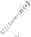
- the module 600 includes a proximal wall assembly 602, sidewall 604 and distal wall 606. Walls 602, 604, 606 of module 600 thereby defines an internal compartment 608 configured to house an electronics assembly 610.
- Wall 602 may include a transparent or translucent material around the upper edge to provide a light guide when LEDs are employed.
- attachment element 607 is illustratively shown as the attachment element 419 in FIG. 15 , it should not be limiting as module 600 can also be provided with any other attachment unit described herein.
- proximal end opening of the tubular attachment housing 511 is sized to fit over the circumferential outer surface 609 of distal wall 606 with a friction fit or otherwise securely fixed.
- distal wall 606 is illustratively shown in FIGS.
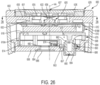
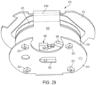
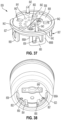
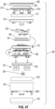
- FIGS. 25 , 26 , 27 and 29 show an example of electronics assembly 610 that may be used for any of the modules described herein.
- Assembly 610 includes a first distal segment 612, a second proximal segment 614, and a third intermediate segment 616 therebetween, each having electronically connected by connections and leads, shown generally at 618A-B.
- Segments 612, 614, 616 may be coupled coaxially disposed over one another in an "S" pattern.
- Battery 621 is shown axially disposed between the first and third segments 612, 616 and captured by resilient arms.
- the second segment 614 may include sensor pockets 623 defined therein for receiving the measurement sensors, such as, for example, sensing elements 160. Pockets 623 are aligned and inserted within recessed locations 440 of distal wall of module housing. Alternatively, instead of pockets 623, the measurement sensors may be coupled directly to the second segment circuit without the pockets.
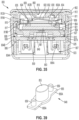
- the first segment 612 includes a proximal facing surface 615 and includes an example of a switch 622 of a wake-up switch system 620 mounted thereon.
- Module may include indicator elements 624, such as LEDs for indication of operator status of device and/or module.
- the indicator elements 624 are operably mounted to surface 615 of first segment 612.
- Activation of wake-up switch 622 may be used to turn on relevant electronics, such as those associated with the delivery of a dose.
- wake-up switch 622 may turn on the measurement sensor, such as, for example, the sensing elements 160, involved in the measurement of a dose delivery generated by rotation of the sensed element.
- LEDs or other indicator elements such as, audible speakers and/or vibration generators, may be used to notify the user of the progression of the system through completion of the dose delivery or notify the user between periods of dose delivery, such as, for example, battery charge indication.
- LEDs are mounted on the sides of the switch 622.
- Wake-up switch system may be configured to increase the power to the electronics from a low power state to a full operation state.
- any of the module described herein may include a wake-up switch system 620.
- the provision of such wake-up switch with a module may be optional.
- the module 600 shown in FIGS. 25-26 includes the wake-up switch system 620 which includes an axially movable segment 626 disposed within a recess defined in the upper surface of the proximal wall assembly 602.
- Wake-up segment 626 is able to move distally into module 600, and has a biased configuration as shown.
- Wake-up segment 626 may for example comprise a flexible disc-shaped member which is normally in a proximal position, or it may be a member that is biased proximally such as by springs (not shown).
- the material of the wake-up segment may allow for some deflection of the center 627 of the segment 626 relative to the circumferential edge 629 of the segment 626.
- Segment 626 may be a rigid member slidably disposed along walls defining a recess within the proximal portion 602 of the module housing.
- Segment 626 may include an anchoring segment (not shown) movably coupled to the module housing such that that when segment 626 is in its biased proximal position, segment remains within module housing without exiting the module.
- Walls 630 of proximal wall assembly 602 may be shaped to define a proximally facing axial surface 631 configured to define a physical stop or its distalmost position for the distal travel of the segment 626 from its biased proximal position.
- Walls 630 define a smaller sized portion of the throughbore 632 extending axially along the axis AA through the proximal wall 602.
- segment 626 When user distally actuates the wake-up segment 626, the axial force is sufficient to overcome the biasing force of the spring (not shown) and allow distal movement of the segment 626 until directly or indirectly causing activation of the switch system 620. This axial force to actuate wake-up is less than the axial force to cause actuation of the delivery device for dose delivery.
- segment 626 may be distally moved to engage the axial surface 631, while the walls 630 defining the throughbore 632 may be sized and shaped to allow continued axial deflection of segment 626 distally beyond the axial surface 630 such that there is sufficient to activate the switch system 620.
- the switch shown includes a mechanical switch or rubber dome switch, while other switches are contemplated such as electrical contacts. Switches described herein can be mechanically actuated or triggered by engagement with another component.
- switch system 620 may further include a flexible shroud 635 configured to limit the travel of distal deflection of segment 626 when pressed by user to inhibit damage to the wake-up switch 620.
- Shroud 635 may be axially located between the segment 626 and the switch 622. Axial force from the user may be transmitted via the segment 626 to shroud 635 to cause central portion 638 of shroud 635 to axially deflect to engage the trigger of the switch 622.
- Shroud 635 may be configured to have a maximum distal extent of deflection. Such distal extent may be sized to allow engagement of the switch trigger but not farther to a position that may damage the switch. Shroud may have various sizes and shapes for such functionality.
- FIG. 28 illustrates one example of shroud 635, including a plurality of radial legs 640 circumferentially disposed relative to one another, extending from a centerpoint of a hub 642 that surrounds central portion 638 of shroud. Centerpoint of hub is located coaxially with the axis AA.
- the hub 642 and central portion 638 may have any shape, and may be rectangular, oval, or circular as shown.
- the central portion 642 may include a concaved region that extends the hub in the distal direction relative to the surrounding hub region radially outside the concaved region.
- the end tips 643 of a first set of legs 640A may be coupled to anchor portions 644, such as for example the distal surface of anchor portions 644 having a slotted region sized and shaped to receive the size and shape of the tips 643.
- Anchor portion 644 extend distally from axially movable segment 626, which place the anchor portions 644 on top of the tips 643.
- Anchor portions 644 moves axially with segment 626 within throughbore 632 when user applies axial force thereto.
- Anchor portions 644 may be integrally formed with the segment 626 such as from molding or portions 644 may be formed separately and fixedly secured to the distal surface of segment 626.
- the tips 646 of a second set of legs 640B may be free or remain unengaged with the segment 626.
- the first set of legs 640A may be contacted by anchor portions 644 at equi-angularly locations to distribute the axial force and deflection to each of the legs 640.
- the first set of legs 640A are shorter in radial length than the longer second set of legs 640B.
- the first set of legs 640A may radially extend directly in between adjacent legs of the second set 640B. While all of the legs 640 may provide flexibility to the shroud 635, the free legs 640B can inhibit the shroud 636 to have the maximum distal extent of deflection while force is axially transmitted from segment 626 to the tips 643 via the anchor portions 644 to move the tips 643 within the throughbore 632.
- the electronic assembly 610 is powered on from a sleep state by axial movement of segment 626 and shroud 635 caused by a user to a degree to contact the axial trigger of switch 622, such as, for example, without any distal movement of the module and/or dose button.
- the wake-up switch may include one or more leaf spring electrical contact elements that are biased away from contact with corresponding contact pads mounted on the first segment, and are movable for contacting the contact pads from force transmission via the member 626.
- power on of electronic assembly occurs by simultaneous contact of each of the contact elements.
- module 600 includes presence switch system 650 mounted to distal wall 606 in a manner to detect when module 600 has been mounted to or removed from a medication delivery device.
- a presences switch 652 of system 650 is operably connected to the proximal face 617 of the second segment 614 of electronics assembly 610.
- Switch 652 includes a pivot switch arm 654 positioned at least partially overlapping the opening 657 (see opening 438 in FIG. 16 ) defined by distal wall 606.
- Distal wall 606 may include the same layout (or substantially the same layout) of features, such as, for example, openings 438, 436 and features 440, 441, shown in FIG. 16-17 .
- Switch arm 654 of switch 652 has a biased position (shown in FIG. 27 ) and a distal position (shown in dashed lines).
- switch system is movable from its biased distal position (as shown in FIG. 26 ) representing the absence of a medication device, to a proximal position (shown in FIG. 25 ) indicating that module 600 is mounted to a medication delivery device.
- Presence switch system 650 includes a switch actuator 660 that is mounted to distal wall 606.
- Actuator 660 includes a first member 662 in a nesting relationship with a second member 664.
- the second member 664 has a cup configuration defining a cylindrical cavity to receive the first member 662.
- the second member 664 is slidably disposed through opening 657.
- the second member 664 includes an outer radial lip 663 along its proximal end and housed within module to enhance the inhibition of particulates and/or water ingress. Though the radial lip 663 is shown in FIG. 25 disposed away from distal wall, the radial lip 663 may remain engaged with the distal wall, such as shown in FIG. 26 , when the module is attached to the device.
- the second member 664 may be made of elastomer or soft plastic material for flexibility. Second member 664 is movable within the module housing to a proximal position by direct engagement with the device when mounting the module to the device. First member 662 is shaped and sized to fit within the cavity defined by the second member 664. First member 662 includes a cylindrical body 666 extending axially between its proximal and distal axial ends. An outer radial rim 668 is shown extending from an intermediate segment of the first member body 666 such that a distal hat segment 670 is defined for insertion into a distal end of an actuator spring 672.
- the actuator spring 672 is fixedly secured at its proximal end to an internal component of the module housing, and the actuator spring's distal end is bearing on the rim 668 and movable therewith.
- Rim 668 may include a distal skirt 674 depending from the distal surface of the rim 668. In one example, the distal skirt 674 is coupled to the outer radial end of the rim.
- the rim 668 may comprise of diametrically disposed radial elements instead of a continuous circumferentially element.
- the first member 662 Under the biasing force of the actuator spring 672, the first member 662 is in a nested position within the second member 664 and the rim 668 of the first member 662 is configured to contact and distally move the switch arm 654 to place the system at its biased distal position when the module is removed from the device.
- Switch system 650 in its distal position indicates electronically the module is not mounted to a device, and power limitations may be programmed into the processor to perform minimal functions.
- Skirt 674 may provide radial pressure along the lip 663 of the second member against the interior surface of distal wall 606 to enhance inhibition of particular ingress.
- the exterior end of the second member 664 with the first member 662 is in a nested position contacts the dose button of the device and force is transmitted to the rim via the body of the first member to overcome the force of spring 672, thereby causing the first and second members to move proximally within the module housing and thereby allowing the switch system to return to the proximal position.
- Switch system 650 in its proximal position indicates electronically the module is mounted to a device, and full power may be programmed into the processor to perform all functions.
- Actuator 660 is biased in the distal direction by spring 672, and normally extends distally out of opening 657 when module 600 is not mounted to a medication delivery device. As shown somewhat diagrammatically in FIG. 25 , mounting module 600 to any one of the dose buttons described herein, generally 601, causes the upper surface of dose button 601 to press actuator 660 proximally, and this movement in turn moves switch arm proximally, triggering presence switch 652. MCU of electronic assembly 610 recognizes the proximal position of switch arm 654 as a confirmation that unit 500 is mounted to a medication delivery device. In response, MCU wakes up or provides power to relevant components of electronics assembly 610 in preparation for use of the medication delivery device.
- spring 672 moves actuator 660 back outside of distal wall 606 and switch arm 654 returns to its distal position identifying that module 600 is not mounted to a medication delivery device. MCU then returns the medication delivery device to a non-use state, such as by turning the module systems off or setting them in a sleep mode.
- electronic assembly 610 is shown schematically in FIG. 46 .
- any of the modules described herein, such as module 600 may also include a sensor for identifying the type of medication delivery device, or the type of medication contained by the medication delivery device.
- the identification sensor 680 is operably connected to the distal face 617 of the third segment 616 of the electronic assembly 610.
- the second segment 614 includes a window opening 682 defined therein.
- Identification sensor 680 is located over window opening 682 and aperture 684 of distal wall 606 (see aperture configuration and layout in aperture 436 in FIGS. 16-17 ) to be able to view the exposed surface of dose button 601.
- a recess 686 may be formed along the distal face of the distal wall 606 that overlaps the aperture 684.
- the recess 686 may receive a coupled lens or shield therein to aid in keeping debris out.
- Dose button 601 is provided with indicia visible to type sensor 680 through aperture 684.
- the indicia correlate to information concerning the medication delivery device, such as the type of device or the medication contained by the device.
- Identification sensor 680 reads the indicia and MCU recognizes the indicia as indicating the medication delivery device information.
- a light guide member 685 may be disposed within the aperture 684 to provide an optical path for the identification sensor. Securing light guide member 685 to distal wall 606, such as, by snap fit or adhesive or ultrasonic welding, can prevent light and sensing distortion caused by relative movement or vibration of the light guide member.
- Light guide member 685 which could be made from a transparent or translucent material, such as, for example, a polycarbonate, is shown extending axially between the upper surface of the button 601 and the opening 682.
- Recess 686 may be also be configured to receive an enlarged base portion of the light guide member 685.
- identification sensor 680 may comprise an RGB source(s) and sensor to detect color reflected from the dose button and the indicia may comprise different colors, each color being associated with specific information regarding the medication delivery device. Shielding elements may be provided to guide RGB light sources axially to button and to inhibit premature reading of light form sensor. Alternatively, the indicia may comprise grey scale, patterns, or other material that is optically recognizable. In addition, more than one type sensor may be employed to enhance the detection of information regarding the medication delivery device. In one embodiment, identification sensor 680, is positioned to detect the near-center or center of the proximal upper surface of dose button 601. The indicia may at the same time comprise patterns symmetrically positioned around the center of dose button 601, such as concentric color rings. With type sensor 680 so located, presence switch 652 is positioned displaced from the center of module 600.
- identification sensor 680 is activated with module 600 mounted to a medication delivery device.
- presence switch 652 detects the mounting of unit 500 on a medication delivery device and identification sensor 680 is activated at that time.
- the sensed information concerning the medication delivery device may be stored and/or transmitted.
- Module 600 may then be moved to a lower power mode, such as after a predetermined time period, until reactivated during dose delivery.
- the distal wall 606 as a component is provided in the orientation and arrangement shown in FIG. 16 .
- the switch actuator 660 with the first and second elements is inserted through opening 657 with the rim 668 of the first element sized to fit within the axial slots formed by upstanding walls surrounding and extending from the edge of opening (as shown in FIG. 16 ).
- Actuator spring 672 is placed on top of the actuator as shown in FIG. 25 .
- the second segment 614 is placed with the interior of the distal wall component in alignment around the various features and openings formed along the distal component.
- An axial spacer component 675 (shown in FIG. 25 ) is placed over top of the second segment 614 and the distal wall.
- Spacer 675 includes alignment features to position the segments at a predetermined relative distance.
- the segments are then folded over along connection 618A in order to place the third segment 616 proximally on top of the spacer 675.
- Battery 621 is disposed on top of the third segment 616 and configured to operably provide power to all of the segments.
- the first segment 612 is then folded over along connection 618B in order to place the first segment 612 proximally on top of the battery 621.
- module 800 includes the proximal wall 802, sidewall 804 and distal wall 806. Walls 802, 804, 806 of module 800 thereby defines an internal compartment 808 configured to house the electronics assembly 810.
- Proximal wall 802 may have a disk shape and form the finger pad that user presses for device operation.
- Module may include a ring 812 of transparent or translucent material around the upper edge to provide a radial light guide when a light source, such as, for example, LEDs, is employed, such as shown in FIG. 27 .
- the distal surface of the proximal wall may include the white or reflective surface.
- the distal surface 862 of the tape 860 includes the white or reflective surface, and in other examples a disk element with a white or reflective surface may be used.
- the proximal wall assembly described herein may only refer to the proximal wall without the light ring.
- Ring 812 may include an attachment element to attach to another module component.
- ring 812 may include a plurality of retention snap arms 812A depending from a distal surface of ring 812. Arms 812A are configured to permit axial movement of the proximal wall relative to the housing and including tips configured to prevent removal of the ring 812 to a certain position.
- FIG. 47 depicts an exploded view of one embodiment of the module, such as module 800, separated into its individual components along a common axis.
- Module may include a first spacer element 815 having a ring shape and defining an inner radial surface 817 disposed along the circumference defined by the snap arms 812A.
- Surface 817 configured to allow controlled axial movement of the proximal wall assembly from the proximal position to the distal position for wake-up capability.
- the distal surface of spacer element 815 along the inner radial surface 817 provides an area for the snap arms 812A to engage for retention as the proximal wall assembly returns to the proximal positon under the biasing force.
- the light ring is omitted and the proximal wall includes the snap arms for engagement with the surface 817.
- Spacer element 815 may include a proximal flange 819A disposed along the radial outward extent of the spacer element.
- the upper end of flange 819A can provide a physical stop to limit distal movement of the proximal wall 802.
- Spacer element 815 may include a distal flange 819B disposed along the radial outward extend of the spacer element and recessed radially inward relative to the proximal flange 819A.
- the recess may be sized to accommodate the thickness of sidewall 804 when the upper end of the sidewall engages the radial outer surface of the distal flange 819B.
- Button gasket 811 is disposed axially between the proximal wall 802 and ring 812 and a housing portion in the form of the spacer element 815.
- the button gasket 811 is engaged between ring 812, or the proximal wall if there is no ring, and element 815.
- Gasket 811 is axially compressible from its natural state.
- the gasket material such as for example, a cellular urethane form, may be configured to provide compressibility.
- the material of gasket 811 may also provide sealing from liquid egress, but allowing the ventilation. In other embodiments, the gasket material may provide sealing from liquid and air egress.
- the gasket 811 may provide a biasing force and support along the outer circumference of the proximal wall assembly to maintain the proximal wall assembly in its extended proximal position.
- the button gasket 811 may axially compress as the ring/proximal wall unit moves distally relative to the spacer element 815 that is in a fixed position.
- the gasket 811 may aid in returning the proximal wall assembly to the extended position and provide consistent tactile feedback to the user throughout its movement.
- a spring with lining or other sealing means may be used.
- Module may include a second spacer element 821 disposed distal to the first spacer element 815 in between the element 815 and distal wall 806.
- Second spacer element 821 has a ring shape.
- the second spacer element 821 is coupled to the first spacer element 815, such as, for example, each having axially extending features that allow for coupling.
- Battery 861 is shown disposed between elements 815, 821.
- a battery retainer element (not shown) can be coupled to the proximal surface of the second space element.
- a battery support element 864 may be included between the proximal side of the battery and one of the circuit boards of the electronics assembly, and in frictional contact with the battery to inhibit movement of the battery within the module.
- the battery support element 864 may include a ring of axially compressible material, such as, closed cell foam.
- the element 864 may have a cross-sectional area less than the battery's cross-sectional area.
- Sidewall 804 is shown disposed radially outward relative to the contents of the module and axially extended between the first spacer element 815 and a base ring 823 that is coupled to the distal end of the sidewall 804.
- Base ring 823 may be optional.
- Sidewall 804 may include a plurality of distally extending retention snap arms 804A for engaging with correspondingly shaped recesses formed along the interior surface of the base ring 823 in a manner to securely fix the components together.
- Distal gasket 825 has a ring shape and is disposed radially between the interior surface of sidewall 804 and the outer circumference of the distal wall 802, and axially between seat 804B and a seat 827A defined by a radial flange 827 extending from the distal wall 802.
- gasket 825 is sealably engaged between sidewall 804 and distal wall 802.
- Gasket 825 may be made from a gasket material, such as for example, a cellular urethane form, may be configured to provide compressibility.
- a presence switch system such as, for example, the system 650 described earlier may be incorporated into the module as can be appreciated by those skilled in the art.
- Module 800 is shown including another embodiment of a wake-up switch system, now referred to as wake-up switch system 820.
- wake-up switch system 820 is illustratively shown, it should not be limiting as module 800 can also be provided with the wake-up switch system 620.
- the other modules described herein may include wake-up switch system 820.
- wake-up switch system 820 includes one or axially moveable contact arms 822 and a corresponding contact pad 824 coupled to the circuit board 809, which can be the flexible printed circuit board (FPCB), of the electronics assembly 810 and in electrical communication with the MCU.
- Contact arm 822 is able to move distally from a biased, non-contact natural configuration, as shown in the figures, where the contact arm 822 is axially spaced from the contact pad 824 such that there is no electrical communication (thus electronics in a low power state) to a contact configuration by which the contact arm 822 and contact pad 824 are in a contacting relationship such that there is electrical communication between the two (thus increasing power to electronics to the full operation state).
- Contact arm 822 may have a pre-load to maintain contact with the proximal wall 802 along different axial positions of the movable proximal wall.
- the biasing may be provided by a discrete spring or the contact arm 822 may have a leaf spring configuration, such as shown.
- the contact arm 822 includes a base 830 fixedly mounted to the circuit board 809, a movable arm length portion 832 coupled to the base 830 via a joint 834.
- the arm length portion 832 is capable of pivoting motion relative to the base 830 about the joint 834.
- the biasing force from the contact arm 822 may be sufficient to maintain the upper proximal wall 802 in a proximal first position.
- the axial force is sufficient to overcome the biasing force of the contact arm 822 and allow for the distal movement of the proximal wall 802 away from its first position to a distal second potion where the contacting arm 822 and contact pad 824 are in contact for activation of the switch system and/or wake-up of the control system.
- Movement of the proximal wall 802 may occur relative to the module housing that is in a fixed position during this action to power-on the system without an actuation force on the actuator. Movement of the proximal wall 802 may also occur relative to the module housing that is in the process of moving to a final distal position during the actuation force on the actuator to cause dose delivery.
- the switch system 820 may include alternative switch configurations, such as, for example, a mechanical switch or rubber dome switch.
- Contact length arm portion 832 may extend from the base 830 at an acute angle relative to a plan defined by the base 830, although the angle of extension of the arm portion may be orthogonal or acute relative to the base. From a radial view perspective, the contact arm may have a V-shaped body. In one example, any part of the arm portion 832 may include a contacting portion contactable with the contact pad 824. In one embodiment shown, the tip end 835 of the arm portion 832 defines the contacting portion. In another embodiment, the contacting portion is along the intermediate body of the arm portion 832.
- the contacting portion of the arm portion 832 may be configured for enhanced contacting the contact pad 824, such as, for example, including a polished or smoothed surface and/or a rounded surface or hook shape and/or a domed surface (such as shown in FIGS. 35-36 ).
- the arm portion 832 may be angled along its body at a bearing joint 837 to define a proximal extending first portion 840A and a distally extending second portion 840B.
- the first portion 840A extends between the base 830 and joint 834 portion and the bearing joint 837.
- the second portion 840B extends between the bearing joint 837 and the tip end 835.
- first portion 840A is configured to place the bearing joint 837 at a location to maintain contact with the interior surface 802A of the proximal wall or the light ring, or alternatively corresponding bosses 802B extending distally from surface 802A, of the proximal upper wall 802 when moving between its first and second positions.
- the length and angle of extension of second portion 840B in the distal direction is configured to place the tip end 835 in a spaced relationship with the contact pad 824 when the proximal wall 802 is at the first position, and to allow distal movement of the tip end 835, together with the proximal wall 802, for a sufficient distance to contact the contact pad 824 when the proximal wall 802 is at the second position.
- the bearing portion 837 of the contact arm 822 may be located in closer proximity to the tip end 835 of the arm portion than the location of the contacting portion.
- the contacting portion may be formed along a valley or recess of the arm portion.
- the bearing portion of the contact arm is disposed in a more proximal location than the contacting portion.
- the configuration of the arm portion 832 of contact arm 822 may be linear, angular, or curved.
- FIG. 36 illustrates an example of the arm portion 832 having an arcuate shape. Although one contact arm and contact pad system may be sufficient for wake-up functionality of a module, FIG. 36 depicts the system including three sets of contact arms 822 and contact pads (not clearly shown in the figure). As shown, the three contact arms 822 may be disposed radially from the longitudinal axis about the same distance. The arms 822 may be disposed circumferentially spaced from one another at equal distance, such as, for example, allowing for 20 to 40 degrees of separation between adjacent ends of the contact arms.
- the controls may be configured to require one only set of contact arm 822 and contact pad 824 or less than all of the total number sets to make contact for activation. Requiring less than the total amount of contacts for activation can allow the user to press any portion of the proximal wall to cause wake-up, rather than requiring the user accurate finger placement.
- the controls may be configured to require more than one set, such as, for example, all three sets, of contact arms 822 and contact pads 824 to make contact for activation.
- the base 830 and contact arm portion 832 may be formed integrally from the same material, such as, an electrically conductive material, such as metal.
- the contact pad 824 is made of material conductive with the contact arm.
- the base and arm portion may be formed separately from same materials or different materials. If formed separately, the base and arm portion may be coupled to one another, such as, for example, welding, metal welding epoxy, brazing, or other means depending on the materials of the components.
- the base and arm portion may be formed from a plastic material having conductive material impregnating the plastic material in at least the tip end portion or having a conductive material coating along the tip end.
- the base and arm portion is formed integrally from an electrically conductive metallic material and are coupled to one another at a living hinge joint such that the contact arm has a leaf spring configuration.
- FIG. 37 shows another example of a module attachment subassembly, now referenced as spacer unit 839.
- Unit 839 is configured, when part of a module, to permit the module 800 to be removably coupled to any of the dose buttons described herein via the attachment element 807.
- Distal wall 806 includes the aperture 836 defined therein for receiving a light guide member 849 for the identification sensor, such as, for example, identification sensor 680 in Fig. 29 .
- Vent opening 841 may be defined in the distal wall 806.
- Sensor receiving recessed locations 842 are defined in the proximal surface of the distal wall 806 for equi-radially-spaced, and equi-angularly, placement of measurement sensors, e.g., for five magnetic, inductive, or capactive sensing elements or magnetic sensors 906 as disclosed herein.
- Recesses 842 may be located in the distal surface of distal wall 806.
- Attachment stakes 843 may be provided for coupling distal wall 806 and/or unit 839 to a complementary attachment feature of the module housing.
- light guide member 849 is shown with a light guide post 853 extending from a base 855.
- the light guide member being made of a material, such as an optically clear polycarbonate, that permits at least some light transmission therethrough for the identification sensor to emit and sense light reflected from the colored portion of the proximal surface of the button.
- the post 853 is sized to fit within the aperture 836.
- a recessed region 857 defined in the distal surface 806A of the distal wall 806 may surround the aperture 836.
- the recessed region 857 may have a depth and shape to correspond to the thickness and shape of the base 855.
- the aperture 836 and the recessed region 857 may be sized and shaped to receive the light guide member 849 in a secured manner.
- the axial length of extension can provide a light guide path for the identification sensor from the distal surface of the distal wall 806 that will abut against the colored surface feature of the device button proximally to directly contact the sensor, or there may be an axially spaced gap, as shown, between the end of the post 853 and light color sensor.
- the light guide post 853 has a cross-sectional shape of any one of a variety of geometric shapes, such as circular, elliptical, or rectangular. In one example, the post 853 has an elliptical cross-sectional shape.
- One or more attachment posts 859 may also proximally extend from the base 855. Each attachment post 859 may be spaced radially from the light guide post 853. To this end, the base 855 may include wing portions 855A to accommodate the attachment post. A corresponding number of post apertures 863 may be defined in the distal wall 806 to receive the attachment posts 859 during manufacturing. Once received therein, the attachment posts may be heated, such as for example, through ultrasonic welding, to allow material to fill voids the respective post apertures for a secure attachment to enhance consistent sensing capability.
- Module 800 includes another embodiment of the attachment element 807. Although the attachment element 807 is illustratively shown, it should not be limiting as module 800 can also be provided with the attachment unit 500 or attachment element 419. Similarly, the other modules described herein may include the attachment element 807.
- Attachment element 807 with the distal wall 806 may form a unit part of the module 800.
- Attachment element 807 may include a plurality of distally extending arms 850.
- arms 850 are equi-angularly spaced around the dose button.
- Arms 850 are depicted as being coupled to and depending distally from the distal wall 806.
- Arms 850 are positioned to contact the radially outward facing surface of the dose button.
- Arms 850 include an axial extending body 854.
- Body 854 may include a protruding bearing portion 852 extending radially-inward of the body 854.
- Body 854 of arms 850 may include a W-shaped body, where outer distally extending legs 856A-B of arm body extends from the distal wall 806 at two attachment locations and the proximal extending inner arm 858 includes the protruding body 852.
- Surfaces of the protruding body of bearing portion 852 may be orthogonal, curved and/or angled.
- Body 854 may, alternatively, include a J-shape having a portion that defines the proximally extending arm.
- battery 861 may provide shielding properties for the magnetic sensors and magnetic ring.
- the battery 861 may be a coin cell battery with a ferromagnetic nickel coating. Placement of the battery 861 may be axially proximal to the magnetic sensors to provide shielding for the sensors, providing shielding along its proximal side to inhibit magnetic field influences from the proximal direction, and/or providing shielding along its distal side deflecting the magnetic flux from the magnetic ring toward the sensors.
- battery 861 may assist in re-directing the magnetic flux lines, such as, from the ring, such as the rotation sensor 706, toward the position of sensors, such as sensors 906, and in re-directing the magnetic flux lines from unwanted external interference away from sensor position.
- the size of the battery such as the radius, may coincide with the radial location of the sensors from the axis.
- the make-up of battery 861 may provide other shielding properties, such as the battery including iron (most series), cobalt or other nickel alloys with appropriate thicknesses.
- the battery 861 can have a cross-sectional area size relative to the radial placement of the magnetic sensors and/or can be axially spaced from the magnetic sensors to provide such shielding.
- any of the modules described herein can comprise five (shown) or six sensing elements, such as magnetic sensors.
- the sensing elements may be disposed within the module compartment 808 and coupled to the circuit board 809 of the electronics assembly 810 and thus to the MCU.
- the sensing elements comprises five or six magnetic sensors disposed within corresponding sensor receiving recessed locations 842 defined within the distal wall 806, as shown in FIG. 37 , although the sensing elements may be disposed on top of the distal wall 806 (that is, not in recesses), or more proximal to the distal wall 806 within the compartment of the module.
- FIGS. 40-41 depict an example of an arrangement of the sensors relative to the magnetic ring, and is illustrative for all other magnetic dose detection systems described herein.
- FIG. 40 illustrates another example of the magnetic sensor system, now referred to as system 900, including as the sensed element the diametrically magnetized ring 902 having the north pole 903 and the south pole 905.
- Magnetized ring 902 is attached to the dose setting member, such as, for example the flange, as previously described.
- the radial placement of the magnetic sensors 906, such as, for example, hall-effect sensors, relative to the magnetized ring 902 can be in an equi-angularly relative to one another in a ring pattern.
- the axial movement of the sensors relative to the magnetized ring during dose delivery and the change in the magnetic flux due to this axial position change and due to rotation of the ring can make dose detection accuracy challenging. Also, more cost-effective diametrically magnetized rings of sintered N35 Neo magnet can provide non-uniform magnetic field properties, leading to greater inconsistent sensing detection and dial error.
- the dial error of the module for dose detection is the rotational position difference in degrees between the actual physical rotational position of the device dose components, such as the magnetic ring, ("the dialed position"), and the sensed rotational position detected by the magnetic sensor system ("the detected position").
- Dial error may be illustrated with the following example.
- the dialed initial position may place the dose/dialed member of the device, and thus the magnetic ring, at a nominal zero initial physical position after dose setting has occurred, and a delivered final physical position of the ring after rotation of 90 actual degrees, correlating to five units during dose delivery.
- the dose detection system in a four-sensor system with regular production diametrically magnetized rings may detect -10 degrees for the nominal zero initial positon of the ring, and 100 degrees for the delivered final position, resulting in a total of 110 degrees of detected rotation of the ring. This would correspond to a sensed dose of over six units delivered, which is greater than the five units actually delivered.
- Neo sintered diametrically magnetized rings were tested to determine harmonic distortion of sensor signals for second, third, fourth and fifth order harmonics percentage amplitude vs. first order harmonics. Results are shown in FIG. 42 .
- a customized magnetic test fixture was built to emulate the magnet-sensor sub-system function arranged in the modules described herein. The fixture is configured to adjust relative radial and circumferential position and axial (tilt out of plane) positions of the sensors and magnetic rings to not only test different configuration, but also reproduce the axial and radial arrangement in FIG. 40 and FIG. 41 . Results from individual sensors can be analyzed to understand the effects of magnetic non-uniformity on harmonic distortions and dial/dose errors. Dial errors resulting from 4- vs.
- FIGS. 43-44 5- and 6-sensor architectures for N35 grade magnets made from regular production (more cost effective) and customized production (less cost effective) methods are shown in FIGS. 43-44 , respectively.
- FIG. 45 illustrates the sensitivity of 4-sensor architecture with regular production N35 Neo sintered diametrically magnetized rings to third harmonics, leading to its susceptibility to the increase of dial errors to over six degrees, and the immunity of 5-sensor architecture with regular production N35 Neo sintered diametrically magnetized rings to third harmonics, leading to a substantial reduction to dial errors to less than two degrees.
- the module with five or six magnetic sensors is configured to have significantly reduce the distortion error in a manner that it is likely to produce a dial error contribution from the magnet distortion from the sensor/ring arrangement that would be two degrees or less.
- the dial error for a 4-sensor architecture was an average of 6.5 degrees (at line 1100).
- the dial error for 5-sensor architecture with similar regular production magnets was an average of 1.2 degrees (at line 1110), respectively, and further an average of 0.5 degrees with a 6-sensor architecture (at line 1120).
- Five-sensor or 6-sensor architecture with regular production N35 magnetic rings is shown to have reduced the dial error by over five times compared to the 4-sensor architecture.
- Five-sensor or 6-sensor architecture with custom production magnets is shown to have reduced the error by over three times compared to the 4-sensor architecture.
- the dial error reduced from average of 1.4 degrees to an average of 0.4 degrees from 4-sensor (at line 1200) to 5-sensor architecture (at line 1210), respectively, and to an average of 0.4 degrees with a 6-sensor architecture (at line 1220).
- FIGS. 30-34 Further illustrative embodiments of a dose delivery detection system are provided in FIGS. 30-34 .
- the embodiments are shown in somewhat diagrammatic fashion, as common details have already been provided with respect to FIGS. 1-5 .
- Described herein are several exemplary embodiments of medication delivery devices utilizing magnetic sensing of dose delivery.
- the ring-shaped element in the form of an annular magnet, is fixedly secured to the dose dial member and/or flange of a device by mechanical attachment means.
- FIGS. 30-34 there is shown an illustrative manner of mounting a ring-shaped element to a flange forming a part of a medication delivery device.
- FIG. 30 illustrates the components in axial alignment that are coupled to one another as an integral single unit (as shown in FIG.
- medication delivery device 720 includes dial member 700 mounted within device body 722. Flange 704 is received within dose dial member 700, and clutch 702 is positioned within flange 704.
- Dose dial member 700, flange 704 are rotationally fixed together and rotate during dose setting and/or dose delivery in direct relation to the amount of a set or delivered dose.
- Clutch 702 includes stem 724 to which is mounted dose button 712.
- Spring 710 acts between dose button 712 and flange 704 to bias dose button 712 proximally away from flange 704.
- the medication delivery device is further provided with a rotation sensor attached to the flange such as the sensor is housed entirely within the dose button.
- Any of the modules described herein includes the electronics assembly and the sensing elements to detect rotation of the rotation sensor 706 during dose setting and/or delivery to determine the amount of dose involved.
- Flange 704 is generally cylindrical in shape and defines a proximal axial surface 732 at the end of sidewall 734. Flange 704 further defines a central opening 736 that is interior of proximal surface 732. As shown in FIG. 32 , the rotational sensor 706 has an annular shape, being an annular magnet, and is positioned on proximal surface 732 of flange 704. Carrier 708 includes an overlapping proximal lip or support 742 which is positioned against the proximal surface of the rotational sensor 706 opposite proximal surface 732 to sandwich the sensor 706 therebetweeen. Support 742 is shown as a generally ring-shaped component, however it may alternatively comprise a segmented ring or a plurality of supports spaced about rotational sensor 706.
- carrier 708 retains sensor 706 in position on top of flange 704 by having support 742 bear distally against sensor 706. This is accomplished by having carrier 708 fixed axially relative to flange 704.
- carrier 708 is attached directly to flange 704, for example at a location distal of sensor 706.
- carrier 704 is spring-biased in a distal direction, such as by spring 710 urging carrier 708 away from dose button 712, or by a spring acting to pull carrier 704 toward flange 704.
- carrier 708 includes a tubular body 750 with a plurality of axially extending legs 752 circumferentially spaced from one another about a generally axial bore 754 that extends through the carrier.
- Body 750 includes support 742 sized to capture the rotation sensor 706 against the flange.
- Body 750 is sized to receive the inner diameter or cross-sectional area of the sensor 706.
- the support 742 extends radially outward beyond the size of the body 750.
- the portions of the body 750 with the legs 772 depending therefrom may include a snap radial lip 771 positioned distal away from the support 742 to the size of the axial thickness of the sensor 706 to engage the distal surface of the sensor 706.
- Each of the legs 772 includes a radially inward protruding element 756 sized and shaped for insertion within corresponding suitably sized axial slots 760 formed in the sidewall 734 of the flange, as illustrated in FIG. 34 .
- Slots may be sized to snugly receive the element 756 such that through frictional engagement the two components are rotationally locked and torque is transmitted therebetween.
- the radial ends of the element 756 may be in engagement with a central hub of the flange 704 as shown in FIG. 31 and FIG. 33 .
- legs 752 of carrier 708 define a circumferential cross-sectional span sized for secure frictional engagement along the cylindrical interior surface 759 of the flange 704 when inserted within the opening 736 of flange 704.
- legs 752 extend within central opening 736, and in one approach are directly attached to flange 704 at a location distal of sensor 706.
- the relevant placement of the spring 710 is shown in FIGS. 31 and 33 .
- Flange 704 may include a radial slot 762 formed in its proximal axial surface 732.
- Slots 760 are formed in the flange in a manner such that the interior surface of the legs 752 are in close alignment with the interior surface of the outer wall that defines the radial slot 762, as shown in FIG. 31 .
- the distal end of spring 710 is positioned to within the radial slot 762.
- the walls defining the radial slot 762 support the distal end of spring 710 and allows bearing against the dose button at the mounting collar, thereby urging carrier 708 in a distal direction away from the dose button.
- carrier 708 may comprise either partial or full circumferential members.
- the body of the carrier 708 may extend fully around the flange, or may be formed as spaced segments.
- use of the carrier means that rotation sensor is held firmly in place without the use of adhesives.
- adhesives may be used, adhesives can complicate the fabrication process.
- Electronics assembly 610 includes a variety of operably connected components for module 600 as well as any of the other modules described herein, including a battery 621 for power source and associated contacts, MCU for executing programmed instructions, memory for storing programs and data, a communications assembly for transmitting and/or receiving data, timer for tracking time, and various switches and sensors as described.
- Any of the modules described herein, such as, for example, modules 82, 232, 400, or 600, may be configured to house any of the electronics assemblies described herein, including being configured to house the sensing elements 160 for use with the sensor system 150 described previously.
- FIG. 46 illustrates an example of the electronics assembly, referred to as 1400, which can be included in any of the modules described herein.
- MCU is programmed to achieve the electronic features of the module.
- MCU includes control logic operative to perform the operations described herein, including obtaining data used for determining a dose delivered by medication delivery device based on a detected rotation of the dose delivery member relative to the actuator.
- MCU may be operable to obtain data by determining the amount of rotation of the rotation sensor fixed to the flange, which is determined by detecting the magnetic field of the rotation sensor by the sensing elements of the measurement sensor, such as, for example, Hall Effect sensors, of the system.
- Assembly includes MCU that can be operably coupled to one or more of dose sensors 1402A-E, memory 1408, identification sensor 1404, counter 1414, light driver 1411 and light indicators 1412, power-on module 1406, communication module 1410, display driver/display 1416, power source 1418, and presence module 1420.
- Assembly 1400 may include any number of dose sensors, such as, for example, five magnetic sensors 1402A-E (shown) or six sensors.
- MCU is configured to determine the total units of rotation.
- MCU may be configured via the presence module 1420, shown in this embodiment to be optional by dashed lines, to determine via the triggering of the presence switch system whether the module is coupled to the device's button.
- MCU is configured to determine the color of the dose button via the identification sensor 1404, and in some examples, associate the color data determined onboard, or off board with an external device, the color corresponding to a particular medication.
- MCU is configured to determine triggering of the wake-up switch in order to power on the electronic assembly for use, shown as power-on module 1406.
- the total rotation may be communicated to an external device that includes a memory having a database, look up table, or other data stored in memory to correlate the total rotational units to an amount of medication delivered for a given medication identified.
- MCU's may be configured to determine the amount of medication delivered.
- MCU may be operative to store the detected dose in local memory 1408 (e.g., internal flash memory or on-board EEPROM).
- MCU is further operative to wirelessly transmit a signal representative of device data, such as, for example, (any one or any combination thereof) the rotational units, medication identification (such as color) data, timestamp, time since last dose, battery charge status, module identification number, time of module attachment or detachment, time of inactivity, and/or other errors (such as for example dose detection and/or transmission error, medication identification detection and/or transmission error), to a paired remote electronic device, such as a user's smartphone, over a Bluetooth low energy (BLE) or other suitable short or long-range wireless communication protocol module 1410, such as, for example, near-field communication (NFC), WIFI, or cellular network.
- BLE Bluetooth low energy
- NFC near-field communication
- WIFI wireless cellular network
- any of the modules described herein, such as module 600 may include the display module 1420, shown in this embodiment to be optional by dashed lines, for indication of information to a user.
- a display which may be LEDs, LCD, or other digital or analog displays, may be integrated with proximal portion finger pad.
- MCU includes a display driver software module and control logic operative to receive and processed sensed data and to display information on said display, such as, for example, dose setting, dosed dispensed, status of injection, completion of injection, date and/or time, or time to next injection.
- MCU includes a LED driver 1411 coupled to one or more LEDS 1412, such as, for example, RGB LED, Orange LED and Green LED, used to communicate by sequences of on-off and different colors to the patient of whether data was successfully transmitted, whether the battery charge is high or low, or other clinical communications.
- Counter 1414 is shown as a real time clock (RTC) that is electronically coupled to the MCU to track time, such as, for example, dose time.
- RTC real time clock
- Counter 1414 may also be a time counter that tracks seconds from zero based on energization. The time or count value may be communicated to the external device.
- the dose detection systems have been described by way of example with particular designs of a medication delivery device, such as a pen injector. However, the illustrative dose detection systems may also be used with alternative medication delivery devices, and with other sensing configurations, operable in the manner described herein. For example, any one or more of the various sensing and switch systems may be omitted from the module.
- device sensing module can sense dose setting amounts if adapted to work with a device portion having suitable parts that experience relative rotation during dose setting.
- This application is therefore intended to cover any variations, uses or adaptations of the invention using its general principles. Further, this application is intended to cover such departures from the present disclosure as come within known or customary practice in the art to which this invention pertains. All changes, equivalents, and modifications that come within the scope of the claims included herein are desired to be protected.
Landscapes
- Health & Medical Sciences (AREA)
- Vascular Medicine (AREA)
- Engineering & Computer Science (AREA)
- Anesthesiology (AREA)
- Biomedical Technology (AREA)
- Heart & Thoracic Surgery (AREA)
- Hematology (AREA)
- Life Sciences & Earth Sciences (AREA)
- Animal Behavior & Ethology (AREA)
- General Health & Medical Sciences (AREA)
- Public Health (AREA)
- Veterinary Medicine (AREA)
- Infusion, Injection, And Reservoir Apparatuses (AREA)
- Medical Preparation Storing Or Oral Administration Devices (AREA)
Claims (15)
- Medikamentenabgabevorrichtung (720), umfassend:einen Vorrichtungskörper (722); undeine Dosiseinstellungskomponente (704), die an den Vorrichtungskörper gekoppelt ist und in Bezug auf den Vorrichtungskörper im Verhältnis zu einer Menge einer eingestellten oder abgegebenen Dosis drehbar ist, wobei die Dosiseinstellungskomponente eine proximale Oberfläche (732) aufweist;dadurch gekennzeichnet, dass die Vorrichtung ferner umfasst:ein ringförmiges detektiertes Element (706) zur Verwendung bei der Dosiserkennung, wobei das ringförmige detektierte Element (706) ein ringförmiger Magnet ist und auf der proximalen Oberfläche (732) der Dosiseinstellungskomponente (704) positioniert ist; undeinen Träger (708), der axial und drehend an der Dosiseinstellungskomponente befestigt ist und eine proximale überlappende Stütze (742) einschließt, die distal an einer proximalen Oberfläche des ringförmigen detektierten Elements (706), gegenüber der proximalen Oberfläche (732) der Dosiseinstellungskomponente (704), anliegt, um das ringförmige detektierte Element sandwichartig zwischen der überlappenden Stütze und der proximalen Oberfläche der Dosiseinstellungskomponente anzuordnen, wobei der Träger das ringförmige detektierte Element axial und drehend an der Dosiseinstellungskomponente befestigt.
- Medikamentenabgabevorrichtung nach Anspruch 1, bei der der Träger (708) an einer Stelle distal des ringförmigen detektierten Elements (706) an der Dosiseinstellungskomponente (704) befestigt ist.
- Medikamentenabgabevorrichtung nach Anspruch 1, bei der der Träger (708) eine Vielzahl von Schenkeln (752) umfasst, die sich distal von der Stütze (742) erstrecken, wobei die Dosiseinstellungskomponente einen Flansch (704) umfasst, der axiale Schlitze zum Aufnehmen eines Teils der Schenkel einschließt, um den Träger drehend mit dem Flansch zu verriegeln.
- Medikamentenabgabevorrichtung nach Anspruch 1, wobei das ringförmige detektierte Element (706) durch den Träger ohne Klebstoff an die Dosiseinstellungskomponente (704) gekoppelt ist.
- Medikamentenabgabevorrichtung nach Anspruch 1, einschließend einen Dosierknopf (712), der an ein Ende des Vorrichtungskörpers (722) gekoppelt ist, und eine Feder (710), die zwischen dem Dosierknopf und der Dosiseinstellungskomponente (704) angeordnet ist, um den Träger (708) vom Dosierknopf weg vorzuspannen.
- Medikamentenabgabevorrichtung nach Anspruch 5, einschließend ein Dosiserkennungssystem, das an den Dosierknopf gekoppelt ist.
- Medikamentenabgabevorrichtung nach Anspruch 6, wobei das Dosiserkennungssystem eine Vielzahl von Sensoren zum Erkennen einer Bewegung des ringförmigen detektierten Elements einschließt.
- Medikamentenabgabevorrichtung nach Anspruch 7, wobei das Dosiserkennungssystem in einem Modul aufgenommen ist, das abnehmbar an dem Dosierknopf angebracht ist.
- Medikamentenabgabevorrichtung nach Anspruch 8, wobei das Modul eine Vielzahl von Armen zum Ineingriffnehmen einer Seitenwand des Dosierknopfs einschließt.
- Medikamentenabgabevorrichtung nach Anspruch 9, wobei das Dosiserkennungssystem in dem Dosierknopf (712) aufgenommen ist.
- Medikamentenabgabevorrichtung nach Anspruch 1, wobei der Träger (708) einen rohrförmigen Körper (750) einschließt, der so bemessen ist, dass er in das ringförmige detektierte Element (706) passt.
- Medikamentenabgabevorrichtung nach Anspruch 11, wobei der rohrförmige Körper (750) eine radiale Lippe (771) einschließt, die distal zur proximalen überlappenden Stütze positioniert ist.
- Medikamentenabgabevorrichtung nach einem der Ansprüche 1, 2 und 4 bis 12, wobei die Dosiseinstellungskomponente einen Flansch umfasst.
- Medikamentenabgabevorrichtung nach einem der vorstehenden Ansprüche, wobei der Vorrichtungskörper eine Kartusche und ein Medikament, das innerhalb der Kartusche enthalten ist, einschließt.
- Verfahren zum Koppeln eines ringförmigen detektierten Elements (706) zur Verwendung bei der Dosiserkennung an eine Dosiseinstellungskomponente (704) einer Medikamentenabgabevorrichtung (720), wobei das ringförmige detektierte Element (706) ein ringförmiger Magnet ist und die Dosiseinstellungskomponente eine proximale Oberfläche (732) aufweist, das Verfahren umfassend:Bereitstellen eines Trägers (708) und des ringförmigen detektierten Elements (706), wobei der Träger einen rohrförmigen Körper (750), der so bemessen ist, dass er in das ringförmige detektierte Element passt, eine proximale Lippe (742), die radial über den rohrförmigen Körper hinausragt, und eine Vielzahl von Kopplungsschenkeln (752) einschließt, die sich distal von dem rohrförmigen Körper von der proximalen Lippe weg erstrecken;Koppeln des ringförmigen detektierten Elements (706) über dem rohrförmigen Körper (750) des Trägers und in Kontakt unterhalb der proximalen Lippe (742); undKoppeln des Trägers (708) mit dem ringförmigen detektierten Element (706) an die Dosiseinstellungskomponente (704), um zu bewirken, dass die proximale Lippe (742) an einer proximalen Oberfläche des ringförmigen detektierten Elements anliegt, und um das ringförmige detektierte Element zwischen der proximalen Lippe (742) und der proximalen Oberfläche (732) der Dosiseinstellungskomponente sandwichartig anzuordnen, indem die Kopplungsschenkel (752) des Trägers mit der Dosiseinstellungskomponente in Eingriff gebracht werden, um dadurch den Träger mit dem ringförmigen detektierten Element drehend an der Dosiseinstellungskomponente zu verriegeln.
Priority Applications (6)
| Application Number | Priority Date | Filing Date | Title |
|---|---|---|---|
| EP24188048.3A EP4420699B1 (de) | 2019-02-20 | Medikamentenabgabevorrichtung mit einem sensorelement | |
| HRP20241436TT HRP20241436T1 (hr) | 2018-02-22 | 2019-02-20 | Proizvod za isporuku lijeka sa senzorskim elementom |
| RS20241131A RS66047B1 (sr) | 2018-02-22 | 2019-02-20 | Uređaj za isporuku leka sa senzorskim elementom |
| SM20240384T SMT202400384T1 (it) | 2018-02-22 | 2019-02-20 | Dispositivo di erogazione di medicinale con un elemento percepito |
| SI201930821T SI3755403T1 (sl) | 2018-02-22 | 2019-02-20 | Naprava za dovajanje zdravila z zaznavnim elementom |
| MA51900A MA51900B1 (fr) | 2018-02-22 | 2019-02-20 | Dispositif d'administration de médicament ayant un élément détecté |
Applications Claiming Priority (3)
| Application Number | Priority Date | Filing Date | Title |
|---|---|---|---|
| US201862633655P | 2018-02-22 | 2018-02-22 | |
| US201862779652P | 2018-12-14 | 2018-12-14 | |
| PCT/US2019/018757 WO2019164936A1 (en) | 2018-02-22 | 2019-02-20 | Medication delivery device with a sensed element |
Related Child Applications (2)
| Application Number | Title | Priority Date | Filing Date |
|---|---|---|---|
| EP24188048.3A Division EP4420699B1 (de) | 2019-02-20 | Medikamentenabgabevorrichtung mit einem sensorelement | |
| EP24188048.3A Division-Into EP4420699B1 (de) | 2019-02-20 | Medikamentenabgabevorrichtung mit einem sensorelement |
Publications (2)
| Publication Number | Publication Date |
|---|---|
| EP3755403A1 EP3755403A1 (de) | 2020-12-30 |
| EP3755403B1 true EP3755403B1 (de) | 2024-08-14 |
Family
ID=65686059
Family Applications (3)
| Application Number | Title | Priority Date | Filing Date |
|---|---|---|---|
| EP19709275.2A Active EP3755404B1 (de) | 2018-02-22 | 2019-02-20 | Dosisdetektionssystem-modul für medikamentenabgabevorrichtung |
| EP23183356.7A Pending EP4238599A3 (de) | 2018-02-22 | 2019-02-20 | Dosisdetektionssystemmodul für eine medikamentenabgabevorrichtung |
| EP19709272.9A Active EP3755403B1 (de) | 2018-02-22 | 2019-02-20 | Medikamentenabgabevorrichtung mit einem detektiertem element |
Family Applications Before (2)
| Application Number | Title | Priority Date | Filing Date |
|---|---|---|---|
| EP19709275.2A Active EP3755404B1 (de) | 2018-02-22 | 2019-02-20 | Dosisdetektionssystem-modul für medikamentenabgabevorrichtung |
| EP23183356.7A Pending EP4238599A3 (de) | 2018-02-22 | 2019-02-20 | Dosisdetektionssystemmodul für eine medikamentenabgabevorrichtung |
Country Status (24)
| Country | Link |
|---|---|
| US (5) | US11857770B2 (de) |
| EP (3) | EP3755404B1 (de) |
| JP (6) | JP7069330B2 (de) |
| KR (3) | KR102254929B1 (de) |
| CN (4) | CN111727068B (de) |
| AU (4) | AU2019225813B2 (de) |
| CA (2) | CA3090539C (de) |
| DK (2) | DK3755404T3 (de) |
| ES (2) | ES2990203T3 (de) |
| FI (2) | FI3755404T3 (de) |
| HR (2) | HRP20241436T1 (de) |
| HU (2) | HUE063591T2 (de) |
| IL (2) | IL276758B2 (de) |
| LT (2) | LT3755403T (de) |
| MA (1) | MA51900B1 (de) |
| MD (2) | MD3755403T2 (de) |
| MX (2) | MX2020008660A (de) |
| PL (2) | PL3755404T3 (de) |
| PT (2) | PT3755404T (de) |
| RS (2) | RS66047B1 (de) |
| SA (1) | SA520420004B1 (de) |
| SI (2) | SI3755403T1 (de) |
| SM (1) | SMT202400384T1 (de) |
| WO (2) | WO2019164936A1 (de) |
Families Citing this family (37)
| Publication number | Priority date | Publication date | Assignee | Title |
|---|---|---|---|---|
| ES2871883T3 (es) * | 2016-09-09 | 2021-11-02 | Sanofi Aventis Deutschland | Aparato de recopilación de datos para su fijación a un dispositivo de inyección |
| CA3165224A1 (en) | 2017-02-28 | 2018-09-07 | Eli Lilly And Company | Drug identification module for a medication delivery device |
| US11642468B2 (en) | 2017-11-23 | 2023-05-09 | Sanofi | Medicament injection device with rotary encoder |
| CA3090539C (en) | 2018-02-22 | 2023-08-22 | Eli Lilly And Company | Dose detection system module for medication delivery device |
| WO2019175615A1 (en) * | 2018-03-14 | 2019-09-19 | Biocorp Production S.A. | Dose control device for injectable-drug delivery devices |
| USD903105S1 (en) | 2018-08-29 | 2020-11-24 | Eli Lilly And Company | Component for a drug delivery device |
| USD903858S1 (en) | 2018-08-29 | 2020-12-01 | Eli Lilly And Company | Drug delivery device |
| USD914199S1 (en) | 2018-08-29 | 2021-03-23 | Eli Lilly And Company | Component for a drug delivery device |
| USD903857S1 (en) | 2018-08-29 | 2020-12-01 | Eli Lilly And Company | Component for a drug delivery device |
| US12060879B2 (en) * | 2019-07-30 | 2024-08-13 | Voyager Products Inc. | System and method for dispensing liquids |
| WO2021019304A1 (en) * | 2019-07-30 | 2021-02-04 | Voyager Products Inc. | System and method for dispensing liquids |
| EP4072623A1 (de) * | 2019-12-13 | 2022-10-19 | Sanofi | Drahtlose datenkommunikationsschaltung für eine arzneimittelabgabevorrichtung |
| EP4132614A1 (de) * | 2020-03-27 | 2023-02-15 | Sanofi | Elektronisches system für eine arzneimittelabgabevorrichtung und arzneimittelabgabevorrichtung |
| US20230125718A1 (en) * | 2020-03-27 | 2023-04-27 | Sanofi | Switch Assembly for an Electronic System of a Drug Delivery Device |
| US20230166045A1 (en) * | 2020-04-23 | 2023-06-01 | Sanofi | Injection Device with an Electronic Detector |
| US20230158246A1 (en) * | 2020-04-23 | 2023-05-25 | Sanofi | Electronic Module and Drug Delivery Device |
| CH717372A2 (de) * | 2020-04-30 | 2021-11-15 | Ypsomed Ag | Elektronisches Zusatzmodul für Injektionsgeräte. |
| CN113694307B (zh) * | 2020-05-22 | 2023-09-05 | 达尔生技股份有限公司 | 剂量记录器及其剂量记录方法 |
| US20220031957A1 (en) | 2020-07-28 | 2022-02-03 | Eli Lilly And Company | Methods and apparatus for aspects of a dose detection system module for a medication delivery device |
| WO2022046596A1 (en) * | 2020-08-26 | 2022-03-03 | Eli Lilly And Company | Medication delivery device with sensing system |
| WO2022161971A1 (en) * | 2021-01-28 | 2022-08-04 | Sanofi | Electronic system for a drug delivery device and drug delivery device |
| WO2023018695A1 (en) * | 2021-08-09 | 2023-02-16 | Create To Overcome Llc | Acoustic dose meter |
| EP4405012A1 (de) * | 2021-09-24 | 2024-07-31 | Sanofi | Benutzerschnittstellenelement für eine arzneimittelabgabevorrichtung und arzneimittelabgabevorrichtung |
| CN118302216A (zh) | 2021-12-01 | 2024-07-05 | 赛诺菲 | 药物递送装置和具有该装置的剂量记录系统 |
| EP4309704A1 (de) * | 2022-07-21 | 2024-01-24 | Ypsomed AG | Injektionsvorrichtung mit einer verschlusskappe, die zusammen mit einem elektronischen modul entfernt werden kann |
| CN119730893A (zh) * | 2022-08-30 | 2025-03-28 | 赛诺菲 | 用于注射装置的附加装置 |
| CN119789886A (zh) * | 2022-08-30 | 2025-04-08 | 赛诺菲 | 注射装置和附加装置 |
| JP2025528929A (ja) * | 2022-08-30 | 2025-09-02 | サノフイ | アドオンデバイスを有する注入デバイス |
| WO2025073511A1 (en) * | 2023-10-04 | 2025-04-10 | Shl Medical Ag | A monitoring unit for a medicament delivery device |
| WO2025106648A1 (en) | 2023-11-17 | 2025-05-22 | Eli Lilly And Company | Rechargeable dose detection module |
| WO2025146464A1 (en) * | 2024-01-05 | 2025-07-10 | Sanofi | Electronic add-on module and assembly of an electronic add-on module and a drug delivery device |
| WO2025146466A1 (en) * | 2024-01-05 | 2025-07-10 | Sanofi | Electronic add-on module and assembly of an electronic add-on module and a drug delivery device |
| WO2025157884A1 (en) | 2024-01-24 | 2025-07-31 | Sanofi | Electronic add-on module comprising a microswitch |
| WO2025157893A1 (en) | 2024-01-24 | 2025-07-31 | Sanofi | Electronic add-on module and assembly of an electronic add-on module and a drug delivery device |
| US12138428B1 (en) | 2024-01-24 | 2024-11-12 | Sanofi | Electronic add-on module and assembly of an electronic add-on module and a drug delivery device |
| EP4591905A1 (de) * | 2024-01-24 | 2025-07-30 | Sanofi | Elektronisches zusatzmodul und anordnung eines elektronischen zusatzmoduls und einer arzneimittelabgabevorrichtung |
| WO2025178838A1 (en) | 2024-02-20 | 2025-08-28 | Eli Lilly And Company | Software udpates to dose detection module via charging base |
Family Cites Families (145)
| Publication number | Priority date | Publication date | Assignee | Title |
|---|---|---|---|---|
| DK68789A (da) | 1989-02-14 | 1990-08-15 | Novo Nordisk As | Injektionspen |
| GB2256050A (en) | 1991-05-16 | 1992-11-25 | David Alick Burgoyne | Transducer using hall effect sensor |
| CA2129284C (en) | 1993-11-24 | 1999-03-09 | Kenneth J. Niehoff | Controlling plunger drives for fluid injection in animals |
| US5536249A (en) | 1994-03-09 | 1996-07-16 | Visionary Medical Products, Inc. | Pen-type injector with a microprocessor and blood characteristic monitor |
| JPH08164206A (ja) | 1994-12-09 | 1996-06-25 | Material Eng Tech Lab Inc | 注射器のプロテクター |
| AU1860697A (en) | 1995-09-08 | 1997-07-28 | Visionary Medical Products Corporation | Pen-type injector drive mechanism |
| DE69722255T2 (de) | 1996-02-23 | 2004-03-18 | Novo Nordisk A/S | Spritze mit elektronischer parameterdarstellung |
| JP2001509426A (ja) | 1997-07-11 | 2001-07-24 | ノボ ノルディスク アクティーゼルスカブ | 医療用具の設定の表示のための装置 |
| CH692543A5 (de) | 1997-09-25 | 2002-07-31 | Disetronic Licensing Ag | Abgabevorrichtung mit Signalgeber. |
| US6277099B1 (en) | 1999-08-06 | 2001-08-21 | Becton, Dickinson And Company | Medication delivery pen |
| US6585698B1 (en) | 1999-11-01 | 2003-07-01 | Becton, Dickinson & Company | Electronic medical delivery pen having a multifunction actuator |
| US6999890B2 (en) | 2000-05-16 | 2006-02-14 | Arkray, Inc. | Measurement data processing system |
| IL156245A0 (en) | 2000-12-22 | 2004-01-04 | Dca Design Int Ltd | Drive mechanism for an injection device |
| JP4278382B2 (ja) | 2001-02-14 | 2009-06-10 | ノボ ノルディスク アクティーゼルスカブ | 電子制御される注射器即ち注入装置 |
| ES2399805T3 (es) | 2001-05-16 | 2013-04-03 | Eli Lilly And Company | Aparato inyector de medicamentos |
| US20030065536A1 (en) | 2001-08-13 | 2003-04-03 | Hansen Henrik Egesborg | Portable device and method of communicating medical data information |
| WO2003047426A1 (en) | 2001-12-03 | 2003-06-12 | Eli Lilly And Company | Medication delivery device having communication capability with glucose monitor |
| US6929619B2 (en) | 2002-08-02 | 2005-08-16 | Liebel-Flarshiem Company | Injector |
| GB0304822D0 (en) | 2003-03-03 | 2003-04-09 | Dca Internat Ltd | Improvements in and relating to a pen-type injector |
| WO2005009231A1 (de) | 2003-06-25 | 2005-02-03 | Janko Schildt | Anordnung zur überwachung, insbesondere von patienten mit diabetes mellitus |
| DE10330986B4 (de) * | 2003-07-09 | 2010-01-07 | Tecpharma Licensing Ag | Berührungslose Abtastung mit magnetoresistivem Sensor |
| DE10330984B4 (de) | 2003-07-09 | 2009-12-10 | Tecpharma Licensing Ag | Injektionsgerät mit Positionssensor |
| US20050038407A1 (en) | 2003-08-11 | 2005-02-17 | Sumka James M. | Drug delivery warning system |
| KR101121317B1 (ko) | 2003-08-12 | 2012-03-09 | 일라이 릴리 앤드 캄파니 | 기계적 확대율을 갖는 삼중 나사식 쓰레드를 갖는 약제투여 장치 |
| KR20060132434A (ko) | 2003-11-06 | 2006-12-21 | 라이프스캔, 인코포레이티드 | 이벤트 통지 수단을 가지는 약물 전달 펜 |
| ES2772853T3 (es) | 2004-04-30 | 2020-07-08 | Becton Dickinson Co | Sistemas y procedimientos para administrar un régimen médico |
| EP1804868B1 (de) | 2004-10-21 | 2009-12-23 | Novo Nordisk A/S | Injektionsvorrichtung mit einem prozessor zur sammlung von ausstossinformationen |
| DE102004063664A1 (de) | 2004-12-31 | 2006-07-20 | Tecpharma Licensing Ag | Echtzeitanzeige für eine Vorrichtung zur dosierten Verabreichung eines Produkts |
| US8638108B2 (en) | 2005-09-22 | 2014-01-28 | Novo Nordisk A/S | Device and method for contact free absolute position determination |
| RU2459247C2 (ru) | 2006-03-20 | 2012-08-20 | Ново Нордиск А/С | Электронный модуль для механического устройства введения лекарственных средств |
| BRPI0717260A2 (pt) | 2006-09-29 | 2013-10-15 | Novo Nordisk As | Dispositivos de injeção com meio de detecção eletrônica |
| JP5277242B2 (ja) | 2007-04-30 | 2013-08-28 | メドトロニック ミニメド インコーポレイテッド | 注入媒質送達システム用の針挿入および流体流通接続 |
| EP2060284A1 (de) | 2007-11-13 | 2009-05-20 | F.Hoffmann-La Roche Ag | Medizinische Injektionsvorrichtung mit Dateneingabemöglichkeit und schwenkbarem Display |
| PL2274029T3 (pl) | 2008-05-02 | 2012-03-30 | Sanofi Aventis Deutschland | Urządzenie do podawania leku |
| US7772835B2 (en) | 2008-06-16 | 2010-08-10 | Honeywell International Inc. | AMR array magnetic design for improved sensor flexibility and improved air gap performance |
| US8894611B2 (en) | 2008-08-29 | 2014-11-25 | Novo Nordisk A/S | Medical injection device with time delay indicator |
| WO2010037828A1 (en) | 2008-10-01 | 2010-04-08 | Novo Nordisk A/S | Medical assembly with monitoring device |
| DK2182456T5 (en) | 2008-10-28 | 2019-03-18 | Hoffmann La Roche | Method for monitoring the operation of a drug delivery device, an electronic module, and a drug delivery system |
| CN102202711B (zh) | 2008-11-06 | 2014-06-25 | 诺沃—诺迪斯克有限公司 | 电子辅助的药物输送装置 |
| CN101745163B (zh) * | 2008-11-28 | 2013-12-04 | 德昌电机(深圳)有限公司 | 注射泵 |
| EP2359881B1 (de) | 2008-12-16 | 2022-07-20 | PHC Holdings Corporation | Vorrichtung zur verabreichung von arzneimitteln |
| US8181849B2 (en) | 2008-12-30 | 2012-05-22 | Medtronic Minimed, Inc. | Color detection system for detecting reservoir presence and content in device |
| EP2926846B1 (de) | 2009-02-27 | 2018-07-11 | Lifescan, Inc. | Systeme und verfahren für wirkstofffreisetzungsmanagement |
| DE102009003721A1 (de) | 2009-04-01 | 2010-10-07 | Medimatik Gmbh | Applikationsgerät |
| EP2437808A2 (de) | 2009-06-03 | 2012-04-11 | Novo Nordisk A/S | Injektionsgerät mit elektronischem dosismonitor |
| US8394053B2 (en) | 2009-11-06 | 2013-03-12 | Crisi Medical Systems, Inc. | Medication injection site and data collection system |
| US10016567B2 (en) | 2009-12-16 | 2018-07-10 | Koninklijke Philips N.V. | Color identification for drug delivery system |
| KR101419160B1 (ko) | 2010-03-01 | 2014-07-11 | 일라이 릴리 앤드 캄파니 | 이중 기능 편위 부재를 포함하는 지연 기구를 구비한 자동 주입 장치 |
| TW201808357A (zh) | 2010-03-22 | 2018-03-16 | 賽諾菲阿凡提斯德意志有限公司 | 用於判定與醫療裝置有關的資訊之裝置、方法、系統及電腦程式 |
| US10010678B2 (en) * | 2010-03-31 | 2018-07-03 | Emperra Gmbh E-Health Technologies | Assembly to administer insulin from a cartridge |
| US9022988B1 (en) | 2010-05-07 | 2015-05-05 | Kavan J. Shaban | System and method for controlling a self-injector device |
| US20120072236A1 (en) | 2010-08-06 | 2012-03-22 | Benjamin Atkin | Insulin pen data recording and transmission device |
| WO2012046199A1 (en) | 2010-10-05 | 2012-04-12 | Hendrik Meiring | Liquid dosage monitoring |
| JP6616073B2 (ja) | 2011-03-24 | 2019-12-04 | サノフィ−アベンティス・ドイチュラント・ゲゼルシャフト・ミット・ベシュレンクテル・ハフツング | 医療デバイスで実行可能な作動動作を検出するためのデバイス及び方法 |
| AR086255A1 (es) * | 2011-05-06 | 2013-11-27 | Sanofi Aventis Deutschland | Conjunto para un dispositivo de administracion de farmacos y dispositivo de administracion de farmacos |
| JP6106666B2 (ja) | 2011-07-07 | 2017-04-05 | ノボ・ノルデイスク・エー/エス | アドオン式の投薬取得/表示モジュールを備える薬剤送出注射ペン |
| WO2013004843A1 (en) | 2011-07-07 | 2013-01-10 | Novo Nordisk A/S | Drug delivery injection pen with add-on dose capturing and display module |
| JPWO2013051293A1 (ja) | 2011-10-07 | 2015-03-30 | パナソニックヘルスケアホールディングス株式会社 | 薬剤注入装置、薬剤注入装置の制御方法、プログラム、及び記録媒体 |
| CN103957961B (zh) | 2011-10-07 | 2016-08-17 | 诺沃—诺迪斯克有限公司 | 用于基于三轴磁性传感器确定元件位置的系统 |
| US10105094B2 (en) | 2012-02-13 | 2018-10-23 | Sanofi-Aventis Deutschland Gmbh | Supplementary device for a manually operable injection device |
| US9782543B2 (en) | 2012-02-13 | 2017-10-10 | Sanofi-Aventis Deutschland Gmbh | Pen-type drug injection device and electronic add-on monitoring module for monitoring and logging dose setting and administration |
| JP2013228313A (ja) | 2012-04-26 | 2013-11-07 | Nikon Corp | エンコーダ、及び駆動装置 |
| JP6261579B2 (ja) | 2012-08-03 | 2018-01-17 | サノフィ−アベンティス・ドイチュラント・ゲゼルシャフト・ミット・ベシュレンクテル・ハフツング | 用量設定および投与を監視およびログ記録するペン型薬物注射デバイスおよび電子増設監視モジュール |
| EP4411746A3 (de) | 2012-08-10 | 2024-11-06 | Sanofi-Aventis Deutschland GmbH | Zusatzvorrichtung zur befestigung an einer injektionsvorrichtung |
| WO2014037331A1 (en) | 2012-09-06 | 2014-03-13 | Sanofi-Aventis Deutschland Gmbh | Pen-type drug injection device and electronic add-on monitoring module for monitoring and logging dose setting and administration |
| EP2911717B1 (de) | 2012-10-23 | 2019-05-22 | Insuline Medical Ltd. | Vorrichtung, system und verfahren zur verfolgung der abgabe eines arzneimittels |
| KR20140090763A (ko) | 2013-01-10 | 2014-07-18 | 삼성전자주식회사 | 약물 주입기의 주사량 측정 장치 |
| EP2943236B1 (de) | 2013-01-10 | 2017-05-10 | Novo Nordisk A/S | Meidzinisches einspritzsystem mit dosierungserfassung |
| JP6366607B2 (ja) | 2013-01-15 | 2018-08-01 | サノフィ−アベンティス・ドイチュラント・ゲゼルシャフト・ミット・ベシュレンクテル・ハフツング | 注射デバイスの使用についての使用レポートをデジタル画像形式で生成するために医療注射デバイスに取り付ける補助デバイス |
| EP2945665B1 (de) | 2013-01-15 | 2018-03-07 | Sanofi-Aventis Deutschland GmbH | Stiftartiger arzneimittelinjektor mit optischem dosisdecodiersystem sowie sensor zur unterscheidung von dosiseinstell- und dosisabgabemodus |
| US9833576B2 (en) * | 2013-02-19 | 2017-12-05 | Novo Nordisk A/S | Rotary sensor module with axial switch |
| US20140276583A1 (en) * | 2013-03-15 | 2014-09-18 | Bayer Healthcare Llc | Injection device with automatic data capture and transmission |
| CN103143083A (zh) * | 2013-03-25 | 2013-06-12 | 苏州泽德医疗器械有限公司 | 注射器推注泵注射完毕控制方法 |
| PL2981310T3 (pl) | 2013-04-05 | 2017-12-29 | Novo Nordisk A/S | Urządzenie rejestrujące dawkę do urządzenia do podawania leku |
| WO2014161954A1 (en) | 2013-04-05 | 2014-10-09 | Novo Nordisk A/S | Drug delivery device with integrated magnetic movement indicator |
| US10695504B2 (en) * | 2013-04-05 | 2020-06-30 | Novo Nordisk A/S | Logging device adapted to combine doses |
| CN105120925B (zh) | 2013-04-05 | 2018-11-06 | 诺和诺德股份有限公司 | 药物输送设备和记录模块组件 |
| EP2988806B1 (de) | 2013-04-22 | 2022-04-27 | Sanofi-Aventis Deutschland GmbH | Ergänzungsvorrichtung zur verwendung mit einer injektionsvorrichtung |
| EP3219345B1 (de) | 2013-07-05 | 2023-11-29 | Sanofi-Aventis Deutschland GmbH | Vorrichtung und verfahren zur aufzeichnung der menge eines aus einer injektionsvorrichtung ausgegebenen medikaments |
| CA2925458C (en) | 2013-09-26 | 2021-11-30 | Companion Medical, Inc. | System for administering a medicament |
| US11311678B2 (en) * | 2013-11-21 | 2022-04-26 | Novo Nordisk A/S | Rotary sensor assembly with space efficient design |
| JP6786389B2 (ja) | 2013-11-21 | 2020-11-18 | ノボ・ノルデイスク・エー/エス | 軸方向スイッチおよび冗長化機構を備えた回転センサアセンブリ |
| EP3092588A1 (de) | 2014-01-08 | 2016-11-16 | Medicom Innovation Partner a/s | System und verfahren mit einer medizinischen vorrichtung zum aufbau einer drahtlosen kommunikation |
| US20150246179A1 (en) | 2014-03-02 | 2015-09-03 | Nissim Zur | Device and method for drug dosing with administration monitoring, in particular for insulin pen integrated with smart phone apps. |
| JP6728052B2 (ja) | 2014-03-12 | 2020-07-22 | アセンシア・ディアベティス・ケア・ホールディングス・アーゲー | 薬剤搬送デバイスを増強するための方法および装置 |
| WO2015174856A1 (en) | 2014-05-16 | 2015-11-19 | Nexus6 Limited | Devices and methods for identification of medicament delivery devices |
| CN106488782B (zh) | 2014-06-03 | 2021-03-09 | 安姆根有限公司 | 用于辅助药物递送装置的用户的装置和方法 |
| EP3155404B1 (de) * | 2014-06-10 | 2023-01-11 | Sanofi-Aventis Deutschland GmbH | Vorrichtung zur bestimmung von informationen im zusammenhang mit reflexionseigenschaften einer oberfläche |
| US10071205B2 (en) * | 2014-06-10 | 2018-09-11 | Sanofi-Aventis Deutschland Gmbh | Apparatus for determining information associated with reflection characteristics of a surface |
| USD770038S1 (en) | 2014-06-26 | 2016-10-25 | Eli Lilly And Company | Medication injection device |
| US9452255B2 (en) | 2014-07-21 | 2016-09-27 | Medtronic Minimed, Inc. | Smart connection interface |
| JP6409122B2 (ja) * | 2014-09-02 | 2018-10-17 | イーライ リリー アンド カンパニー | 流体容器中のプランジャの位置を判定する検知システム |
| JP2017529918A (ja) | 2014-09-08 | 2017-10-12 | メダクソール プロプライエタリー リミテッドMedaxor Pty Ltd | 注射システム |
| US10971260B2 (en) | 2014-09-14 | 2021-04-06 | Becton, Dickinson And Company | System and method for capturing dose information |
| US10704944B2 (en) | 2014-09-14 | 2020-07-07 | Becton, Dickinson And Company | System and method for capturing dose information |
| WO2016050902A1 (en) | 2014-10-03 | 2016-04-07 | Novo Nordisk A/S | Pen-type drug injector and add-on module with magnetic dosage sensor system and error detection |
| EP3021245A1 (de) | 2014-10-06 | 2016-05-18 | Carebay Europe Ltd. | Informationsbereitstellungssystem |
| JP2017532557A (ja) | 2014-10-08 | 2017-11-02 | ノボ・ノルデイスク・エー/エス | ロータリセンサ部品及び製造方法 |
| AR102195A1 (es) * | 2014-10-09 | 2017-02-08 | Sanofi Sa | Alojamiento y dispositivo de administración de fármacos con el mismo |
| WO2016071912A1 (en) | 2014-11-05 | 2016-05-12 | Insuline Medical Ltd. | Drug tracking device |
| EP3042676A1 (de) | 2015-01-12 | 2016-07-13 | Sanofi-Aventis Deutschland GmbH | Zusatzmodul für stiftartigen arzneimittelinjektor zur bestimmung der eingestellten dosis via optischer zeichenerkennung (ocr) |
| US9775957B2 (en) | 2015-01-16 | 2017-10-03 | Becton, Dickinson And Company | Smart module for injection devices |
| CA2974211C (en) | 2015-01-23 | 2023-08-01 | Becton, Dickinson And Company | Method and device for capturing a dose dialing event |
| WO2016120207A1 (en) | 2015-01-27 | 2016-08-04 | Carebay Europe Ltd | Medicament delivery device |
| DK3256192T3 (da) | 2015-02-10 | 2021-06-28 | Sanofi Aventis Deutschland | Forstørrelsesanordning til en anordning til indsprøjtning af medicin |
| EP3058970A1 (de) | 2015-02-19 | 2016-08-24 | Sanofi-Aventis Deutschland GmbH | Datensammlungsvorrichtung zur Befestigung an einer Injektionsvorrichtung |
| WO2016135236A1 (en) * | 2015-02-27 | 2016-09-01 | Novo Nordisk A/S | Accessory device with mounting safety feature |
| EP3265148A1 (de) | 2015-03-02 | 2018-01-10 | Biogen MA Inc. | Arzneimittelabgabedosisindikator |
| EP3265151B1 (de) | 2015-03-06 | 2021-11-24 | Sanofi-Aventis Deutschland GmbH | Stiftartiger arzneimittelinjektor mit magnetischem dosissensor |
| PL3265152T3 (pl) | 2015-03-06 | 2020-08-10 | Attila BEREY | Środki do pozyskiwania danych, zwłaszcza do urządzenia do podawania leków typu wstrzykiwacz |
| US20160263324A1 (en) | 2015-03-13 | 2016-09-15 | Yofimeter, Llc | Portable medicine injection device |
| EP3075404A1 (de) | 2015-03-30 | 2016-10-05 | Carebay Europe Ltd. | Informationsanbieteranordnung zum gebrauch mit einer medikamentenverabreichungsvorrichtung |
| DK3304372T3 (en) | 2015-05-29 | 2019-04-15 | Insulcloud S L | PHARMACEUTICAL MONITORING DEVICE WITH A MEDICINE PEN, WITH LOG, COMMUNICATION AND ALARMS |
| EP4316552A3 (de) | 2015-06-09 | 2024-04-17 | Sanofi-Aventis Deutschland GmbH | Datensammelvorrichtung zur befestigung an einer injektionsvorrichtung |
| EP3103492A1 (de) | 2015-06-09 | 2016-12-14 | Sanofi-Aventis Deutschland GmbH | Datensammlungsvorrichtung zur befestigung an einer injektionsvorrichtung |
| MX2018000915A (es) | 2015-07-21 | 2018-11-12 | Biocorp Production SA | Dispositivo de control de dosificacion para dispositivos de suministro de farmacos inyectables. |
| CA2991686C (en) | 2015-07-21 | 2022-07-19 | Biocorp Production S.A. | Dose control system for injectable-drug delivery devices and associated methods of use |
| WO2017032586A1 (en) | 2015-08-24 | 2017-03-02 | Carebay Europe Ltd | Monitoring unit |
| EP3141275A1 (de) | 2015-09-14 | 2017-03-15 | Carebay Europe Ltd. | Medikamentenabgabevorrichtung |
| EP3352818B1 (de) | 2015-09-23 | 2019-12-25 | Sanofi-Aventis Deutschland GmbH | Vorrichtung zur befestigung an einer injektionsvorrichtung |
| CH711618A2 (de) | 2015-10-07 | 2017-04-13 | Tecpharma Licensing Ag | Verabreichungsvorrichtung mit aktivierbarem Kennzeichnungsmittel. |
| EP3162396A1 (de) | 2015-10-28 | 2017-05-03 | Carebay Europe Ltd. | Medikamentenabgabevorrichtung |
| EP3162398A1 (de) | 2015-10-30 | 2017-05-03 | Carebay Europe Ltd. | Medikamentenabgabevorrichtung mit vibrationssensor |
| WO2017096510A1 (zh) * | 2015-12-07 | 2017-06-15 | 创新精密仪器有限公司 | 注射剂量侦测装置及包括其的注射装置 |
| EP3178507A1 (de) | 2015-12-09 | 2017-06-14 | Carebay Europe Ltd. | Kommunikationsvorrichtung zur übertragung von informationen von einer medikamentenabgabevorrichtung |
| EP3184137A1 (de) | 2015-12-23 | 2017-06-28 | Carebay Europe Ltd. | Medikamentenabgabevorrichtung mit nutzer-feedbackfähigkeit |
| WO2017148855A1 (en) | 2016-03-01 | 2017-09-08 | Novo Nordisk A/S | Switch arrangement for drug delivery device with data capture |
| EP3216472A1 (de) | 2016-03-11 | 2017-09-13 | Carebay Europe Ltd. | Elektrische informationsvorrichtung zur informationsmitteilung in zusammenhang mit einer medikamentenabgabe |
| US11238150B2 (en) | 2016-05-16 | 2022-02-01 | Amgen Inc. | Data encryption in medical devices with limited computational capability |
| CA3030945C (en) * | 2016-07-15 | 2022-07-12 | Eli Lilly And Company | Dose detection module for a medication delivery device |
| ES2871883T3 (es) | 2016-09-09 | 2021-11-02 | Sanofi Aventis Deutschland | Aparato de recopilación de datos para su fijación a un dispositivo de inyección |
| US20190262541A1 (en) * | 2016-10-31 | 2019-08-29 | Novo Nordisk A/S | Image capture device with viewing functionality |
| US10956538B2 (en) | 2016-12-03 | 2021-03-23 | Verily Life Sciences Llc | Low-power systems and methods for determining measurement times of values obtained by a measuring device |
| CN110022919B (zh) | 2016-12-05 | 2022-07-08 | 诺和诺德股份有限公司 | 具有配对特征的附件装置 |
| CN110248688B (zh) * | 2016-12-07 | 2022-03-11 | 赛诺菲 | 用于附接至注射装置的数据收集装置 |
| US20180165422A1 (en) | 2016-12-08 | 2018-06-14 | Verily Life Sciences Llc | Systems and methods for controlling the operational state of a medical device |
| KR102681955B1 (ko) | 2017-01-25 | 2024-07-04 | 바이오코프 프로덕션 에스.에이. | 주입 가능한-약물 전달 장치들을 위한 투여량 제어 시스템 및 연관된 이용 방법들 |
| CA3165224A1 (en) | 2017-02-28 | 2018-09-07 | Eli Lilly And Company | Drug identification module for a medication delivery device |
| WO2019001919A1 (en) | 2017-06-27 | 2019-01-03 | Novo Nordisk A/S | ACCESSORY DEVICE HAVING A MATCHING ELEMENT |
| US20190022330A1 (en) | 2017-07-21 | 2019-01-24 | Verily Life Sciences Llc | Strain based dosage measurement |
| WO2019057916A1 (en) | 2017-09-22 | 2019-03-28 | Novo Nordisk A/S | ACCESSORY FOR DRUG DELIVERY DEVICE |
| EP3720525A1 (de) | 2017-12-04 | 2020-10-14 | Novo Nordisk A/S | Arzneimittelabgabesystem mit multipolarem magnet- und sensorsystem |
| US11524119B2 (en) * | 2017-12-28 | 2022-12-13 | Sanofi | Data collection apparatus for attachment to an injection device |
| EP3517153A1 (de) | 2018-01-24 | 2019-07-31 | Insulcloud, S.L. | Überwachungsvorrichtung mit universellem adapter für arzneimittelinjektionsstifte |
| CA3090539C (en) | 2018-02-22 | 2023-08-22 | Eli Lilly And Company | Dose detection system module for medication delivery device |
-
2019
- 2019-02-20 CA CA3090539A patent/CA3090539C/en active Active
- 2019-02-20 EP EP19709275.2A patent/EP3755404B1/de active Active
- 2019-02-20 FI FIEP19709275.2T patent/FI3755404T3/fi active
- 2019-02-20 WO PCT/US2019/018757 patent/WO2019164936A1/en not_active Ceased
- 2019-02-20 FI FIEP19709272.9T patent/FI3755403T3/fi active
- 2019-02-20 KR KR1020207023925A patent/KR102254929B1/ko active Active
- 2019-02-20 MX MX2020008660A patent/MX2020008660A/es unknown
- 2019-02-20 DK DK19709275.2T patent/DK3755404T3/da active
- 2019-02-20 SI SI201930821T patent/SI3755403T1/sl unknown
- 2019-02-20 PL PL19709275.2T patent/PL3755404T3/pl unknown
- 2019-02-20 MD MDE20210012T patent/MD3755403T2/ro unknown
- 2019-02-20 IL IL276758A patent/IL276758B2/en unknown
- 2019-02-20 RS RS20241131A patent/RS66047B1/sr unknown
- 2019-02-20 EP EP23183356.7A patent/EP4238599A3/de active Pending
- 2019-02-20 US US16/968,425 patent/US11857770B2/en active Active
- 2019-02-20 RS RS20231019A patent/RS64766B1/sr unknown
- 2019-02-20 PT PT197092752T patent/PT3755404T/pt unknown
- 2019-02-20 HR HRP20241436TT patent/HRP20241436T1/hr unknown
- 2019-02-20 SI SI201930633T patent/SI3755404T1/sl unknown
- 2019-02-20 MD MDE20210013T patent/MD3755404T2/ro unknown
- 2019-02-20 MA MA51900A patent/MA51900B1/fr unknown
- 2019-02-20 CA CA3090525A patent/CA3090525C/en active Active
- 2019-02-20 AU AU2019225813A patent/AU2019225813B2/en active Active
- 2019-02-20 JP JP2020543026A patent/JP7069330B2/ja active Active
- 2019-02-20 ES ES19709272T patent/ES2990203T3/es active Active
- 2019-02-20 CN CN201980014877.7A patent/CN111727068B/zh active Active
- 2019-02-20 DK DK19709272.9T patent/DK3755403T3/da active
- 2019-02-20 HR HRP20231380TT patent/HRP20231380T1/hr unknown
- 2019-02-20 MX MX2020008659A patent/MX2020008659A/es unknown
- 2019-02-20 AU AU2019225747A patent/AU2019225747B2/en active Active
- 2019-02-20 CN CN202210670881.2A patent/CN115177818A/zh active Pending
- 2019-02-20 PL PL19709272.9T patent/PL3755403T3/pl unknown
- 2019-02-20 HU HUE19709275A patent/HUE063591T2/hu unknown
- 2019-02-20 ES ES19709275T patent/ES2959500T3/es active Active
- 2019-02-20 HU HUE19709272A patent/HUE068998T2/hu unknown
- 2019-02-20 CN CN201980014775.5A patent/CN111867660B/zh active Active
- 2019-02-20 JP JP2019563149A patent/JP6824443B2/ja active Active
- 2019-02-20 CN CN202410266445.8A patent/CN118142028A/zh active Pending
- 2019-02-20 PT PT197092729T patent/PT3755403T/pt unknown
- 2019-02-20 LT LTEPPCT/US2019/018757T patent/LT3755403T/lt unknown
- 2019-02-20 KR KR1020217014722A patent/KR102510636B1/ko active Active
- 2019-02-20 SM SM20240384T patent/SMT202400384T1/it unknown
- 2019-02-20 US US16/603,900 patent/US11071831B2/en active Active
- 2019-02-20 IL IL276757A patent/IL276757B2/en unknown
- 2019-02-20 LT LTEPPCT/US2019/018780T patent/LT3755404T/lt unknown
- 2019-02-20 WO PCT/US2019/018780 patent/WO2019164955A1/en not_active Ceased
- 2019-02-20 KR KR1020207023848A patent/KR102447686B1/ko active Active
- 2019-02-20 EP EP19709272.9A patent/EP3755403B1/de active Active
-
2020
- 2020-08-20 SA SA520420004A patent/SA520420004B1/ar unknown
- 2020-11-04 JP JP2020184310A patent/JP7030930B2/ja active Active
-
2021
- 2021-06-17 AU AU2021204040A patent/AU2021204040B2/en active Active
- 2021-07-02 US US17/366,231 patent/US12233246B2/en active Active
-
2022
- 2022-02-22 JP JP2022025342A patent/JP7358529B2/ja active Active
- 2022-05-02 JP JP2022075965A patent/JP7530403B2/ja active Active
- 2022-08-22 AU AU2022221385A patent/AU2022221385B2/en active Active
-
2023
- 2023-09-27 JP JP2023164911A patent/JP7664987B2/ja active Active
- 2023-11-15 US US18/509,779 patent/US20240082498A1/en active Pending
-
2025
- 2025-01-16 US US19/023,521 patent/US20250152834A1/en active Pending
Also Published As
Similar Documents
| Publication | Publication Date | Title |
|---|---|---|
| AU2022221385B2 (en) | Medication delivery device with a sensed element | |
| EP4420699B1 (de) | Medikamentenabgabevorrichtung mit einem sensorelement |
Legal Events
| Date | Code | Title | Description |
|---|---|---|---|
| REG | Reference to a national code |
Ref country code: HR Ref legal event code: TUEP Ref document number: P20241436T Country of ref document: HR |
|
| STAA | Information on the status of an ep patent application or granted ep patent |
Free format text: STATUS: UNKNOWN |
|
| STAA | Information on the status of an ep patent application or granted ep patent |
Free format text: STATUS: THE INTERNATIONAL PUBLICATION HAS BEEN MADE |
|
| PUAI | Public reference made under article 153(3) epc to a published international application that has entered the european phase |
Free format text: ORIGINAL CODE: 0009012 |
|
| STAA | Information on the status of an ep patent application or granted ep patent |
Free format text: STATUS: REQUEST FOR EXAMINATION WAS MADE |
|
| 17P | Request for examination filed |
Effective date: 20200812 |
|
| AK | Designated contracting states |
Kind code of ref document: A1 Designated state(s): AL AT BE BG CH CY CZ DE DK EE ES FI FR GB GR HR HU IE IS IT LI LT LU LV MC MK MT NL NO PL PT RO RS SE SI SK SM TR |
|
| AX | Request for extension of the european patent |
Extension state: BA ME |
|
| RAV | Requested validation state of the european patent: fee paid |
Extension state: MA Effective date: 20200812 Extension state: MD Effective date: 20200812 |
|
| STAA | Information on the status of an ep patent application or granted ep patent |
Free format text: STATUS: EXAMINATION IS IN PROGRESS |
|
| 17Q | First examination report despatched |
Effective date: 20230120 |
|
| P01 | Opt-out of the competence of the unified patent court (upc) registered |
Effective date: 20230528 |
|
| GRAP | Despatch of communication of intention to grant a patent |
Free format text: ORIGINAL CODE: EPIDOSNIGR1 |
|
| STAA | Information on the status of an ep patent application or granted ep patent |
Free format text: STATUS: GRANT OF PATENT IS INTENDED |
|
| INTG | Intention to grant announced |
Effective date: 20240305 |
|
| RIN1 | Information on inventor provided before grant (corrected) |
Inventor name: BLUM, TIMOTHY MARK Inventor name: BYERLY, ROY HOWARD |
|
| GRAS | Grant fee paid |
Free format text: ORIGINAL CODE: EPIDOSNIGR3 |
|
| GRAA | (expected) grant |
Free format text: ORIGINAL CODE: 0009210 |
|
| STAA | Information on the status of an ep patent application or granted ep patent |
Free format text: STATUS: THE PATENT HAS BEEN GRANTED |
|
| AK | Designated contracting states |
Kind code of ref document: B1 Designated state(s): AL AT BE BG CH CY CZ DE DK EE ES FI FR GB GR HR HU IE IS IT LI LT LU LV MC MK MT NL NO PL PT RO RS SE SI SK SM TR |
|
| REG | Reference to a national code |
Ref country code: GB Ref legal event code: FG4D |
|
| REG | Reference to a national code |
Ref country code: CH Ref legal event code: EP |
|
| REG | Reference to a national code |
Ref country code: DE Ref legal event code: R096 Ref document number: 602019056951 Country of ref document: DE |
|
| REG | Reference to a national code |
Ref country code: IE Ref legal event code: FG4D |
|
| REG | Reference to a national code |
Ref country code: FI Ref legal event code: FGE Ref country code: PT Ref legal event code: SC4A Ref document number: 3755403 Country of ref document: PT Date of ref document: 20240919 Kind code of ref document: T Free format text: AVAILABILITY OF NATIONAL TRANSLATION Effective date: 20240913 |
|
| REG | Reference to a national code |
Ref country code: DK Ref legal event code: T3 Effective date: 20240917 |
|
| REG | Reference to a national code |
Ref country code: NL Ref legal event code: FP |
|
| REG | Reference to a national code |
Ref country code: SE Ref legal event code: TRGR |
|
| REG | Reference to a national code |
Ref country code: EE Ref legal event code: FG4A Ref document number: E024577 Country of ref document: EE Effective date: 20240920 |
|
| REG | Reference to a national code |
Ref country code: SK Ref legal event code: T3 Ref document number: E 45003 Country of ref document: SK |
|
| REG | Reference to a national code |
Ref country code: GR Ref legal event code: EP Ref document number: 20240402337 Country of ref document: GR Effective date: 20241111 |
|
| REG | Reference to a national code |
Ref country code: MA Ref legal event code: VAGR Ref document number: 51900 Country of ref document: MA Kind code of ref document: B1 Ref country code: ES Ref legal event code: FG2A Ref document number: 2990203 Country of ref document: ES Kind code of ref document: T3 Effective date: 20241129 |
|
| REG | Reference to a national code |
Ref country code: HR Ref legal event code: T1PR Ref document number: P20241436 Country of ref document: HR |
|
| REG | Reference to a national code |
Ref country code: MD Ref legal event code: VAGR Ref document number: 3755403 Country of ref document: MD Date of ref document: 20241231 Kind code of ref document: T2 |
|
| PGFP | Annual fee paid to national office [announced via postgrant information from national office to epo] |
Ref country code: LU Payment date: 20250121 Year of fee payment: 7 Ref country code: NL Payment date: 20250121 Year of fee payment: 7 |
|
| REG | Reference to a national code |
Ref country code: HR Ref legal event code: ODRP Ref document number: P20241436 Country of ref document: HR Payment date: 20250212 Year of fee payment: 7 Ref country code: HU Ref legal event code: AG4A Ref document number: E068998 Country of ref document: HU |
|
| PGFP | Annual fee paid to national office [announced via postgrant information from national office to epo] |
Ref country code: HU Payment date: 20250211 Year of fee payment: 7 |
|
| PGFP | Annual fee paid to national office [announced via postgrant information from national office to epo] |
Ref country code: MC Payment date: 20250129 Year of fee payment: 7 |
|
| PGFP | Annual fee paid to national office [announced via postgrant information from national office to epo] |
Ref country code: PT Payment date: 20250122 Year of fee payment: 7 Ref country code: DE Payment date: 20250122 Year of fee payment: 7 Ref country code: IS Payment date: 20250129 Year of fee payment: 7 Ref country code: HR Payment date: 20250212 Year of fee payment: 7 |
|
| PGFP | Annual fee paid to national office [announced via postgrant information from national office to epo] |
Ref country code: DK Payment date: 20250121 Year of fee payment: 7 Ref country code: FI Payment date: 20250121 Year of fee payment: 7 Ref country code: RO Payment date: 20250211 Year of fee payment: 7 Ref country code: SM Payment date: 20250122 Year of fee payment: 7 Ref country code: LT Payment date: 20250122 Year of fee payment: 7 |
|
| PGFP | Annual fee paid to national office [announced via postgrant information from national office to epo] |
Ref country code: BG Payment date: 20250127 Year of fee payment: 7 |
|
| PGFP | Annual fee paid to national office [announced via postgrant information from national office to epo] |
Ref country code: ES Payment date: 20250303 Year of fee payment: 7 |
|
| PGFP | Annual fee paid to national office [announced via postgrant information from national office to epo] |
Ref country code: IE Payment date: 20250124 Year of fee payment: 7 Ref country code: SE Payment date: 20250121 Year of fee payment: 7 |
|
| PGFP | Annual fee paid to national office [announced via postgrant information from national office to epo] |
Ref country code: NO Payment date: 20250123 Year of fee payment: 7 |
|
| PGFP | Annual fee paid to national office [announced via postgrant information from national office to epo] |
Ref country code: BE Payment date: 20250121 Year of fee payment: 7 Ref country code: GR Payment date: 20250124 Year of fee payment: 7 Ref country code: EE Payment date: 20250122 Year of fee payment: 7 Ref country code: AT Payment date: 20250124 Year of fee payment: 7 Ref country code: LV Payment date: 20250121 Year of fee payment: 7 Ref country code: CH Payment date: 20250301 Year of fee payment: 7 Ref country code: SI Payment date: 20250129 Year of fee payment: 7 |
|
| PGFP | Annual fee paid to national office [announced via postgrant information from national office to epo] |
Ref country code: PL Payment date: 20250130 Year of fee payment: 7 Ref country code: FR Payment date: 20250122 Year of fee payment: 7 Ref country code: CZ Payment date: 20250128 Year of fee payment: 7 |
|
| PGFP | Annual fee paid to national office [announced via postgrant information from national office to epo] |
Ref country code: IT Payment date: 20250121 Year of fee payment: 7 Ref country code: SK Payment date: 20250127 Year of fee payment: 7 Ref country code: GB Payment date: 20250123 Year of fee payment: 7 |
|
| PGFP | Annual fee paid to national office [announced via postgrant information from national office to epo] |
Ref country code: RS Payment date: 20250128 Year of fee payment: 7 |
|
| PGFP | Annual fee paid to national office [announced via postgrant information from national office to epo] |
Ref country code: TR Payment date: 20250129 Year of fee payment: 7 Ref country code: MT Payment date: 20250129 Year of fee payment: 7 |
|
| REG | Reference to a national code |
Ref country code: DE Ref legal event code: R097 Ref document number: 602019056951 Country of ref document: DE |
|
| VSFP | Annual fee paid to validation state [announced via postgrant information from national office to epo] |
Ref country code: MD Payment date: 20250218 Year of fee payment: 7 |
|
| PLBE | No opposition filed within time limit |
Free format text: ORIGINAL CODE: 0009261 |
|
| STAA | Information on the status of an ep patent application or granted ep patent |
Free format text: STATUS: NO OPPOSITION FILED WITHIN TIME LIMIT |
|
| 26N | No opposition filed |
Effective date: 20250515 |
|
| REG | Reference to a national code |
Ref country code: AT Ref legal event code: UEP Ref document number: 1712700 Country of ref document: AT Kind code of ref document: T Effective date: 20240814 |
|
| PGFP | Annual fee paid to national office [announced via postgrant information from national office to epo] |
Ref country code: CY Payment date: 20250122 Year of fee payment: 7 |
|
| PGFP | Annual fee paid to national office [announced via postgrant information from national office to epo] |
Ref country code: MK Payment date: 20250124 Year of fee payment: 7 |
|
| VSFP | Annual fee paid to validation state [announced via postgrant information from national office to epo] |
Ref country code: MA Payment date: 20250218 Year of fee payment: 7 |