EP3754239A1 - Montagestruktur zur montage einer ventilplatte an einer ventilstange in einem schieberventil sowie ein schieberventil mit der montagestruktur - Google Patents
Montagestruktur zur montage einer ventilplatte an einer ventilstange in einem schieberventil sowie ein schieberventil mit der montagestruktur Download PDFInfo
- Publication number
- EP3754239A1 EP3754239A1 EP20178027.7A EP20178027A EP3754239A1 EP 3754239 A1 EP3754239 A1 EP 3754239A1 EP 20178027 A EP20178027 A EP 20178027A EP 3754239 A1 EP3754239 A1 EP 3754239A1
- Authority
- EP
- European Patent Office
- Prior art keywords
- valve
- hole
- rod
- mounting
- plate
- Prior art date
- Legal status (The legal status is an assumption and is not a legal conclusion. Google has not performed a legal analysis and makes no representation as to the accuracy of the status listed.)
- Pending
Links
Images








Classifications
-
- F—MECHANICAL ENGINEERING; LIGHTING; HEATING; WEAPONS; BLASTING
- F16—ENGINEERING ELEMENTS AND UNITS; GENERAL MEASURES FOR PRODUCING AND MAINTAINING EFFECTIVE FUNCTIONING OF MACHINES OR INSTALLATIONS; THERMAL INSULATION IN GENERAL
- F16K—VALVES; TAPS; COCKS; ACTUATING-FLOATS; DEVICES FOR VENTING OR AERATING
- F16K3/00—Gate valves or sliding valves, i.e. cut-off apparatus with closing members having a sliding movement along the seat for opening and closing
- F16K3/02—Gate valves or sliding valves, i.e. cut-off apparatus with closing members having a sliding movement along the seat for opening and closing with flat sealing faces; Packings therefor
- F16K3/16—Gate valves or sliding valves, i.e. cut-off apparatus with closing members having a sliding movement along the seat for opening and closing with flat sealing faces; Packings therefor with special arrangements for separating the sealing faces or for pressing them together
- F16K3/18—Gate valves or sliding valves, i.e. cut-off apparatus with closing members having a sliding movement along the seat for opening and closing with flat sealing faces; Packings therefor with special arrangements for separating the sealing faces or for pressing them together by movement of the closure members
- F16K3/184—Gate valves or sliding valves, i.e. cut-off apparatus with closing members having a sliding movement along the seat for opening and closing with flat sealing faces; Packings therefor with special arrangements for separating the sealing faces or for pressing them together by movement of the closure members by means of cams
-
- F—MECHANICAL ENGINEERING; LIGHTING; HEATING; WEAPONS; BLASTING
- F16—ENGINEERING ELEMENTS AND UNITS; GENERAL MEASURES FOR PRODUCING AND MAINTAINING EFFECTIVE FUNCTIONING OF MACHINES OR INSTALLATIONS; THERMAL INSULATION IN GENERAL
- F16K—VALVES; TAPS; COCKS; ACTUATING-FLOATS; DEVICES FOR VENTING OR AERATING
- F16K3/00—Gate valves or sliding valves, i.e. cut-off apparatus with closing members having a sliding movement along the seat for opening and closing
- F16K3/02—Gate valves or sliding valves, i.e. cut-off apparatus with closing members having a sliding movement along the seat for opening and closing with flat sealing faces; Packings therefor
- F16K3/16—Gate valves or sliding valves, i.e. cut-off apparatus with closing members having a sliding movement along the seat for opening and closing with flat sealing faces; Packings therefor with special arrangements for separating the sealing faces or for pressing them together
-
- F—MECHANICAL ENGINEERING; LIGHTING; HEATING; WEAPONS; BLASTING
- F16—ENGINEERING ELEMENTS AND UNITS; GENERAL MEASURES FOR PRODUCING AND MAINTAINING EFFECTIVE FUNCTIONING OF MACHINES OR INSTALLATIONS; THERMAL INSULATION IN GENERAL
- F16K—VALVES; TAPS; COCKS; ACTUATING-FLOATS; DEVICES FOR VENTING OR AERATING
- F16K3/00—Gate valves or sliding valves, i.e. cut-off apparatus with closing members having a sliding movement along the seat for opening and closing
- F16K3/02—Gate valves or sliding valves, i.e. cut-off apparatus with closing members having a sliding movement along the seat for opening and closing with flat sealing faces; Packings therefor
- F16K3/0272—Gate valves or sliding valves, i.e. cut-off apparatus with closing members having a sliding movement along the seat for opening and closing with flat sealing faces; Packings therefor permitting easy assembly or disassembly
-
- F—MECHANICAL ENGINEERING; LIGHTING; HEATING; WEAPONS; BLASTING
- F16—ENGINEERING ELEMENTS AND UNITS; GENERAL MEASURES FOR PRODUCING AND MAINTAINING EFFECTIVE FUNCTIONING OF MACHINES OR INSTALLATIONS; THERMAL INSULATION IN GENERAL
- F16K—VALVES; TAPS; COCKS; ACTUATING-FLOATS; DEVICES FOR VENTING OR AERATING
- F16K3/00—Gate valves or sliding valves, i.e. cut-off apparatus with closing members having a sliding movement along the seat for opening and closing
- F16K3/30—Details
-
- F—MECHANICAL ENGINEERING; LIGHTING; HEATING; WEAPONS; BLASTING
- F16—ENGINEERING ELEMENTS AND UNITS; GENERAL MEASURES FOR PRODUCING AND MAINTAINING EFFECTIVE FUNCTIONING OF MACHINES OR INSTALLATIONS; THERMAL INSULATION IN GENERAL
- F16K—VALVES; TAPS; COCKS; ACTUATING-FLOATS; DEVICES FOR VENTING OR AERATING
- F16K3/00—Gate valves or sliding valves, i.e. cut-off apparatus with closing members having a sliding movement along the seat for opening and closing
- F16K3/30—Details
- F16K3/314—Forms or constructions of slides; Attachment of the slide to the spindle
-
- F—MECHANICAL ENGINEERING; LIGHTING; HEATING; WEAPONS; BLASTING
- F16—ENGINEERING ELEMENTS AND UNITS; GENERAL MEASURES FOR PRODUCING AND MAINTAINING EFFECTIVE FUNCTIONING OF MACHINES OR INSTALLATIONS; THERMAL INSULATION IN GENERAL
- F16K—VALVES; TAPS; COCKS; ACTUATING-FLOATS; DEVICES FOR VENTING OR AERATING
- F16K51/00—Other details not peculiar to particular types of valves or cut-off apparatus
- F16K51/02—Other details not peculiar to particular types of valves or cut-off apparatus specially adapted for high-vacuum installations
-
- H—ELECTRICITY
- H10—SEMICONDUCTOR DEVICES; ELECTRIC SOLID-STATE DEVICES NOT OTHERWISE PROVIDED FOR
- H10P—GENERIC PROCESSES OR APPARATUS FOR THE MANUFACTURE OR TREATMENT OF DEVICES COVERED BY CLASS H10
- H10P72/00—Handling or holding of wafers, substrates or devices during manufacture or treatment thereof
- H10P72/04—Apparatus for manufacture or treatment
- H10P72/0402—Apparatus for fluid treatment
-
- F—MECHANICAL ENGINEERING; LIGHTING; HEATING; WEAPONS; BLASTING
- F16—ENGINEERING ELEMENTS AND UNITS; GENERAL MEASURES FOR PRODUCING AND MAINTAINING EFFECTIVE FUNCTIONING OF MACHINES OR INSTALLATIONS; THERMAL INSULATION IN GENERAL
- F16K—VALVES; TAPS; COCKS; ACTUATING-FLOATS; DEVICES FOR VENTING OR AERATING
- F16K3/00—Gate valves or sliding valves, i.e. cut-off apparatus with closing members having a sliding movement along the seat for opening and closing
- F16K3/02—Gate valves or sliding valves, i.e. cut-off apparatus with closing members having a sliding movement along the seat for opening and closing with flat sealing faces; Packings therefor
- F16K3/0218—Gate valves or sliding valves, i.e. cut-off apparatus with closing members having a sliding movement along the seat for opening and closing with flat sealing faces; Packings therefor with only one sealing face
Definitions
- the present invention relates to a mounting structure for mounting a valve plate onto an end of a valve rod in a gate valve and also relates to the gate valve having the mounting structure for mounting the valve plate.
- a gate valve is used in a microchip processing apparatus to open and close an opening that communicates with a vacuum chamber.
- the gate valve is configured such that a valve plate attached to an end of the valve rod is accommodated in a valve box mounted on a vacuum chamber and the valve plate opens and closes the opening formed in a side wall of the valve box. The opening is closed by pressing a sealing member attached to the valve plate against a valve seat formed around the opening.
- a gate valve disclosed in PTL 1 is configured such that an upper wall is detachably mounted on a valve box and a valve plate is fixed with screws to the top end of a valve rod in the axial direction thereof.
- the valve plate is attached to the valve rod so as to rotate about the axis of the valve rod. Accordingly, when the valve plate is pressed against the valve seat, the valve plate rotates so as to follow the valve seat, which enables a sealing face (sealing member) of the valve plate to press the valve seat evenly.
- the gate valve disclosed in PTL 1 has a problem that the valve plate is rubbed against the valve rod or against the valve seat and particles tend to be generated when the gate valve is in operation. To suppress particle generation, it is necessary to fix the valve plate to the valve rod securely and accurately.
- a technical problem is to suppress particle generation during gate valve operation by fixing a valve plate to a valve rod reliably and accurately.
- the present invention provides a mounting structure for mounting a valve plate onto a valve rod in a gate valve.
- the gate valve is configured such that the valve plate attached to an end of the valve rod that extends in an up-down direction is accommodated in a valve box and the valve plate opens and closes a gate opening formed in a side wall of the valve box.
- the valve plate includes a valve front surface to which a sealing member for coming into contact with and being separated from a valve seat disposed around the gate opening is attached, a valve rear surface positioned on a side opposite to the valve front surface, a valve upper surface, and a valve lower surface.
- the valve plate has a mounting hole that is formed in the valve lower surface and into which a mounting portion formed at the end of the valve rod is to be inserted.
- the valve plate also has a screw insertion hole that penetrates the valve plate between the valve upper surface and the mounting hole and through which a valve-plate fixation screw is to be inserted.
- the valve plate is attached to the valve rod by the valve-plate fixation screw.
- the mounting hole is defined by a front hole-wall surface positioned near the valve front surface, a rear hole-wall surface positioned near the valve rear surface, and a hole end surface that is a bottom surface of the mounting hole.
- the screw insertion hole opens at the hole end surface.
- the mounting portion of the valve rod has a rod front surface that opposes the front hole-wall surface of the mounting hole, a rod rear surface that opposes the rear hole-wall surface of the mounting hole, and a rod end surface positioned at an end of the mounting portion.
- the rod end surface has a threaded hole formed so as to be screwed with the valve-plate fixation screw to be inserted through the screw insertion hole of the valve plate.
- a horizontally elongated gap is formed between the hole end surface of the mounting hole and the rod end surface of the valve rod, and the gap opens at a position near the rod front surface of the mounting portion and closes at a position closer to the rod rear surface with respect to a central axis of the threaded hole.
- the front hole-wall surface of the valve plate is configured to press the rod front surface of the valve rod by tightening the valve-plate fixation screw when the valve-plate fixation screw is screwed with the threaded hole.
- the gap is preferably shaped like a wedge in such a manner that an opening width of the gap in the up-down direction is gradually narrowed from the rod front surface toward the rod rear surface.
- a spacer is provided between the hole end surface of the mounting hole and the rod end surface of the mounting portion.
- the spacer has an upper surface to abut the hole end surface and a lower surface to abut the rod end surface and also has a through hole that is formed between the upper surface and the lower surface and through which the valve-plate fixation screw is inserted.
- the gap is formed between the upper surface of the spacer and the hole end surface of the mounting hole, and the gap opens at a position near the rod front surface of the mounting portion and closes at a position closer to the rod rear surface with respect to the through hole when the upper surface of the spacer abuts the hole end surface of the mounting hole.
- the upper surface and the lower surface of the spacer are preferably flat surfaces.
- the spacer has a flat plate portion between the upper surface and the lower surface, a front edge near the rod front surface, and a rear edge near the rod rear surface.
- the flat plate portion is shaped like a wedge in such a manner that a thickness between the upper surface and the lower surface gradually increases from the front edge toward the rear edge, and the gap is shaped like a wedge in such a manner that the gap gradually becomes narrower from the front edge toward the rear edge.
- the spacer have an engagement protrusion formed at the rear edge so as to protrude downward.
- the engagement protrusion has a first surface extending downward from the rear edge and a second surface extending downward from a rear end of the lower surface, and the engagement protrusion is shaped like a wedge in such a manner that a width of the engagement protrusion in a front-rear direction gradually decreases toward a lower end thereof.
- the rod end surface of the mounting portion has an uninclined surface portion that extends from a front edge of the mounting portion toward a rear edge thereof so as to orthogonally intersects the central axis.
- the rod end surface also has an inclined surface portion that extends from a rear end of the uninclined surface portion toward a base end of the mounting portion and declines such that a width of the mounting portion in the front-rear direction increases gradually.
- the engagement protrusion of the spacer is pressed in between the rear hole-wall surface of the mounting hole and the inclined surface portion of the rod end surface, which causes the first surface of the engagement protrusion to press the rear hole-wall surface and also causes the second surface of the engagement protrusion to press the inclined surface portion.
- the first surface of the engagement protrusion form an acute angle with the upper surface of the flat plate portion and also form a right angle with the lower surface of the flat plate portion.
- the valve-plate fixation screw more preferably has a screw body to be screwed with the threaded hole and a manipulation-purpose screw head connected to a base end of the screw body.
- the screw body has an external thread portion having a thread formed on a circumferential surface thereof and a column-like shaft formed closer to the base end of the screw body with respect to the external thread portion.
- the threaded hole is formed of an internal thread section in which a thread to be screwed with the external thread portion is formed on an inner peripheral surface of the threaded hole.
- the threaded hole is also formed of a cylindrical section that has a circular cross section and is positioned closer to the rod end surface with respect to the internal thread section.
- a thread to be screwed with the external thread portion of the valve-plate fixation screw is formed on an inner peripheral surface of the through hole of the spacer. In a direction of the central axis, a length of the external thread portion of the valve-plate fixation screw is made shorter than a length of the cylindrical section of the threaded hole.
- the present invention provides a gate valve configured such that a valve plate attached to an end of the valve rod that extends in an up-down direction is accommodated in a valve box and the valve plate opens and closes a gate opening formed in a side wall of the valve box in which the valve plate is attached to the valve rod by using the mounting structure.
- a horizontally elongated gap is formed between the hole end surface of the mounting hole and the rod end surface of the valve rod, and the gap opens at a position near the rod front surface of the mounting portion and closes at a position near the rod rear surface with respect to a central axis of the threaded hole.
- valve plate When the valve plate is fixedly mounted on (or joined to) the mounting portion of the valve rod by screwing the valve-plate fixation screw tightly with the threaded hole, a fastening force generated by tightening the valve-plate fixation screw acts on the valve plate so as to narrow the gap and generates a moment that causes the front hole-wall surface of the valve plate to press the rod front surface of the valve rod.
- the valve plate can be fixed to the valve rod firmly and accurately, and generation of particles due to the valve plate rubbing against the valve rod can be suppressed.
- Fig. 1 and Fig. 2 illustrate an embodiment of a gate valve in which a mounting structure according to the present invention is applied to a valve rod 4 and a valve plate 3 to be mounted onto the valve rod 4.
- the gate valve is fitted to an opening of a vacuum chamber (not illustrated).
- the gate valve includes a valve box 1, a valve plate 3, valve rod 4, and a valve actuator 5.
- the valve box 1 has a gate opening 2 to communicate with the opening of the vacuum chamber.
- the valve plate 3 is accommodated in the valve box 1 and configured to open and close the gate opening 2.
- the valve rod 4 having an axis L1 is attached to the valve plate 3 for opening and closing operation, and the valve actuator 5 moves the valve rod 4.
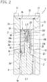
- the gate valve is configured such that as illustrated in Fig. 2 , the valve actuator 5 moves the valve rod 4 and thereby moves the valve plate 3 reciprocally between a close position, indicated by the solid line, at which the gate opening 2 is closed and an open position (retracted position), indicated by the dash-dot-dot line, at which the gate opening 2 is open.
- the valve actuator 5 has a driving mechanism constituted by an air cylinder, a cam mechanism, and other parts. The descriptions of these are omitted here since the structure and operation of the valve actuator 5 are well known.
- the valve box 1 has an external shape of a laterally elongated cuboid, which is formed into a hollow box having front and rear side walls 1a and 1c.
- the front side wall 1a is connected to the vacuum chamber.
- the gate opening 2 shaped like a laterally elongated rectangle is formed in the front side wall 1a.
- a flat valve seat 1b is also formed in the front side wall 1a so as to surround the gate opening 2.
- the gate valve is configured such that at the close position, a sealing member 7 attached to the front surface of the valve plate 3 is pressed against the valve seat 1b by the valve actuator 5 to close the gate opening 2.
- a lid 10 is detachably attached to the upper surface of the valve box 1 with lid fixation screws 11. Removing the lid 10 opens the valve box 1 at the upper surface.
- the valve plate 3 can be detached from the valve rod 4 and taken out of the valve box 1 through a window 12, which is the opening at the upper surface.
- this gate opening 1d and the first gate opening 2 together serve as a passage in the valve box through which things such as works are taken into or out of the vacuum chamber. Note that the gate opening 1d is not the gate that the valve plate 3 opens or closes directly.
- the valve plate 3 has a rectangular and tabular shape elongated laterally and is made of aluminum integrally.
- the valve plate 3 includes a valve front surface 3a to which the sealing member 7 is attached, a valve rear surface 3b that is opposite to the valve front surface 3a, a valve upper surface 3c, and a valve lower surface 3d.
- a mounting hole 13 opens at the valve lower surface 3d.
- the valve front surface 3a, the valve rear surface 3b, the valve upper surface 3c, and the valve lower surface 3d are flat surfaces.
- the valve rod 4 has a mounting portion 14 at the end of the valve rod 4 in the direction of the axis L1 (the upper end in the figures).
- the mounting portion 14 is to be inserted into and fixed to the mounting hole 13.
- the mounting hole 13 has a cross-sectional shape elongated in the longitudinal direction of the valve plate 3 (in the right-left direction in the figures).
- the mounting hole 13 is defined by a front hole-wall surface 13a positioned near the valve front surface 3a, a rear hole-wall surface 13b positioned near the valve rear surface 3b, and right and left side hole-wall surfaces 13c, and a hole end surface 13d positioned at the end of the mounting hole 13 in the depth direction.
- the front hole-wall surface 13a and the rear hole-wall surface 13b are flat surfaces formed parallel to each other, and the side hole-wall surfaces 13c are also flat surfaces formed parallel to each other.
- the hole end surface 13d is a flat surface orthogonally intersecting the front and rear hole-wall surfaces 13a and 13b and the side hole-wall surfaces 13c.
- the mounting hole 13 is formed such that the distance between the front hole-wall surface 13a and the valve front surface 3a is greater than the distance between the rear hole-wall surface 13b and the valve rear surface 3b.
- grooves S are formed respectively at the right and left ends of the front hole-wall surface 13a so as to extend along the axis L1.
- the grooves S are formed only for the purpose of machining the mounting hole 13 in the valve plate 3, of which a detailed description is omitted here.
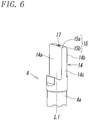
- the valve rod 4 is made of a stainless steel. As illustrated in Figs. 2 to 6 , the valve rod 4 has the mounting portion 14 formed at the end of a column-like main body 4a of the valve rod 4. The mounting portion 14 is to be inserted into the mounting hole 13.
- the mounting portion 14 is shaped like a column that is cut by two parallel flat surfaces along the axis L1 of the valve rod 4.
- the valve rod 4 has a rod front surface 14a that opposes and abuts the front hole-wall surface 13a of the mounting hole 13, a rod rear surface 14b that opposes the rear hole-wall surface 13b of the mounting hole 13, and right and left rod side surfaces 14c that oppose respective right and left side hole-wall surfaces 13c of the mounting hole 13.
- the valve rod 4 also has a rod end surface 15 that serves as the end surface of the mounting portion 14 (in other words, the end surface of the valve rod 4) in the direction of the axis L1.
- the rod front surface 14a and the rod rear surface 14b are flat surfaces extending parallel to each other along the axis L1, and the rod side surfaces 14c are convex surfaces protruding arcuately outward.
- the rod end surface 15 includes an uninclined surface portion 15a and an inclined surface portion 15b.
- the uninclined surface portion 15a extends from the front edge connected to the rod front surface 14a toward the rod rear surface 14b.
- the inclined surface portion 15b extends from the rear edge of the uninclined surface portion 15a and declines toward a base end portion 14d of the mounting portion 14 in such a manner that the width of the mounting portion 14 in the front-rear direction increases gradually.
- the uninclined surface portion 15a extends horizontally so as to orthogonally intersect the axis L1 and a central axis L2 (to be described later).
- the inclined surface portion 15b is formed as a flat surface and the rear edge thereof is connected to the rod rear surface 14b.
- the angle between the uninclined surface portion 15a and the inclined surface portion 15b is an obtuse angle, and preferably approximately 120 degrees.
- the mounting hole 13 and the mounting portion 14 are formed such that a distance W1 between the front hole-wall surface 13a and the rear hole-wall surface 13b is slightly greater than a distance W2 between the rod front surface 14a and the rod rear surface 14b.
- the mounting hole 13 and the mounting portion 14 are formed such that in the state of the valve plate 3 attached to the valve rod 4, the rod front surface 14a of the mounting portion 14 abuts the front hole-wall surface 13a of the mounting hole 13. Accordingly, in the state of the valve plate 3 attached to the valve rod 4, a small space G1 is formed between the rod rear surface 14b and the rear hole-wall surface 13b.
- the width of the space G1 is the difference between W1 and W2 (see Figs. 2 , 8 , and 9 ).
- the length of the mounting portion 14 along the axis L1 is set to be greater than the depth of the mounting hole 13, in other words, greater than the distance between the valve lower surface 3d and the hole end surface 13d.
- the valve plate 3 is attached to the end of the valve rod 4 with a valve-plate fixation screw 20 so as to be detachable in the direction of the axis L1 of the valve rod 4.
- a screw insertion hole 16 for receiving the valve-plate fixation screw 20 is formed at the valve upper surface 3c of the valve plate 3 on an central axis L2 that is parallel to the axis L1.
- a threaded hole 17 is also formed at the rod end surface 15 of the valve rod 4 so that the valve-plate fixation screw 20 can be screwed and engaged tightly with the threaded hole 17.
- a tabularly shaped spacer 30 is interposed between the hole end surface 13d of the mounting hole 13 and the rod end surface 15 of the mounting portion 14 in the state of the valve plate 3 being mounted onto the valve rod 4.
- the central axis L2 is positioned behind the axis L1 of the valve rod 4 (i.e., closer to the rod rear surface 14b) and also behind the center between the valve front surface 3a and the valve rear surface 3b of the valve plate 3 (i.e., closer to the valve rear surface 3b).
- the central axis L2 is positioned in front of the center between the front hole-wall surface 13a and the rear hole-wall surface 13b of the mounting hole 13 (i.e., closer to the front hole-wall surface 13a) and also in front of the center between the rod front surface 14a and the rod rear surface 14b of the mounting portion 14 (i.e., closer to the rod front surface 14a).
- the distance between the central axis L2 and the front hole-wall surface 13a is set to be equal to the distance between the central axis L2 and the rod front surface 14a.
- the mounting portion 14 is thereby positioned appropriately in the mounting hole 13 in the state of the rod front surface 14a abutting the front hole-wall surface 13a when the valve-plate fixation screw 20 is inserted through the screw insertion hole 16 of the valve plate 3 and screwed with the threaded hole 17 of the valve rod 4.
- the central axis L2 is positioned at the center between a pair of side hole-wall surfaces 13c of the mounting hole 13 and also at the center between a pair of the rod side surfaces 14c of the mounting portion 14.
- the valve-plate fixation screw 20 is formed of a screw body 21 around which an external thread is formed and of a manipulation-purpose screw head 22 connected to the base end of the screw body 21.
- the screw body 21 has an external thread portion 21a and a shaft 21b.
- the external thread portion 21a is formed near the end of the screw body 21 and has a thread formed on the circumferential surface thereof.
- the shaft 21b adjoins the external thread portion 21a and is positioned closer to the base end of the screw body 21 with respect to the external thread portion 21a.
- the shaft 21b is shaped like a column (no thread is formed on the circumferential surface).
- the base end of the shaft 21b is joined integrally to the lower surface of the screw head 22.
- a manipulation-purpose hexagon socket 22a opens at the upper surface of the screw head 22.
- a hexagonal wrench 25a is inserted in the hexagon socket 22a for manipulation of the valve-plate fixation screw 20.
- an air hole 23 is formed through the valve-plate fixation screw 20 between the bottom of the manipulation-purpose hexagon socket 22a and the end surface of the screw body 21. Air in the threaded hole 17 can be thereby discharged through the air hole 23 when the valve-plate fixation screw 20 is screwed with the threaded hole 17.
- the outside diameter of the screw head 22 is made greater than the outside diameter d1 of the external thread portion 21a (the diameter of a cylinder virtually formed by connecting ridges of the thread) and is also made greater than the diameter d2 of the shaft 21b.
- the outside diameter d1 of the external thread portion 21a is made greater than the diameter d2 of the shaft 21b.
- the length S1 of the external thread portion 21a is made smaller than the length S2 of the shaft 21b in the direction of the central axis L2.
- the screw insertion hole 16 is penetrated through the valve plate 3 between the valve upper surface 3c and the hole end surface 13d of the mounting hole 13.
- the screw insertion hole 16 has a large diameter section 16a that opens at the valve upper surface 3c so as to accommodate the screw head 22 of the valve-plate fixation screw 20.
- the screw insertion hole 16 also has a small diameter section 16b that is formed between the bottom of the large diameter section 16a and the hole end surface 13d so as to receive the screw body 21 of the valve-plate fixation screw 20 (in other words, the external thread portion 21a and the shaft 21b) inserted therethrough.
- An annular flange 18 is thereby formed in the valve plate 3 between the bottom of the large diameter section 16a and the hole end surface 13d.
- the large diameter section 16a has such an inside diameter and a depth that the screw head 22 and an anti-loosening washer 29 can be completely accommodated together.
- the inside diameter d3 of the small diameter section 16b is made smaller than the inside diameter of the large diameter section 16a and also smaller than the outside diameter of the screw head 22 but is made greater than the outside diameter d1 of the external thread portion 21a of the valve-plate fixation screw 20 and also greater than the diameter d2 of the shaft 21b.
- the inside diameter of the large diameter section 16a is made slightly smaller than the distance W1 between the front hole-wall surface 13a and the rear hole-wall surface 13b and also slightly smaller than the distance W2 between the rod front surface 14a and the rod rear surface 14b.
- the threaded hole 17 has an internal thread section 17a and a cylindrical section 17b.
- the internal thread section 17a has a thread formed on the inner peripheral surface of the threaded hole 17 and is screwed with the external thread portion 21a of the valve-plate fixation screw 20.
- the cylindrical section 17b has a circular cross section having a diameter d4 (in other words, no thread is formed on the inner peripheral surface).
- the cylindrical section 17b is formed so as to open at the uninclined surface portion 15a of the rod end surface 15 and so as to extend from the uninclined surface portion 15a to a length (depth) S3 along the central axis L2.
- the cylindrical section 17b adjoins the internal thread section 17a and is positioned on the side closer to the rod end surface 15.
- the length S3 of the cylindrical section 17b (i.e., the distance between the uninclined surface portion 15a of the rod end surface 15 and the starting end of the internal thread section 17a) is set to be equal to or greater than the length S1 of the external thread portion 21a of the valve-plate fixation screw 20.
- the length of the internal thread section 17a in the direction of the central axis L2 is set to be greater than the length S1 of the external thread portion 21a.
- valve plate 3 when the valve plate 3 is joined to (i.e., fixedly mounted on) the mounting portion 14 of the valve rod 4 and the external thread portion 21a of the valve-plate fixation screw 20 is screwed fixedly with the internal thread section 17a of the threaded hole 17, the entire external thread portion 21a is screwed with the internal thread section 17a.
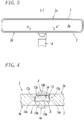
- the spacer 30 is made of stainless steel and formed integrally. As illustrated in Figs. 5 to 9 , the spacer 30 includes a front edge 31 positioned near the rod front surface 14a, a rear edge 32 positioned near the rod rear surface 14b, a pair of side edges 33 positioned near respective rod side surfaces 14c. As viewed in plan, the spacer 30 is shaped like a rectangle elongated in the right-left direction (in a direction parallel to the front edge 31 and to the rear edge 32). In other words, the front edge 31 and the rear edge 32 are formed parallel to each other, and a pair of the side edges 33 are also formed parallel to each other. The side edges 33 are formed at both ends of the front edge 31 and of the rear edge 32, and the angles between the side edges 33 and the front edge 31 and between the side edges 33 and the rear edge 32 are all right angles.
- the spacer 30 has an upper surface 34 to abut the hole end surface 13d and a lower surface 35 to abut the rod end surface 15.
- the upper surface 34 and the lower surface 35 are flat surfaces.
- a through hole 36a is formed on the central axis L2 through the spacer 30 between the upper surface 34 and the lower surface 35.
- the screw body 21 of the valve-plate fixation screw 20 is inserted through the through hole 36a.
- the spacer 30 has a flat plate portion 36 and an engagement protrusion 37.
- the flat plate portion 36 is formed in a front part of the spacer 30 so as to include the upper surface 34, the lower surface 35, and the front edge 31.
- the engagement protrusion 37 is formed at the rear end of the flat plate portion 36, in other words, formed in a rear end part of the spacer 30, so as to include the rear edge 32 and protrude downward.
- the lower surface 35 forms a right angle with the central axis L2 and extends from the front edge 31 toward the rear edge 32 passing the through hole 36a.
- the upper surface 34 inclines slightly (preferably 3 degrees) such that the distance between the upper surface 34 and the lower surface 35 increases gradually from the front edge 31 toward the rear edge 32.
- the upper surface 34 extends from the front edge 31 toward the rear edge 32 passing the central axis L2 (preferably, passing the through hole 36a as in the present embodiment).
- the flat plate portion 36 is formed into a wedge shape of which the thickness in the direction of the central axis L2 gradually increases from the front edge 31 toward the rear edge 32.
- a horizontally elongated gap G2 is formed so as to open in the direction of the central axis L2 between the hole end surface 13d and the rod end surface 15 (preferably formed between the hole end surface 13d and the upper surface 34 of the spacer 30 as in the present embodiment).
- the gap G2 is formed like a wedge shape that opens near the rod front surface 14a and closes at a position near the rod rear surface 14b and behind the central axis L2 (preferably behind the through hole 36a of the spacer 30 as in the present embodiment).
- valve plate 3 When the valve plate 3 is fixedly mounted on (or joined to) the mounting portion 14 of the valve rod 4 and the valve-plate fixation screw 20 is screwed tightly with the threaded hole 17 of the mounting portion 14 as illustrated in Fig. 9 , a fastening force acts on the flange 18 of the valve plate 3 so as to narrow the gap G2 and generate a moment M.
- the moment M causes the front hole-wall surface 13a of the valve plate 3 to press the rod front surface 14a of the valve rod 4.
- a thread is formed on the inner peripheral surface of the through hole 36a in such a manner that the external thread portion 21a of the valve-plate fixation screw 20 can be screwed into and can pass through the through hole 36a.
- the inside diameter d5 of the through hole 36a i.e., the diameter of a cylinder virtually formed by connecting ridges of the thread
- the spacer 30 remains on the shaft 21b without coming off the screw body 21 of the valve-plate fixation screw 20.
- the engagement protrusion 37 has a first surface 37a and a second surface 37b.
- the first surface 37a is formed so as to extend vertically downward from the rear edge 32, whereas the second surface 37b is formed so as to extend obliquely downward from the rear end of the lower surface 35.
- the first surface 37a of the engagement protrusion 37 is brought into contact with the rear hole-wall surface 13b of the mounting hole 13, and the second surface 37b is brought into contact with the inclined surface portion 15b of the rod end surface 15.
- the engagement protrusion 37 is disposed at a position closer than the through hole 36a to the rear edge 32 and formed into a wedge shape of which the width in the front-rear direction (i.e., the distance between the first surface 37a and the second surface 37b) gradually decreases toward the tip pointing downward.
- the valve-plate fixation screw 20 is tightened against the threaded hole 17
- the engagement protrusion 37 is pressed into the wedge-shaped space formed between the inclined surface portion 15b and the rear hole-wall surface 13b.
- the first surface 37a is pressed against the rear hole-wall surface 13b
- the second surface 37b is simultaneously pressed against the inclined surface portion 15b.
- the first surface 37a is a flat surface that forms a right angle with the lower surface 35 (in other words, the first surface 37a is parallel to the central axis L2).
- the angle formed between the first surface 37a and the upper surface 34 is an acute angle, in other words, an angle slightly smaller than the right angle (preferably 87 degrees).
- the second surface 37b is a flat surface forming an obtuse angle, preferably 120 degrees, with the lower surface 35.
- the obtuse angle is set to be equal to the angle formed between the uninclined surface portion 15a and the inclined surface portion 15b of the rod end surface 15.
- the spacer 30 is formed such that the distance between the center of the through hole 36a (i.e., the central axis L2) and the first surface 37a (i.e., the rear edge 32) is set to be equal to the distance between the central axis L2 and the rear hole-wall surface 13b when the rod front surface 14a abuts the front hole-wall surface 13a.
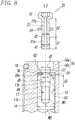
- the following describes a method of attaching and detaching the valve plate 3 to and from the valve rod 4 in the gate valve configured as described above with reference to Figs. 8 to 14 .
- the spacer 30 is first inserted into the mounting hole 13 from the valve lower surface 3d of the valve plate 3 in such a manner that the front edge 31 of the spacer 30 opposes the front hole-wall surface 13a of the mounting hole 13, the rear edge 32 opposes the rear hole-wall surface 13b, and a pair of the side edges 33 oppose respective side hole-wall surfaces 13c.
- the spacer 30 is inserted further until the spacer 30 abuts the hole end surface 13d.
- the mounting portion 14 of the valve rod 4 is also inserted into the mounting hole 13 from the valve lower surface 3d until the rod end surface 15 of the mounting portion 14 abuts the spacer 30 in the mounting hole 13.
- the wedge-shaped gap G2 is formed between the upper surface 34 and the hole end surface 13d so as to open near the rod front surface 14a and so as to close, due to the upper surface 34 abutting the hole end surface 13d, at a position closer to the rod rear surface 14b with respect to the central axis L2 (preferably with respect to the through hole 36a).
- the screw body 21 of the valve-plate fixation screw 20 is inserted into the screw insertion hole 16 of the valve plate 3 from the valve upper surface 3c until the end of external thread portion 21a of the screw body 21 reaches the through hole 36a of the spacer 30.
- the external thread portion 21a is screwed with the thread of the through hole 36a and turned further until the entire external thread portion 21a passes through the through hole 36a and is subsequently accommodated in the cylindrical section 17b of the threaded hole 17.
- the external thread portion 21a is further screwed with the internal thread section 17a of the threaded hole 17 and tightened by applying a predetermined amount of torque.
- a pressing force of the screw head 22 acts on the flange 18 via the washer 29, and the valve plate 3 is thereby joined to the mounting portion 14 of the valve rod 4.
- the position at which the gap G2 closes in the front-rear direction is closer to the rod rear surface 14b with respect to the central axis L2 (preferably with respect to the through hole 36a).
- this generates a counterclockwise moment M in the valve plate 3 with the center being positioned behind the central axis L2 (preferably behind the through hole 36a).
- the moment M slightly deforms the valve plate 3 so as to narrow the gap G2.
- the front hole-wall surface 13a which is in contact with the rod front surface 14a, is pressed against the rod front surface 14a.
- the fastening force generated by tightening the valve-plate fixation screw 20 presses the lower surface 35 of the spacer 30 against the uninclined surface portion 15a of the rod end surface 15 and also presses the engagement protrusion 37 of the spacer 30 into the wedge-shaped space formed between the inclined surface portion 15b of the rod end surface 15 and the rear hole-wall surface 13b of the mounting hole 13.
- the first surface 37a of the spacer 30 is pressed against the rear hole-wall surface 13b and also the second surface 37b is pressed against the inclined surface portion 15b. Consequently, a backward pressing force F acts on the valve plate 3, which further presses the front hole-wall surface 13a of the valve plate 3 against the rod front surface 14a of the valve rod 4.
- the valve plate 3 can be fixed firmly and accurately to the valve rod 4 by using such a simple structure that the spacer 30 is interposed between the rod end surface 15 of the valve rod 4 and the hole end surface 13d of the valve plate 3 and also by using such a simple operation that the valve-plate fixation screw 20 is inserted through the screw insertion hole 16 of the valve plate 3 and screwed tightly with the threaded hole 17 of the valve rod 4. This can prevent particles from being generated due to the valve plate 3 and the valve rod 4 being rubbed against each other during gate valve operation.
- valve plate 3 When the valve plate 3 is detached from the valve rod 4 and taken out of the valve box 1 during a maintenance operation, for example, for replacing the sealing member 7 of the valve plate 3, the valve plate 3 is first moved down as illustrated in Fig. 10 by actuating the valve actuator 5 from an upper position (close position), which is indicated by the solid line in Fig. 2 , to a lower position (retracted position), which is indicated by the dash-dot-dot line in Fig. 2 .
- the lid 10 is detached by removing the lid fixation screws 11 from the upper surface of the valve box 1 to open the window 12 at the upper surface.
- valve-plate fixation screw 20 is loosened by using a hexagonal wrench 25a inserted through the window 12.
- the external thread portion 21a is thereby unscrewed from the internal thread section 17a of threaded hole 17 of the valve rod 4, and the entire external thread portion 21a is accommodated in the cylindrical section 17b.
- valve plate 3 is pulled up with both hands holding the gripping tools 25b. This enables the valve plate 3 to be detached from the valve rod 4 and taken out through the window 12 opening at the upper surface of the valve box 1.
- the inner peripheral surface of through hole 36a of the spacer 30 has the thread to be screwed with the external thread portion 21a of the valve-plate fixation screw 20, and the inside diameter d5 of the through hole 36a is made smaller than the outside diameter d1 of the external thread portion 21a.
- valve plate 3 is returned to the valve box 1 by attaching the two gripping tools 25b again to the corresponding tool insertion holes 26 and by holding the gripping tools 25b by hand.
- the gripping tools 25b are removed after the mounting portion 14 of the valve rod 4 is inserted into the mounting hole 13 of the valve plate 3.
- the valve-plate fixation screw 20 is screwed with the threaded hole 17 and tightened by using the hexagonal wrench 25a.
- the valve plate 3 is fixed to the valve rod 4.
- the lid 10 is attached to the upper surface of the valve box 1 with the lid fixation screws 11.
- the gate valve becomes usable again in the state illustrated in Fig. 10 .
- the spacer 30 configured as described above is not necessarily provided between the rod end surface 15 and the hole end surface 13d in order to form the gap G2.
- the gap G2 may be formed by the hole end surface 13d and the rod end surface 15 on which an inclined surface is formed.
- one spacer 30 generates both the moment M and the pressing force F as illustrated in Fig. 9 , but the moment M and the pressing force F may be generated by separate members.
Landscapes
- Engineering & Computer Science (AREA)
- General Engineering & Computer Science (AREA)
- Mechanical Engineering (AREA)
- Sliding Valves (AREA)
- Details Of Valves (AREA)
- Lift Valve (AREA)
Applications Claiming Priority (1)
| Application Number | Priority Date | Filing Date | Title |
|---|---|---|---|
| JP2019113993A JP7385185B2 (ja) | 2019-06-19 | 2019-06-19 | ゲート弁における弁ロッドに対する弁板の取付構造、及びその取付構造を有するゲート弁 |
Publications (1)
| Publication Number | Publication Date |
|---|---|
| EP3754239A1 true EP3754239A1 (de) | 2020-12-23 |
Family
ID=70977424
Family Applications (1)
| Application Number | Title | Priority Date | Filing Date |
|---|---|---|---|
| EP20178027.7A Pending EP3754239A1 (de) | 2019-06-19 | 2020-06-03 | Montagestruktur zur montage einer ventilplatte an einer ventilstange in einem schieberventil sowie ein schieberventil mit der montagestruktur |
Country Status (6)
| Country | Link |
|---|---|
| US (1) | US11174950B2 (de) |
| EP (1) | EP3754239A1 (de) |
| JP (1) | JP7385185B2 (de) |
| KR (1) | KR20200145695A (de) |
| CN (1) | CN112112993B (de) |
| TW (1) | TWI849141B (de) |
Cited By (3)
| Publication number | Priority date | Publication date | Assignee | Title |
|---|---|---|---|---|
| EP3936744A1 (de) * | 2020-06-16 | 2022-01-12 | SMC Corporation | Schieberventil |
| EP4098919A1 (de) * | 2021-06-04 | 2022-12-07 | VAT Holding AG | Ventilplatte zum abdichten einer ventilöffnung eines vakuumventils |
| WO2025027164A1 (de) * | 2023-08-03 | 2025-02-06 | Vat Holding Ag | Koppelungssystem für ventilteller und vakuumventil |
Families Citing this family (7)
| Publication number | Priority date | Publication date | Assignee | Title |
|---|---|---|---|---|
| JP7537329B2 (ja) * | 2021-03-19 | 2024-08-21 | Smc株式会社 | ぶれ防止機構付きゲートバルブ |
| JP7636714B2 (ja) * | 2021-04-20 | 2025-02-27 | Smc株式会社 | ゲートバルブ |
| DE102021117955A1 (de) | 2021-07-12 | 2023-01-12 | Vat Holding Ag | Ventil |
| DE102021129883A1 (de) * | 2021-11-16 | 2023-05-17 | Vat Holding Ag | Ventilplatte |
| DE102021129884A1 (de) | 2021-11-16 | 2023-05-17 | Vat Holding Ag | Ventilplatte |
| KR102427175B1 (ko) * | 2021-11-25 | 2022-07-29 | 주식회사 에스에스케이 | 진공 게이트밸브용 밸브조립체 |
| JP2026049808A (ja) * | 2024-09-09 | 2026-03-19 | Smc株式会社 | ゲート及びスリットバルブ |
Citations (3)
| Publication number | Priority date | Publication date | Assignee | Title |
|---|---|---|---|---|
| JP2005291221A (ja) | 2004-03-31 | 2005-10-20 | Vat Holding Ag | 真空ゲートバルブ、バルブ板および多機能工具 |
| US20110095218A1 (en) * | 2009-10-27 | 2011-04-28 | Vat Holding Ag | Closing unit for a vacuum valve |
| US20110108750A1 (en) * | 2008-12-11 | 2011-05-12 | Vat Holding Ag | Mounting of a valve plate on a valve rod |
Family Cites Families (19)
| Publication number | Priority date | Publication date | Assignee | Title |
|---|---|---|---|---|
| DE60012428T2 (de) * | 1999-06-14 | 2005-07-28 | Smc K.K. | Schieber |
| JP4602019B2 (ja) * | 2003-08-26 | 2010-12-22 | 株式会社キッツエスシーティー | ゲートバルブ |
| US7100892B2 (en) * | 2003-08-26 | 2006-09-05 | Kitz Sct Corporation | Non-rubbing gate valve for semiconductor fabrication apparatus |
| KR100960030B1 (ko) * | 2004-03-12 | 2010-05-28 | 배트 홀딩 아게 | 진공 게이트 밸브 |
| JP5811320B2 (ja) * | 2011-04-21 | 2015-11-11 | Smc株式会社 | ゲートバルブ |
| JP6150388B2 (ja) * | 2013-06-05 | 2017-06-21 | 入江工研株式会社 | ゲートバルブ及びチャンバ |
| CN103742661A (zh) * | 2014-01-24 | 2014-04-23 | 蒋正权 | 陶瓷滑板控制阀 |
| EP2913573A1 (de) * | 2014-02-26 | 2015-09-02 | VAT Holding AG | Vakuumventil |
| TWI540277B (zh) * | 2015-01-07 | 2016-07-01 | 新萊應材科技有限公司 | 連桿閘板閥 |
| US10197183B2 (en) * | 2015-02-12 | 2019-02-05 | Fisher Controls International Llc | Valve stem and plug connections and staking tools |
| JP6485689B2 (ja) * | 2015-02-12 | 2019-03-20 | Smc株式会社 | ゲートバルブ |
| JP2016160990A (ja) * | 2015-02-27 | 2016-09-05 | 新▲莱▼應材科技有限公司 | リンク付きゲート弁 |
| JP5890929B1 (ja) * | 2015-07-01 | 2016-03-22 | 株式会社ブイテックス | ゲートバルブ |
| CN205559829U (zh) * | 2015-12-03 | 2016-09-07 | 潘健 | 一种模块组合式阀体密封环可更换闸板阀 |
| CN205678155U (zh) * | 2016-06-17 | 2016-11-09 | 嵊州市龙威阀门有限公司 | 一种闸阀 |
| CN106321866A (zh) * | 2016-08-31 | 2017-01-11 | 渤海阀门集团有限公司 | 闸阀 |
| WO2018093384A1 (en) * | 2016-11-18 | 2018-05-24 | Fmc Technologies, Inc. | Valve with friction reducing dimpled sealing surfaces |
| JP6388182B1 (ja) * | 2017-07-25 | 2018-09-12 | Smc株式会社 | ゲートバルブの取付構造 |
| JP7057584B2 (ja) * | 2018-01-10 | 2022-04-20 | Smc株式会社 | 弁ロッドに対する弁板の取付構造 |
-
2019
- 2019-06-19 JP JP2019113993A patent/JP7385185B2/ja active Active
-
2020
- 2020-06-03 EP EP20178027.7A patent/EP3754239A1/de active Pending
- 2020-06-10 KR KR1020200070075A patent/KR20200145695A/ko not_active Ceased
- 2020-06-11 TW TW109119607A patent/TWI849141B/zh active
- 2020-06-18 US US16/905,299 patent/US11174950B2/en active Active
- 2020-06-19 CN CN202010563478.0A patent/CN112112993B/zh active Active
Patent Citations (3)
| Publication number | Priority date | Publication date | Assignee | Title |
|---|---|---|---|---|
| JP2005291221A (ja) | 2004-03-31 | 2005-10-20 | Vat Holding Ag | 真空ゲートバルブ、バルブ板および多機能工具 |
| US20110108750A1 (en) * | 2008-12-11 | 2011-05-12 | Vat Holding Ag | Mounting of a valve plate on a valve rod |
| US20110095218A1 (en) * | 2009-10-27 | 2011-04-28 | Vat Holding Ag | Closing unit for a vacuum valve |
Cited By (5)
| Publication number | Priority date | Publication date | Assignee | Title |
|---|---|---|---|---|
| EP3936744A1 (de) * | 2020-06-16 | 2022-01-12 | SMC Corporation | Schieberventil |
| US11402024B2 (en) | 2020-06-16 | 2022-08-02 | Smc Corporation | Gate valve |
| EP4098919A1 (de) * | 2021-06-04 | 2022-12-07 | VAT Holding AG | Ventilplatte zum abdichten einer ventilöffnung eines vakuumventils |
| US11725739B2 (en) | 2021-06-04 | 2023-08-15 | Vat Holding Ag | Valve plate for sealing a valve opening of a vacuum valve |
| WO2025027164A1 (de) * | 2023-08-03 | 2025-02-06 | Vat Holding Ag | Koppelungssystem für ventilteller und vakuumventil |
Also Published As
| Publication number | Publication date |
|---|---|
| US20200400238A1 (en) | 2020-12-24 |
| CN112112993B (zh) | 2023-12-12 |
| TWI849141B (zh) | 2024-07-21 |
| TW202113258A (zh) | 2021-04-01 |
| KR20200145695A (ko) | 2020-12-30 |
| US11174950B2 (en) | 2021-11-16 |
| JP7385185B2 (ja) | 2023-11-22 |
| CN112112993A (zh) | 2020-12-22 |
| JP2021001613A (ja) | 2021-01-07 |
Similar Documents
| Publication | Publication Date | Title |
|---|---|---|
| US11174950B2 (en) | Mounting structure for mounting valve plate to valve rod in gate valve, and gate valve having mounting structure | |
| TWI558922B (zh) | 螺栓鬆弛防止裝置及其安裝方法、第1、第2安裝治具、流體控制裝置及基板處理裝置 | |
| EP4379243B1 (de) | Montagestruktur einer ventilplatte in bezug auf eine ventilstange | |
| US8262329B2 (en) | Fastening device | |
| US20150152901A1 (en) | Fastening arrangement, portable working tool and method of fastening a first housing section to a second housing section | |
| CN110799761A (zh) | 紧固装置 | |
| JP5235237B1 (ja) | 二重ナット | |
| US20160238150A1 (en) | Gate valve | |
| KR20210076650A (ko) | 단차 조절이 가능한 차량의 부품체결 구조 | |
| US11407072B2 (en) | Clamp for retaining a block of material on a machining table, clamping device comprising said clamp and method of clamping a block of material, onto a machining table | |
| KR20100011234U (ko) | 칸막이용 프레임의 연결장치 | |
| US20050000327A1 (en) | Adjustable socket | |
| JP4422447B2 (ja) | エジェクターユニットの取付方法 | |
| JP2004522605A (ja) | 切削加工用工具 | |
| KR0122045Y1 (ko) | 볼트체결용 공구 | |
| US9441400B2 (en) | Closure latch | |
| TWM677407U (zh) | 偏心螺絲 | |
| CN203357356U (zh) | 锁固螺丝或螺帽的省力辅助件 | |
| JPH10306819A (ja) | 緩み止め部材および緩み止めナット | |
| NO342065B1 (no) | Bolt med sikringsanordning for et bolthode og framgangsmåte for demontering av bolten | |
| JP2006316986A (ja) | 螺締具用、突起付き円柱形座金と溝付きボルト | |
| JPH0651527U (ja) | Tナット | |
| JP2005048807A (ja) | 緩み防止ナット | |
| JP2005014271A (ja) | 金型のセンターピン回り止め機構 | |
| KR19980018293U (ko) | 자동차의 탭 작업용 보조 기구 |
Legal Events
| Date | Code | Title | Description |
|---|---|---|---|
| PUAI | Public reference made under article 153(3) epc to a published international application that has entered the european phase |
Free format text: ORIGINAL CODE: 0009012 |
|
| STAA | Information on the status of an ep patent application or granted ep patent |
Free format text: STATUS: THE APPLICATION HAS BEEN PUBLISHED |
|
| AK | Designated contracting states |
Kind code of ref document: A1 Designated state(s): AL AT BE BG CH CY CZ DE DK EE ES FI FR GB GR HR HU IE IS IT LI LT LU LV MC MK MT NL NO PL PT RO RS SE SI SK SM TR |
|
| AX | Request for extension of the european patent |
Extension state: BA ME |
|
| STAA | Information on the status of an ep patent application or granted ep patent |
Free format text: STATUS: REQUEST FOR EXAMINATION WAS MADE |
|
| 17P | Request for examination filed |
Effective date: 20210622 |
|
| RBV | Designated contracting states (corrected) |
Designated state(s): AL AT BE BG CH CY CZ DE DK EE ES FI FR GB GR HR HU IE IS IT LI LT LU LV MC MK MT NL NO PL PT RO RS SE SI SK SM TR |
|
| STAA | Information on the status of an ep patent application or granted ep patent |
Free format text: STATUS: EXAMINATION IS IN PROGRESS |
|
| 17Q | First examination report despatched |
Effective date: 20230525 |
|
| RAP3 | Party data changed (applicant data changed or rights of an application transferred) |
Owner name: SMC CORPORATION |
|
| REG | Reference to a national code |
Ref country code: DE Ref legal event code: R079 Ref document number: 602020071998 Country of ref document: DE Free format text: PREVIOUS MAIN CLASS: F16K0051020000 Ipc: F16K0003020000 Ref country code: DE Ref legal event code: R079 Free format text: PREVIOUS MAIN CLASS: F16K0051020000 Ipc: F16K0003020000 |
|
| GRAP | Despatch of communication of intention to grant a patent |
Free format text: ORIGINAL CODE: EPIDOSNIGR1 |
|
| STAA | Information on the status of an ep patent application or granted ep patent |
Free format text: STATUS: GRANT OF PATENT IS INTENDED |
|
| RIC1 | Information provided on ipc code assigned before grant |
Ipc: F16K 3/02 20060101AFI20250702BHEP Ipc: F16K 51/02 20060101ALI20250702BHEP Ipc: F16K 3/314 20060101ALI20250702BHEP |
|
| INTG | Intention to grant announced |
Effective date: 20250716 |
|
| RIN1 | Information on inventor provided before grant (corrected) |
Inventor name: SHIMODA, HIROMI Inventor name: OGAWA, HIROSHI Inventor name: NAGAO, TAKASHI Inventor name: OCHI, TSUYOSHI |
|
| GRAJ | Information related to disapproval of communication of intention to grant by the applicant or resumption of examination proceedings by the epo deleted |
Free format text: ORIGINAL CODE: EPIDOSDIGR1 |
|
| STAA | Information on the status of an ep patent application or granted ep patent |
Free format text: STATUS: EXAMINATION IS IN PROGRESS |
|
| INTC | Intention to grant announced (deleted) | ||
| GRAP | Despatch of communication of intention to grant a patent |
Free format text: ORIGINAL CODE: EPIDOSNIGR1 |
|
| STAA | Information on the status of an ep patent application or granted ep patent |
Free format text: STATUS: GRANT OF PATENT IS INTENDED |
|
| INTG | Intention to grant announced |
Effective date: 20251223 |
|
| GRAS | Grant fee paid |
Free format text: ORIGINAL CODE: EPIDOSNIGR3 |
|
| GRAA | (expected) grant |
Free format text: ORIGINAL CODE: 0009210 |
|
| STAA | Information on the status of an ep patent application or granted ep patent |
Free format text: STATUS: THE PATENT HAS BEEN GRANTED |