EP3751094B1 - Couplings for coupling pre-cast construction segments together and pre-cast construction segments having such couplings - Google Patents
Couplings for coupling pre-cast construction segments together and pre-cast construction segments having such couplings Download PDFInfo
- Publication number
- EP3751094B1 EP3751094B1 EP20173523.0A EP20173523A EP3751094B1 EP 3751094 B1 EP3751094 B1 EP 3751094B1 EP 20173523 A EP20173523 A EP 20173523A EP 3751094 B1 EP3751094 B1 EP 3751094B1
- Authority
- EP
- European Patent Office
- Prior art keywords
- central portion
- anchor
- anchors
- pin
- segments
- Prior art date
- Legal status (The legal status is an assumption and is not a legal conclusion. Google has not performed a legal analysis and makes no representation as to the accuracy of the status listed.)
- Active
Links
Images


Classifications
-
- E—FIXED CONSTRUCTIONS
- E04—BUILDING
- E04B—GENERAL BUILDING CONSTRUCTIONS; WALLS, e.g. PARTITIONS; ROOFS; FLOORS; CEILINGS; INSULATION OR OTHER PROTECTION OF BUILDINGS
- E04B1/00—Constructions in general; Structures which are not restricted either to walls, e.g. partitions, or floors or ceilings or roofs
- E04B1/38—Connections for building structures in general
- E04B1/41—Connecting devices specially adapted for embedding in concrete or masonry
- E04B1/4114—Elements with sockets
-
- E—FIXED CONSTRUCTIONS
- E21—EARTH OR ROCK DRILLING; MINING
- E21D—SHAFTS; TUNNELS; GALLERIES; LARGE UNDERGROUND CHAMBERS
- E21D11/00—Lining tunnels, galleries or other underground cavities, e.g. large underground chambers; Linings therefor; Making such linings in situ, e.g. by assembling
- E21D11/04—Lining with building materials
- E21D11/08—Lining with building materials with preformed concrete slabs
- E21D11/083—Methods or devices for joining adjacent concrete segments
-
- E—FIXED CONSTRUCTIONS
- E21—EARTH OR ROCK DRILLING; MINING
- E21D—SHAFTS; TUNNELS; GALLERIES; LARGE UNDERGROUND CHAMBERS
- E21D11/00—Lining tunnels, galleries or other underground cavities, e.g. large underground chambers; Linings therefor; Making such linings in situ, e.g. by assembling
- E21D11/04—Lining with building materials
- E21D11/08—Lining with building materials with preformed concrete slabs
- E21D11/086—Methods of making concrete lining segments
-
- B—PERFORMING OPERATIONS; TRANSPORTING
- B28—WORKING CEMENT, CLAY, OR STONE
- B28B—SHAPING CLAY OR OTHER CERAMIC COMPOSITIONS; SHAPING SLAG; SHAPING MIXTURES CONTAINING CEMENTITIOUS MATERIAL, e.g. PLASTER
- B28B23/00—Arrangements specially adapted for the production of shaped articles with elements wholly or partly embedded in the moulding material; Production of reinforced objects
- B28B23/005—Arrangements specially adapted for the production of shaped articles with elements wholly or partly embedded in the moulding material; Production of reinforced objects with anchoring or fastening elements for the shaped articles
-
- E—FIXED CONSTRUCTIONS
- E04—BUILDING
- E04B—GENERAL BUILDING CONSTRUCTIONS; WALLS, e.g. PARTITIONS; ROOFS; FLOORS; CEILINGS; INSULATION OR OTHER PROTECTION OF BUILDINGS
- E04B1/00—Constructions in general; Structures which are not restricted either to walls, e.g. partitions, or floors or ceilings or roofs
- E04B1/02—Structures consisting primarily of load-supporting, block-shaped, or slab-shaped elements
- E04B1/04—Structures consisting primarily of load-supporting, block-shaped, or slab-shaped elements the elements consisting of concrete, e.g. reinforced concrete, or other stone-like material
- E04B1/043—Connections specially adapted therefor
-
- E—FIXED CONSTRUCTIONS
- E21—EARTH OR ROCK DRILLING; MINING
- E21D—SHAFTS; TUNNELS; GALLERIES; LARGE UNDERGROUND CHAMBERS
- E21D11/00—Lining tunnels, galleries or other underground cavities, e.g. large underground chambers; Linings therefor; Making such linings in situ, e.g. by assembling
-
- E—FIXED CONSTRUCTIONS
- E04—BUILDING
- E04B—GENERAL BUILDING CONSTRUCTIONS; WALLS, e.g. PARTITIONS; ROOFS; FLOORS; CEILINGS; INSULATION OR OTHER PROTECTION OF BUILDINGS
- E04B1/00—Constructions in general; Structures which are not restricted either to walls, e.g. partitions, or floors or ceilings or roofs
- E04B1/38—Connections for building structures in general
- E04B1/41—Connecting devices specially adapted for embedding in concrete or masonry
- E04B1/4114—Elements with sockets
- E04B1/415—Elements with sockets with captive and extendable anchoring parts, e.g. spring-loaded bolts, hanging rings
Definitions
- the present disclosure relates generally to construction couplings and, in particular, to construction couplings for coupling pre-cast construction segments such as ring segments together and construction segments having such couplings.
- Tunnels can be built by assembling and securing a plurality of pre-cast rings adjacent one another along an axis of the tunnel to be formed, see FR2400650 .
- pre-cast rings can each include a plurality of pre-cast arcuate-shaped ring segments coupled together.
- Each ring segment includes opposite radial end surfaces that engage corresponding radial end surfaces of adjoining ring segments to define radial joints.
- the ring segments must be coupled together at the radial joints with bolts or other means to prevent relative movement between the ring segments.
- the process of bolting the ring segments together is relatively labor intensive and the bolts may be susceptible to corrosion.
- the examples disclosed herein relate to couplings for joining segments together.
- the segments can be ring segments, tunnel segments, building segments, etc.
- the couplings provide a hinge-like structure and are relatively easy to align when coupling the segments together. As a result, the segments can be assembled in less time with less man power as compared to conventional methods. Additionally, the couplings provide a relatively high pull-out resistance and a relatively high shear resistance. Having a higher pull-out resistance and/or a higher shear resistance may be advantageous when the couplings are used in environments in which the internal pressure of the structure (e.g., the tunnel) formed by the segments is higher than the external pressure of the structure and/or when the environment poses seismic-event risks.
- the internal pressure of the structure e.g., the tunnel
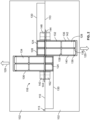
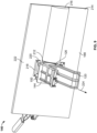
- Fig. 1 is an isometric view of a pre-cast, pre-assembled ring 100 of a tunnel, for example, in accordance with a first disclosed example.
- the ring 100 includes a plurality of common ring segments 102 and a key ring segment (a key stone) 104.
- the segments 102, 104 are pre-cast concrete forms including opposite axial end faces 106, 108 and radial end surfaces 110, 112.
- the segments 102, 104 are configured such that when assembled in a manner shown in Fig. 1 , the radial end surfaces 110, 112 abut each other to form a complete circle that defines the ring 100.
- a plurality of the rings 100 are positioned in a manner to form longitudinal joints between opposing axial end faces 106, 108 of the respective rings 100.
- fasteners (not shown) would be used to couple the rings together.
- the common ring segments 102 and the key ring segment 104 are similar or the same to one another and the key ring segment 104 has a shorter radial dimension than the common ring segments 102.
- radial joints 113 are formed.
- the radial joints 113 are defined along or are otherwise associated with a radial vector 114 of the ring 100.
- the radial joints 113 between the common ring segments 102 and the key ring segment 104 may be defined at an angle different than an angle defined at the radial joints 113 between the radial end surfaces 110 of two adjacent common ring segments 102.
- the segments 102, 104 are coupled together at the radial end surfaces 110, 112 via a plurality of radial couplings 116.
- Two radial couplings 116 couple the ring segments 102, 104 together at the radial joints 113.
- a different number of the radial couplings 116 may be included instead.
- each of the radial joints 113 may include one, three, four, five, etc., radial couplings 116.
- each radial coupling 116 includes two anchors 120 and a pin 122.
- the anchors 120 have a central portion 124 defining a blind bore 126 and also include a pair of legs 128 that extend from the central portion 124.
- the pin 122 is sized to be received within the bores 126 to couple the anchors 120 together.
- the abutting radial end surfaces 110 of two of the common ring segments 102 are shown forming one of the radial coupling 116 where the pin 122 is received within the bores 126 of the anchors 120.
- the radial coupling 116 provides a pull-out resistance of between about approximately 100 kilonewtons and approximately 400 kilonewtons and a shear resistance of between about approximately 100 kilonewtons and approximately 400 kilonewtons.
- the pull-out resistance is represented by forces applied to the anchors 120 in a direction generally represented by arrows 129 and the shear resistance is associated with forces applied to the anchors 120 in a direction generally opposite and 90° relative to the arrows 129.
- each radial end surface 110 includes a pair of recesses 130.
- the recesses 130 have a semi-cylindrical shape and are sized to receive the pin 122 and the central portion 124 of the radial coupling 116, as will be described further below.
- the recesses 130 are also sized to allow relative movement between the ring segments 102, 104 while and/or after the ring segments 102, 104 are coupled together, as will also be described below.
- the recesses 130 may have a different cross-section and/or shape than being semi-cylindrical.
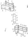
- the radial coupling 116 includes the anchors 120 and the pin 122 (the pin 122 is most clearly shown in Fig. 3 ).
- the anchors 120 are substantially similar to one another and are substantially symmetric along a vertical plane perpendicular to the radial end surfaces 110.
- the anchors 120 are generally omega shaped.
- the anchors 120 may be a different shape.
- the anchors 120 may be U-shaped, V-shaped, W-shaped, etc.
- the anchors 120 include the central portion 124 and the pair of legs 128 (the legs 128 are most clearly shown in Figs. 2 and 3 ).
- the legs 128 extend from opposing sides of the central portion 124 at an angle ⁇ relative to a centerline CL of the anchors 120.
- the angle ⁇ may be about 45°.
- the angle defined between the legs 128 is between about 45° and 90°.
- any angle between about 0° and about 90° has been contemplated.
- the angle defined between the legs 128 may be about 30°, about 40°, about 47°, about 62°, about 70°, about 93°, etc.
- the legs 128 of the anchors 120 include a plurality of reinforcing ribs 132 and a panel 134 from which the ribs 132 extend.
- the ribs 132 include a plurality of longitudinal ribs 136 and a plurality of lateral ribs 138 intersecting the longitudinal ribs 136.
- the longitudinal ribs 136 wrap around the anchor 120 to form a substantially omega-shape. Two of the longitudinal ribs 136 are disposed along a perimeter of the anchor 120 and one of the longitudinal ribs 136 is positioned between the exterior longitudinal ribs 127.
- the lateral ribs 138 extend between sides 140, 142 of the legs 128.
- the lateral ribs 138 also extend between the longitudinal ribs 136. While three longitudinal ribs 136 and five lateral ribs 138 are included in the anchors 120 illustrated (see, Fig. 3 for additional clarity), any other number of ribs 132 may be included instead.
- the anchors 120 may include four longitudinal ribs 136 and 7 lateral ribs 138. In other versions, the anchors may not include ribs at all, but rather, the legs can simply include the flat panels.
- a first portion 143 of the central portion 124 includes a flange 144 (the flange is most clearly shown in Fig. 3 ).
- the flange 144 is formed by one of the lateral ribs 138. As shown in the example of Fig. 2 , the flange 144 is positioned within a dimensional envelope of the associated ring segments 102.
- the flange 144 can be used by a fixation tool 146 (See, Fig. 8 ) to hold the anchor 120 in place during a pre-cast concreting process during which the anchor 120 is embedded within the ring segment 102.
- the fixation tool 146 also allows the anchor 120 to be consistently positioned within the ring segment 102 when the ring segments 102 are formed and when the anchors 120 are coupled within the ring segments 102.
- a second portion 148 of the central portion 124 of the anchor 120 extends from the ring segments 102.
- a plane defined by and/or between the radial end surfaces 110 bisects the first and second portions 143, 148 of the anchor 120.
- approximately half of the central portion 124 is within a dimensional envelope of the ring segment 102 and approximately half of the central portion 124 extends out of the dimensional envelope of the ring segment 102.
- Positioning the second portion 148 to extend from the ring segments 102 allows the second portion 148 of the anchor 120 to be received within the recess 130 of the adjacent ring segments 102 during the coupling process.
- the central portions 124 and the associated bores 126 of the anchors 120 are coaxially aligned.
- an expanded isometric view of the radial coupling 116 is depicted including the anchors 120 and the pin 122.
- the anchors 120 do not include a plurality of break-away segments 150 (the break-away segments are most clearly shown in Fig. 6 ) because the break-away segments 150 have been broken off from the flange 144.
- the break-away segments 150 are further described in connection with Figs. 6 -12 .
- the pin 122 has a central portion 152, a plurality of tapered portions 153 and a plurality of distal portions 154.
- the tapered portions 153 are positioned between the central portion 124 and the associated distal portions 154.
- the central portion 124 has a larger diameter than the distal portions 154 and the distal portions 154 have rounded ends and/or edges.
- the pin 122 is sized to be received within a plurality of diameter portions 156, 158 of the bores 126 of the anchor 120 (the diameter portions 156, 158 of the bore 126 are most clearly shown in Fig. 5 ).
- the second portion 148 of the anchor 120 includes a protrusion 162 and the legs 128 include an inner side 164 and an outer side 166.
- the inner side 164 is relatively smooth between the sides 140, 142 of the legs 128.
- the ribs 132 project from the outer side 166.
- Each leg 128 also includes a tongue 168, which extends transversely outward from the leg 128.
- the tongues 168 interact with the material forming the ring segments 102, 104 to reduce the likelihood that the anchors 120 are inadvertently removed from the ring segments 102,104.
- the flange 144 extends around three sides of the anchor 120. Specifically, the flange 144 extends between the first and second sides 140, 142 of the legs 128 and around the protrusion 162 of the central portion 124. As described in connection with Figs. 6 -12 , the flange 144 can be used by the fixation tool 146 (See, Fig. 8 ) to hold the anchor 120 in place during a pre-cast concreting process during which the anchor 120 is embedded within the ring segment 102.
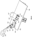
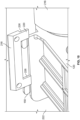
- Fig. 4 illustrates a detailed isometric view of one radial end surface 110 of the ring segments 102, 104 defining the recess 130 and including one of the embedded anchors 120.
- the bore 126 of the anchor 120 opens into the recess 130
- the first portion 143 of the central portion 124 of the anchor 120 is received by the ring segment 102
- the second portion 148 of the central portion 124 of the anchor 120 extends from the radial end surface 110.
- the pin 122 and the anchor 120 carried by the other ring segment 102, 104 are able to be positioned within and moved along the recess 30 during the coupling process.
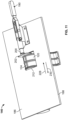
- Fig. 5 is a cross-sectional view of the radial coupling 116 after assembly showing the pin 122 being received by the bores 126 of two of the anchors 120.
- the central portion 152 of the pin 122 is shown positioned within the first diameter portion 156 of the bore 126 of the anchor 120 and the distal portions 154 of the pin 122 are shown received within the second diameter portions 158 of the bore 126 of the anchor 120.
- the first diameter portion 156 of the bore 126 is defined by the central portion 124 of the anchor 120 and is positioned substantially between the sides 140, 142 of the legs 128 and the second diameter portion 158 of the bore 126 is defined by the protrusion 162 of the central portion 124 that extends beyond the side 142 of the leg 128.
- an interior surface 170 that defines the bore 126 of the anchor 120 is tapered.
- the interior surface 170 may be engaged by the pin 122 to guide the distal portion 154 of the pin 122 within the second diameter portion 158.
- a seal formed between the pin 122 and the interior surface 170 deters the ingress of fluid (e.g., water) within the coupling and/or the anchor 120 that may cause damage (e.g., erosion, etc.).
- Fig. 6 illustrates an isometric view of one of the anchors 120.
- the anchor 120 of Fig. 6 includes the break-away segments 150.
- the break-away segments 150 are used during the pre-cast concreting process to hold the anchor 120 in place as further described in connection with Figs. 8 - 12 .
- the break-away segments 150 are tabs that laterally extend from the flange 144 on a first side 172 of the anchor 120 and a second side 174 of the anchor 120 but are not positioned on a third side 176 of the anchor 120.
- Fig. 7 illustrates a detailed view of the anchor 120 of Fig. 6 .
- the break-away segments 150 include a plurality of notches 184.
- the notches 184 are V-shaped and are positioned immediately adjacent the flange 144.
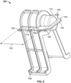
- Fig. 8 is an isometric view of a first side 186 of the fixation tool 146 and one of the anchors 120.
- the fixation tool 146 includes a base 188 and a lever assembly 190 coupled to the base 188.
- the base 188 defines an aperture 192.
- the central portion 124 of the anchor 120 is positioned within and extends through the aperture 192.
- the lever assembly 190 includes a handle 194, a link 196, a guide 198, a rod 200 and an engagement surface 202.
- the handle 194 is pivotably coupled to a distal end 204 of the rod 200 and is also pivotably coupled to the link 196.
- the link 196 is pivotably coupled to a portion 206 of the guide 198.
- the rod 200 is partially positioned within the guide 198 and is coupled to the engagement surface 202.
- the handle 194 is moved in a direction generally indicated by arrow 208, causing the handle 194 to pivot relative to the rod 200 and the link 196 and for the rod 200 and the engagement surface 202 to move in a direction generally indicated by arrow 210.
- the lever assembly 190 is in an open position and the anchor 120 is spaced from a front edge / surface 212 of the base 188 that defines the aperture 192.
- the engagement surface 202 of the lever assembly 190 is spaced from the anchor 120.
- Fig. 9 is an isometric view of a second side 214 of the fixation tool 146.
- the base 188 includes a semi-cylindrical portion 216 and holders 218 having tabs 220.
- the semi-cylindrical portion 216 faces the bore 126 of the anchor 120 and is adapted to form the recess 130 during the pre-cast concreting process.
- the tabs 220 are spaced from a surface 222 of the base 188 (more clearly shown in Fig. 10 ) to allow the break-away segments 150 to be slid under the tabs 220 when the lever assembly 190 is in the closed position.
- Positioning the break-away segments 150 between the tab 220 and the base 188 prevents the anchor 120 from moving out of the aperture 192 of the fixation tool 146 in a direction generally represented by arrow 224 once the anchor 120 is fixed within the fixation tool 146.
- the flange 144 is shown engaging the surface 222 of the base 188 adjacent the aperture 192. The interaction between the flange 144 and the base 188 prevents the anchor 120 from moving further into the aperture 192 of the base 188 in a direction generally opposite that indicated by the arrow 224.
- Fig. 10 is a detailed isometric view of the holder 218, the tabs 220 and the break-away segments 150.
- a plurality of slots 226 are formed between the tabs 220 and the base 188. The slots 226 allow the break-away segments 150 to be received between the tabs 220 and the surface 222 of the base 188 when the anchor 120 is fixed within the fixation tool 146 and the lever assembly 190 is in the closed position.
- Fig. 11 is an isometric view of the first side 186 of the fixation tool 146 and one of the anchors 120.
- the lever assembly 190 is in the closed position and the rod 200 and the engagement surface 202 are in the extended position.
- the central portion 124 of the anchor 120 is clamped between the engagement surface 202 of the lever assembly 190 and the front surface 212 of the base 188 to prevent the anchor 120 from moving in directions generally represented by arrows 228, 230.
- Fig. 12 is an isometric view of the second side 214 of the fixation tool 146 with the lever assembly 190 in the closed (actuated) position.
- the anchor 120 In the closed position, the anchor 120 is driven against the semi-cylindrical portion 216 of the fixation tool 146 and the break-away segments 150 are positioned beneath the tabs 220 of the holder 218.
- the fixation tool 146 With the anchor 120 fixed to the fixation tool 146, the fixation tool 146 can be coupled to a casting form and concrete can be poured into the casting form to form the ring segment 102.
- the fixation tool 146 is removed from the ring segment 102 and the break-away segments 150 snap-off (break), uncoupling the anchor 120 from the fixation tool 146 and allowing the bore 126 of the anchor 120 to open into the recess 130.
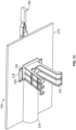
- the couplings of the present disclosure have thus far been described as "radial" couplings used in connection with coupling radial end faces of ring segments for use in tunnel building applications, in other versions, the same couplings could be used to couple other prefabricated or pre-cast building materials.
- the couplings could be used to couple adjacently positioned side faces of vertically arranged pre-cast concrete wall sections for retaining walls or building foundations, or side faces of horizontally arranged pre-cast concrete slabs for floor or road construction, for example.
- Other applications are possible.
Landscapes
- Engineering & Computer Science (AREA)
- Architecture (AREA)
- Structural Engineering (AREA)
- Mining & Mineral Resources (AREA)
- Civil Engineering (AREA)
- Geology (AREA)
- General Life Sciences & Earth Sciences (AREA)
- Geochemistry & Mineralogy (AREA)
- Life Sciences & Earth Sciences (AREA)
- Physics & Mathematics (AREA)
- Electromagnetism (AREA)
- Manufacturing & Machinery (AREA)
- Chemical & Material Sciences (AREA)
- Ceramic Engineering (AREA)
- Mechanical Engineering (AREA)
- Lining And Supports For Tunnels (AREA)
- Joining Of Building Structures In Genera (AREA)
Applications Claiming Priority (1)
| Application Number | Priority Date | Filing Date | Title |
|---|---|---|---|
| US201962861942P | 2019-06-14 | 2019-06-14 |
Publications (3)
| Publication Number | Publication Date |
|---|---|
| EP3751094A2 EP3751094A2 (en) | 2020-12-16 |
| EP3751094A3 EP3751094A3 (en) | 2021-02-17 |
| EP3751094B1 true EP3751094B1 (en) | 2024-01-10 |
Family
ID=70617010
Family Applications (1)
| Application Number | Title | Priority Date | Filing Date |
|---|---|---|---|
| EP20173523.0A Active EP3751094B1 (en) | 2019-06-14 | 2020-05-07 | Couplings for coupling pre-cast construction segments together and pre-cast construction segments having such couplings |
Country Status (4)
| Country | Link |
|---|---|
| US (1) | US11447947B2 (enExample) |
| EP (1) | EP3751094B1 (enExample) |
| JP (1) | JP7478591B2 (enExample) |
| CN (2) | CN214836383U (enExample) |
Families Citing this family (4)
| Publication number | Priority date | Publication date | Assignee | Title |
|---|---|---|---|---|
| US11447947B2 (en) * | 2019-06-14 | 2022-09-20 | Optimas OE Solutions, LLC | Couplings for coupling pre-cast construction segments together and pre-cast construction segments having such couplings |
| USD997308S1 (en) * | 2020-10-27 | 2023-08-29 | Optimas Oe Solutions Llc | Coupling |
| USD976693S1 (en) * | 2020-12-16 | 2023-01-31 | Optimas Oe Solutions Llc | Coupling |
| CN115929352B (zh) * | 2023-01-06 | 2025-06-27 | 中国电建集团贵阳勘测设计研究院有限公司 | 一种装配式盾构管片 |
Citations (1)
| Publication number | Priority date | Publication date | Assignee | Title |
|---|---|---|---|---|
| US4397583A (en) * | 1977-08-16 | 1983-08-09 | Charcon Tunnels Limited | Tunnel linings |
Family Cites Families (59)
| Publication number | Priority date | Publication date | Assignee | Title |
|---|---|---|---|---|
| US3680277A (en) | 1970-07-16 | 1972-08-01 | Brooke Hamilton J | Arrangement for connecting concrete or clay bricks, blocks, panels, and slabs |
| US3722160A (en) | 1971-02-25 | 1973-03-27 | C Bentley | Deck structure and connector for demountable parking building, or the like |
| JPS4881320A (enExample) * | 1972-01-20 | 1973-10-31 | ||
| JPS5246637A (en) * | 1975-10-13 | 1977-04-13 | Japan National Railway | Connection device of segment in method of shield construction |
| USD253392S (en) | 1977-10-17 | 1979-11-13 | Eaton Corporation | Mounting bracket |
| USD264682S (en) | 1980-03-10 | 1982-06-01 | Van Doren David A | Rebar support and nailing block holder |
| US4830536A (en) | 1981-08-07 | 1989-05-16 | Commercial Shearing, Inc. | Method and apparatus for tunnel lining |
| US4515501A (en) | 1981-12-15 | 1985-05-07 | Fairclough Civil Engineering Limited | Tunnel linings |
| GB2139268B (en) | 1983-05-05 | 1986-01-02 | Charcon Tunnels Ltd | Actuate concrete segments for tunnel or shaft linings |
| USD315673S (en) | 1988-02-26 | 1991-03-26 | Paul Harold J | Fastener |
| GB2228957B (en) | 1989-03-08 | 1992-10-21 | Charcon Tunnels Ltd | Improvements in or relating to arcuate pre-cast concrete tunnel lining segments |
| JP2847143B2 (ja) * | 1989-08-03 | 1999-01-13 | 石川島建材工業株式会社 | 掘削穴の覆工用筒状壁体 |
| USD351123S (en) | 1993-04-29 | 1994-10-04 | Richard Graham | Locomotive brake maintenance lock-out clamp |
| JP3523918B2 (ja) * | 1994-10-31 | 2004-04-26 | 鉄建建設株式会社 | トンネルの型枠継手 |
| JPH08312295A (ja) * | 1995-05-19 | 1996-11-26 | Nippon Kokan Light Steel Kk | セグメント継手とセグメントの連結構造 |
| USD401211S (en) | 1996-09-04 | 1998-11-17 | Simpson Patrick F | Jack bracket |
| JP3025203B2 (ja) | 1996-11-06 | 2000-03-27 | 稔 山本 | コンクリートセグメント用連結具 |
| USD421897S (en) | 1997-02-21 | 2000-03-28 | Keel Manufacturing, Inc. | Ceiling panel hold down clip |
| US5876084A (en) | 1997-07-15 | 1999-03-02 | Prince Corporation | Panel mounting clip |
| USD420483S (en) | 1997-10-06 | 2000-02-08 | Flexlink Systems Ab | Chain-link to a conveyor |
| GB2333140B (en) | 1998-01-09 | 2002-03-27 | Tarmac Uk Ltd | Connection assembly |
| GB2333799A (en) | 1998-01-29 | 1999-08-04 | Buchan C V Ltd | Device for joining two members together |
| JP2000054795A (ja) | 1998-08-11 | 2000-02-22 | Ohbayashi Corp | セグメント |
| JP2001123793A (ja) | 1999-10-27 | 2001-05-08 | Kubota Corp | コンクリートセグメント用連結金具とその連結金具を備えたコンクリートセグメント |
| USD669135S1 (en) | 2000-10-06 | 2012-10-16 | Garfinkle Benjamin L | Sign system adaptor |
| GB0025264D0 (en) | 2000-10-14 | 2000-11-29 | Smith C R | Device for joining segments |
| US6648278B1 (en) | 2001-03-15 | 2003-11-18 | Automatic Fire Control, Incorporated | Offset hanger |
| US6953300B2 (en) | 2004-01-05 | 2005-10-11 | Ted Chen | Combining device for suspending object |
| JP2005194813A (ja) * | 2004-01-09 | 2005-07-21 | Kubota Corp | コンクリートセグメント用連結金具 |
| KR100970986B1 (ko) | 2005-06-08 | 2010-07-20 | 한국 티알더블류 자동차부품산업 주식회사 | 플라스틱 파스너 |
| US7677829B2 (en) | 2005-10-20 | 2010-03-16 | Poly-Tec Products, Inc. | Inserts and reusable holder therefor |
| KR100589877B1 (ko) | 2005-12-20 | 2006-06-19 | 주식회사 픽슨이앤씨 | 파형강판 구조물의 보강라이너 설치용 거푸집 |
| USD569071S1 (en) | 2006-05-03 | 2008-05-13 | Universal Building Products, Inc. | Flat anchor for tilt-up concrete slabs |
| USD563769S1 (en) | 2006-08-17 | 2008-03-11 | Avf Group Limited | Pivot component for a mounting bracket |
| FR2915539B1 (fr) | 2007-04-26 | 2009-07-24 | Attax Sarl | Systeme de fixation de deux pieces l'une sur l'autre |
| USD588445S1 (en) | 2007-11-29 | 2009-03-17 | Barsplice Products, Inc. | Coupler body for connecting concrete reinforcing bars |
| WO2009097355A2 (en) | 2008-01-28 | 2009-08-06 | Kruse Darin R | Apparatus and methods for underground structures and construction thereof |
| PL2354447T3 (pl) | 2010-01-29 | 2017-09-29 | Officine Maccaferri Italia S.R.L. | Sposób podpierania i wzmacniania wyrobiska za pomocą żebra |
| USD632544S1 (en) | 2010-03-08 | 2011-02-15 | Garcia Jr Robert James | Nitrous oxide bottle mount |
| USD663494S1 (en) | 2010-09-30 | 2012-07-10 | Ourpet's Company | Clip for producing pinch-induced behavioral response |
| EP2625384A1 (en) * | 2010-10-05 | 2013-08-14 | Bosworth Plastics Limited | Coupling device |
| USD647784S1 (en) | 2010-10-13 | 2011-11-01 | Mueller International, Llc | Conduit hanger |
| USD664822S1 (en) | 2010-11-30 | 2012-08-07 | Barry Kent Romine | Level support clamp |
| JP5714317B2 (ja) | 2010-12-24 | 2015-05-07 | 大和化成工業株式会社 | バネクリップ |
| USD658053S1 (en) | 2011-08-12 | 2012-04-24 | Douglas Okun | Conduit clamp |
| USD736060S1 (en) | 2011-12-22 | 2015-08-11 | Nifco Inc. | Fastener |
| USD675337S1 (en) | 2011-12-23 | 2013-01-29 | Eppendorf Ag | Pipette support |
| SG11201609674TA (en) | 2014-06-04 | 2016-12-29 | Maccaferri Italia S R L Off | Rib for supporting and consolidating an excavation and method for installing a structure to support and consolidate an excavation |
| BR112016028327B1 (pt) | 2014-06-04 | 2022-06-07 | Officine Maccaferri Italia S.R.L. | Dispositivo para conectar elementos estruturais de nervuras e estruturas reticulares, nervura para suportar e consolidar uma escavação e método para sua instalação |
| JP5865445B2 (ja) * | 2014-07-14 | 2016-02-17 | 植村 誠 | オープンシールド工法に使用するコンクリート函体 |
| JP1518019S (enExample) | 2014-08-05 | 2015-02-23 | ||
| USD793215S1 (en) | 2015-08-25 | 2017-08-01 | Hellermanntyton Corporation | Blind hole mount |
| CA2917771C (en) | 2016-01-18 | 2022-09-13 | Victor A. Breda | Pipe holder and support |
| USD823672S1 (en) | 2016-03-16 | 2018-07-24 | Clips Group Holding Ivs | Fastening clip for cables |
| USD815939S1 (en) | 2016-08-25 | 2018-04-24 | Hellermanntyton Corporation | Blind hole mount |
| SE541774C2 (en) | 2017-03-23 | 2019-12-10 | Jilken Leif | Modular pier and attachment system for modular pier |
| USD895775S1 (en) | 2018-11-28 | 2020-09-08 | Graco Minnesota Inc. | Clip |
| US11447947B2 (en) * | 2019-06-14 | 2022-09-20 | Optimas OE Solutions, LLC | Couplings for coupling pre-cast construction segments together and pre-cast construction segments having such couplings |
| USD930464S1 (en) * | 2019-06-14 | 2021-09-14 | Optimas Oe Solutions Llc | Coupling |
-
2020
- 2020-04-01 US US16/837,790 patent/US11447947B2/en active Active
- 2020-05-07 EP EP20173523.0A patent/EP3751094B1/en active Active
- 2020-05-14 CN CN202020807507.9U patent/CN214836383U/zh active Active
- 2020-05-14 CN CN202010407972.8A patent/CN112081604B/zh active Active
- 2020-05-26 JP JP2020091042A patent/JP7478591B2/ja active Active
Patent Citations (1)
| Publication number | Priority date | Publication date | Assignee | Title |
|---|---|---|---|---|
| US4397583A (en) * | 1977-08-16 | 1983-08-09 | Charcon Tunnels Limited | Tunnel linings |
Also Published As
| Publication number | Publication date |
|---|---|
| EP3751094A2 (en) | 2020-12-16 |
| US11447947B2 (en) | 2022-09-20 |
| EP3751094A3 (en) | 2021-02-17 |
| CN112081604A (zh) | 2020-12-15 |
| CN214836383U (zh) | 2021-11-23 |
| CN112081604B (zh) | 2025-08-29 |
| JP2020204251A (ja) | 2020-12-24 |
| JP7478591B2 (ja) | 2024-05-07 |
| US20200392723A1 (en) | 2020-12-17 |
Similar Documents
| Publication | Publication Date | Title |
|---|---|---|
| EP3751094B1 (en) | Couplings for coupling pre-cast construction segments together and pre-cast construction segments having such couplings | |
| CA1106197A (en) | Wall segments | |
| CA1217645A (en) | Cast concrete element for underground tubular structure | |
| EP1326004B1 (en) | Composite segment | |
| US4545701A (en) | Tunnel wall structure | |
| JP5772658B2 (ja) | ハット型鋼矢板およびハット型鋼矢板を用いた構造体 | |
| JP4276715B2 (ja) | 管の継手構造 | |
| US10151113B2 (en) | Rebar centralizer for use in a drilled shaft/bore hole | |
| JP6594193B2 (ja) | 鋼管の継手機構及び連結方法 | |
| TW201420844A (zh) | 樁的無焊接接頭 | |
| US20250207345A1 (en) | Foundation support systems, assemblies and methods including sleeve coupler and self-aligning shafts with torque transmitting profiled distal end edges | |
| JP7390924B2 (ja) | ライナープレートの連結方法及び締結金具 | |
| JP4040196B2 (ja) | 雌雄金具による継手構造およびそれを用いたコンクリート部材 | |
| CN212452613U (zh) | 一种桩体护角套及预制建筑结构 | |
| JPH08326484A (ja) | プレキャストコンクリート体の継手構造およびプレキャストコンクリート体 | |
| JP7281125B2 (ja) | Rcセグメントを含むプレキャスト部材の挿入型継手及びこれを備えるセrcグメントを含むプレキャスト部材 | |
| JP2002081297A (ja) | 鋼殻セグメント構造 | |
| JP7543162B2 (ja) | 鋼製土留パネル、該鋼製土留パネルを用いた土留構造物、及び該土留構造物の構築工法 | |
| JP3450910B2 (ja) | セグメント継手 | |
| JP2024157251A (ja) | Rcセグメントを含むプレキャスト部材のスライドロック型継手及びこれを備えるrcセグメントを含むプレキャスト部材 | |
| JP2005120661A (ja) | セグメント用継手構造 | |
| JP7079448B2 (ja) | H形鋼杭の継手構造 | |
| JP4306930B2 (ja) | セグメント用継手、該継ぎ手を備えるセグメント、セグメント連結方法及び該セグメント用継手に用いる連結部材 | |
| JP2005315048A (ja) | 支保工用セグメント継手圧入装置、支保工用セグメント組立装置、セグメント継手構造 | |
| JP3539698B2 (ja) | 水平フック継手をもつセグメント |
Legal Events
| Date | Code | Title | Description |
|---|---|---|---|
| PUAI | Public reference made under article 153(3) epc to a published international application that has entered the european phase |
Free format text: ORIGINAL CODE: 0009012 |
|
| STAA | Information on the status of an ep patent application or granted ep patent |
Free format text: STATUS: THE APPLICATION HAS BEEN PUBLISHED |
|
| AK | Designated contracting states |
Kind code of ref document: A2 Designated state(s): AL AT BE BG CH CY CZ DE DK EE ES FI FR GB GR HR HU IE IS IT LI LT LU LV MC MK MT NL NO PL PT RO RS SE SI SK SM TR |
|
| AX | Request for extension of the european patent |
Extension state: BA ME |
|
| PUAL | Search report despatched |
Free format text: ORIGINAL CODE: 0009013 |
|
| AK | Designated contracting states |
Kind code of ref document: A3 Designated state(s): AL AT BE BG CH CY CZ DE DK EE ES FI FR GB GR HR HU IE IS IT LI LT LU LV MC MK MT NL NO PL PT RO RS SE SI SK SM TR |
|
| AX | Request for extension of the european patent |
Extension state: BA ME |
|
| RIC1 | Information provided on ipc code assigned before grant |
Ipc: E21D 11/08 20060101AFI20210111BHEP Ipc: E04B 1/41 20060101ALI20210111BHEP |
|
| STAA | Information on the status of an ep patent application or granted ep patent |
Free format text: STATUS: REQUEST FOR EXAMINATION WAS MADE |
|
| 17P | Request for examination filed |
Effective date: 20210811 |
|
| RBV | Designated contracting states (corrected) |
Designated state(s): AL AT BE BG CH CY CZ DE DK EE ES FI FR GB GR HR HU IE IS IT LI LT LU LV MC MK MT NL NO PL PT RO RS SE SI SK SM TR |
|
| STAA | Information on the status of an ep patent application or granted ep patent |
Free format text: STATUS: EXAMINATION IS IN PROGRESS |
|
| 17Q | First examination report despatched |
Effective date: 20221007 |
|
| GRAP | Despatch of communication of intention to grant a patent |
Free format text: ORIGINAL CODE: EPIDOSNIGR1 |
|
| STAA | Information on the status of an ep patent application or granted ep patent |
Free format text: STATUS: GRANT OF PATENT IS INTENDED |
|
| INTG | Intention to grant announced |
Effective date: 20230911 |
|
| GRAS | Grant fee paid |
Free format text: ORIGINAL CODE: EPIDOSNIGR3 |
|
| GRAA | (expected) grant |
Free format text: ORIGINAL CODE: 0009210 |
|
| STAA | Information on the status of an ep patent application or granted ep patent |
Free format text: STATUS: THE PATENT HAS BEEN GRANTED |
|
| AK | Designated contracting states |
Kind code of ref document: B1 Designated state(s): AL AT BE BG CH CY CZ DE DK EE ES FI FR GB GR HR HU IE IS IT LI LT LU LV MC MK MT NL NO PL PT RO RS SE SI SK SM TR |
|
| REG | Reference to a national code |
Ref country code: GB Ref legal event code: FG4D |
|
| REG | Reference to a national code |
Ref country code: CH Ref legal event code: EP |
|
| REG | Reference to a national code |
Ref country code: DE Ref legal event code: R096 Ref document number: 602020024096 Country of ref document: DE |
|
| REG | Reference to a national code |
Ref country code: IE Ref legal event code: FG4D |
|
| REG | Reference to a national code |
Ref country code: LT Ref legal event code: MG9D |
|
| REG | Reference to a national code |
Ref country code: NL Ref legal event code: MP Effective date: 20240110 |
|
| REG | Reference to a national code |
Ref country code: AT Ref legal event code: MK05 Ref document number: 1649043 Country of ref document: AT Kind code of ref document: T Effective date: 20240110 |
|
| PG25 | Lapsed in a contracting state [announced via postgrant information from national office to epo] |
Ref country code: NL Free format text: LAPSE BECAUSE OF FAILURE TO SUBMIT A TRANSLATION OF THE DESCRIPTION OR TO PAY THE FEE WITHIN THE PRESCRIBED TIME-LIMIT Effective date: 20240110 |
|
| PG25 | Lapsed in a contracting state [announced via postgrant information from national office to epo] |
Ref country code: NL Free format text: LAPSE BECAUSE OF FAILURE TO SUBMIT A TRANSLATION OF THE DESCRIPTION OR TO PAY THE FEE WITHIN THE PRESCRIBED TIME-LIMIT Effective date: 20240110 |
|
| PG25 | Lapsed in a contracting state [announced via postgrant information from national office to epo] |
Ref country code: IS Free format text: LAPSE BECAUSE OF FAILURE TO SUBMIT A TRANSLATION OF THE DESCRIPTION OR TO PAY THE FEE WITHIN THE PRESCRIBED TIME-LIMIT Effective date: 20240510 |
|
| PG25 | Lapsed in a contracting state [announced via postgrant information from national office to epo] |
Ref country code: LT Free format text: LAPSE BECAUSE OF FAILURE TO SUBMIT A TRANSLATION OF THE DESCRIPTION OR TO PAY THE FEE WITHIN THE PRESCRIBED TIME-LIMIT Effective date: 20240110 |
|
| PG25 | Lapsed in a contracting state [announced via postgrant information from national office to epo] |
Ref country code: GR Free format text: LAPSE BECAUSE OF FAILURE TO SUBMIT A TRANSLATION OF THE DESCRIPTION OR TO PAY THE FEE WITHIN THE PRESCRIBED TIME-LIMIT Effective date: 20240411 |
|
| PG25 | Lapsed in a contracting state [announced via postgrant information from national office to epo] |
Ref country code: RS Free format text: LAPSE BECAUSE OF FAILURE TO SUBMIT A TRANSLATION OF THE DESCRIPTION OR TO PAY THE FEE WITHIN THE PRESCRIBED TIME-LIMIT Effective date: 20240410 Ref country code: HR Free format text: LAPSE BECAUSE OF FAILURE TO SUBMIT A TRANSLATION OF THE DESCRIPTION OR TO PAY THE FEE WITHIN THE PRESCRIBED TIME-LIMIT Effective date: 20240110 |
|
| PG25 | Lapsed in a contracting state [announced via postgrant information from national office to epo] |
Ref country code: ES Free format text: LAPSE BECAUSE OF FAILURE TO SUBMIT A TRANSLATION OF THE DESCRIPTION OR TO PAY THE FEE WITHIN THE PRESCRIBED TIME-LIMIT Effective date: 20240110 |
|
| PG25 | Lapsed in a contracting state [announced via postgrant information from national office to epo] |
Ref country code: AT Free format text: LAPSE BECAUSE OF FAILURE TO SUBMIT A TRANSLATION OF THE DESCRIPTION OR TO PAY THE FEE WITHIN THE PRESCRIBED TIME-LIMIT Effective date: 20240110 |
|
| PG25 | Lapsed in a contracting state [announced via postgrant information from national office to epo] |
Ref country code: RS Free format text: LAPSE BECAUSE OF FAILURE TO SUBMIT A TRANSLATION OF THE DESCRIPTION OR TO PAY THE FEE WITHIN THE PRESCRIBED TIME-LIMIT Effective date: 20240410 Ref country code: NO Free format text: LAPSE BECAUSE OF FAILURE TO SUBMIT A TRANSLATION OF THE DESCRIPTION OR TO PAY THE FEE WITHIN THE PRESCRIBED TIME-LIMIT Effective date: 20240410 Ref country code: LT Free format text: LAPSE BECAUSE OF FAILURE TO SUBMIT A TRANSLATION OF THE DESCRIPTION OR TO PAY THE FEE WITHIN THE PRESCRIBED TIME-LIMIT Effective date: 20240110 Ref country code: IS Free format text: LAPSE BECAUSE OF FAILURE TO SUBMIT A TRANSLATION OF THE DESCRIPTION OR TO PAY THE FEE WITHIN THE PRESCRIBED TIME-LIMIT Effective date: 20240510 Ref country code: HR Free format text: LAPSE BECAUSE OF FAILURE TO SUBMIT A TRANSLATION OF THE DESCRIPTION OR TO PAY THE FEE WITHIN THE PRESCRIBED TIME-LIMIT Effective date: 20240110 Ref country code: GR Free format text: LAPSE BECAUSE OF FAILURE TO SUBMIT A TRANSLATION OF THE DESCRIPTION OR TO PAY THE FEE WITHIN THE PRESCRIBED TIME-LIMIT Effective date: 20240411 Ref country code: ES Free format text: LAPSE BECAUSE OF FAILURE TO SUBMIT A TRANSLATION OF THE DESCRIPTION OR TO PAY THE FEE WITHIN THE PRESCRIBED TIME-LIMIT Effective date: 20240110 Ref country code: BG Free format text: LAPSE BECAUSE OF FAILURE TO SUBMIT A TRANSLATION OF THE DESCRIPTION OR TO PAY THE FEE WITHIN THE PRESCRIBED TIME-LIMIT Effective date: 20240110 Ref country code: AT Free format text: LAPSE BECAUSE OF FAILURE TO SUBMIT A TRANSLATION OF THE DESCRIPTION OR TO PAY THE FEE WITHIN THE PRESCRIBED TIME-LIMIT Effective date: 20240110 |
|
| PG25 | Lapsed in a contracting state [announced via postgrant information from national office to epo] |
Ref country code: PT Free format text: LAPSE BECAUSE OF FAILURE TO SUBMIT A TRANSLATION OF THE DESCRIPTION OR TO PAY THE FEE WITHIN THE PRESCRIBED TIME-LIMIT Effective date: 20240510 Ref country code: PL Free format text: LAPSE BECAUSE OF FAILURE TO SUBMIT A TRANSLATION OF THE DESCRIPTION OR TO PAY THE FEE WITHIN THE PRESCRIBED TIME-LIMIT Effective date: 20240110 |
|
| PG25 | Lapsed in a contracting state [announced via postgrant information from national office to epo] |
Ref country code: SE Free format text: LAPSE BECAUSE OF FAILURE TO SUBMIT A TRANSLATION OF THE DESCRIPTION OR TO PAY THE FEE WITHIN THE PRESCRIBED TIME-LIMIT Effective date: 20240110 Ref country code: PT Free format text: LAPSE BECAUSE OF FAILURE TO SUBMIT A TRANSLATION OF THE DESCRIPTION OR TO PAY THE FEE WITHIN THE PRESCRIBED TIME-LIMIT Effective date: 20240510 Ref country code: PL Free format text: LAPSE BECAUSE OF FAILURE TO SUBMIT A TRANSLATION OF THE DESCRIPTION OR TO PAY THE FEE WITHIN THE PRESCRIBED TIME-LIMIT Effective date: 20240110 Ref country code: LV Free format text: LAPSE BECAUSE OF FAILURE TO SUBMIT A TRANSLATION OF THE DESCRIPTION OR TO PAY THE FEE WITHIN THE PRESCRIBED TIME-LIMIT Effective date: 20240110 |
|
| PG25 | Lapsed in a contracting state [announced via postgrant information from national office to epo] |
Ref country code: DK Free format text: LAPSE BECAUSE OF FAILURE TO SUBMIT A TRANSLATION OF THE DESCRIPTION OR TO PAY THE FEE WITHIN THE PRESCRIBED TIME-LIMIT Effective date: 20240110 |
|
| REG | Reference to a national code |
Ref country code: DE Ref legal event code: R097 Ref document number: 602020024096 Country of ref document: DE |
|
| PG25 | Lapsed in a contracting state [announced via postgrant information from national office to epo] |
Ref country code: SM Free format text: LAPSE BECAUSE OF FAILURE TO SUBMIT A TRANSLATION OF THE DESCRIPTION OR TO PAY THE FEE WITHIN THE PRESCRIBED TIME-LIMIT Effective date: 20240110 |
|
| PG25 | Lapsed in a contracting state [announced via postgrant information from national office to epo] |
Ref country code: EE Free format text: LAPSE BECAUSE OF FAILURE TO SUBMIT A TRANSLATION OF THE DESCRIPTION OR TO PAY THE FEE WITHIN THE PRESCRIBED TIME-LIMIT Effective date: 20240110 Ref country code: CZ Free format text: LAPSE BECAUSE OF FAILURE TO SUBMIT A TRANSLATION OF THE DESCRIPTION OR TO PAY THE FEE WITHIN THE PRESCRIBED TIME-LIMIT Effective date: 20240110 |
|
| PG25 | Lapsed in a contracting state [announced via postgrant information from national office to epo] |
Ref country code: SK Free format text: LAPSE BECAUSE OF FAILURE TO SUBMIT A TRANSLATION OF THE DESCRIPTION OR TO PAY THE FEE WITHIN THE PRESCRIBED TIME-LIMIT Effective date: 20240110 |
|
| PG25 | Lapsed in a contracting state [announced via postgrant information from national office to epo] |
Ref country code: SM Free format text: LAPSE BECAUSE OF FAILURE TO SUBMIT A TRANSLATION OF THE DESCRIPTION OR TO PAY THE FEE WITHIN THE PRESCRIBED TIME-LIMIT Effective date: 20240110 Ref country code: SK Free format text: LAPSE BECAUSE OF FAILURE TO SUBMIT A TRANSLATION OF THE DESCRIPTION OR TO PAY THE FEE WITHIN THE PRESCRIBED TIME-LIMIT Effective date: 20240110 Ref country code: RO Free format text: LAPSE BECAUSE OF FAILURE TO SUBMIT A TRANSLATION OF THE DESCRIPTION OR TO PAY THE FEE WITHIN THE PRESCRIBED TIME-LIMIT Effective date: 20240110 Ref country code: EE Free format text: LAPSE BECAUSE OF FAILURE TO SUBMIT A TRANSLATION OF THE DESCRIPTION OR TO PAY THE FEE WITHIN THE PRESCRIBED TIME-LIMIT Effective date: 20240110 Ref country code: DK Free format text: LAPSE BECAUSE OF FAILURE TO SUBMIT A TRANSLATION OF THE DESCRIPTION OR TO PAY THE FEE WITHIN THE PRESCRIBED TIME-LIMIT Effective date: 20240110 Ref country code: CZ Free format text: LAPSE BECAUSE OF FAILURE TO SUBMIT A TRANSLATION OF THE DESCRIPTION OR TO PAY THE FEE WITHIN THE PRESCRIBED TIME-LIMIT Effective date: 20240110 |
|
| PLBE | No opposition filed within time limit |
Free format text: ORIGINAL CODE: 0009261 |
|
| STAA | Information on the status of an ep patent application or granted ep patent |
Free format text: STATUS: NO OPPOSITION FILED WITHIN TIME LIMIT |
|
| 26N | No opposition filed |
Effective date: 20241011 |
|
| REG | Reference to a national code |
Ref country code: CH Ref legal event code: PL |
|
| PG25 | Lapsed in a contracting state [announced via postgrant information from national office to epo] |
Ref country code: MC Free format text: LAPSE BECAUSE OF FAILURE TO SUBMIT A TRANSLATION OF THE DESCRIPTION OR TO PAY THE FEE WITHIN THE PRESCRIBED TIME-LIMIT Effective date: 20240110 |
|
| PG25 | Lapsed in a contracting state [announced via postgrant information from national office to epo] |
Ref country code: LU Free format text: LAPSE BECAUSE OF NON-PAYMENT OF DUE FEES Effective date: 20240507 |
|
| PG25 | Lapsed in a contracting state [announced via postgrant information from national office to epo] |
Ref country code: MC Free format text: LAPSE BECAUSE OF FAILURE TO SUBMIT A TRANSLATION OF THE DESCRIPTION OR TO PAY THE FEE WITHIN THE PRESCRIBED TIME-LIMIT Effective date: 20240110 Ref country code: LU Free format text: LAPSE BECAUSE OF NON-PAYMENT OF DUE FEES Effective date: 20240507 Ref country code: CH Free format text: LAPSE BECAUSE OF NON-PAYMENT OF DUE FEES Effective date: 20240531 |
|
| REG | Reference to a national code |
Ref country code: BE Ref legal event code: MM Effective date: 20240531 |
|
| PG25 | Lapsed in a contracting state [announced via postgrant information from national office to epo] |
Ref country code: IE Free format text: LAPSE BECAUSE OF NON-PAYMENT OF DUE FEES Effective date: 20240507 |
|
| PG25 | Lapsed in a contracting state [announced via postgrant information from national office to epo] |
Ref country code: BE Free format text: LAPSE BECAUSE OF NON-PAYMENT OF DUE FEES Effective date: 20240531 Ref country code: SI Free format text: LAPSE BECAUSE OF FAILURE TO SUBMIT A TRANSLATION OF THE DESCRIPTION OR TO PAY THE FEE WITHIN THE PRESCRIBED TIME-LIMIT Effective date: 20240110 |
|
| PGFP | Annual fee paid to national office [announced via postgrant information from national office to epo] |
Ref country code: DE Payment date: 20250408 Year of fee payment: 6 |
|
| PGFP | Annual fee paid to national office [announced via postgrant information from national office to epo] |
Ref country code: GB Payment date: 20250410 Year of fee payment: 6 |
|
| PGFP | Annual fee paid to national office [announced via postgrant information from national office to epo] |
Ref country code: IT Payment date: 20250422 Year of fee payment: 6 |
|
| PGFP | Annual fee paid to national office [announced via postgrant information from national office to epo] |
Ref country code: FR Payment date: 20250409 Year of fee payment: 6 |
|
| REG | Reference to a national code |
Ref country code: DE Ref legal event code: R081 Ref document number: 602020024096 Country of ref document: DE Owner name: OPTIMAS OE SOLUTIONS, LLC, WOOD DALE, US Free format text: FORMER OWNER: OPTIMAS OE SOLUTIONS, LLC, GLENVIEW, IL 60026, US Ref country code: DE Ref legal event code: R081 Ref document number: 602020024096 Country of ref document: DE Owner name: OPTIMAS OE SOLUTIONS, SAS, FR Free format text: FORMER OWNER: OPTIMAS OE SOLUTIONS, LLC, GLENVIEW, IL 60026, US |
|
| PG25 | Lapsed in a contracting state [announced via postgrant information from national office to epo] |
Ref country code: CY Free format text: LAPSE BECAUSE OF FAILURE TO SUBMIT A TRANSLATION OF THE DESCRIPTION OR TO PAY THE FEE WITHIN THE PRESCRIBED TIME-LIMIT; INVALID AB INITIO Effective date: 20200507 |
|
| PG25 | Lapsed in a contracting state [announced via postgrant information from national office to epo] |
Ref country code: HU Free format text: LAPSE BECAUSE OF FAILURE TO SUBMIT A TRANSLATION OF THE DESCRIPTION OR TO PAY THE FEE WITHIN THE PRESCRIBED TIME-LIMIT; INVALID AB INITIO Effective date: 20200507 |
|
| REG | Reference to a national code |
Ref country code: GB Ref legal event code: 732E Free format text: REGISTERED BETWEEN 20250807 AND 20250813 |
|
| REG | Reference to a national code |
Ref country code: DE Ref legal event code: R081 Ref document number: 602020024096 Country of ref document: DE Owner name: OPTIMAS OE SOLUTIONS, SAS, FR Free format text: FORMER OWNER: OPTIMAS OE SOLUTIONS, LLC, WOOD DALE, IL, US |
|
| PG25 | Lapsed in a contracting state [announced via postgrant information from national office to epo] |
Ref country code: FI Free format text: LAPSE BECAUSE OF FAILURE TO SUBMIT A TRANSLATION OF THE DESCRIPTION OR TO PAY THE FEE WITHIN THE PRESCRIBED TIME-LIMIT Effective date: 20240110 |