EP3750840B1 - Türstatuserkennung mittels sensorfusion - Google Patents
Türstatuserkennung mittels sensorfusion Download PDFInfo
- Publication number
- EP3750840B1 EP3750840B1 EP20165503.2A EP20165503A EP3750840B1 EP 3750840 B1 EP3750840 B1 EP 3750840B1 EP 20165503 A EP20165503 A EP 20165503A EP 3750840 B1 EP3750840 B1 EP 3750840B1
- Authority
- EP
- European Patent Office
- Prior art keywords
- time period
- determining
- accelerations
- door
- axis
- Prior art date
- Legal status (The legal status is an assumption and is not a legal conclusion. Google has not performed a legal analysis and makes no representation as to the accuracy of the status listed.)
- Active
Links
Images



Classifications
-
- B—PERFORMING OPERATIONS; TRANSPORTING
- B66—HOISTING; LIFTING; HAULING
- B66B—ELEVATORS; ESCALATORS OR MOVING WALKWAYS
- B66B13/00—Doors, gates, or other apparatus controlling access to, or exit from, cages or lift well landings
- B66B13/02—Door or gate operation
- B66B13/14—Control systems or devices
-
- B—PERFORMING OPERATIONS; TRANSPORTING
- B66—HOISTING; LIFTING; HAULING
- B66B—ELEVATORS; ESCALATORS OR MOVING WALKWAYS
- B66B5/00—Applications of checking, fault-correcting, or safety devices in elevators
- B66B5/0006—Monitoring devices or performance analysers
- B66B5/0018—Devices monitoring the operating condition of the elevator system
-
- B—PERFORMING OPERATIONS; TRANSPORTING
- B66—HOISTING; LIFTING; HAULING
- B66B—ELEVATORS; ESCALATORS OR MOVING WALKWAYS
- B66B3/00—Applications of devices for indicating or signalling operating conditions of elevators
-
- B—PERFORMING OPERATIONS; TRANSPORTING
- B66—HOISTING; LIFTING; HAULING
- B66B—ELEVATORS; ESCALATORS OR MOVING WALKWAYS
- B66B5/00—Applications of checking, fault-correcting, or safety devices in elevators
- B66B5/0006—Monitoring devices or performance analysers
- B66B5/0018—Devices monitoring the operating condition of the elevator system
- B66B5/0025—Devices monitoring the operating condition of the elevator system for maintenance or repair
Definitions
- the embodiments herein relate to the field of conveyance systems, and specifically to a method and apparatus for monitoring a position of a conveyance apparatus of a conveyance system.
- Patent application No. CN 106 586 752 A discloses a system for acquiring opening and closing information of an elevator cage door.
- the system comprises an acceleration module which is connected with a single-chip MCU through data and is used for acquiring acceleration information of the cage door, completing acquisition of original data once within certain time and carrying out sum averaging on data of a set number of points to obtain a sum average serving as a sampling point.
- a method of monitoring a door of an elevator car within an elevator system including: detecting a first plurality of accelerations along an X-axis of the elevator system during a first time period; detecting a second plurality of accelerations along a Y-axis of the elevator system during the first time period; determining an absolute value of the first plurality of accelerations; determining an absolute value of the second plurality of accelerations; determining a first summation by combining the absolute value of the first plurality of accelerations with the absolute value of the second plurality of accelerations; and determining whether the door of the elevator car is in motion during the first time period by determining whether a maximum value of the first summation is greater than a threshold value.
- further embodiments of the method may include: adjusting the threshold value if the maximum value of the first summation is less than a selected value.
- Further embodiments of the method may include: detecting a third plurality of accelerations along an X-axis of the elevator system during a second time period; detecting a fourth plurality of accelerations along a Y-axis of the elevator system during the second time period; determining an absolute value of the third plurality of accelerations; determining an absolute value of the fourth plurality of accelerations; determining a second summation by combining the absolute value of the third plurality of accelerations with the absolute value of the fourth plurality of accelerations; and determining whether the door of the elevator car is in motion during the second time period by determining whether a maximum value of the second summation is greater than the threshold value.
- Further embodiments of the method may include: determining that the door of the elevator car is in motion during the first time period and the second time period; determining that the second time period occurs at greater than threshold time period after the first time period; and determining that the door was in a reversal motion during the first time period.
- Further embodiments of the method may include: determining that the maximum value of the first summation is greater than a threshold value; and determining that a door of the elevator car is in motion during the first time period when the maximum value of the first summation is greater than a threshold value.
- Further embodiments of the method may include: determining that the maximum value of the first summation is not greater than a threshold value; and determining that a door of the elevator car is not in motion during the first time period when the maximum value of the first summation is not greater than a threshold value.
- Further embodiments of the method may include that the X-axis is perpendicular to a Z-axis of the elevator system, the Z-axis being parallel to a direction of travel of the elevator car.
- Further embodiments of the method may include that the Y-axis is perpendicular to the X-axis and the Z-axis of the elevator system.
- a system for monitoring a door of an elevator car within an elevator system including: a sensor system including sensing apparatus; a processor; and a memory including computer-executable instructions that, when executed by the processor, cause the system to perform operations.
- the operations including: detecting a first plurality of accelerations along an X-axis of the elevator system during a first time period; detecting a second plurality of accelerations along a Y-axis of the elevator system during the first time period; determining an absolute value of the first plurality of accelerations; determining an absolute value of the second plurality of accelerations; determining a first summation of the absolute value of the first plurality of accelerations and the absolute value of the second plurality of accelerations; and determining whether the door of the elevator car is in motion during the first time period by determining whether a maximum value of the first summation is greater than a threshold value.
- a system for monitoring a door of an elevator car within an elevator system including: a controller; configured to carry out the following operations: detecting a first plurality of accelerations along an X-axis of the elevator system during a first time period; detecting a second plurality of accelerations along a Y-axis of the elevator system during the first time period; determining an absolute value of the first plurality of accelerations; determining an absolute value of the second plurality of accelerations; determining a first summation of the absolute value of the first plurality of accelerations and the absolute value of the second plurality of accelerations; and determining whether the door of the elevator car is in motion during the first time period by determining whether a maximum value of the first summation is greater than a threshold value.
- further embodiments of the system may include that the operations further include: adjusting the threshold value if the maximum value of the first summation is less than a selected value.
- Further embodiments of the system may include that the operations further include: detecting a third plurality of accelerations along an X-axis of the elevator system during a second time period; detecting a fourth plurality of accelerations along a Y-axis of the elevator system during the second time period; determining an absolute value of the third plurality of accelerations; determining an absolute value of the fourth plurality of accelerations; determining a second summation of the absolute value of the third plurality of accelerations and the absolute value of the fourth plurality of accelerations; and determining whether the door of the elevator car is in motion during the second time period by determining whether a maximum value of the second summation is greater than the threshold value.
- Further embodiments of the system may include that the operations further include: determining that the door of the elevator car is in motion during the first time period and the second time period; determining that the second time period occurs at greater than threshold time period after the first time period; and determining that the door was in a reversal motion during the first time period.
- Further embodiments of the system may include that the operations further include: determining that the door of the elevator car is in motion during the first time period and the second time period; determining that the second time period occurs at less than threshold time period after the first time period; determining that the door was in an opening motion during the first time period; and determining that the door was in a closing motion during the first time period.
- Further embodiments of the system may include that the operations further include: determining that the maximum value of the first summation is greater than a threshold value; and determining that a door of the elevator car is in motion during the first time period when the maximum value of the first summation is greater than a threshold value.
- Further embodiments of the system may include that the operations further include: determining that the maximum value of the first summation is not greater than a threshold value; and determining that a door of the elevator car is not in motion during the first time period when the maximum value of the first summation is not greater than a threshold value.
- Further embodiments of the system may include that the X-axis is perpendicular to a Z-axis of the elevator system, the Z-axis being parallel to a direction of travel of the elevator car.
- Further embodiments of the system may include that the Y-axis is perpendicular to the X-axis and the Z-axis of the elevator system.
- a non-transitory computer-readable medium may comprise instructions that, when executed by a processor, cause the processor to carry out the method outlined hereinabove.
- a non-transitory computer-readable medium comprising instructions that, when executed by a processor, cause the processor to carry out a method comprising:, detecting a first plurality of accelerations along an X-axis of the elevator system during a first time period; detecting a second plurality of accelerations along a Y-axis of the elevator system during the first time period; determining an absolute value of the first plurality of accelerations; determining an absolute value of the second plurality of accelerations; determining a first summation of the absolute value of the first plurality of accelerations and the absolute value of the second plurality of accelerations; and determining whether the door of the elevator car is in motion during the first time period by determining whether a maximum value of the first summation is
- inventions of the present disclosure include detecting accelerations of a door and determining movement of the door in response to the accelerations.
- FIG. 1 is a perspective view of an elevator system 101 including an elevator car 103, a counterweight 105, a tension member 107, a guide rail 109, a machine 111, a position reference system 113, and a controller 115.
- the elevator car 103 and counterweight 105 are connected to each other by the tension member 107.
- the tension member 107 may include or be configured as, for example, ropes, steel cables, and/or coated-steel belts.
- the counterweight 105 is configured to balance a load of the elevator car 103 and is configured to facilitate movement of the elevator car 103 concurrently and in an opposite direction with respect to the counterweight 105 within an elevator shaft 117 and along the guide rail 109.
- the tension member 107 engages the machine 111, which is part of an overhead structure of the elevator system 101.
- the machine 111 is configured to control movement between the elevator car 103 and the counterweight 105.
- the position reference system 113 may be mounted on a fixed part at the top of the elevator shaft 117, such as on a support or guide rail, and may be configured to provide position signals related to a position of the elevator car 103 within the elevator shaft 117. In other embodiments, the position reference system 113 may be directly mounted to a moving component of the machine 111, or may be located in other positions and/or configurations as known in the art.
- the position reference system 113 can be any device or mechanism for monitoring a position of an elevator car and/or counter weight, as known in the art.
- the position reference system 113 can be an encoder, sensor, or other system and can include velocity sensing, absolute position sensing, etc., as will be appreciated by those of skill in the art.
- the controller 115 is located, as shown, in a controller room 121 of the elevator shaft 117 and is configured to control the operation of the elevator system 101, and particularly the elevator car 103.
- the controller 115 may provide drive signals to the machine 111 to control the acceleration, deceleration, leveling, stopping, etc. of the elevator car 103.
- the controller 115 may also be configured to receive position signals from the position reference system 113 or any other desired position reference device.
- the elevator car 103 may stop at one or more landings 125 as controlled by the controller 115.
- the controller 115 can be located and/or configured in other locations or positions within the elevator system 101. In one embodiment, the controller may be located remotely or in the cloud.
- the machine 111 may include a motor or similar driving mechanism.
- the machine 111 is configured to include an electrically driven motor.
- the power supply for the motor may be any power source, including a power grid, which, in combination with other components, is supplied to the motor.
- the machine 111 may include a traction sheave that imparts force to tension member 107 to move the elevator car 103 within elevator shaft 117.
- FIG. 1 is merely a non-limiting example presented for illustrative and explanatory purposes.
- the system comprises a conveyance system that moves passengers between floors and/or along a single floor.
- conveyance systems may include escalators, people movers, etc.
- embodiments described herein are not limited to elevator systems, such as that shown in Figure 1 .
- embodiments disclosed herein may be applicable conveyance systems such as an elevator system 101 and a conveyance apparatus of the conveyance system such as an elevator car 103 of the elevator system 101.
- embodiments disclosed herein may be applicable conveyance systems such as an escalator system and a conveyance apparatus of the conveyance system such as a moving stair of the escalator system.
- the sensing apparatus 210 is configured to detect sensor data 202 of the elevator car 103 and transmit the sensor data 202 to a remote device 280.
- Sensor data 202 may include but is not limited to pressure data 314, vibratory signatures (i.e., vibrations over a period of time) or accelerations 312 and derivatives or integrals of accelerations 312 of the elevator car 103, such as, for example, distance, velocity, jerk, jounce, snap... etc.
- Sensor data 202 may also include light, sound, humidity, and temperature, or any other desired data parameter.
- the pressure data 314 may include atmospheric air pressure within the elevator shaft 117. It should be appreciated that, although particular systems are separately defined in the schematic block diagrams, each or any of the systems may be otherwise combined or separated via hardware and/or software.
- the sensing apparatus 210 may be a single sensor or may be multiple separate sensors that are interconnected.
- the sensing apparatus 210 is configured to transmit sensor data 202 that is raw and unprocessed to the controller 115 of the elevator system 101 for processing. In another embodiment, the sensing apparatus 210 is configured to process the sensor data 202 prior to transmitting the sensor data 202 to the controller 115 through a processing method, such as, for example, edge processing. In another embodiment, the sensing apparatus 210 is configured to transmit sensor data 202 that is raw and unprocessed to a remote system 280 for processing. In yet another embodiment, the sensing apparatus 210 is configured to process the sensor data 202 prior to transmitting the sensor data 202 to the remote device 280 through a processing method, such as, for example, edge processing.
- the processing of the sensor data 202 may reveal data, such as, for example, a number of elevator door openings/closings, elevator door time, vibrations, vibratory signatures, a number of elevator rides, elevator ride performance, elevator flight time, probable car position (e.g. elevation, floor number), releveling events, rollbacks, elevator car 103 x, y acceleration at a position: (i.e., rail topology), elevator car 103 x, y vibration signatures at a position: (i.e., rail topology), door performance at a landing number, nudging event, vandalism events, emergency stops, etc.
- data such as, for example, a number of elevator door openings/closings, elevator door time, vibrations, vibratory signatures, a number of elevator rides, elevator ride performance, elevator flight time, probable car position (e.g. elevation, floor number), releveling events, rollbacks, elevator car 103 x, y acceleration at a position: (i.e., rail topology),
- the remote device 280 may be a computing device, such as, for example, a desktop, a cloud based computer, and/or a cloud based artificial intelligence (AI) computing system.
- the remote device 280 may also be a mobile computing device that is typically carried by a person, such as, for example a smartphone, PDA, smartwatch, tablet, laptop, etc.
- the remote device 280 may also be two separate devices that are synced together, such as, for example, a cellular phone and a desktop computer synced over an internet connection.
- the remote device 280 may be an electronic controller including a processor 282 and an associated memory 284 comprising computer-executable instructions that, when executed by the processor 282, cause the processor 282 to perform various operations.
- the processor 282 may be, but is not limited to, a single-processor or multi-processor system of any of a wide array of possible architectures, including field programmable gate array (FPGA), central processing unit (CPU), application specific integrated circuits (ASIC), digital signal processor (DSP) or graphics processing unit (GPU) hardware arranged homogenously or heterogeneously.
- the memory 284 may be but is not limited to a random access memory (RAM), read only memory (ROM), or other electronic, optical, magnetic or any other computer readable medium.
- the sensing apparatus 210 is configured to transmit the sensor data 202 to the controller 115 or the remote device 280 via short-range wireless protocols 203 and/or long-range wireless protocols 204.
- Short-range wireless protocols 203 may include but are not limited to Bluetooth, Wi-Fi, HaLow (801.11ah), zWave, ZigBee, or Wireless M-Bus.
- the sensing apparatus 210 is configured to transmit the sensor data 202 to directly to the controller 115 or to a local gateway device 240 and the local gateway device 240 is configured to transmit the sensor data 202 to the remote device 280 through a network 250 or to the controller 115.
- the network 250 may be a computing network, such as, for example, a cloud computing network, cellular network, or any other computing network known to one of skill in the art.
- the sensing apparatus 210 is configured to transmit the sensor data 202 to the remote device 280 through a network 250.
- Long-range wireless protocols 204 may include but are not limited to cellular, satellite, LTE (NB-IoT, CAT M1), LoRa, Satellite, Ingenu, or SigFox.
- the sensing apparatus 210 may be configured to detect sensor data 202 including acceleration in any number of directions.
- the sensing apparatus may detect sensor data 202 including accelerations 312 along three axis, an X-axis, a Y-axis, and a Z-axis, as show in in FIG. 2 .
- the X-axis may be perpendicular to the doors 104 of the elevator car 103, as shown in FIG. 2 .
- the Y-axis may be parallel to the doors 104 of the elevator car 103, as shown in FIG. 2 .
- the Z-axis may be aligned vertically parallel with the elevator shaft 117, the direction of travel of the elevator car 103, and pull of gravity, as shown in FIG. 2 .
- the acceleration data 312 may reveal vibratory signatures generated along the X-axis, the Y-axis, and the Z-axis.
- the X-axis is perpendicular to the Y-axis and the Z-axis.
- the Y-axis is perpendicular to the X-axis and the Z-axis.
- the Z-axis is perpendicular to the X-axis and the Y-axis.
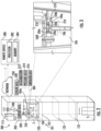
- FIG. 3 shows a possible installation location of the sensing apparatus 210 within the elevator system 101.
- the sensing apparatus 210 may include a magnet (not show) to removably attach to the elevator car 103.
- the sensing apparatus 210 may be installed on the door hanger 104a and/or the door 104 of the elevator system 101. It is understood that the sensing apparatus 210 may also be installed in other locations other than the door hanger 104a and the door 104 of the elevator system 101. It is also understood that multiple sensing apparatus 210 are illustrated in FIG. 3 to show various locations of the sensing apparatus 210 and the embodiments disclosed herein may include one or more sensing apparatus 210.
- the sensing apparatus 210 may be attached to a door header 104e of a door 104 of the elevator car 103. In another embodiment, the sensing apparatus 210 may be located on a door header 104e proximate a top portion 104f of the elevator car 103. In another embodiment, the sensing apparatus 210 is installed elsewhere on the elevator car 103, such as, for example, directly on the door 104.
- the sensing apparatus 201 may be located on the elevator car 103 in the selected areas 106, as shown in FIG. 3 .
- the doors 104 are operably connected to the door header 104e through a door hanger 104a located proximate a top portion 104b of the door 104.
- the door hanger 104a includes guide wheels 104c that allow the door 104 to slide open and close along a guide rail 104d on the door header 104e.
- the door hanger 104a is an easy to access area to attach the sensing apparatus 210 because the door hanger 104a is accessible when the elevator car 103 is at landing 125 and the elevator door 104 is open.
- the door hanger 104a also provides ample clearance for the sensing apparatus 210 during operation of the elevator car 103, such as, for example, door 104 opening and closing. Due to the mounting location of the sensing apparatus 210 on the door hanger 104a, the sensing apparatus 210 may detect open and close motions (i.e., acceleration) of the door 104 of the elevator car 103 and a door at the landing 125. Additionally mounting the sensing apparatus 210 on the hanger 104a allows for recording of a ride quality of the elevator car 103.
- FIG. 4 illustrates a block diagram of the sensing apparatus 210 of the sensing system of FIGs. 2 and 3 . It should be appreciated that, although particular systems are separately defined in the schematic block diagram of FIG. 4 , each or any of the systems may be otherwise combined or separated via hardware and/or software. As shown in FIG. 4 , the sensing apparatus 210 may include a controller 212, a plurality of sensors 217 in communication with the controller 212, a communication module 220 in communication with the controller 212, and a power source 222 electrically connected to the controller 212.
- the plurality of sensors 217 includes an inertial measurement unit (IMU) sensor 218 configured to detect sensor data 202 including accelerations 312 of the sensing apparatus 210 and the elevator car 103 when the sensing apparatus 210 is attached to the elevator car 103.
- the IMU sensor 218 may be a sensor, such as, for example, an accelerometer, a gyroscope, or a similar sensor known to one of skill in the art.
- the accelerations 312 detected by the IMU sensor 218 may include accelerations 312 as well as derivatives or integrals of accelerations, such as, for example, velocity, jerk, jounce, snap... etc.
- the IMU sensor 218 is in communication with the controller 212 of the sensing apparatus 210.
- the plurality of sensors 217 includes a pressure sensor 228 is configured to detect sensor data 202 including pressure data 314, such as, for example, atmospheric air pressure within the elevator shaft 117.
- the pressure sensor 228 may be a pressure altimeter or barometric altimeter in two non-limiting examples.
- the pressure sensor 228 is in communication with the controller 212.
- the plurality of sensors 217 may also include additional sensors including but not limited to a light sensor 226, a pressure sensor 228, a microphone 230, a humidity sensor 232, and a temperature sensor 234.
- the light sensor 226 is configured to detect sensor data 202 including light exposure.
- the light sensor 226 is in communication with the controller 212.
- the microphone 230 is configured to detect sensor data 202 including audible sound and sound levels.
- the microphone 230 is in communication with the controller 212.
- the humidity sensor 232 is configured to detect sensor data 202 including humidity levels.
- the humidity sensor 232 is in communication with the controller 212.
- the temperature sensor 234 is configured to detect sensor data 202 including temperature levels.
- the temperature sensor 234 is in communication with the controller 212.
- the controller 212 of the sensing apparatus 210 includes a processor 214 and an associated memory 216 comprising computer-executable instructions that, when executed by the processor 214, cause the processor 214 to perform various operations, such as, for example, edge pre-processing or processing the sensor data 202 collected by the IMU sensor 218, the light sensor 226, the pressure sensor 228, the microphone 230, the humidity sensor 232, and the temperature sensor 234.
- the controller 212 may process the accelerations 312 and/or the pressure data 314 in order to determine a probable location of the elevator car 103, discussed further below.
- the processor 214 may be but is not limited to a single-processor or multi-processor system of any of a wide array of possible architectures, including field programmable gate array (FPGA), central processing unit (CPU), application specific integrated circuits (ASIC), digital signal processor (DSP) or graphics processing unit (GPU) hardware arranged homogenously or heterogeneously.
- the memory 216 may be a storage device, such as, for example, a random access memory (RAM), read only memory (ROM), or other electronic, optical, magnetic or any other computer readable medium.
- the power source 222 of the sensing apparatus 210 is configured to store and supply electrical power to the sensing apparatus 210.
- the power source 222 may include an energy storage system, such as, for example, a battery system, capacitor, or other energy storage system known to one of skill in the art.
- the power source 222 may also generate electrical power for the sensing apparatus 210.
- the power source 222 may also include an energy generation or electricity harvesting system, such as, for example synchronous generator, induction generator, or other type of electrical generator known to one of skill in the art.
- the sensing apparatus 210 includes a communication module 220 configured to allow the controller 212 of the sensing apparatus 210 to communicate with the remote device 280 and/or controller 115 through at least one of short-range wireless protocols 203 and long-range wireless protocols 204.
- the communication module 220 may be configured to communicate with the remote device 280 using short-range wireless protocols 203, such as, for example, Bluetooth, Wi-Fi, HaLow (801.11ah), Wireless M-Bus, zWave, ZigBee, or other short-range wireless protocol known to one of skill in the art.
- the communication module 220 is configured to transmit the sensor data 202 to a local gateway device 240 and the local gateway device 240 is configured to transmit the sensor data 202 to a remote device 280 through a network 250, as described above.
- the communication module 220 may be configured to communicate with the remote device 280 using long-range wireless protocols 204, such as for example, cellular, LTE (NB-IoT, CAT M1), LoRa, Ingenu, SigFox, Satellite, or other long-range wireless protocol known to one of skill in the art.
- long-range wireless protocols 204 the communication module 220 is configured to transmit the sensor data 202 to a remote device 280 through a network 250.
- the short-range wireless protocol 203 is sub GHz Wireless M-Bus.
- the long-range wireless protocol is SigFox.
- the long-range wireless protocol is LTE NB-IoT or CAT M1 with 2G fallback.
- the sensing apparatus 210 includes a location determination module 330 configured to determine a location (i.e., position) of the elevator car 103 within the elevator shaft 117.
- the location of the elevator car 103 may be fixed locations along the elevator shaft 117, such as for example, the landings 125 of the elevator shaft 117.
- the locations may be equidistantly spaced apart along the elevator shaft 117 such as, for example, 5 meters or any other selected distance. Alternatively, the locations may be or intermittently spaced apart along the elevator shaft 117.
- the location determination module 330 may utilize various approaches to determine a location of the elevator car 103 within the elevator shaft 117.
- the location determination module 330 may be configured to determine a location of the elevator car 103 within the elevator shaft 117 using at least one of a pressure location determination module 310 and an acceleration location determination module 320.
- the acceleration location determination module 320 is configured to determine a distance traveled of the elevator car 103 within the elevator shaft 117 in response to the acceleration of the elevator car 103 detected along the Z axis.
- the sensing apparatus 210 may detect an acceleration along the Z axis shown at 322 and may integrate the acceleration to get a velocity of the elevator car 103 at 324.
- the sensing apparatus 210 may also integrate the velocity of the elevator car 103 to determine a distance traveled by the elevator car 103 within the elevator shaft 117 during the acceleration 312 detected at 322.
- the direction of travel of the elevator car 103 may also be determined in response to the acceleration 312 detected.
- the location determination module 330 may then determine the location of the elevator car 103 within the elevator shaft 117 in response to a starting location and a distance traveled away from that starting location.
- the starting location may be based upon tracking the past operation and/or movement of the elevator car 103.
- the pressure location determination module 310 is configured to detect an atmospheric air pressure within the elevator shaft 117 when the elevator car 103 is in motion and/or stationary using the pressure sensor 228.
- the pressure detected by the pressure sensor 228 may be associated with a location (e.g., height, elevation) within the elevator shaft 117 through either a look up table or a calculation of altitude using the barometric pressure change in two non-limiting embodiments.
- the direction of travel of the elevator car 103 may also be determined in response to the change in pressure detected via the pressure data 314.
- the pressure sensor 228 may need to periodically detect a baseline pressure to account for changes in atmospheric pressure due to local weather conditions. For example, this baseline pressure may need to be detected daily, hourly, or weekly in non-limiting embodiments.
- the baseline pressure may be detected whenever the elevator car 103 is stationary, or at certain intervals when the elevator car 103 is stationary and/or at a known location.
- the acceleration of the elevator car 103 may also need to be detected to know when the elevator car 103 is stationary and then when the elevator car 103 is stationary the sensing apparatus 210 may need to be offset to compensate the sensor drift and environment drift.
- the pressure location determination module 310 may be used to verify and/or modify a location of the elevator car 102 within the elevator shaft 117 determined by the acceleration location determination module 320.
- the acceleration location determination module 320 may be used to verify and/or modify a location of the elevator car 102 within the elevator shaft 117 determined by the pressure location determination module 310.
- the pressure location determination module 310 may be prompted to determine a location of the elevator car 103 within the elevator shaft 117 in response to an acceleration detected by the IMU sensor 218.
- FIG. 5 shows a flow chart of a method 500 of monitoring a door 104 of an elevator car 103 within an elevator system 101, in accordance with an embodiment of the disclosure.
- the method 500 may be performed by at least one of the sensing apparatus 210, the controller 115, and the remote device 280.
- FIG. 6 illustrates analysis of detected accelerations 312 of the elevator system 101 over time 601 within a chart 600.
- a first plurality of accelerations 602 is detected along an X-axis of the elevator system 101 during a first time period 610.
- X-axis is perpendicular to a Z-axis of the elevator system 101 and the Z-axis is parallel to a direction of travel of the elevator car 103.
- a second plurality of accelerations 604 is along a Y-axis of the elevator system 101 during the first time period 610.
- the Y-axis is perpendicular to the X-axis and the Z-axis of the elevator system 101.
- an absolute value of the first plurality of accelerations is determined.
- an absolute value of the second plurality of accelerations 604 is determined.
- the absolute value of the first plurality of accelerations 602 is combined with the absolute value of the second plurality of accelerations 604 and a first summation 630a determined.
- the first summation 630a of the absolute value of the first plurality of accelerations 602 and the absolute value of the second plurality of accelerations 604 may be visible on the chart 600 illustrated in FIG. 6 .
- MAX [ t 2 -t 1 ] is the maximum value during the first time period 610 of the first summation 630a of ( ABS ( acc x ( t ) )) + ( ABS ( acc y ( t ) )), ABS ( acc x ( t ) ) is the absolute value of the first plurality of accelerations 602 along the X-axis during the first time period 610, ABS ( acc y ( t ) ) is the absolute value of the second plurality of accelerations 604 along the Y-axis during the first time period 610.
- Equation i may generate a square function 650 at a value of one when the elevator door 104 is confirmed to be moving.
- X1 is a first variable and X2 is a second variable.
- the first variable is a base value, which allows detection of door movement for doors 104 with low vibrations or accelerations 312 (e.g. center opening doors).
- the threshold value needs to be adjusted, which may be accomplished by measuring the max acceleration values during door 104 movement and adjusting the threshold accordingly with the second variable.
- the first variable X1 may be equivalent to less than 300 mg.
- the second variable may be equivalent to about (20+7/30).
- the method 500 may further include: detecting a third plurality of accelerations 606 along an X-axis of the elevator system 101 during a second time period 620 and detecting a fourth plurality of accelerations 608 along a Y-axis of the elevator system 101 during the second time period 620.
- the method 500 may also include that an absolute value of the third plurality of accelerations 606 and an absolute value of the fourth plurality of accelerations 608 are determined.
- a second summation 630b may be determined.
- the second summation 630b is the summation of the absolute value of the third plurality of accelerations 606 and the absolute value of the fourth plurality of accelerations 608 may be visible on the chart 600 illustrated in FIG. 6 .
- It may then be determined whether the door 104 of the elevator car 103 is in motion during the second time period 620 by determining whether a maximum value 632b of the second summation 630b is greater than a threshold value 640, which may utilize equation iii IF MAX t 4 ⁇ t 3 ABS acc x t + ABS acc y t > Threshold Value THEN door movement TRUE
- MAX [ t 2 - t 1 ] is the maximum value 632b during the first time period 610 of the second summation 630b of ( ABS ( acc x ( t ) )) + ( ABS ( acc y ( t ) )), ABS ( acc x ( t ) ) is the absolute value of the third plurality of accelerations 606 along the X-axis during the second time period 620, ABS ( acc y ( t ) ) is the absolute value of the fourth plurality of accelerations 608 along the Y-axis during the second time period 620.
- the door 104 of the elevator car 103 is in motion during the first time period 610 and the second time period 620 and that the second time period 620 occurs at greater than threshold time period after the first time period 610 then it may be determined that the door was in a reversal motion during the first time period 610. For example, if the door motion is detected during the first time period 610 but then door motion is not detected moving until the next day during the second time period 620 then it may be determined that the door motion during the first time period 610 and the second time period 620 are not connected 9 (e.g., not an opening and closing pair)
- the door 104 of the elevator car 103 is in motion during the first time period 610 and the second time period 620 and that the second time period 620 occurs at less than a threshold time period after the first time period 610 then it may be determined that the door 103 was in an opening motion during the first time period 610 and the door 104 was in a closing motion during the second time period 620.
- the door motion is detected moving during the first time period 610 and then a short time later door motion is detected during the second time period then it may be determined that the motion during the first time period 610 and the second time period 620 are connected and the door motion during the first time period 610 may be an opening motion of the door 104 and the door motion during the second time period 620 may be a closing motion of the door 104 complimenting the opening motion.
Landscapes
- Engineering & Computer Science (AREA)
- Automation & Control Theory (AREA)
- Elevator Door Apparatuses (AREA)
- Maintenance And Inspection Apparatuses For Elevators (AREA)
Claims (14)
- Verfahren (500) zum Überwachen einer Tür (104) einer Aufzugskabine (103) innerhalb eines Aufzugssystems (101), wobei das Verfahren Folgendes umfasst:Erkennen einer ersten Vielzahl von Beschleunigungen (602) entlang einer X-Achse des Aufzugssystems (101) während eines ersten Zeitraums (610);Erkennen einer zweiten Vielzahl von Beschleunigungen (604) entlang einer Y-Achse des Aufzugssystems (101) während des ersten Zeitraums (610);Bestimmen eines Absolutwerts der ersten Vielzahl von Beschleunigungen (602);Bestimmen eines Absolutwerts der zweiten Vielzahl von Beschleunigungen (604);Bestimmen einer ersten Summation (630a) durch Kombinieren des Absolutwerts der ersten Vielzahl von Beschleunigungen (602) mit dem Absolutwert der zweiten Vielzahl von Beschleunigungen (604); undBestimmen, ob die Tür (104) der Aufzugskabine (103) während des ersten Zeitraums (610) in Bewegung ist, indem bestimmt wird, ob ein Maximalwert (632a) der ersten Summation (630a) größer als ein Schwellenwert (640) ist.
- Verfahren (500) nach Anspruch 1, ferner Folgendes umfassend: Einstellen des Schwellenwerts (640), wenn der Maximalwert (632a) der ersten Summation (630a) kleiner als ein ausgewählter Wert ist.
- Verfahren (500) nach Anspruch 1 oder 2, ferner Folgendes umfassend:Erkennen einer dritten Vielzahl von Beschleunigungen (606) entlang einer X-Achse des Aufzugssystems (101) während eines zweiten Zeitraums (620);Erkennen einer vierten Vielzahl von Beschleunigungen (608) entlang einer Y-Achse des Aufzugssystems (101) während des zweiten Zeitraums (620);Bestimmen eines Absolutwerts der dritten Vielzahl von Beschleunigungen (606);Bestimmen eines Absolutwerts der vierten Vielzahl von Beschleunigungen (608);Bestimmen einer zweiten Summation (630b) durch Kombinieren des Absolutwerts der dritten Vielzahl von Beschleunigungen (606) mit dem Absolutwert der vierten Vielzahl von Beschleunigungen (608); undBestimmen, ob die Tür (104) der Aufzugskabine (103) während des zweiten Zeitraums (620) in Bewegung ist, indem bestimmt wird, ob ein Maximalwert (632b) der zweiten Summation (630b) größer als der Schwellenwert (640) ist.
- Verfahren (500) nach Anspruch 3, ferner Folgendes umfassend:Bestimmen, dass die Tür (104) der Aufzugskabine (103) während des ersten Zeitraums (610) und des zweiten Zeitraums (620) in Bewegung ist;Bestimmen, dass der zweite Zeitraum (620) bei einem größeren als dem Schwellenwert-Zeitraum nach dem ersten Zeitraum (640) auftritt; undBestimmen, dass sich die Tür (104) während des ersten Zeitraums (610) in einer Umkehrbewegung befand.
- Verfahren (500) nach Anspruch 3, ferner Folgendes umfassend:Bestimmen, dass die Tür (104) der Aufzugskabine (103) während des ersten Zeitraums (610) und des zweiten Zeitraums (620) in Bewegung ist;Bestimmen, dass der zweite Zeitraum (620) bei einem kleineren als dem Schwellenwert-Zeitraum nach dem ersten Zeitraum (610) auftritt;Bestimmen, dass sich die Tür (104) während des ersten Zeitraums (610) in einer Öffnungsbewegung befand; undBestimmen, dass sich die Tür (104) während des ersten Zeitraums (610) in einer Schließbewegung befand.
- Verfahren (500) nach einem der vorhergehenden Ansprüche, ferner Folgendes umfassend:Bestimmen, dass der Maximalwert (632a) der ersten Summation (630a) größer als ein Schwellenwert (640) ist; undBestimmen, dass eine Tür (104) der Aufzugskabine (103) während des ersten Zeitraums (610) in Bewegung ist, wenn der Maximalwert (632a) der ersten Summation (630a) größer als ein Schwellenwert (640) ist.
- Verfahren (500) nach einem der vorhergehenden Ansprüche, ferner Folgendes umfassend:Bestimmen, dass der Maximalwert (632a) der ersten Summation (630a) nicht größer als ein Schwellenwert (640) ist; undBestimmen, dass eine Tür (104) der Aufzugskabine (103) während des ersten Zeitraums nicht in Bewegung ist, wenn der Maximalwert (632a) der ersten Summation (630a) nicht größer als ein Schwellenwert (640) ist.
- Verfahren (500) nach einem der vorhergehenden Ansprüche, wobei die X-Achse senkrecht zu einer Z-Achse des Aufzugssystems (101) verläuft, wobei die Z-Achse parallel zu einer Fahrtrichtung der Aufzugskabine (103) verläuft,
wobei gegebenenfalls die Y-Achse senkrecht zu der X-Achse und zu der Z-Achse des Aufzugssystems (101) verläuft. - System zum Überwachen einer Tür (104) einer Aufzugskabine (103) innerhalb eines Aufzugssystems (101), wobei das System Folgendes umfasst:ein Sensorsystem (200), das ein Sensorgerät (210) beinhaltet;einen Prozessor (282); undeinen Speicher (284), der computerausführbare Anweisungen umfasst;wobei die computerausführbaren Anweisungen, wenn sie durch den Prozessor (282) ausgeführt werden, das System veranlassen, Operationen durchzuführen, wobei die Operationen Folgendes umfassen:Erkennen einer ersten Vielzahl von Beschleunigungen (602) entlang einer X-Achse des Aufzugssystems (101) während eines ersten Zeitraums (610);Erkennen einer zweiten Vielzahl von Beschleunigungen (604) entlang einer Y-Achse des Aufzugssystems (101) während des ersten Zeitraums (610);Bestimmen eines Absolutwerts der ersten Vielzahl von Beschleunigungen (602);Bestimmen eines Absolutwerts der zweiten Vielzahl von Beschleunigungen (604);dadurch gekennzeichnet, dass die Operationen ferner Folgendes umfassen:Bestimmen einer ersten Summation (630a) durch Kombinieren des Absolutwerts der ersten Vielzahl von Beschleunigungen (602) mit dem Absolutwert der zweiten Vielzahl von Beschleunigungen (604); undBestimmen, ob die Tür (104) der Aufzugskabine (103) während des ersten Zeitraums (610) in Bewegung ist, indem bestimmt wird, ob ein Maximalwert (632a) der ersten Summation (630a) größer als ein Schwellenwert (640) ist.
- System nach Anspruch 9, wobei die Operationen ferner Folgendes umfassen:
Einstellen des Schwellenwerts (640), wenn der Maximalwert (632a) der ersten Summation (630a) kleiner als ein ausgewählter Wert ist. - System nach Anspruch 9 oder 10, wobei die Operationen ferner Folgendes umfassen:Erkennen einer dritten Vielzahl von Beschleunigungen (606) entlang einer X-Achse des Aufzugssystems (101) während eines zweiten Zeitraums (620);Erkennen einer vierten Vielzahl von Beschleunigungen (608) entlang einer Y-Achse des Aufzugssystems (101) während des zweiten Zeitraums (620);Bestimmen eines Absolutwerts der dritten Vielzahl von Beschleunigungen (606);Bestimmen eines Absolutwerts der vierten Vielzahl von Beschleunigungen (608);Bestimmen einer zweiten Summation (630b) durch Kombinieren des Absolutwerts der dritten Vielzahl von Beschleunigungen (606) mit dem Absolutwert der vierten Vielzahl von Beschleunigungen (608); undBestimmen, ob die Tür (104) der Aufzugskabine (103) während des zweiten Zeitraums (620) in Bewegung ist, indem bestimmt wird, ob ein Maximalwert (632b) der zweiten Summation (630b) größer als der Schwellenwert (640) ist.
- System nach Anspruch 11, wobei die Operationen ferner Folgendes umfassen:Bestimmen, dass die Tür (104) der Aufzugskabine (103) während des ersten Zeitraums (610) und des zweiten Zeitraums (620) in Bewegung ist;Bestimmen, dass der zweite Zeitraum (620) bei einem größeren als dem Schwellenwert-Zeitraum nach dem ersten Zeitraum (610) auftritt; undBestimmen, dass sich die Tür (104) während des ersten Zeitraums (610) in einer Umkehrbewegung befandund/oder wobei die Operationen ferner Folgendes umfassen:Bestimmen, dass die Tür (104) der Aufzugskabine (103) während des ersten Zeitraums (610) und des zweiten Zeitraums (620) in Bewegung ist;Bestimmen, dass der zweite Zeitraum (620) bei einem kleineren als dem Schwellenwert-Zeitraum nach dem ersten Zeitraum (610) auftritt;Bestimmen, dass sich die Tür (104) während des ersten Zeitraums (610) in einer Öffnungsbewegung befand; undBestimmen, dass sich die Tür (104) während des ersten Zeitraums (610) in einer Schließbewegung befand.
- System nach einem der Ansprüche 9 bis 12, wobei die Operationen ferner Folgendes umfassen:Bestimmen, dass der Maximalwert (632a) der ersten Summation (630a) größer als ein Schwellenwert (640) ist; und Bestimmen, dass eine Tür (104) der Aufzugskabine (103) während des ersten Zeitraums (610) in Bewegung ist, wenn der Maximalwert (632a) der ersten Summation (630a) größer als ein Schwellenwert (640) ist und/oderBestimmen, dass der Maximalwert (632a) der ersten Summation (630a) nicht größer als ein Schwellenwert (640) ist; und Bestimmen, dass eine Tür (104) der Aufzugskabine (103) während des ersten Zeitraums (610) nicht in Bewegung ist, wenn der Maximalwert (632a) der ersten Summation (630a) nicht größer als ein Schwellenwert (640) ist.
- System nach Anspruch 10, wobei die X-Achse senkrecht zu einer Z-Achse des Aufzugssystems (101) verläuft, wobei die Z-Achse parallel zu einer Fahrtrichtung der Aufzugskabine (103) verläuft,
wobei vorzugsweise die Y-Achse senkrecht zu der X-Achse und zu der Z-Achse des Aufzugssystems (101) verläuft.
Applications Claiming Priority (1)
| Application Number | Priority Date | Filing Date | Title |
|---|---|---|---|
| US16/410,021 US11542124B2 (en) | 2019-05-13 | 2019-05-13 | Sensor fusion door status detection |
Publications (2)
| Publication Number | Publication Date |
|---|---|
| EP3750840A1 EP3750840A1 (de) | 2020-12-16 |
| EP3750840B1 true EP3750840B1 (de) | 2023-12-06 |
Family
ID=69960571
Family Applications (1)
| Application Number | Title | Priority Date | Filing Date |
|---|---|---|---|
| EP20165503.2A Active EP3750840B1 (de) | 2019-05-13 | 2020-03-25 | Türstatuserkennung mittels sensorfusion |
Country Status (3)
| Country | Link |
|---|---|
| US (1) | US11542124B2 (de) |
| EP (1) | EP3750840B1 (de) |
| CN (1) | CN111924676B (de) |
Families Citing this family (2)
| Publication number | Priority date | Publication date | Assignee | Title |
|---|---|---|---|---|
| US11542124B2 (en) * | 2019-05-13 | 2023-01-03 | Otis Elevator Company | Sensor fusion door status detection |
| CN112520528B (zh) * | 2020-12-23 | 2021-06-22 | 江苏梯卫士网络科技有限公司 | 一种自动监测电梯故障检测系统及其检测方法 |
Family Cites Families (32)
| Publication number | Priority date | Publication date | Assignee | Title |
|---|---|---|---|---|
| FI20002390A0 (fi) | 2000-10-30 | 2000-10-30 | Kone Corp | Menetelmä hissin automaatioven kunnon valvomiseksi |
| JP2002274764A (ja) * | 2001-03-05 | 2002-09-25 | Otis Elevator Co | 階床呼出音登録方法および点字情報報知装置 |
| CN100542929C (zh) * | 2004-04-27 | 2009-09-23 | 三菱电机株式会社 | 电梯装置 |
| FI118532B (fi) | 2005-08-19 | 2007-12-14 | Kone Corp | Paikannusmenetelmä hissijärjestelmässä |
| DE202008002642U1 (de) * | 2008-02-25 | 2008-05-08 | Schneider Steuerungstechnik Gmbh | Steuerung für eine Aufzuganlage |
| CN102112388B (zh) * | 2008-06-13 | 2014-10-22 | 因温特奥股份公司 | 电梯设备和用于维护此类电梯设备的方法 |
| EP2319791A1 (de) * | 2009-11-10 | 2011-05-11 | Inventio AG | Aufzugsanlage |
| US8230980B2 (en) * | 2009-12-31 | 2012-07-31 | Inventio Ag | Method of operating elevators during emergency situations |
| KR101492358B1 (ko) * | 2011-01-26 | 2015-02-10 | 미쓰비시덴키 가부시키가이샤 | 엘리베이터의 행선층 등록 장치 |
| JP2014114111A (ja) * | 2012-12-10 | 2014-06-26 | Hitachi Ltd | 異常診断機能を有するエレベータ |
| KR101444187B1 (ko) * | 2013-05-29 | 2014-09-26 | 현대엘리베이터 주식회사 | 엘리베이터의 입력장치 |
| US11097923B2 (en) * | 2014-10-14 | 2021-08-24 | Xicore Inc. | Systems and methods for actively monitoring and controlling lift devices |
| DE102015211488A1 (de) * | 2015-06-22 | 2016-12-22 | Thyssenkrupp Ag | Sicherheitseinrichtung einer Aufzugsanlage |
| CN105668356B (zh) * | 2016-03-25 | 2018-03-30 | 江苏威尔曼科技有限公司 | 一种电梯厅外呼梯装置 |
| JP6506203B2 (ja) * | 2016-03-30 | 2019-04-24 | 株式会社日立ビルシステム | エレベーターの制御装置 |
| KR20170136804A (ko) * | 2016-06-02 | 2017-12-12 | 김택우 | 엘리베이터 조작반 |
| JP6233544B1 (ja) * | 2016-08-19 | 2017-11-22 | 三菱電機ビルテクノサービス株式会社 | エレベーターのかご内操作盤の外付け報知装置 |
| CN106586752B (zh) * | 2017-01-23 | 2019-01-22 | 大连奥远电子股份有限公司 | 一种采集电梯轿门开关信息的系统 |
| CN107337041B (zh) * | 2017-01-23 | 2019-04-09 | 大连奥远电子股份有限公司 | 一种采集电梯轿厢运动信息的系统 |
| CN110325467B (zh) * | 2017-02-28 | 2021-10-01 | 三菱电机株式会社 | 电梯的呼梯登记系统 |
| CN107010505A (zh) * | 2017-05-18 | 2017-08-04 | 厦门丰万达物联科技有限公司 | 基于加速度传感器的电梯轿厢门状态检测报警装置及方法 |
| CN110740959B (zh) * | 2017-06-14 | 2022-06-28 | 因温特奥股份公司 | 操作和/或显示面板、电梯轿厢系统和用于制造操作和/或显示面板的方法 |
| WO2019130589A1 (ja) * | 2017-12-28 | 2019-07-04 | ジャパンエレベーターサービスホールディングス株式会社 | エレベーター |
| CN108689271B (zh) * | 2018-06-15 | 2020-12-04 | 安徽中科福瑞科技有限公司 | 一种在线式电梯乘运质量检测系统及方法 |
| CN108609449B (zh) * | 2018-06-22 | 2023-09-15 | 福建省特种设备检验研究院 | 一种基于传感器的智能电梯检测仪及检测方法 |
| US11767194B2 (en) * | 2019-01-28 | 2023-09-26 | Otis Elevator Company | Elevator car and door motion monitoring |
| US11649136B2 (en) * | 2019-02-04 | 2023-05-16 | Otis Elevator Company | Conveyance apparatus location determination using probability |
| US12049383B2 (en) * | 2019-04-29 | 2024-07-30 | Otis Elevator Company | Elevator shaft distributed health level |
| US11542124B2 (en) * | 2019-05-13 | 2023-01-03 | Otis Elevator Company | Sensor fusion door status detection |
| JPWO2021075008A1 (de) * | 2019-10-16 | 2021-04-22 | ||
| JP7203999B2 (ja) * | 2019-10-16 | 2023-01-13 | ジャパンエレベーターサービスホールディングス株式会社 | エレベーター用防犯カメラ装置およびエレベーター |
| CN113184651B (zh) * | 2021-04-08 | 2022-09-13 | 浙江理工大学 | 一种电梯运行状态信号预处理和提取特征量方法 |
-
2019
- 2019-05-13 US US16/410,021 patent/US11542124B2/en active Active
-
2020
- 2020-03-25 EP EP20165503.2A patent/EP3750840B1/de active Active
- 2020-05-12 CN CN202010396491.1A patent/CN111924676B/zh active Active
Also Published As
| Publication number | Publication date |
|---|---|
| CN111924676A (zh) | 2020-11-13 |
| EP3750840A1 (de) | 2020-12-16 |
| CN111924676B (zh) | 2022-10-21 |
| US20200361749A1 (en) | 2020-11-19 |
| US11542124B2 (en) | 2023-01-03 |
Similar Documents
| Publication | Publication Date | Title |
|---|---|---|
| EP3733580B1 (de) | Sensorfusion von beschleunigungssensor- und luftdrucksensorinformationen zur schätzung der aufzugsstockwerksebene und -position | |
| EP3771680B1 (de) | Drucksensoralgorithmus zur erkennung von aufzugsstatusinformationen | |
| EP3798170B1 (de) | Luftdruck- und beschleunigungssensorbodenkorrektur durch aufzugsstatusinformationen | |
| US11472666B2 (en) | Elevator maintenance app matching mechanics position with faults detected | |
| EP3693311B1 (de) | Fördervorrichtungpositionsbestimmung mithilfe von wahrscheinlichkeit | |
| EP3733583B1 (de) | Verteiltes gesundheitsniveau eines aufzugsschachts | |
| EP4219375B1 (de) | Aufzugsschacht mit verteilter gesundheitsstufe mit mechanischer überwachung auf rückkopplungsbedingungsbasis | |
| EP3575258A1 (de) | Funksensor zur überwachung von förderanlagen | |
| EP3750840B1 (de) | Türstatuserkennung mittels sensorfusion | |
| EP3733581B1 (de) | Algorithmus zur erkennung einer aufzugsbewegungsrichtung | |
| EP3764296B1 (de) | Kundenverhaltensgesteuerte prädiktive wartung | |
| EP3981721B1 (de) | Verfahren zum überwachen einer fördervorrichtung innerhalb eines fördersystems |
Legal Events
| Date | Code | Title | Description |
|---|---|---|---|
| PUAI | Public reference made under article 153(3) epc to a published international application that has entered the european phase |
Free format text: ORIGINAL CODE: 0009012 |
|
| STAA | Information on the status of an ep patent application or granted ep patent |
Free format text: STATUS: THE APPLICATION HAS BEEN PUBLISHED |
|
| AK | Designated contracting states |
Kind code of ref document: A1 Designated state(s): AL AT BE BG CH CY CZ DE DK EE ES FI FR GB GR HR HU IE IS IT LI LT LU LV MC MK MT NL NO PL PT RO RS SE SI SK SM TR |
|
| AX | Request for extension of the european patent |
Extension state: BA ME |
|
| STAA | Information on the status of an ep patent application or granted ep patent |
Free format text: STATUS: REQUEST FOR EXAMINATION WAS MADE |
|
| 17P | Request for examination filed |
Effective date: 20210616 |
|
| RBV | Designated contracting states (corrected) |
Designated state(s): AL AT BE BG CH CY CZ DE DK EE ES FI FR GB GR HR HU IE IS IT LI LT LU LV MC MK MT NL NO PL PT RO RS SE SI SK SM TR |
|
| GRAP | Despatch of communication of intention to grant a patent |
Free format text: ORIGINAL CODE: EPIDOSNIGR1 |
|
| STAA | Information on the status of an ep patent application or granted ep patent |
Free format text: STATUS: GRANT OF PATENT IS INTENDED |
|
| INTG | Intention to grant announced |
Effective date: 20230620 |
|
| GRAS | Grant fee paid |
Free format text: ORIGINAL CODE: EPIDOSNIGR3 |
|
| GRAA | (expected) grant |
Free format text: ORIGINAL CODE: 0009210 |
|
| STAA | Information on the status of an ep patent application or granted ep patent |
Free format text: STATUS: THE PATENT HAS BEEN GRANTED |
|
| AK | Designated contracting states |
Kind code of ref document: B1 Designated state(s): AL AT BE BG CH CY CZ DE DK EE ES FI FR GB GR HR HU IE IS IT LI LT LU LV MC MK MT NL NO PL PT RO RS SE SI SK SM TR |
|
| REG | Reference to a national code |
Ref country code: GB Ref legal event code: FG4D |
|
| REG | Reference to a national code |
Ref country code: DE Ref legal event code: R096 Ref document number: 602020022163 Country of ref document: DE |
|
| REG | Reference to a national code |
Ref country code: CH Ref legal event code: EP |
|
| REG | Reference to a national code |
Ref country code: IE Ref legal event code: FG4D |
|
| REG | Reference to a national code |
Ref country code: LT Ref legal event code: MG9D |
|
| PG25 | Lapsed in a contracting state [announced via postgrant information from national office to epo] |
Ref country code: GR Free format text: LAPSE BECAUSE OF FAILURE TO SUBMIT A TRANSLATION OF THE DESCRIPTION OR TO PAY THE FEE WITHIN THE PRESCRIBED TIME-LIMIT Effective date: 20240307 |
|
| REG | Reference to a national code |
Ref country code: NL Ref legal event code: MP Effective date: 20231206 |
|
| PG25 | Lapsed in a contracting state [announced via postgrant information from national office to epo] |
Ref country code: LT Free format text: LAPSE BECAUSE OF FAILURE TO SUBMIT A TRANSLATION OF THE DESCRIPTION OR TO PAY THE FEE WITHIN THE PRESCRIBED TIME-LIMIT Effective date: 20231206 |
|
| PG25 | Lapsed in a contracting state [announced via postgrant information from national office to epo] |
Ref country code: ES Free format text: LAPSE BECAUSE OF FAILURE TO SUBMIT A TRANSLATION OF THE DESCRIPTION OR TO PAY THE FEE WITHIN THE PRESCRIBED TIME-LIMIT Effective date: 20231206 |
|
| PG25 | Lapsed in a contracting state [announced via postgrant information from national office to epo] |
Ref country code: LT Free format text: LAPSE BECAUSE OF FAILURE TO SUBMIT A TRANSLATION OF THE DESCRIPTION OR TO PAY THE FEE WITHIN THE PRESCRIBED TIME-LIMIT Effective date: 20231206 Ref country code: GR Free format text: LAPSE BECAUSE OF FAILURE TO SUBMIT A TRANSLATION OF THE DESCRIPTION OR TO PAY THE FEE WITHIN THE PRESCRIBED TIME-LIMIT Effective date: 20240307 Ref country code: ES Free format text: LAPSE BECAUSE OF FAILURE TO SUBMIT A TRANSLATION OF THE DESCRIPTION OR TO PAY THE FEE WITHIN THE PRESCRIBED TIME-LIMIT Effective date: 20231206 Ref country code: BG Free format text: LAPSE BECAUSE OF FAILURE TO SUBMIT A TRANSLATION OF THE DESCRIPTION OR TO PAY THE FEE WITHIN THE PRESCRIBED TIME-LIMIT Effective date: 20240306 |
|
| REG | Reference to a national code |
Ref country code: AT Ref legal event code: MK05 Ref document number: 1638239 Country of ref document: AT Kind code of ref document: T Effective date: 20231206 |
|
| PG25 | Lapsed in a contracting state [announced via postgrant information from national office to epo] |
Ref country code: NL Free format text: LAPSE BECAUSE OF FAILURE TO SUBMIT A TRANSLATION OF THE DESCRIPTION OR TO PAY THE FEE WITHIN THE PRESCRIBED TIME-LIMIT Effective date: 20231206 |
|
| PG25 | Lapsed in a contracting state [announced via postgrant information from national office to epo] |
Ref country code: SE Free format text: LAPSE BECAUSE OF FAILURE TO SUBMIT A TRANSLATION OF THE DESCRIPTION OR TO PAY THE FEE WITHIN THE PRESCRIBED TIME-LIMIT Effective date: 20231206 Ref country code: RS Free format text: LAPSE BECAUSE OF FAILURE TO SUBMIT A TRANSLATION OF THE DESCRIPTION OR TO PAY THE FEE WITHIN THE PRESCRIBED TIME-LIMIT Effective date: 20231206 Ref country code: NO Free format text: LAPSE BECAUSE OF FAILURE TO SUBMIT A TRANSLATION OF THE DESCRIPTION OR TO PAY THE FEE WITHIN THE PRESCRIBED TIME-LIMIT Effective date: 20240306 Ref country code: NL Free format text: LAPSE BECAUSE OF FAILURE TO SUBMIT A TRANSLATION OF THE DESCRIPTION OR TO PAY THE FEE WITHIN THE PRESCRIBED TIME-LIMIT Effective date: 20231206 Ref country code: LV Free format text: LAPSE BECAUSE OF FAILURE TO SUBMIT A TRANSLATION OF THE DESCRIPTION OR TO PAY THE FEE WITHIN THE PRESCRIBED TIME-LIMIT Effective date: 20231206 Ref country code: HR Free format text: LAPSE BECAUSE OF FAILURE TO SUBMIT A TRANSLATION OF THE DESCRIPTION OR TO PAY THE FEE WITHIN THE PRESCRIBED TIME-LIMIT Effective date: 20231206 |
|
| PG25 | Lapsed in a contracting state [announced via postgrant information from national office to epo] |
Ref country code: IS Free format text: LAPSE BECAUSE OF FAILURE TO SUBMIT A TRANSLATION OF THE DESCRIPTION OR TO PAY THE FEE WITHIN THE PRESCRIBED TIME-LIMIT Effective date: 20240406 |
|
| PG25 | Lapsed in a contracting state [announced via postgrant information from national office to epo] |
Ref country code: AT Free format text: LAPSE BECAUSE OF FAILURE TO SUBMIT A TRANSLATION OF THE DESCRIPTION OR TO PAY THE FEE WITHIN THE PRESCRIBED TIME-LIMIT Effective date: 20231206 Ref country code: CZ Free format text: LAPSE BECAUSE OF FAILURE TO SUBMIT A TRANSLATION OF THE DESCRIPTION OR TO PAY THE FEE WITHIN THE PRESCRIBED TIME-LIMIT Effective date: 20231206 |
|
| PG25 | Lapsed in a contracting state [announced via postgrant information from national office to epo] |
Ref country code: SK Free format text: LAPSE BECAUSE OF FAILURE TO SUBMIT A TRANSLATION OF THE DESCRIPTION OR TO PAY THE FEE WITHIN THE PRESCRIBED TIME-LIMIT Effective date: 20231206 |
|
| PG25 | Lapsed in a contracting state [announced via postgrant information from national office to epo] |
Ref country code: SM Free format text: LAPSE BECAUSE OF FAILURE TO SUBMIT A TRANSLATION OF THE DESCRIPTION OR TO PAY THE FEE WITHIN THE PRESCRIBED TIME-LIMIT Effective date: 20231206 Ref country code: SK Free format text: LAPSE BECAUSE OF FAILURE TO SUBMIT A TRANSLATION OF THE DESCRIPTION OR TO PAY THE FEE WITHIN THE PRESCRIBED TIME-LIMIT Effective date: 20231206 Ref country code: RO Free format text: LAPSE BECAUSE OF FAILURE TO SUBMIT A TRANSLATION OF THE DESCRIPTION OR TO PAY THE FEE WITHIN THE PRESCRIBED TIME-LIMIT Effective date: 20231206 Ref country code: IT Free format text: LAPSE BECAUSE OF FAILURE TO SUBMIT A TRANSLATION OF THE DESCRIPTION OR TO PAY THE FEE WITHIN THE PRESCRIBED TIME-LIMIT Effective date: 20231206 Ref country code: IS Free format text: LAPSE BECAUSE OF FAILURE TO SUBMIT A TRANSLATION OF THE DESCRIPTION OR TO PAY THE FEE WITHIN THE PRESCRIBED TIME-LIMIT Effective date: 20240406 Ref country code: EE Free format text: LAPSE BECAUSE OF FAILURE TO SUBMIT A TRANSLATION OF THE DESCRIPTION OR TO PAY THE FEE WITHIN THE PRESCRIBED TIME-LIMIT Effective date: 20231206 Ref country code: CZ Free format text: LAPSE BECAUSE OF FAILURE TO SUBMIT A TRANSLATION OF THE DESCRIPTION OR TO PAY THE FEE WITHIN THE PRESCRIBED TIME-LIMIT Effective date: 20231206 Ref country code: AT Free format text: LAPSE BECAUSE OF FAILURE TO SUBMIT A TRANSLATION OF THE DESCRIPTION OR TO PAY THE FEE WITHIN THE PRESCRIBED TIME-LIMIT Effective date: 20231206 |
|
| PG25 | Lapsed in a contracting state [announced via postgrant information from national office to epo] |
Ref country code: PT Free format text: LAPSE BECAUSE OF FAILURE TO SUBMIT A TRANSLATION OF THE DESCRIPTION OR TO PAY THE FEE WITHIN THE PRESCRIBED TIME-LIMIT Effective date: 20240408 Ref country code: PL Free format text: LAPSE BECAUSE OF FAILURE TO SUBMIT A TRANSLATION OF THE DESCRIPTION OR TO PAY THE FEE WITHIN THE PRESCRIBED TIME-LIMIT Effective date: 20231206 |
|
| PG25 | Lapsed in a contracting state [announced via postgrant information from national office to epo] |
Ref country code: PT Free format text: LAPSE BECAUSE OF FAILURE TO SUBMIT A TRANSLATION OF THE DESCRIPTION OR TO PAY THE FEE WITHIN THE PRESCRIBED TIME-LIMIT Effective date: 20240408 Ref country code: PL Free format text: LAPSE BECAUSE OF FAILURE TO SUBMIT A TRANSLATION OF THE DESCRIPTION OR TO PAY THE FEE WITHIN THE PRESCRIBED TIME-LIMIT Effective date: 20231206 |
|
| REG | Reference to a national code |
Ref country code: DE Ref legal event code: R097 Ref document number: 602020022163 Country of ref document: DE |
|
| PG25 | Lapsed in a contracting state [announced via postgrant information from national office to epo] |
Ref country code: DK Free format text: LAPSE BECAUSE OF FAILURE TO SUBMIT A TRANSLATION OF THE DESCRIPTION OR TO PAY THE FEE WITHIN THE PRESCRIBED TIME-LIMIT Effective date: 20231206 |
|
| PLBE | No opposition filed within time limit |
Free format text: ORIGINAL CODE: 0009261 |
|
| STAA | Information on the status of an ep patent application or granted ep patent |
Free format text: STATUS: NO OPPOSITION FILED WITHIN TIME LIMIT |
|
| PG25 | Lapsed in a contracting state [announced via postgrant information from national office to epo] |
Ref country code: SI Free format text: LAPSE BECAUSE OF FAILURE TO SUBMIT A TRANSLATION OF THE DESCRIPTION OR TO PAY THE FEE WITHIN THE PRESCRIBED TIME-LIMIT Effective date: 20231206 |
|
| PG25 | Lapsed in a contracting state [announced via postgrant information from national office to epo] |
Ref country code: SI Free format text: LAPSE BECAUSE OF FAILURE TO SUBMIT A TRANSLATION OF THE DESCRIPTION OR TO PAY THE FEE WITHIN THE PRESCRIBED TIME-LIMIT Effective date: 20231206 Ref country code: DK Free format text: LAPSE BECAUSE OF FAILURE TO SUBMIT A TRANSLATION OF THE DESCRIPTION OR TO PAY THE FEE WITHIN THE PRESCRIBED TIME-LIMIT Effective date: 20231206 |
|
| REG | Reference to a national code |
Ref country code: CH Ref legal event code: PL |
|
| 26N | No opposition filed |
Effective date: 20240909 |
|
| PG25 | Lapsed in a contracting state [announced via postgrant information from national office to epo] |
Ref country code: LU Free format text: LAPSE BECAUSE OF NON-PAYMENT OF DUE FEES Effective date: 20240325 |
|
| PG25 | Lapsed in a contracting state [announced via postgrant information from national office to epo] |
Ref country code: MC Free format text: LAPSE BECAUSE OF FAILURE TO SUBMIT A TRANSLATION OF THE DESCRIPTION OR TO PAY THE FEE WITHIN THE PRESCRIBED TIME-LIMIT Effective date: 20231206 |
|
| GBPC | Gb: european patent ceased through non-payment of renewal fee |
Effective date: 20240325 |
|
| PG25 | Lapsed in a contracting state [announced via postgrant information from national office to epo] |
Ref country code: MC Free format text: LAPSE BECAUSE OF FAILURE TO SUBMIT A TRANSLATION OF THE DESCRIPTION OR TO PAY THE FEE WITHIN THE PRESCRIBED TIME-LIMIT Effective date: 20231206 Ref country code: LU Free format text: LAPSE BECAUSE OF NON-PAYMENT OF DUE FEES Effective date: 20240325 |
|
| REG | Reference to a national code |
Ref country code: BE Ref legal event code: MM Effective date: 20240331 |
|
| PG25 | Lapsed in a contracting state [announced via postgrant information from national office to epo] |
Ref country code: BE Free format text: LAPSE BECAUSE OF NON-PAYMENT OF DUE FEES Effective date: 20240331 |
|
| PG25 | Lapsed in a contracting state [announced via postgrant information from national office to epo] |
Ref country code: GB Free format text: LAPSE BECAUSE OF NON-PAYMENT OF DUE FEES Effective date: 20240325 |
|
| PG25 | Lapsed in a contracting state [announced via postgrant information from national office to epo] |
Ref country code: IE Free format text: LAPSE BECAUSE OF NON-PAYMENT OF DUE FEES Effective date: 20240325 |
|
| PG25 | Lapsed in a contracting state [announced via postgrant information from national office to epo] |
Ref country code: IE Free format text: LAPSE BECAUSE OF NON-PAYMENT OF DUE FEES Effective date: 20240325 Ref country code: GB Free format text: LAPSE BECAUSE OF NON-PAYMENT OF DUE FEES Effective date: 20240325 Ref country code: BE Free format text: LAPSE BECAUSE OF NON-PAYMENT OF DUE FEES Effective date: 20240331 Ref country code: CH Free format text: LAPSE BECAUSE OF NON-PAYMENT OF DUE FEES Effective date: 20240331 |
|
| PG25 | Lapsed in a contracting state [announced via postgrant information from national office to epo] |
Ref country code: CY Free format text: LAPSE BECAUSE OF FAILURE TO SUBMIT A TRANSLATION OF THE DESCRIPTION OR TO PAY THE FEE WITHIN THE PRESCRIBED TIME-LIMIT; INVALID AB INITIO Effective date: 20200325 |
|
| PG25 | Lapsed in a contracting state [announced via postgrant information from national office to epo] |
Ref country code: HU Free format text: LAPSE BECAUSE OF FAILURE TO SUBMIT A TRANSLATION OF THE DESCRIPTION OR TO PAY THE FEE WITHIN THE PRESCRIBED TIME-LIMIT; INVALID AB INITIO Effective date: 20200325 |
|
| PG25 | Lapsed in a contracting state [announced via postgrant information from national office to epo] |
Ref country code: FI Free format text: LAPSE BECAUSE OF FAILURE TO SUBMIT A TRANSLATION OF THE DESCRIPTION OR TO PAY THE FEE WITHIN THE PRESCRIBED TIME-LIMIT Effective date: 20231207 |
|
| PG25 | Lapsed in a contracting state [announced via postgrant information from national office to epo] |
Ref country code: TR Free format text: LAPSE BECAUSE OF FAILURE TO SUBMIT A TRANSLATION OF THE DESCRIPTION OR TO PAY THE FEE WITHIN THE PRESCRIBED TIME-LIMIT Effective date: 20231206 |
|
| PGFP | Annual fee paid to national office [announced via postgrant information from national office to epo] |
Ref country code: DE Payment date: 20260219 Year of fee payment: 7 |
|
| PGFP | Annual fee paid to national office [announced via postgrant information from national office to epo] |
Ref country code: FR Payment date: 20260219 Year of fee payment: 7 |