EP3749564B1 - Von hand bewegbarer transportwagen - Google Patents
Von hand bewegbarer transportwagen Download PDFInfo
- Publication number
- EP3749564B1 EP3749564B1 EP19711240.2A EP19711240A EP3749564B1 EP 3749564 B1 EP3749564 B1 EP 3749564B1 EP 19711240 A EP19711240 A EP 19711240A EP 3749564 B1 EP3749564 B1 EP 3749564B1
- Authority
- EP
- European Patent Office
- Prior art keywords
- transport trolley
- transport
- receiving device
- weighing cell
- weighing
- Prior art date
- Legal status (The legal status is an assumption and is not a legal conclusion. Google has not performed a legal analysis and makes no representation as to the accuracy of the status listed.)
- Active
Links
Images


Classifications
-
- B—PERFORMING OPERATIONS; TRANSPORTING
- B62—LAND VEHICLES FOR TRAVELLING OTHERWISE THAN ON RAILS
- B62B—HAND-PROPELLED VEHICLES, e.g. HAND CARTS OR PERAMBULATORS; SLEDGES
- B62B3/00—Hand carts having more than one axis carrying transport wheels; Steering devices therefor; Equipment therefor
- B62B3/14—Hand carts having more than one axis carrying transport wheels; Steering devices therefor; Equipment therefor characterised by provisions for nesting or stacking, e.g. shopping trolleys
- B62B3/1476—Hand carts having more than one axis carrying transport wheels; Steering devices therefor; Equipment therefor characterised by provisions for nesting or stacking, e.g. shopping trolleys the main load support being a platform
-
- B—PERFORMING OPERATIONS; TRANSPORTING
- B62—LAND VEHICLES FOR TRAVELLING OTHERWISE THAN ON RAILS
- B62B—HAND-PROPELLED VEHICLES, e.g. HAND CARTS OR PERAMBULATORS; SLEDGES
- B62B3/00—Hand carts having more than one axis carrying transport wheels; Steering devices therefor; Equipment therefor
- B62B3/14—Hand carts having more than one axis carrying transport wheels; Steering devices therefor; Equipment therefor characterised by provisions for nesting or stacking, e.g. shopping trolleys
-
- B—PERFORMING OPERATIONS; TRANSPORTING
- B62—LAND VEHICLES FOR TRAVELLING OTHERWISE THAN ON RAILS
- B62B—HAND-PROPELLED VEHICLES, e.g. HAND CARTS OR PERAMBULATORS; SLEDGES
- B62B5/00—Accessories or details specially adapted for hand carts
-
- G—PHYSICS
- G01—MEASURING; TESTING
- G01G—WEIGHING
- G01G19/00—Weighing apparatus or methods adapted for special purposes not provided for in the preceding groups
- G01G19/08—Weighing apparatus or methods adapted for special purposes not provided for in the preceding groups for incorporation in vehicles
-
- G—PHYSICS
- G01—MEASURING; TESTING
- G01G—WEIGHING
- G01G19/00—Weighing apparatus or methods adapted for special purposes not provided for in the preceding groups
- G01G19/52—Weighing apparatus combined with other objects, e.g. furniture
-
- B—PERFORMING OPERATIONS; TRANSPORTING
- B62—LAND VEHICLES FOR TRAVELLING OTHERWISE THAN ON RAILS
- B62B—HAND-PROPELLED VEHICLES, e.g. HAND CARTS OR PERAMBULATORS; SLEDGES
- B62B2203/00—Grasping, holding, supporting the objects
- B62B2203/50—Grasping, holding, supporting the objects comprising weighing means
-
- H—ELECTRICITY
- H02—GENERATION; CONVERSION OR DISTRIBUTION OF ELECTRIC POWER
- H02J—ELECTRIC POWER NETWORKS; CIRCUIT ARRANGEMENTS OR SYSTEMS FOR SUPPLYING OR DISTRIBUTING ELECTRIC POWER; SYSTEMS FOR STORING ELECTRIC ENERGY
- H02J50/00—Circuit arrangements or systems for wireless supply or distribution of electric power
- H02J50/10—Circuit arrangements or systems for wireless supply or distribution of electric power using inductive coupling
Definitions
- the invention relates to a transport trolley that can be moved by hand, which can be stacked horizontally with the same transport trolley to save space and which is equipped with a chassis, with a sliding device and with at least one storage device intended for putting down or carrying objects, whereby in the stacked state there is the smallest possible distance between two transport trolleys, which creates a rear area and a front area in the stacked combination of the two transport trolleys, with the rear area being occupied only by the rear pushed-in transport trolley and the front area only being used by the transport trolley in front, with the at least one parking device having one equipped with at least one first and with at least one second load cell, associated with the at least one storage device in operative connection electronic weighing device, which is intended for determining the weight of the objects carried by the at least one storage device, and wherein at least the at least one first and the at least one second load cell is arranged on the at least one storage facility in such a way that when two identical transport vehicles are in the stacked state, the at least one second load cell of the inserted
- the document GB 2522291A discloses a shopping cart having scales.
- the document DE 196 43 122 A1 describes a mobile shopping cart that has, among other things, electronic scales, with the loading surface of the shopping cart forming the support surface for the scales. The total weight of the purchased goods is measured with the scales.
- the scale is plate-shaped and attached directly to the bottom of the loading area of the basket of the shopping cart.
- the document WO 2016/135142 relates to a system for identifying products placed in a shopping cart, this shopping cart also being equipped with scales designed to identify the products. Such shopping carts are now used in an Edeka supermarket.
- the solution to the problem is that when two identical transport carriages (1, 1') are stacked, the at least one first load cell (13) of the rear inserted transport carriage (1) is located within the rear area (15) and that conversely the at least a second load cell (14) of the preceding transport vehicle (1') is located within the front area (16), the at least one first load cell (13) starting from the at least one parking facility (6) downwards and the at least one second load cell (14 ) is directed upwards from the at least one storage device (6).
- the transport vehicle 1 has a chassis 2 and a sliding device 5 arranged at the rear.
- the chassis 2 carries a storage device 6, which is designed in the example as a loading platform 10 and can be parked on the items.
- the storage device 6 can be pivoted upwards and back again about a horizontal axis 9 located on the rear side 3 of the chassis 2 .
- the storage device 6 is supported on the chassis 2 at the front 4 of the chassis 2 .
- This construction is also known as the design of the chassis 2, which usually has a conical shape that allows the known stacking of such trolley 1.
- At the front end 8 of the storage device 6 is at least one second load cell 14 provided, which can extend upwards. In relation to a loading platform 10, this means that the at least one first load cell 13 can extend further down beyond the thickness of the loading platform 10 and the at least one second load cell 14 can extend beyond the thickness of the loading platform 10 upwards.
- the proposed here load cells 13, 14 belong to the prior art and z. B. offered by the German company Flintec.
- This offer includes u. Compressive force, tensile force, planar beam or single point load cells, which can be used optionally within the meaning of the present invention.
- the load cells 13, 14, also known by the term "weight sensors”, belong to at least one electronic weighing device 17 which, when connected to the at least one parking device 6, is operatively connected to the parking device 6 and which is used to determine the weight of the objects transported by the parking device 6 objects carried is determined.
- Each storage device 6 is assigned its own weighing device 17 .
- FIG. 2 also shows a side view of two transport carriages 1, 1' of the same design that have been pushed one inside the other to save space, ie stacked, see also 1 .
- the inserted trolley 1 is shown on the left.
- the preceding transport carriage 1' is located on the right in the drawing.
- Both trolleys 1, 1' are pushed into one another as far as possible, which can be seen from the dimensions A.
- a rear area 15 and a front area 16 are formed in this arrangement, shown hatched.
- the rear area 15 is only claimed by the inserted trolley 1 and the front area 16 only by the trolley 1' in front.
- the drawing shows that the at least one first and the at least one second load cell 13, 14 are arranged on the storage device 6 of the two transport carriages 1, 1' in such a way that the at least one first load cell 13 of the rear inserted transport carriage 1 is within the rear area 15 and the at least one second load cell 14 of the inserted transport carriage 1 ′ outside of the front area 16 .
- the rear area 15 and the front area 16 are each also referred to as "stack dead space".
- other components belonging to the weighing device 17 can also be attached to the transport carriage in such a way that they are also located in the rear and/or in the front area 15, 16 when two transport carriages 1, 1′ are stacked.
- Transport carriages 1 are usually equipped with swivel castors at the rear and/or at the front.
- Transport devices 1 are known which have only one swivel castor at the front, for example as a luggage trolley, and transport devices 1 are known which have two castors at the front.
- the transport trolley 1 is equipped with swivel castors at the rear and/or the front, and the rear area 15 and the front area 16 in the pushing direction of the transport trolley 1 are each shorter than the diameter of the interference circle of the swivel castors and/or shorter than one and a half times the diameter of the circles described by the running surfaces of the swivel castors.
- the diameter of the interference circle is equal to twice the swivel radius of a swivel castor. If the load cells 13, 14 are arranged in such short rear areas 15 and front areas 16, equipping a transport device 1 with a weighing device 17 does not have a disadvantageous effect on the size of known optimized stacking distances.
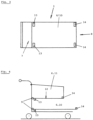
- FIG. 3 shows the in 1 described trolley 1 in plan view.
- two first load cells 13 and at the front end 8 two second load cells 14 are arranged geometrically regularly at the rear end 7 .
- the load cells 13, 14 form a rectangle. If only a first and a second weighing cell 13, 14 are required, it is proposed to arrange them either on the central longitudinal axis of the transport carriage 1 or on the corresponding transverse axis. More than four load cells 13, 14 can also be provided.
- the first load cells 13 can be arranged at a distance from the rear end 7 of the at least one storage device 6 and the second load cells 14 can be arranged at a distance from the front end 8 of the at least one storage device 6 .
- the horizontally greatest extent of the at least one first load cell 13 and/or the at least one second load cell 14 is greater than the stacking distance between two transport trolleys and the direction of the horizontally greatest extent of the load cells 13, 14 is at an angle to the sliding direction of the transport trolley.
- the direction of the greatest horizontal extension of the load cell is at right angles to the sliding direction of transport carriage 1.
- the stacking distance of two transport carriages in the sliding direction is in 2 shown as distance "A".
- the storage device 6 of a trolley 1 can also be designed in the form of a container 11, for example in the manner known from conventional shopping trolleys.
- the bottom 12 of the storage facility 6 designed in this way basically forms a loading platform 10 which is delimited by side walls.
- the at least one first load cell 13 and the at least a second load cell 14 are again arranged as has already been described above.
- a second storage device 6 with the corresponding load cells 13, 14 can also be provided below the storage device 6 arranged above.
- the bottom 12 of the storage device 6, as in the case of a loading platform 10 can be designed to be pivotable upwards about a horizontal axis 9.
- the complete storage device 6 designed as a container 11 is arranged on the chassis 2 so that it can be pivoted upwards and back again about a horizontal axis 9 and within a pivoting range that is also defined by stops. In both cases, the rear wall of the container 11 must also be pivotable in a known manner.
- Such designs of a storage facility 6 designed as a container 11 allow the floor 12 of such a storage facility 6 to be held in a horizontal position for use, since in general a horizontal arrangement of the floor 12 or a loading platform 10 makes the weighing process much easier in terms of an exact weight determination. This statement applies to all exemplary embodiments described here.
- other components that belong to the weighing device 17 or enable or support the function of the weighing device 17 can also be attached to the transport carriage 1 in such a way that, when two transport carriages 1, 1' are stacked, they are at least in the rear region 15 condition.
- figure 5 therefore shows a transport vehicle 1 in which, for example, the battery arrangement 18 intended for supplying energy to the weighing device 17 is located in the rear area 15 of the transport vehicle 1 . If energy is transmitted to the transport carriage 1 inductively, it is proposed that the at least one receiving coil 19 located on the transport carriage 1 should also be arranged in the rear area 15 . The same applies to other possible electronic control parts and the like. It proves to be advantageous if all the structural or functional parts just described are attached to the loading platform 10 within the rear area 15 and also use the space available below.
- the battery arrangement 18 in particular has a not inconsiderable weight, it makes sense to arrange the battery arrangement 18 very close to the horizontal axis 9 so that the weight of the battery arrangement 18 does not make it particularly difficult to stack the transport carriages 1, 1', 1''. The same applies to all the other parts mentioned above, which are shown as a package in the drawing.
- the invention gives the person skilled in the art free space for designing the storage device 6 .
- a frame unit or carrying unit can be pivoted about a horizontal axis 9 located on the rear side 3 of the chassis 2 .
- the load cells 13 , 14 are fastened to the frame unit and the loading platform 10 , which serves as a storage device 6 , is in turn fastened to the load cells.
- a storage device 6 can also be designed in such a way that it is suitable, for example, for hanging, ie for carrying, bags that are intended to hold the objects.
Landscapes
- Engineering & Computer Science (AREA)
- Chemical & Material Sciences (AREA)
- Combustion & Propulsion (AREA)
- Transportation (AREA)
- Mechanical Engineering (AREA)
- Physics & Mathematics (AREA)
- General Physics & Mathematics (AREA)
- Handcart (AREA)
Applications Claiming Priority (3)
| Application Number | Priority Date | Filing Date | Title |
|---|---|---|---|
| DE202018000613.0U DE202018000613U1 (de) | 2018-02-07 | 2018-02-07 | Von Hand bewegbarer Transportwagen mit einer Wiegeeinrichtung |
| DE202018000661.0U DE202018000661U1 (de) | 2018-02-09 | 2018-02-09 | Von Hand bewegbarer Transportwagen mit einer Wiegeeinrichtung |
| PCT/DE2019/000015 WO2019154449A1 (de) | 2018-02-07 | 2019-01-23 | Von hand bewegbarer transportwagen |
Publications (2)
| Publication Number | Publication Date |
|---|---|
| EP3749564A1 EP3749564A1 (de) | 2020-12-16 |
| EP3749564B1 true EP3749564B1 (de) | 2023-05-17 |
Family
ID=65801798
Family Applications (1)
| Application Number | Title | Priority Date | Filing Date |
|---|---|---|---|
| EP19711240.2A Active EP3749564B1 (de) | 2018-02-07 | 2019-01-23 | Von hand bewegbarer transportwagen |
Country Status (12)
| Country | Link |
|---|---|
| US (1) | US11440573B2 (pl) |
| EP (1) | EP3749564B1 (pl) |
| JP (1) | JP7245267B2 (pl) |
| KR (1) | KR102739380B1 (pl) |
| CN (1) | CN111954616B (pl) |
| AU (1) | AU2019217465B2 (pl) |
| CA (1) | CA3091520C (pl) |
| DE (1) | DE112019000702A5 (pl) |
| ES (1) | ES2952194T3 (pl) |
| PL (1) | PL3749564T3 (pl) |
| UA (1) | UA126771C2 (pl) |
| WO (1) | WO2019154449A1 (pl) |
Families Citing this family (5)
| Publication number | Priority date | Publication date | Assignee | Title |
|---|---|---|---|---|
| DE102020002894B4 (de) | 2020-05-14 | 2022-07-07 | Martin Eberlein | Durchgangsanlage |
| JP2022086977A (ja) * | 2020-11-30 | 2022-06-09 | 株式会社Retail AI | カート用重量測定装置およびカート |
| US11548544B2 (en) | 2021-03-23 | 2023-01-10 | Global Industrial Distribution Inc. | Stiffened nesting shopping cart |
| US11724728B2 (en) | 2021-03-23 | 2023-08-15 | Global Industrial Distribution Inc. | Reinforced nesting shopping cart |
| KR102932950B1 (ko) | 2023-01-04 | 2026-03-03 | 기검 | 제동장치가 구비된 카트 |
Family Cites Families (34)
| Publication number | Priority date | Publication date | Assignee | Title |
|---|---|---|---|---|
| US2644695A (en) * | 1948-10-14 | 1953-07-07 | William C Enders | Nesting type store service carrier |
| US2738201A (en) | 1951-10-29 | 1956-03-13 | George M Prescott | Platform truck |
| US2906542A (en) * | 1957-06-24 | 1959-09-29 | George E Hoedinghaus | Nesting market cart basket having a level bottom |
| US2992010A (en) | 1959-12-21 | 1961-07-11 | Raymond M Sides | Grocery carts |
| US3197224A (en) | 1963-06-11 | 1965-07-27 | Frieda E Kappen | Platform truck |
| US3789957A (en) * | 1972-04-05 | 1974-02-05 | J Close | Check out system |
| US3813111A (en) | 1972-08-16 | 1974-05-28 | Roblin Industries | Bumper construction for shopping cart |
| US4373611A (en) * | 1980-10-01 | 1983-02-15 | Frederick Roderick J | Conveyor to interfit with a loaded shopping cart and to move portions of the load, on demand of a checker, to the front of the cart, for removal, price scanning, and bagging, by the checker at a checkout stand |
| DE8214932U1 (de) | 1982-05-22 | 1982-07-22 | Rudolf Wanzl Kg, 8874 Leipheim | Transportwagen |
| FR2610256B2 (fr) * | 1986-10-03 | 1990-03-30 | Losego Martine | Amelioration d'un systeme de traction pour chariot a commissions et adaptation aux chariots a bagages |
| DE8714522U1 (de) | 1987-10-31 | 1988-05-05 | Rudolf Wanzl Kg, 8874 Leipheim | Von Hand bewegbarer Transportwagen, insbesondere Einkaufswagen |
| DE4032868A1 (de) * | 1989-10-21 | 1991-04-25 | Wanzl Entwicklung Gmbh | Von hand bewegbarer transportwagen |
| DE19643122A1 (de) | 1996-10-18 | 1998-04-23 | Kemal Demirli | Einkaufswagen oder Einkaufskorb zur Verwendung in Selbstbedienungsläden |
| JP3172905B2 (ja) * | 1997-03-04 | 2001-06-04 | 中日産業株式会社 | カート |
| FR2800345B1 (fr) * | 1999-10-27 | 2002-01-11 | Caddie Atel Reunis | Chariot emboitable adapte a recevoir des objets volumineux |
| US6488292B2 (en) | 2000-12-05 | 2002-12-03 | Unarco Industries, Inc. | Shopping cart having gate-guiding ledges |
| US6793223B2 (en) | 2002-05-03 | 2004-09-21 | Precision Wire Racks And Carts, Inc. | Convertible stocking cart |
| NL1027947C2 (nl) * | 2005-01-04 | 2006-01-09 | Scangineers B V | Mobiele boodschappen-verzamelinrichting. |
| EP1858743B1 (de) | 2005-06-25 | 2008-11-05 | Herbert Eberlein | Einkaufswagensortiment |
| DE202006019867U1 (de) | 2005-08-31 | 2007-06-06 | Ponto Gmbh | Von Hand bewegbarer Transportwagen |
| DE102005049029A1 (de) | 2005-10-11 | 2007-04-12 | Wanzl Metallwarenfabrik Gmbh | Transportcontainer |
| US7741808B2 (en) * | 2007-03-25 | 2010-06-22 | Media Cart Holdings, Inc. | Bi-directional charging/integrated power management unit |
| KR20110002143A (ko) * | 2009-07-01 | 2011-01-07 | (주)평화하이텍 | 로드셀을 지상에 노출토록 제작된 축중량 측정 저울 |
| GB0913990D0 (en) * | 2009-08-11 | 2009-09-16 | Connelly Sean R | Trolley |
| DE202011003780U1 (de) | 2011-03-10 | 2012-01-18 | Martin Eberlein | Einkaufswagen |
| US8733765B2 (en) | 2011-09-19 | 2014-05-27 | Disney Enterprises, Inc. | Airport divestment and luggage cart |
| US8827281B2 (en) * | 2012-02-02 | 2014-09-09 | Unarco Industries Llc | Tight nest shopping cart |
| DE202013001726U1 (de) | 2013-02-22 | 2013-08-22 | Martin Eberlein | Einrichtung zum Bereitstellen von Transportwagen |
| CN105307921B (zh) * | 2013-03-15 | 2019-03-19 | 碧美斯制造公司 | 购物车 |
| DE202013004429U1 (de) * | 2013-05-11 | 2014-05-15 | Martin Eberlein | Von Hand bewegbares Transportgerät |
| KR101424706B1 (ko) * | 2013-10-23 | 2014-08-01 | (주)메티스 | 자가 결제가 가능한 쇼핑카트 |
| KR101530361B1 (ko) * | 2013-12-04 | 2015-06-29 | (주)스케일트론 | 중량측정이 가능한 이동대차 |
| GB2522291A (en) * | 2014-01-20 | 2015-07-22 | Joseph Bentsur | Shopping cart and system |
| EP3262562B1 (en) | 2015-02-23 | 2022-10-19 | Pentland Firth Software GmbH | System and method for the identification of products in a shopping cart |
-
2019
- 2019-01-23 JP JP2020565514A patent/JP7245267B2/ja active Active
- 2019-01-23 WO PCT/DE2019/000015 patent/WO2019154449A1/de not_active Ceased
- 2019-01-23 ES ES19711240T patent/ES2952194T3/es active Active
- 2019-01-23 DE DE112019000702.5T patent/DE112019000702A5/de not_active Withdrawn
- 2019-01-23 US US16/965,277 patent/US11440573B2/en active Active
- 2019-01-23 UA UAA202005091A patent/UA126771C2/uk unknown
- 2019-01-23 EP EP19711240.2A patent/EP3749564B1/de active Active
- 2019-01-23 KR KR1020207024331A patent/KR102739380B1/ko active Active
- 2019-01-23 AU AU2019217465A patent/AU2019217465B2/en active Active
- 2019-01-23 PL PL19711240.2T patent/PL3749564T3/pl unknown
- 2019-01-23 CA CA3091520A patent/CA3091520C/en active Active
- 2019-01-23 CN CN201980011893.0A patent/CN111954616B/zh active Active
Also Published As
| Publication number | Publication date |
|---|---|
| CA3091520A1 (en) | 2019-08-15 |
| EP3749564A1 (de) | 2020-12-16 |
| KR102739380B1 (ko) | 2024-12-05 |
| PL3749564T3 (pl) | 2023-09-25 |
| CA3091520C (en) | 2022-11-22 |
| CN111954616B (zh) | 2024-09-17 |
| AU2019217465B2 (en) | 2024-08-15 |
| UA126771C2 (uk) | 2023-02-01 |
| KR20200116114A (ko) | 2020-10-08 |
| WO2019154449A1 (de) | 2019-08-15 |
| JP2021514329A (ja) | 2021-06-10 |
| US11440573B2 (en) | 2022-09-13 |
| ES2952194T3 (es) | 2023-10-30 |
| CN111954616A (zh) | 2020-11-17 |
| US20210070341A1 (en) | 2021-03-11 |
| JP7245267B2 (ja) | 2023-03-23 |
| AU2019217465A1 (en) | 2020-07-23 |
| DE112019000702A5 (de) | 2020-10-15 |
Similar Documents
| Publication | Publication Date | Title |
|---|---|---|
| DE102018132059B4 (de) | Einkaufswagen mit integrierter Gesamtwiegefunktion | |
| EP3749564A1 (de) | Von hand bewegbarer transportwagen | |
| DE202008013575U1 (de) | Transportsystem, insbesondere mit beweglichen Paletten | |
| DE19746933A1 (de) | Transportwagensystem | |
| EP2046621B1 (de) | Einkaufswagen | |
| DE202018000613U1 (de) | Von Hand bewegbarer Transportwagen mit einer Wiegeeinrichtung | |
| DE102008035914A1 (de) | Transportsystem, insbesondere mit beweglichen Paletten | |
| DE202018000661U1 (de) | Von Hand bewegbarer Transportwagen mit einer Wiegeeinrichtung | |
| DE202013004429U1 (de) | Von Hand bewegbares Transportgerät | |
| EP2683590B1 (de) | Einkaufswagen | |
| DE4337917C2 (de) | Stapelbarer Einkaufswagen | |
| EP2221590A2 (de) | Regallager und Transporteinrichtung eines solchen Regallagers | |
| DE19812119A1 (de) | Transportvorrichtung mit einem Einkaufskorb und einem Fahrgestell | |
| DE202013105333U1 (de) | Transporthubwagen zum Transport einer Last | |
| EP3115274A1 (de) | Rollwagen zum transport von stückgütern | |
| DE8331746U1 (de) | Stapelbarer einkaufswagen | |
| DE202023000478U1 (de) | Entladestation zum Entladen von Handkörben und/oder Rollkörben | |
| EP0620146A1 (de) | Einkaufswagen | |
| DE112017007686T5 (de) | Lösbarer Transportwagen | |
| EP1472130B1 (de) | Stapelbarer einkaufswagen | |
| EP3230150B1 (de) | Fahrbare rahmeneinheit | |
| DE29905790U1 (de) | Fahrzeugeigene Vorrichtung zum Be- und Entladen eines Transportfahrzeugs für mehrere im wesentlichen gleiche Behälter | |
| DE202021003323U1 (de) | Gerät zum Anheben eines Rollbehälters oder dergleichen sowie Kassentischanordnung | |
| DE102019000505A1 (de) | Von Hand bewegbarer Transportwagen zum Einkaufen von Ware | |
| DE202013004707U1 (de) | Mit gleichen Wagen stapelbarer Transportwagen |
Legal Events
| Date | Code | Title | Description |
|---|---|---|---|
| STAA | Information on the status of an ep patent application or granted ep patent |
Free format text: STATUS: UNKNOWN |
|
| STAA | Information on the status of an ep patent application or granted ep patent |
Free format text: STATUS: THE INTERNATIONAL PUBLICATION HAS BEEN MADE |
|
| PUAI | Public reference made under article 153(3) epc to a published international application that has entered the european phase |
Free format text: ORIGINAL CODE: 0009012 |
|
| STAA | Information on the status of an ep patent application or granted ep patent |
Free format text: STATUS: REQUEST FOR EXAMINATION WAS MADE |
|
| 17P | Request for examination filed |
Effective date: 20200731 |
|
| AK | Designated contracting states |
Kind code of ref document: A1 Designated state(s): AL AT BE BG CH CY CZ DE DK EE ES FI FR GB GR HR HU IE IS IT LI LT LU LV MC MK MT NL NO PL PT RO RS SE SI SK SM TR |
|
| AX | Request for extension of the european patent |
Extension state: BA ME |
|
| DAV | Request for validation of the european patent (deleted) | ||
| DAX | Request for extension of the european patent (deleted) | ||
| GRAP | Despatch of communication of intention to grant a patent |
Free format text: ORIGINAL CODE: EPIDOSNIGR1 |
|
| STAA | Information on the status of an ep patent application or granted ep patent |
Free format text: STATUS: GRANT OF PATENT IS INTENDED |
|
| INTG | Intention to grant announced |
Effective date: 20221026 |
|
| GRAS | Grant fee paid |
Free format text: ORIGINAL CODE: EPIDOSNIGR3 |
|
| GRAA | (expected) grant |
Free format text: ORIGINAL CODE: 0009210 |
|
| STAA | Information on the status of an ep patent application or granted ep patent |
Free format text: STATUS: THE PATENT HAS BEEN GRANTED |
|
| RAP3 | Party data changed (applicant data changed or rights of an application transferred) |
Owner name: EBERLEIN, MARTIN |
|
| RIN1 | Information on inventor provided before grant (corrected) |
Inventor name: EBERLEIN, MARTIN |
|
| AK | Designated contracting states |
Kind code of ref document: B1 Designated state(s): AT BE CH CZ DE ES FR GB IE IT LI NL PL |
|
| RBV | Designated contracting states (corrected) |
Designated state(s): AT BE CH CZ DE ES FR GB IE IT LI NL PL |
|
| REG | Reference to a national code |
Ref country code: GB Ref legal event code: FG4D Free format text: NOT ENGLISH |
|
| REG | Reference to a national code |
Ref country code: DE Ref legal event code: R096 Ref document number: 502019007734 Country of ref document: DE |
|
| REG | Reference to a national code |
Ref country code: CH Ref legal event code: EP |
|
| REG | Reference to a national code |
Ref country code: IE Ref legal event code: FG4D Free format text: LANGUAGE OF EP DOCUMENT: GERMAN |
|
| REG | Reference to a national code |
Ref country code: AT Ref legal event code: REF Ref document number: 1568287 Country of ref document: AT Kind code of ref document: T Effective date: 20230615 |
|
| REG | Reference to a national code |
Ref country code: NL Ref legal event code: FP |
|
| REG | Reference to a national code |
Ref country code: ES Ref legal event code: FG2A Ref document number: 2952194 Country of ref document: ES Kind code of ref document: T3 Effective date: 20231030 |
|
| REG | Reference to a national code |
Ref country code: DE Ref legal event code: R097 Ref document number: 502019007734 Country of ref document: DE |
|
| PLBE | No opposition filed within time limit |
Free format text: ORIGINAL CODE: 0009261 |
|
| STAA | Information on the status of an ep patent application or granted ep patent |
Free format text: STATUS: NO OPPOSITION FILED WITHIN TIME LIMIT |
|
| 26N | No opposition filed |
Effective date: 20240220 |
|
| PGFP | Annual fee paid to national office [announced via postgrant information from national office to epo] |
Ref country code: ES Payment date: 20250214 Year of fee payment: 7 |
|
| PGFP | Annual fee paid to national office [announced via postgrant information from national office to epo] |
Ref country code: PL Payment date: 20251230 Year of fee payment: 8 |
|
| REG | Reference to a national code |
Ref country code: CH Ref legal event code: U11 Free format text: ST27 STATUS EVENT CODE: U-0-0-U10-U11 (AS PROVIDED BY THE NATIONAL OFFICE) Effective date: 20260201 |
|
| PGFP | Annual fee paid to national office [announced via postgrant information from national office to epo] |
Ref country code: NL Payment date: 20260108 Year of fee payment: 8 |
|
| PGFP | Annual fee paid to national office [announced via postgrant information from national office to epo] |
Ref country code: GB Payment date: 20260113 Year of fee payment: 8 |
|
| PGFP | Annual fee paid to national office [announced via postgrant information from national office to epo] |
Ref country code: DE Payment date: 20260108 Year of fee payment: 8 Ref country code: IE Payment date: 20260108 Year of fee payment: 8 |
|
| PGFP | Annual fee paid to national office [announced via postgrant information from national office to epo] |
Ref country code: AT Payment date: 20260108 Year of fee payment: 8 |
|
| PGFP | Annual fee paid to national office [announced via postgrant information from national office to epo] |
Ref country code: BE Payment date: 20260108 Year of fee payment: 8 Ref country code: IT Payment date: 20260108 Year of fee payment: 8 |
|
| PGFP | Annual fee paid to national office [announced via postgrant information from national office to epo] |
Ref country code: FR Payment date: 20260113 Year of fee payment: 8 |
|
| PGFP | Annual fee paid to national office [announced via postgrant information from national office to epo] |
Ref country code: CH Payment date: 20260201 Year of fee payment: 8 Ref country code: CZ Payment date: 20260107 Year of fee payment: 8 |