EP3738904A2 - Domdeckel zum verschliessen einer öffnung eines behälters, behälter und fahrzeug damit - Google Patents
Domdeckel zum verschliessen einer öffnung eines behälters, behälter und fahrzeug damit Download PDFInfo
- Publication number
- EP3738904A2 EP3738904A2 EP20164620.5A EP20164620A EP3738904A2 EP 3738904 A2 EP3738904 A2 EP 3738904A2 EP 20164620 A EP20164620 A EP 20164620A EP 3738904 A2 EP3738904 A2 EP 3738904A2
- Authority
- EP
- European Patent Office
- Prior art keywords
- dome cover
- opening
- seal
- container
- dome
- Prior art date
- Legal status (The legal status is an assumption and is not a legal conclusion. Google has not performed a legal analysis and makes no representation as to the accuracy of the status listed.)
- Granted
Links
Images


Classifications
-
- B—PERFORMING OPERATIONS; TRANSPORTING
- B65—CONVEYING; PACKING; STORING; HANDLING THIN OR FILAMENTARY MATERIAL
- B65D—CONTAINERS FOR STORAGE OR TRANSPORT OF ARTICLES OR MATERIALS, e.g. BAGS, BARRELS, BOTTLES, BOXES, CANS, CARTONS, CRATES, DRUMS, JARS, TANKS, HOPPERS, FORWARDING CONTAINERS; ACCESSORIES, CLOSURES, OR FITTINGS THEREFOR; PACKAGING ELEMENTS; PACKAGES
- B65D90/00—Component parts, details or accessories for large containers
- B65D90/10—Manholes; Inspection openings; Covers therefor
-
- B—PERFORMING OPERATIONS; TRANSPORTING
- B60—VEHICLES IN GENERAL
- B60P—VEHICLES ADAPTED FOR LOAD TRANSPORTATION OR TO TRANSPORT, TO CARRY, OR TO COMPRISE SPECIAL LOADS OR OBJECTS
- B60P3/00—Vehicles adapted to transport, to carry or to comprise special loads or objects
- B60P3/22—Tank vehicles
- B60P3/224—Tank vehicles comprising auxiliary devices, e.g. for unloading or level indicating
- B60P3/226—Arrangements of access openings or covers therefor
-
- B—PERFORMING OPERATIONS; TRANSPORTING
- B65—CONVEYING; PACKING; STORING; HANDLING THIN OR FILAMENTARY MATERIAL
- B65D—CONTAINERS FOR STORAGE OR TRANSPORT OF ARTICLES OR MATERIALS, e.g. BAGS, BARRELS, BOTTLES, BOXES, CANS, CARTONS, CRATES, DRUMS, JARS, TANKS, HOPPERS, FORWARDING CONTAINERS; ACCESSORIES, CLOSURES, OR FITTINGS THEREFOR; PACKAGING ELEMENTS; PACKAGES
- B65D90/00—Component parts, details or accessories for large containers
- B65D90/54—Gates or closures
- B65D90/58—Gates or closures having closure members sliding in the plane of the opening
- B65D90/582—Gates or closures having closure members sliding in the plane of the opening having a rotational motion
- B65D90/585—Gates or closures having closure members sliding in the plane of the opening having a rotational motion around an axis perpendicular to the valve port
-
- B—PERFORMING OPERATIONS; TRANSPORTING
- B65—CONVEYING; PACKING; STORING; HANDLING THIN OR FILAMENTARY MATERIAL
- B65D—CONTAINERS FOR STORAGE OR TRANSPORT OF ARTICLES OR MATERIALS, e.g. BAGS, BARRELS, BOTTLES, BOXES, CANS, CARTONS, CRATES, DRUMS, JARS, TANKS, HOPPERS, FORWARDING CONTAINERS; ACCESSORIES, CLOSURES, OR FITTINGS THEREFOR; PACKAGING ELEMENTS; PACKAGES
- B65D90/00—Component parts, details or accessories for large containers
- B65D90/54—Gates or closures
- B65D90/62—Gates or closures having closure members movable out of the plane of the opening
- B65D90/623—Gates or closures having closure members movable out of the plane of the opening having a rotational motion
-
- B—PERFORMING OPERATIONS; TRANSPORTING
- B65—CONVEYING; PACKING; STORING; HANDLING THIN OR FILAMENTARY MATERIAL
- B65D—CONTAINERS FOR STORAGE OR TRANSPORT OF ARTICLES OR MATERIALS, e.g. BAGS, BARRELS, BOTTLES, BOXES, CANS, CARTONS, CRATES, DRUMS, JARS, TANKS, HOPPERS, FORWARDING CONTAINERS; ACCESSORIES, CLOSURES, OR FITTINGS THEREFOR; PACKAGING ELEMENTS; PACKAGES
- B65D2590/00—Component parts, details or accessories for large containers
- B65D2590/54—Gates or closures
- B65D2590/542—Gates or closures special sealing means or means for improving sealing
-
- B—PERFORMING OPERATIONS; TRANSPORTING
- B65—CONVEYING; PACKING; STORING; HANDLING THIN OR FILAMENTARY MATERIAL
- B65D—CONTAINERS FOR STORAGE OR TRANSPORT OF ARTICLES OR MATERIALS, e.g. BAGS, BARRELS, BOTTLES, BOXES, CANS, CARTONS, CRATES, DRUMS, JARS, TANKS, HOPPERS, FORWARDING CONTAINERS; ACCESSORIES, CLOSURES, OR FITTINGS THEREFOR; PACKAGING ELEMENTS; PACKAGES
- B65D2590/00—Component parts, details or accessories for large containers
- B65D2590/54—Gates or closures
- B65D2590/66—Operating devices therefor
- B65D2590/664—Operating devices therefor actuating mechanism other than manual, e.g. pneumatic, electropneumatic, hydraulic, electromagnetic
Definitions
- the invention relates to a dome cover for closing an opening of a container, the container being or being mountable in particular on a vehicle or chassis.
- Such a dome cover is known, for example, for closing filler necks or manholes of fillable containers, for example a silo or a tank, which can be mounted on a vehicle, also a rail vehicle or trailer or on another chassis.
- a lid or a locking device is also in the EP 1 917 162 B1 described.
- the described closing device is suitable for closing a filler neck of a container, whereby it can be pivoted when closing.
- the closing device has a seal which seals the filler neck in the closed state.
- ES 2 346 507 B1 describes a sealing system for a container with a pneumatic seal.
- the sealing system or the lid, which is part of it, can be moved parallel to the mouth of the container, that is, horizontally to the container.
- a pivotable design is advantageous if you want to open and close the container in a space-saving manner, especially in the direction above the container, since only a relatively narrow area above the container is required here and a filling process into the container is not restricted by an open lid.
- a hinged cover has the advantage that maintenance work on the cover, for example changing a seal, can be carried out more easily, since there is unhindered access to the underside of the cover.
- no mechanism is known which integrates both advantages together and thereby compensates for the respective disadvantages of the opening method with one mechanism.
- seals found in the prior art are not designed to enable the cover to be closed with as little friction as possible in order to protect the material of the seal.
- the reliable, quick and secure closing and sealing of a container with the aid of a dome lid can be improved by the features described in the present invention.
- the invention is based on the object of improving the closing and sealing mechanism in a dome cover of the type mentioned at the outset so that the container can be closed and sealed faster, more safely and more reliably.
- the dome cover has a mechanism for closing an opening of a container, whereby the upper part of the dome cover is attached to the opening of the container in a pivotable and / or foldable manner.
- the container can be a tank, a barrel, a container or some other type of vessel, which can be or can be mounted on a road and / or rail vehicle, a trailer, a car or another movable frame.
- the container can be suitable for the transport of goods, preferably for bulk goods, powdery or granular materials, but also liquids.
- the opening of the container can be a filler neck or a manhole or another opening in the container that can be used for filling, emptying or servicing the container.
- the opening can be attached to the top of the container, such as in the case of a tank that is filled from above. Otherwise, however, the opening can also be made on the side or on the underside of the container, either for emptying or to get better access to the container.
- the size of the opening can be different, For example, a smaller opening is required for filling or emptying small-sized materials than for maintaining the container, if a person has to fit through there. According to the invention, however, the opening of the container can always be closed with a lid, a hatch or some other movable part.
- the dome cover or the device which closes the opening of the container can, according to the invention, comprise a pivotable upper dome cover part which can be moved parallel to the surface of the container.
- the upper part of the dome cover is therefore arranged at the edge of the opening and can be rotated and / or displaced horizontally.
- the upper dome cover part can also be folded, that is to say pivotable about a horizontal axis, which means that the upper dome cover part can be placed vertically in comparison to the container surface.
- the upper part of the dome cover is attached to the edge of the opening and can be set up or opened from there.
- the lid can also be folded by more than 90 ° so that it is in an open position.
- a seal which seals the opening in the closed state, is preferably arranged in the outer edge region of the underside of the dome cover upper part.
- the seal can be arranged circumferentially on the dome cover edge, which means that the seal is arranged in the form of the opening or in the form of the dome cover edge circumference on the underside of the dome cover upper part at a small distance from the dome cover edge.
- the seal is arranged at the point at which the dome cover upper part and the edge of the opening touch, so where in the closed state the underside of the dome cover upper part rests on the container or the edge of its opening.
- the seal is at least partially embedded in a receiving groove on the underside of the dome cover upper part.
- the upper part of the dome cover has a receiving groove on its underside which is wide enough to accommodate at least part of the seal.
- the receiving groove preferably runs in the edge region of the dome cover upper part, wherein it preferably runs parallel to the circumference of the dome cover upper part and / or on the Place is placed where the underside of the dome cover top part touches the edge of the opening.
- the seal can be placed in the receiving groove, so that the seal partially protrudes from the underside of the dome cover upper part, but at least part of the seal disappears in the receiving groove of the dome cover upper part. The latter is the case when the receiving groove is less deep than the seal is high.
- the shape of the inner surface of the receiving groove can roughly correspond to the outer surface of the seal.
- the outer surface of the seal on the side facing the dome cover upper part, which is the side let into the dome cover upper part has the same shape as the receiving groove in which the seal is placed. This means that the seal rests as closely as possible on the upper part of the dome cover. Different outer surfaces for the seal are also possible here, which means that the receiving groove can also have different inner surfaces.
- the receiving groove and / or the seal are preferably at least partially rounded.
- the receiving groove has grooves or depressions in which protrusions, hooks or knobs, which are arranged on the outer surface of the seal, can engage or rest so that the seal is inserted State slipped more heavily and is better attached or attached.
- the seal can also be glued and / or clamped into the receiving groove for a better hold in the dome cover upper part.
- the seal of the dome cover particularly preferably has a hollow cross section.
- the seal can be concave on one side on the inner surface and convex on the opposite side.
- Particularly preferred is the outer surface on the side of the seal, which is embedded in the underside of the dome cover upper part, shaped so that the seal clings well to the shape of the receiving groove, so the seal is on the outside and on the inside in the direction of the receiving groove arched. This is especially the case when the seal is stretched or inflated.
- the seal is preferably curved inwards, that is to say towards the underside of the upper part of the dome cover.
- the surface can be on the outside and the inside of the seal also have different curvatures, up to different directions of curvature, for example if the surface of the seal is curved on the inside towards the dome cover upper part and on the outside towards the edge of the opening.
- the space in the interior of the seal is particularly preferably continuously connected.
- the seal is preferably resistant to positive and negative pressure when there is gas inside the seal.
- the seal is preferably connected to an air supply via a connection line, which is connected to a controller, by means of which the air supply can build up and reduce pressure in the seal.
- the pressure in the seal is reduced when the dome cover upper part is moved and pressure is built up when the dome cover upper part is in the closed state over the opening.
- the pressure can be built up and reduced, for example, in that a gas, in particular air, is pumped or blown into the seal or is let out or sucked out.
- the control of the gas supply can be controlled centrally by a control unit of the vehicle on which the container is mounted.
- the gas supply to the seal can also be controlled via a panel directly on the opening of the container or on the container itself, for example together with the movement of the upper part of the dome cover.
- the control automatically reduces the pressure in the seal before the upper part of the dome cover is moved into an open or folded-open state, so that it is ensured that the upper part of the dome cover is not moved in a state in which the seal could rub.
- the seal is preferably subjected to negative pressure via the control system before the upper part of the dome cover is opened and / or pivoted, so that the seal retracts into the receiving groove on the underside of the upper part of the dome cover.
- a cover for the seal nor a flange that protects the seal is necessary because the retraction of the seal into the receiving groove on the underside of the dome cover upper part reduces the friction during pivoting and / or Opening of the dome cover upper part is reduced or completely prevented.
- the seal retracts completely into the receiving groove on the underside of the dome cover upper part before the dome cover upper part is moved.
- the dome cover is preferably designed in such a way that the dome cover upper part can be set up or can be set up for maintenance purposes, the seal being checked and / or exchanged in the set up position of the dome cover upper part.
- the seal is designed or can be designed such that it can be easily removed when the dome cover upper part is in the erected state, for example when the seal can be removed from the dome cover upper part in a few simple steps. This is especially the case when the seal can be clamped in recesses in the receiving groove by means of protrusions on the outside of the surface, which, however, are easy to loosen, for example when the seal is compressed.
- the upper part of the dome cover can also be equipped with an overload protection device in the erected state, which swings it out when the pressure on the upper part of the dome cover accidentally gets in the way and otherwise the fastening of the upper part of the dome cover could be damaged in the unfolded state.
- an overload protection device in the erected state, which swings it out when the pressure on the upper part of the dome cover accidentally gets in the way and otherwise the fastening of the upper part of the dome cover could be damaged in the unfolded state.
- this can take place during loading if the dome cover upper part is inadvertently in the unfolded and not in the swiveled-open state.
- the dome cover has a swivel joint which is connected to a swivel arm via which the dome cover upper part is connected to the container, with an angular contact ball bearing, in particular a double-row, being formed in the swivel joint.
- the upper part of the dome cover can be pivoted laterally, i.e. horizontally to the container surface, via the swivel joint.
- Either the dome cover upper part can also be folded over this hinge, that is to say it can be set up vertically to the container surface, but the dome cover preferably also has a separate pivoting mechanism for vertical positioning of the upper part of the dome cover.
- an end stop is arranged on the pivoting mechanism for the vertical position, which prevents the upper part of the dome cover from being deflected too far.
- a sliding sleeve is usually used for the horizontal pivoting of the dome cover upper part instead of an angular contact ball bearing, as is preferred in the present invention.
- the angular ball bearing offers better loading capacity in the axial and radial directions.
- the swivel joint is attached to the container or the edge of the opening of the container and the other side is connected to the swivel arm, which is fastened to the upper part of the dome cover, and thereby connects the upper part of the dome cover to the container or to the edge of the opening of the container.
- the swivel joint preferably swivels the upper part of the dome cover out by at least 90 ° via a swivel arm.
- the swivel joint and the swivel arm hold the dome cover upper part freely floating, that is to say the dome cover upper part does not require a guide rail for the pivoting.
- the swivel arm of the dome cover is designed in such a way that it can hold the upper part of the dome cover free from the container surface when it is open.
- the swivel joint and / or the swivel arm of the dome cover particularly preferably have a pneumatic or electric drive.
- the pneumatic or electrical drive of the swivel joint or the swivel mechanism is preferably attached laterally on the outside of the edge of the opening, particularly preferably directly next to the swivel joint.
- the pivoting mechanism of the dome cover is preferably designed to be adjustable so that readjustment is possible when the seal is worn. If the seal wears out during the lifetime of the dome lid, the swivel mechanism can be adjusted accordingly in order to ensure a secure closure of the opening of the container. For example, the distance between the upper part of the dome cover and the edge of the opening can be reduced, or the position of the upper part of the dome cover in the closed state can be readjusted until there is a certain pressure on the seal.
- the dome cover has at least one protruding gripper at the edge, which gripper engages in a recess at the edge of the opening when the upper part of the dome cover is closed.
- at least two grippers are fixedly attached to the edge of the dome cover upper part. These are attached to the underside of the dome cover upper part.
- the dome lid can alternatively or additionally have at least one gripper on the edge of the opening of the container, under which the dome lid edge can pivot when closing. At least two grippers are preferably fixedly attached to the edge of the opening.
- the grippers preferably do not move, but the upper part of the dome swings in below the grippers attached to the opening or at the edge of the opening, which are immovably attached, and the grippers of the upper part of the dome are inserted into the recesses at the edge of the opening of the container moved in without moving itself.
- the grippers can be rigid, that is, they cannot move or consist of several interlocking parts. At each position there is preferably only one gripper, which can be attached either to the upper part of the dome cover or to the edge or the socket of the opening. This also prevents two grippers or claws from interlocking.
- the gripper is preferably made from an extruded profile which has a U-shaped or hook-shaped cross section. The gripper can simply be cut off from the extruded profile and rounded off somewhat and then applied to the edge of the opening or the nozzle of the opening or to the outside of the dome cover edge.
- the grippers are particularly preferably welded to the upper part of the dome cover or to the edge of the opening.
- the recess on the edge of the opening or on the nozzle of the opening of the container can also be protruding, that is to say represent a projection which has a depression.
- the invention comprises a container with a dome lid with the features described above.
- the invention also comprises a vehicle which is equipped with a container and dome cover described above.
- Figure 1 shows a plan view of a dome cover 100, the dome cover upper part 10 of which has an opening 20 (in Figure 1 not shown) of a container 200 closes.
- the dome lid upper part 100 completely covers the opening 20 of the container 200 in the closed state.
- the dome cover upper part 10 is connected to the container 200 via a swivel mechanism 11 and swivel arm 13.
- the pivot mechanism 11 is used to fold the dome cover upper part 10 into a state vertical to the container surface and has an end stop 12.
- the end stop 12 prevents the dome cover upper part 10 from being deflected too far in the unfolded state.
- the pivot mechanism 11 is also on one
- the swivel arm 13 is attached, the swivel arm 13 being able to swivel the upper dome cover part 10 vertically to the surface of the container 200. In the open state, the swivel arm 13 can hold the dome cover upper part 10 without the need for an additional displacement mechanism.
- the swivel arm 13 also has a double-row angular contact ball bearing 15.
- the swivel arm 13 and the swivel mechanism 11 can be moved via a pneumatic drive 14.
- Grippers 22 can be attached to the dome cover upper part 10 or to the edge of the opening 21.
- the grippers are rigidly attached and cannot be moved alone or independently of the upper dome cover part 10 and the edge of the opening 21.
- the dome cover edge 16 pivots when the opening 20 is closed with the dome cover upper part 10 into the grippers of the edge of the opening 21, so that these protect the dome cover upper part 10 from being opened.
- FIG 2 shows a section through the dome cover 100 and the edge or the neck of the opening 21 of a container 200 from points A to A (see Figure 1 ).
- the dome cover upper part 10 is encompassed by a gripper 22 which is attached to the edge of the opening 21.
- a receiving groove 23 is arranged on the underside of the dome cover upper part 10.
- the receiving groove 23 has an inner surface which is adapted to the outer surface of the seal 30, which is fitted into the receiving groove 23.
- the surface shapes are adapted to one another.
- the seal 30 In the direction of the edge of the opening 21, the seal 30 is bent towards the dome cover upper part 10 so that it rests on the edge of the opening 21 in the inflated state, but does not touch the edge of the opening 21 in the underpressure state.
- the seal 30 has a gas-filled interior 31.
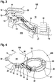
- FIG. 3 shows enlarged the side of the dome cover 100 on which the pivoting mechanism 11 with end stop 12 for opening the dome cover upper part 10 is arranged.
- the pivot mechanism 11 can pivot or flap the dome cover top 10 vertically.
- the pivot arm 13 is arranged between the pivot mechanism 11 and a double-row angular contact ball bearing 15.
- the pivot arm 13 pivots the dome cover upper part 10 in a position parallel to the surface of the container 200, that is to say horizontally.
- Both the The pivot mechanism 11 and the pivot arm 13 can be operated by means of a pneumatic drive 14.
- the gripper 22 is arranged on the surface of the dome cover upper part 10 in the region of the dome cover edge 16 and on the side of the edge of the opening 21 of the container 200 in order to prevent the dome cover 100 from opening.
- Figure 4 shows the in Figure 3 features described and also a dome cover 100 in the open state, both the dome cover upper part 100 and the edge or the nozzle of the opening 21 each having two grippers 22.
- the dome lid upper part 10 is fastened to the swivel mechanism 11 and was moved horizontally to the surface of the container 200 with the swivel arm 13 to the side.
- the pneumatic drive 14 is arranged next to the connection piece of the opening 21 and the angular contact ball bearing 15 of the pivot arm 13.
- the dome cover is shown in the opened state, the edge of the opening 21 having two grippers 22 and two recesses 24.
- the recesses 24 are protruding, that is, they are not let into the edge of the opening 21, but rather form an internally hollow extension at the edge of the opening 21.
- the dome cover upper part 10 is folded on the pivot mechanism 11 up to the end stop 12.
- the receiving groove 23, in which the seal 30 is located, can be seen on the underside of the upper dome cover part 10.
- the dome cover 100 also has a gripper 22 which, in the closed state, comes to rest on the edge of the opening 21 in the same position as the recess 24.
Landscapes
- Engineering & Computer Science (AREA)
- Mechanical Engineering (AREA)
- Health & Medical Sciences (AREA)
- Public Health (AREA)
- Transportation (AREA)
- Closures For Containers (AREA)
- Pressure Vessels And Lids Thereof (AREA)
Abstract
Description
- Die Erfindung betrifft einen Domdeckel zum Verschließen einer Öffnung eines Behälters, wobei der Behälter insbesondere auf einem Fahrzeug oder Fahrgestell montiert ist oder montierbar ist.
- Ein solcher Domdeckel ist beispielsweise bekannt zum Verschließen von Einfüllstutzen oder Mannlöchern von befüllbaren Behältern, beispielsweise von einem Silobehälter oder einem Tank, welche auf einem Fahrzeug, auch einem Schienenfahrzeug oder Anhänger oder auf einem anderen Fahrgestell montiert sein können.
- Ein Deckel beziehungsweise eine Schließeinrichtung wird auch in der
EP 1 917 162 B1 beschrieben. Die beschriebene Schließeinrichtung für das Verschließen eines Einfüllstutzens eines Behälters geeignet, wobei sie beim Verschließen geschwenkt werden kann. Zudem besitzt die Schließeinrichtung eine Dichtung, welche in geschlossenem Zustand den Einfüllstutzen abdichtet. - In der
ES 2 346 507 B1 - In der
EP 3 168 507 A1 wird eine Luke, welche eine Öffnung in einem Tank verschließt, beschrieben. Die Luke ist an einer äußeren Struktur befestigt, welche die Luke auch heben kann. Im geschlossenen Zustand wird die Luke mit einer Dichtung abgedichtet. - In den Beschreibungen der Domdeckel, Luken und Verschlusseinheiten im Stand der Technik sind diese jedoch bisher nicht sowohl schwenkbar als auch klappbar ausgeführt. Eine schwenkbare Ausführung ist vorteilhaft, wenn man platzsparend, vor allem in Richtung oberhalb des Behälters, den Behälter öffnen und verschließen möchte, da hierbei nur ein relativ schmaler Bereich oberhalb des Behälters benötigt wird und ein Einfüllvorgang in den Behälter nicht durch einen aufgestellten Deckel eingeschränkt wird. Ein klappbarer Deckel hat den Vorteil, dass Wartungsarbeiten am Deckel, beispielsweise das Wechseln einer Dichtung, einfacher ausgeführt werden können, da man ungehindert Zugriff zur Unterseite des Deckels hat. Es ist jedoch kein Mechanismus bekannt, welcher beide Vorteile gemeinsam integriert und dabei mit einem Mechanismus die jeweiligen Nachteile der Öffnungsverfahren kompensiert. Des Weiteren sind die im Stand der Technik aufgefundenen Dichtungen nicht darauf ausgelegt, eine möglichst reibungsfreies Verschließen des Deckels möglich zu machen, um das Material der Dichtung zu schonen. Das zuverlässige, schnelle und sichere Verschließen und Abdichten eines Behälters mit Hilfe eines Domdeckels kann durch die in der vorliegenden Erfindung beschriebenen Merkmale verbessert werden.
- Der Erfindung liegt die Aufgabe zugrunde, bei einem Domdeckel der eingangs genannten Art Verschließ- und Dichtungsmechanismus dahingehend zu verbessern, dass der Behälter schneller, sicherer und zuverlässiger verschlossen und abgedichtet werden kann. Dadurch besitzt der Domdeckel zum Verschließen einer Öffnung eines Behälters einen Mechanismus, wodurch das Domdeckeloberteil schwenkbar und/oder klappbar an der Öffnung des Behälters befestigt ist.
- Der Behälter kann dabei ein Tank, eine Tonne, ein Container oder ein andersartiges Gefäß sein, welches auf ein Straßen- und/oder Schienenfahrzeug, einen Anhänger, einen Wagen oder ein anderes bewegliches Gestell montiert sein kann oder montierbar ist. Dabei kann der Behälter zum Transport von Waren geeignet sein, vorzugsweise für Schüttgut, pulverförmige oder körnige Materialien, aber auch von Flüssigkeiten.
- Die Öffnung des Behälters kann ein Einfüllstutzen oder ein Mannloch sein oder eine andere Öffnung im Behälter, die zum Befüllen, Entleeren oder Warten des Behälters verwendet werden kann. Dabei kann die Öffnung an der Oberseite des Behälters angebracht sein, wie beispielsweise bei einem Tank, welcher von oben befüllt wird. Andernfalls kann die Öffnung jedoch auch an der Seite oder an der Unterseite des Behälters angebracht sein, entweder zum Entleeren oder um einen besseren Zugang zum Behälter zu bekommen. Die Größe der Öffnung kann dabei unterschiedlich sein, beispielsweise ist zum Befüllen oder Entleeren von kleinteiligen Materialien eine kleinere Öffnung nötig, als zur Wartung des Behälters, falls dort eine Person hindurchpassen muss. Erfindungsgemäß ist die Öffnung des Behälters jedoch immer mit einem Deckel, einer Luke oder einem anderen beweglichen Teil verschließbar.
- Der Domdeckel beziehungsweise die Vorrichtung, welche die Öffnung des Behälters verschließt, kann dabei erfindungsgemäß einen schwenkbaren Domdeckeloberteil umfassen, welches parallel zur Oberfläche des Behälters bewegbar ist. Das Domdeckeloberteil ist also am Rand der Öffnung angeordnet und horizontal verdrehbar und/oder verschiebbar. Erfindungsgemäß kann das Domdeckeloberteil zusätzlich klappbar, also um eine horizontale Achse schwenkbar, sein, was heißt, dass im Vergleich zur Behälteroberfläche das Domdeckeloberteil vertikal gestellt werden kann. Dazu ist das Domdeckeloberteil am Rand der Öffnung befestigt und kann von dort aus aufgestellt beziehungsweise aufgeklappt werden. Beim Aufstellen und/oder Aufklappen wird das Domdeckeloberteil also um eine Achse geschwenkt, sodass es vertikal zur Behälteroberfläche steht. Dabei kann der Deckel auch um mehr als 90° geklappt werden, sodass er in einer geöffneten Stellung steht.
- Vorzugsweise ist im äußeren Randbereich der Unterseite des Domdeckeloberteils eine Dichtung angeordnet, welche die Öffnung im geschlossenen Zustand abdichtet. Die Dichtung kann dabei umlaufend am Domdeckelrand angeordnet sein, was heißt, dass auf der Unterseite des Domdeckeloberteils in einem geringen Abstand vom Domdeckelrand die Dichtung in Form der Öffnung oder in Form des Domdeckelrandumfangs angeordnet ist. Besonders bevorzugt ist die Dichtung dabei an der Stelle angeordnet, an der sich das Domdeckeloberteil und der Rand der Öffnung berühren, wo also im geschlossenen Zustand die Unterseite des Domdeckeloberteils auf dem Behälter beziehungsweise dem Rand dessen Öffnung aufliegt.
- Bevorzugterweise ist die Dichtung dabei zumindest teilweise in eine Aufnahmenut auf der Unterseite des Domdeckeloberteils eingelassen. Das heißt, dass das Domdeckeloberteil auf seiner Unterseite eine Aufnahmenut aufweist, welche breit genug ist, dass zumindest ein Teil der Dichtung darin Platz hat. Bevorzugterweise verläuft die Aufnahmenut dabei im Randbereich des Domdeckeloberteils, wobei sie bevorzugt parallel zum Umfang des Domdeckeloberteils verläuft und/oder an der Stelle platziert ist an der die Unterseite des Domdeckeloberteils den Rand der Öffnung berührt. In der Aufnahmenut kann dabei die Dichtung platziert werden, sodass die Dichtung zum Teil von der Unterseite des Domdeckeloberteils hervorsteht, jedoch zumindest ein Teil der Dichtung in der Aufnahmenut des Domdeckeloberteils verschwindet. Letzteres ist der Fall, wenn die Aufnahmenut weniger tief ist als die Dichtung hoch ist.
- Bevorzugterweise kann die Innenoberfläche der Aufnahmenut in seiner Form grob der Außenoberfläche der Dichtung entsprechen. Insbesondere hat die Außenoberfläche der Dichtung auf der dem Domdeckeloberteil zugewandten Seite, welche die im Domdeckeloberteil eingelassene Seite ist, die gleiche Form wie die Aufnahmenut, in welcher die Dichtung platziert wird. Das führt dazu, dass die Dichtung möglichst gut am Domdeckeloberteil anliegt. Hierbei sind auch unterschiedliche Außenoberflächen für die Dichtung möglich, was also heißt, dass auch die Aufnahmenut unterschiedliche Innenoberflächen aufweisen kann. Bevorzugterweise sind die Aufnahmenut und/oder die Dichtung zumindest teilweise abgerundet. Oberflächenformen, welche von einer monoton gekrümmten Oberfläche abweichen sind auch möglich, beispielsweise wenn die Aufnahmenut Rillen oder Vertiefungen hat, in die Hervorhebungen, Haken oder Noppen, welche an der äußeren Oberfläche der Dichtung angeordnet sind, eingreifen oder anliegen können, damit die Dichtung im eingesetzten Zustand schwerer verrutscht und besser anliegt beziehungsweise befestigt ist. Besonders bevorzugt kann die Dichtung für einen besseren Halt im Domdeckeloberteil auch in die Aufnahmenut eingeklebt und/oder eingeklemmt werden.
- Besonders bevorzugt weist die Dichtung des Domdeckels einen hohlen Querschnitt auf. Dabei kann die Dichtung auf der Innenoberfläche auf einer Seite konkav geformt sein und auf der gegenüberliegenden Seite konvex ausgebildet sein. Besonders bevorzugt ist dabei die Außenoberfläche auf der Seite der Dichtung, welche in die Unterseite des Domdeckeloberteils eingelassen ist, so geformt, dass sich die Dichtung gut an die Form der Aufnahmenut anschmiegt, die Dichtung ist also auf der Außenseite und auf der Innenseite in Richtung Aufnahmenut gewölbt. Speziell ist dies auch im gedehnten oder aufgeblasenen Zustand der Dichtung der Fall. Auf der gegenüberliegenden Seite, welche zur Öffnung beziehungsweise zum Rand der Öffnung des Behälters zeigt, ist die Dichtung bevorzugt nach innen, also zur Unterseite des Domdeckeloberteils hin, gewölbt. Hier kann die Oberfläche auf der Außenseite und der Innenseite der Dichtung auch unterschiedliche Krümmungen aufweisen, bis hin zu unterschiedlichen Krümmungsrichtungen, wenn beispielsweise die Oberfläche der Dichtung auf der Innenseite zum Domdeckeloberteil hin und auf der Außenseite zum Rand der Öffnung hin gekrümmt ist. Besonders bevorzugt ist bei einer Dichtung mit hohlem Querschnitt der Raum im Innern der Dichtung durchgängig verbunden. Bevorzugterweise ist die Dichtung über- und unterdruckfest, wenn sich Gas im Innern der Dichtung befindet.
- Vorzugsweise ist dabei die Dichtung über eine Anschlussleitung mit einer Luftversorgung verbunden, welche mit einer Steuerung verbunden ist, mittels derer die Luftversorgung in der Dichtung Druck aufbauen und reduzieren kann. Bevorzugterweise wird dabei der Druck in der Dichtung reduziert, wenn das Domdeckeloberteil bewegt wird, und Druck aufgebaut, wenn sich das Domdeckeloberteil im geschlossenen Zustand über der Öffnung befindet. Das hat zur Folge, dass beim Verschwenken des Domdeckeloberteils die Dichtung nicht über den Rand der Öffnung schleift, und diesen bevorzugt auch nicht berührt, und somit kein Verschleiß an der Dichtung entsteht. Der Druck kann beispielsweise dadurch aufgebaut und reduziert werden, dass ein Gas, insbesondere Luft, in die Dichtung eingepumpt oder eingeblasen wird beziehungsweise ausgelassen oder herausgesaugt wird. Die Steuerung der Gasversorgung kann dabei zentral von einem Steuergerät des Fahrzeuges, auf welchem der Behälter montiert ist, gesteuert werden. Alternativ kann die Gasversorgung der Dichtung jedoch auch über ein Paneel direkt an der Öffnung des Behälters oder am Behälter selbst gesteuert werden, beispielsweise gemeinsam mit der Bewegung des Domdeckeloberteils. Besonders bevorzugt reduziert die Steuerung automatisch vor der Bewegung des Domdeckeloberteils in einen geöffneten oder aufgeklappten Zustand den Druck in der Dichtung, sodass sichergestellt ist, dass das Domdeckeloberteil nicht in einem Zustand bewegt wird, in welchem die Dichtung schleifen könnte.
- Vorzugsweise wird die Dichtung vor dem Öffnen und/oder Verschwenken des Domdeckeloberteils über die Steuerung mit Unterdruck beaufschlagt, sodass sich die Dichtung in die Aufnahmenut an der Unterseite des Domdeckeloberteils zurückzieht. Dadurch ist weder eine Abdeckung für die Dichtung noch ein Flansch, der die Dichtung schützt, nötig da durch das Zurückziehen der Dichtung in die Aufnahmenut an der Unterseite des Domdeckeloberteils, die Reibung beim Verschwenken und/oder Öffnen des Domdeckeloberteils vermindert oder ganz verhindert wird. Besonders bevorzugterweise zieht sich die Dichtung vollständig in die Aufnahmenut an der Unterseite des Domdeckeloberteils zurück, bevor das Domdeckeloberteil bewegt wird.
- Bevorzugterweise ist der Domdeckel derart ausgebildet, dass das Domdeckeloberteil zur Wartung aufstellbar ist, beziehungsweise aufgestellt werden kann, wobei die Dichtung in der aufgestellten Position des Domdeckeloberteils überprüft und/oder getauscht werden kann. Die Dichtung ist dabei derart ausgebildet oder kann derart ausgebildet sein, dass sie im aufgestellten Zustand des Domdeckeloberteils leicht entfernt werden kann, beispielsweise wenn die Dichtung mit wenigen Handgriffen aus dem Domdeckeloberteil herausnehmbar ist. Dies ist speziell dann der Fall, wenn die Dichtung durch Hervorhebungen an der Außenseite der Oberfläche in Vertiefungen der Aufnahmenut eingeklemmt werden kann, welche jedoch leicht zu lösen sind, beispielsweise wenn die Dichtung zusammengedrückt wird.
- Bevorzugterweise kann das Domdeckeloberteil im aufgestellten Zustand auch mit einer Überladesicherung ausgestattet sein, welche bei großem Druck auf das Domdeckeloberteil diesen zusätzlich ausschwenkt, falls das Domdeckeloberteil versehentlich im Weg ist und andernfalls die Befestigung des Domdeckeloberteils im ausgeklappten Zustand Schaden nehmen könnte. Beispielsweise kann dies während einem Beladen stattfinden, falls dabei das Domdeckeloberteil versehentlich im ausgeklappten und nicht im aufgeschwenkten Zustand ist. Alternativ dazu kann sichergestellt werden, dass im aufgeklappten Zustand des Domdeckeloberteils keine Beladung stattfindet, indem die Öffnung des Domdeckeloberteils anderweitig gesichert ist, beispielsweise verschlossen ist, und keine Beladung zulässt.
- Besonders bevorzugt verfügt der Domdeckel über ein Drehgelenk, welches mit einem Schwenkarm verbunden ist, über welchen das Domdeckeloberteil mit dem Behälter verbunden ist, wobei im Drehgelenk ein, insbesondere doppelreihiges, Schrägkugellager ausgebildet ist. Das Domdeckeloberteil kann dabei über das Drehgelenk seitlich, also horizontal zur Behälteroberfläche, verschwenkt werden. Entweder kann das Domdeckeloberteil auch über dieses Gelenk geklappt werden, das heißt vertikal zur Behälteroberfläche aufgestellt werden, bevorzugt besitzt der Domdeckel jedoch noch einen separaten Schwenkmechanismus für das vertikalstellen des Domdeckeloberteils. Bevorzugterweise ist dabei am Schwenkmechanismus für die vertikale Position ein Endanschlag angeordnet, welcher verhindert dass das Domdeckeloberteil zu weit ausgelenkt wird. Üblicherweise wird bei einem Drehgelenk eines Schwenkarms eines Domdeckels für das horizontale verschwenken des Domdeckeloberteils statt einem Schrägkugellager, wie bevorzugterweise in der vorliegenden Erfindung, eine Gleithülse verwendet. Das Schreckkugellager bietet jedoch eine bessere Belastbarkeit in axialer und radialer Richtung. Das Drehgelenk ist dabei am Behälter beziehungsweise am Rand der Öffnung des Behälters befestigt und mit der anderen Seite mit dem Schwenkarm verbunden, welcher am Domdeckeloberteil festgemacht ist, und verbindet dabei das Domdeckeloberteil mit dem Behälter, bzw. mit dem Rand der Öffnung des Behälters. Vorzugsweise schwenkt das Drehgelenk dabei das Domdeckeloberteil über einen Schwenkarm um mindestens 90° aus.
- Besonders bevorzugt halten das Drehgelenk und der Schwenkarm das Domdeckeloberteil dabei frei schwebend, das heißt das Domdeckeloberteil benötigt keine Führungsschiene für die Verschwenkung. Der Schwenkarm des Domdeckels ist dabei so konzipiert, dass dieser das Domdeckeloberteil in geöffnetem Zustand horizontal zur Behälteroberfläche frei halten kann. Dadurch ist keine Führungsschiene für das Domdeckeloberteil erforderlich beziehungsweise auch kein Zahnrad oder ein anderer Haltemechanismus für das Domdeckeloberteil im geöffneten Zustand.
- Besonders bevorzugt verfügen das Drehgelenk und/oder der Schwenkarm des Domdeckels dabei über einen pneumatischen oder elektrischen Antrieb. Der pneumatische oder elektrische Antrieb des Drehgelenks beziehungsweise des Schwenkmechanismus ist dabei bevorzugt seitlich außen am Rand der Öffnung angebracht, besonders bevorzugt direkt neben dem Drehgelenk.
- Vorzugsweise ist dabei der Schwenkmechanismus des Domdeckels verstellbar ausgebildet, damit beim Verschleiß der Dichtung eine Nachsteuerbarkeit gegeben ist. Sollte im Verlaufe der Lebenszeit des Domdeckels die Dichtung verschleißen, kann der Schwenkmechanismus entsprechend angepasst werden, um trotzdem einen sicheren Verschluss der Öffnung des Behälters sicherzustellen. Dabei kann beispielsweise der Abstand zwischen Domdeckeloberteil und dem Rand der Öffnung verringert werden, oder die Position des Domdeckeloberteils im geschlossenen Zustand kann nachjustiert werden, bis ein gewisser Druck auf der Dichtung gegeben ist.
- In einer bevorzugten Ausführungsform weißt der Domdeckel am Rand mindestens einen überstehenden Greifer auf, welcher im geschlossenen Zustand des Domdeckeloberteils in eine Ausnehmung am Rand der Öffnung greift. Bevorzugterweise sind dabei mindestens zwei Greifer am Rand des Domdeckeloberteils fix befestigt. Diese sind dabei unterseitig am Domdeckeloberteil befestigt. Ebenso kann der Domdeckel alternativ oder zusätzlich am Rand der Öffnung des Behälters mindestens einen Greifer aufweisen, unter welche der Domdeckelrand beim Verschließen einschwenken kann. Bevorzugterweise sind dabei mindestens zwei Greifer am Rand der Öffnung fix befestigt. Besonders bevorzugt halten diese im geschlossenen Zustand des Domdeckeloberteils diesen partiell an der Oberseite des Domdeckeloberteils, insbesondere an eigen dafür verbreiterten Randbereichen des Domdeckeloberteils. Beim Einschwenken des Domdeckeloberteils bewegen sich die Greifer dabei vorzugsweise nicht, sondern das Domdeckeloberteil schwenkt unterhalb der an der Öffnung oder am Rand der Öffnung befestigten Greifer ein, welche unbeweglich befestigt sind, und die Greifer des Domdeckeloberteils werden in die Ausnehmungen am Rand der Öffnung des Behälters hineinbewegt, ohne sich dabei selbst zu bewegen.
- Die Greifer können dabei starr sein, sich also nicht bewegen beziehungsweise auch nicht aus mehreren ineinandergreifenden Teilen bestehen. An jeder Position ist dabei bevorzugterweise nur ein Greifer, welcher entweder am Domdeckeloberteil oder am Rand beziehungsweise dem Stutzen der Öffnung befestigt sein kann. Dies verhindert ebenfalls das Ineinandergreifen zweier Greifer beziehungsweise Klauen. Bevorzugterweise ist der Greifer aus einem Strangpressprofil gefertigt, welches einen U-förmigen beziehungsweise hakenförmigen Querschnitt hat. Der Greifer kann dabei einfach vom Strangpressprofil abgeschnitten und etwas abgerundet werden und anschließend am Rand der Öffnung beziehungsweise dem Stutzen der Öffnung oder außen am Domdeckelrand aufgebracht werden. Besonders bevorzugt werden die Greifer dabei am Domdeckeloberteil bzw. am Rand der Öffnung angeschweißt. Die Ausnehmung am Rand der Öffnung beziehungsweise am Stutzen der Öffnung des Behälters kann dabei auch hervorstehend sein, also einen Vorsprung darstellen, welcher eine Vertiefung aufweist.
- Des Weiteren umfasst die Erfindung in einem weiteren Aspekt einen Behälter mit einem Domdeckel mit den oben beschriebenen Merkmalen.
- Außerdem umfasst die Erfindung ein Fahrzeug, welches mit einem oben beschriebenen Behälter und Domdeckel ausgestattet ist.
- Einige bevorzugte Ausführungsbeispiele der Erfindung werden in den folgenden Zeichnungen beispielhaft erläutert. Es zeigen schematisch:
- Figur 1
- eine Draufsicht auf einen Domdeckel mit Kragen,
- Figur 2
- einen Schnitt durch einen Rand einer Öffnung eines Behälters und einen Domdeckel mit Dichtung (Schnitt A-A aus
Figur 1 ), - Figur 3
- einen vergrößerten Ausschnitt eines Schwenk und Klappmechanismus eines Domdeckels in geschlossenem Zustand,
- Figur 4
- einen Domdeckel in geöffnetem Zustand mit Schwenkmechanismus, und
- Figur 5
- einen Domdeckel in aufgeklapptem Zustand.
-
Figur 1 zeigt eine Draufsicht auf einen Domdeckel 100, dessen Domdeckeloberteil 10 eine Öffnung 20 (inFigur 1 nicht dargestellt) eines Behälters 200 verschließt. Das Domdeckeloberteil 100 verdeckt dabei in geschlossenem Zustand die Öffnung 20 des Behälters 200 vollständig. Das Domdeckeloberteil 10 ist über einen Schwenkmechanismus 11 und Schwenkarm 13 mit dem Behälter 200 verbunden. Der Schwenkmechanismus 11 dient zum Klappen des Domdeckeloberteils 10 in einen zur Behälteroberfläche vertikalen Zustand, und verfügt über einen Endanschlag 12. Der Endanschlag 12 verhindert ein zu weites Auslenken des Domdeckeloberteils 10 im ausgeklappten Zustand. Der Schwenkmechanismus 11 ist zudem an einem Schwenkarm 13 befestigt, wobei der Schwenkarm 13 das Domdeckeloberteil 10 vertikal zur Oberfläche des Behälters 200 verschwenken kann. Dabei kann im geöffneten Zustand der Schwenkarm 13 das Domdeckeloberteil 10 halten, ohne einen zusätzlichen Verschiebemechanismus zu benötigen. Der Schwenkarm 13 besitzt dabei zudem ein doppelreihiges Schrägkugellager 15. Der Schwenkarm 13 und der Schwenkmechanismus 11 können über einen pneumatischen Antrieb 14 bewegt werden. Am Domdeckeloberteil 10 oder am Rand der Öffnung 21 können dabei Greifer 22 befestigt sein. Die Greifer sind dabei starr angebracht und nicht alleine beziehungsweise unabhängig vom Domdeckeloberteil 10 und dem Rand der Öffnung 21 bewegbar. Der Domdeckelrand 16 schwenkt dabei beim Verschließen der Öffnung 20 mit dem Domdeckeloberteil 10 in die Greifer des Rands der Öffnung 21 ein, sodass diese das Domdeckeloberteil 10 an der Oberseite vor einem Aufklappen schützen. -
Figur 2 zeigt einen Schnitt durch den Domdeckel 100 und dem Rand oder dem Stutzen der Öffnung 21 eines Behälters 200 von den Punkten A bis A (sieheFigur 1 ). Das Domdeckeloberteil 10 wird von einem Greifer 22 umfasst, welcher am Rand der Öffnung 21 angebracht ist. An der Auflagefläche des Domdeckeloberteils 10 auf dem Rand der Öffnung 21 ist eine Aufnahmenut 23 an der Unterseite des Domdeckeloberteils 10 angeordnet. Die Aufnahmenut 23 hat dabei eine Innenoberfläche, welcher der Außenoberfläche der Dichtung 30 angepasst ist, die in die Aufnahmenut 23 eingepasst ist. Insbesondere an der zum Domdeckeloberteil 10 hin gewandten Seite, wo Dichtung 30 und Aufnahmenut 23 aneinander liegen, sind die Oberflächenformen aneinander angepasst. In Richtung des Randes der Öffnung 21 ist die Dichtung 30 dabei zum Domdeckeloberteil 10 hin gebogen, sodass sie in aufgeblasenem Zustand auf dem Rand der Öffnung 21 aufliegt, im Zustand mit Unterdruck jedoch nicht den Rand der Öffnung 21 berührt. Die Dichtung 30 hat einen gasgefüllten Innenraum 31. -
Figur 3 zeigt dabei vergrößert die Seite des Domdeckels 100, an welcher der Schwenkmechanismus 11 mit Endanschlag 12 zum Aufklappen des Domdeckeloberteils 10 angeordnet ist. Der Schwenkmechanismus 11 kann dabei den das Domdeckeloberteil 10 vertikal Schwenken oder Klappen. Der Schwenkarm 13 ist zwischen dem Schwenkmechanismus 11 und einem doppelreihigem Schrägkugellager 15 angeordnet. Der Schwenkarm 13 schwenkt das Domdeckeloberteil 10 in paralleler Lage zur Oberfläche des Behälters 200, also horizontal. Sowohl der Schwenkmechanismus 11 als auch der Schwenkarm 13 können mittels eines pneumatischen Antriebs 14 betrieben werden. Im geschlossenen Zustand ist der Greifer 22 auf der Oberfläche des Domdeckeloberteils 10 im Bereich des Domdeckelrands 16 und an der Seite des Randes der Öffnung 21 des Behälters 200 angeordnet, um ein Aufklappen des Domdeckels 100 zu verhindern. -
Figur 4 zeigt die inFigur 3 beschriebenen Merkmale und außerdem einen Domdeckel 100 im geöffneten Zustand, wobei sowohl das Domdeckeloberteil 100 als auch der Rand beziehungsweise der Stutzen der Öffnung 21 je zwei Greifer 22 aufweisen. Das Domdeckeloberteil 10 ist am Schwenkmechanismus 11 befestigt und wurde mit dem Schwenkarm 13 zur Seite horizontal zur Oberfläche des Behälters 200 bewegt. Der pneumatische Antrieb 14 ist dabei neben dem Stutzen der Öffnung 21 und dem Schrägkugellager 15 des Schwenkarms 13 angeordnet. - In
Figur 5 wird der Domdeckel in aufgeklapptem Zustand gezeigt, wobei der Rand der Öffnung 21 zwei Greifer 22 aufweist und zwei Ausnehmungen 24 umfasst. Die Ausnehmungen 24 sind dabei hervorstehend, das heißt, sie sind nicht in den Rand der Öffnung 21 eingelassen, sondern bilden einen innen hohlen Fortsatz am Rand der Öffnung 21. Das Domdeckeloberteil 10 ist am Schwenkmechanismus 11 bis zum Endanschlag 12 geklappt. Dabei sieht man auf der Unterseite des Domdeckeloberteils 10 die Aufnahmenut 23, in welcher sich die Dichtung 30 befindet. Der Domdeckel 100 verfügt zudem auch über einen Greifer 22, welcher im geschlossenen Zustand auf der gleichen Position am Rand der Öffnung 21 zu liegen kommt, wie die Ausnehmung 24. -
- 100
- Domdeckel
- 200
- Behälter
- 10
- Domdeckeloberteil
- 11
- Schwenkmechanismus
- 12
- Endanschlag
- 13
- Schwenkarm
- 14
- pneumatischer Antrieb
- 15
- Schrägkugellager des Drehgelenks
- 16
- Domdeckelrand
- 20
- Öffnung des Behälters
- 21
- Rand/Stutzen der Öffnung
- 22
- Greifer
- 23
- Aufnahmenut
- 24
- Ausnehmung
- 30
- Dichtung
- 31
- gasgefüllter Innenraum
Claims (15)
- Domdeckel (100) zum Verschließen einer Öffnung (20) eines Behälters (200), insbesondere auf einem Fahrzeug,
gekennzeichnet dadurch,
dass der Domdeckel (100) ein Domdeckeloberteil (10) umfasst, welches schwenkbar und/oder klappbar im Bereich der Öffnung (20) befestigt ist. - Domdeckel (100) gemäß Anspruch 1,
gekennzeichnet dadurch,
dass das Domdeckeloberteil (10) einen äußeren Domdeckelrandbereich (16) umfasst, wobei in diesem Domdeckelrandbereich (16) an der Unterseite des Domdeckeloberteils (10) eine Dichtung (30) angeordnet ist, um im Zusammenwirken mit einem Rand oder Stutzen (21) einer Öffnung (20) die Öffnung (20) im geschlossenen Zustand abzudichten. - Domdeckel (100) gemäß Anspruch 2,
gekennzeichnet dadurch,
dass das Domdeckeloberteil (10) eine Aufnahmenut (23) auf der Unterseite des Domdeckeloberteils (10) aufweist und die Dichtung (30) teilweise in die Aufnahmenut (23) eingelassen ist. - Domdeckel (100) gemäß einem der Ansprüche 2 oder 3,
gekennzeichnet dadurch,
dass die Dichtung (30) einen hohlen Querschnitt aufweist. - Domdeckel (100) gemäß Anspruch 4,
gekennzeichnet dadurch,
dass die Dichtung (30) eine Luftversorgung aufweist, welche mit einer Steuerung verbunden ist, wobei mittels der Luftversorgung in der Dichtung (30) Druck aufgebaut und reduziert werden kann. - Domdeckel (100) gemäß einem der Ansprüche 4 oder 5,
gekennzeichnet dadurch,
dass die Dichtung (30) vor dem Öffnen und/oder Verschwenken des Domdeckeloberteils (10) über die Steuerung mit Unterdruck beaufschlagt wird, sodass die Dichtung (30) sich in die Aufnahmenut(23) an der Unterseite des Domdeckeloberteils (10) zurückzieht. - Domdeckel (100) gemäß einem der Ansprüche 2 bis 6,
gekennzeichnet dadurch,
dass das Domdeckeloberteil (10) zur Wartung aufstellbar ausgebildet ist bzw. aufgestellt ist, wobei die Dichtung (30) des Domdeckels (100) in der aufgestellten Position des Domdeckeloberteils (10) überprüft und/oder getauscht werden kann. - Domdeckel (100) gemäß einem der vorhergehenden Ansprüche,
gekennzeichnet dadurch,
dass der Domdeckel (100) über ein Drehgelenk verfügt, über welches das Domdeckeloberteil (10) mit dem Behälter (200) verbunden ist, wobei im Drehgelenk ein, insbesondere doppelreihiges, Schrägkugellager (15) ausgebildet ist. - Domdeckel (100) gemäß Anspruch 8,
gekennzeichnet dadurch,
dass das Drehgelenk des Domdeckels (100) das Domdeckeloberteil (10) frei schwebend hält und/oder das Domdeckeloberteil (10) nicht über eine Führungsschiene für die Verschwenkung verfügt. - Domdeckel (100) gemäß einem der Ansprüche 8 oder 9,
gekennzeichnet dadurch,
dass des Drehgelenk bzw. der Schwenkmechanismus (11) über einen pneumatischen oder elektrischen Antrieb (14) verfügt. - Domdeckel (100) gemäß einem der Ansprüche 8 bis 10,
gekennzeichnet dadurch,
dass der Schwenkmechanismus (11) vertikal und/oder horizontal verstellbar ausgebildet ist, damit bei einem Verschleiß der Dichtung (30) eine Nachsteuerbarkeit gegeben ist. - Domdeckel (100) gemäß einem der vorhergehenden Ansprüche,
gekennzeichnet dadurch,
dass der Domdeckelrand (16) des Domdeckeloberteils (10) mindestens einen überstehenden Greifer (22) aufweist, der im geschlossenen Zustand des Domdeckeloberteils (10) in eine Ausnehmung (24) am Rand der Öffnung (21) greift. - Domdeckel (100) gemäß einem der vorhergehenden Ansprüche,
gekennzeichnet dadurch,
dass der Rand (21) der Öffnung (20) mindestens einen Greifer (22) aufweist, unter den der Domdeckelrand (16) beim Verschließen einschwenkt. - Behälter (200) mit einer Öffnung (20),
gekennzeichnet dadurch,
dass die Öffnung (20) von einem Domdeckel (100) gemäß einem der vorhergehenden Ansprüche verschließbar ist. - Fahrzeug, insbesondere zur Verwendung auf Straßen oder Schienen,
gekennzeichnet dadurch,
dass das Fahrzeug einen Behälter (200) mit einem Domdeckel (100) gemäß einem der vorhergehenden Ansprüche umfasst.
Applications Claiming Priority (1)
| Application Number | Priority Date | Filing Date | Title |
|---|---|---|---|
| DE202019102372.4U DE202019102372U1 (de) | 2019-04-26 | 2019-04-26 | Domdeckel zum Verschließen einer Öffnung eines Behälters |
Publications (4)
| Publication Number | Publication Date |
|---|---|
| EP3738904A2 true EP3738904A2 (de) | 2020-11-18 |
| EP3738904A3 EP3738904A3 (de) | 2020-12-30 |
| EP3738904B1 EP3738904B1 (de) | 2025-08-20 |
| EP3738904C0 EP3738904C0 (de) | 2025-08-20 |
Family
ID=70227762
Family Applications (1)
| Application Number | Title | Priority Date | Filing Date |
|---|---|---|---|
| EP20164620.5A Active EP3738904B1 (de) | 2019-04-26 | 2020-03-20 | Behälter mit einem domdeckel zum verschliessen einer öffnung des behälters, und fahrzeug damit |
Country Status (4)
| Country | Link |
|---|---|
| EP (1) | EP3738904B1 (de) |
| DE (1) | DE202019102372U1 (de) |
| ES (1) | ES3047088T3 (de) |
| PL (1) | PL3738904T3 (de) |
Citations (3)
| Publication number | Priority date | Publication date | Assignee | Title |
|---|---|---|---|---|
| EP1917162B1 (de) | 2005-08-23 | 2010-04-07 | Stag AG | Schliesseinrichtung für an einem behälter angeordnete einfüllstutzen |
| ES2346507B2 (es) | 2010-03-12 | 2011-08-01 | Jose Ramon Guinart Pallares | Sistema de cierre hermético para recipientes contenedores. |
| EP3168507A1 (de) | 2015-11-16 | 2017-05-17 | Fulgosi S.r.l. | Verschluss für druckschächte |
Family Cites Families (6)
| Publication number | Priority date | Publication date | Assignee | Title |
|---|---|---|---|---|
| DE1907290U (de) * | 1964-06-06 | 1964-12-23 | Blumhardt Fa C | Behaelterfahrzeug, insbesondere tankwagen. |
| JPS6261849A (ja) * | 1985-09-10 | 1987-03-18 | Shin Meiwa Ind Co Ltd | 運搬車の天蓋固縛装置 |
| DK9600149U3 (da) * | 1996-05-01 | 1997-09-12 | Moerch & Soenner A S | Dækselaggregat |
| US7055440B2 (en) * | 2001-01-09 | 2006-06-06 | Delaware Capital Formation | Remotely operated manhole cover for a tanker |
| US8070009B2 (en) * | 2004-01-23 | 2011-12-06 | Rmc Engineering Co., Inc. | Remotely activated tank hatch system |
| US7658570B2 (en) * | 2006-10-02 | 2010-02-09 | Delaware Captial Formation, Inc. | Manhole system |
-
2019
- 2019-04-26 DE DE202019102372.4U patent/DE202019102372U1/de active Active
-
2020
- 2020-03-20 ES ES20164620T patent/ES3047088T3/es active Active
- 2020-03-20 PL PL20164620.5T patent/PL3738904T3/pl unknown
- 2020-03-20 EP EP20164620.5A patent/EP3738904B1/de active Active
Patent Citations (3)
| Publication number | Priority date | Publication date | Assignee | Title |
|---|---|---|---|---|
| EP1917162B1 (de) | 2005-08-23 | 2010-04-07 | Stag AG | Schliesseinrichtung für an einem behälter angeordnete einfüllstutzen |
| ES2346507B2 (es) | 2010-03-12 | 2011-08-01 | Jose Ramon Guinart Pallares | Sistema de cierre hermético para recipientes contenedores. |
| EP3168507A1 (de) | 2015-11-16 | 2017-05-17 | Fulgosi S.r.l. | Verschluss für druckschächte |
Also Published As
| Publication number | Publication date |
|---|---|
| ES3047088T3 (en) | 2025-12-03 |
| PL3738904T3 (pl) | 2026-01-19 |
| DE202019102372U1 (de) | 2020-07-28 |
| EP3738904B1 (de) | 2025-08-20 |
| EP3738904A3 (de) | 2020-12-30 |
| EP3738904C0 (de) | 2025-08-20 |
Similar Documents
| Publication | Publication Date | Title |
|---|---|---|
| DE69718119T2 (de) | Verschlusskappe | |
| EP0502822B1 (de) | Vorrichtung zum Verschieben und Schwenken eines Behälter-Verschlusses | |
| DE1242668B (de) | Schwenkdach fuer Schienen- und Strassenfahrzeuge | |
| DE3627871C2 (de) | ||
| DE20000873U1 (de) | Schwenktürflügel für Fahrzeuge, insbesondere für Busse | |
| EP3738904A2 (de) | Domdeckel zum verschliessen einer öffnung eines behälters, behälter und fahrzeug damit | |
| EP3359367A1 (de) | Vorrichtung und verfahren zum umformen von kunststoffvorformlingen zu kunststoffbehältnissen mit kopplungseinrichtung | |
| DE4215256A1 (de) | Abdichtung an Türen, Luken und Bordwänden für den Kastenaufbau mit Ladefläche bei Lastfahrzeugen | |
| DE3721672C2 (de) | ||
| EP0399212B1 (de) | Füllwagen für eine Koksofenbatterie | |
| DE1605012C3 (de) | Fahrzeug, insbesondere Eisenbahnwagen mit aufklappbarem Dach | |
| DE19548118C2 (de) | Doppeldeckelschleuse zum Verschließen zweier aneinander anschließbarer Öffnungen | |
| DE3732143C2 (de) | ||
| DE9309760U1 (de) | Kraftfahrzeug | |
| EP2139972B1 (de) | Anordnung zum führen einer bohrstange eines decoking-werkzeugs | |
| DE850720C (de) | Entleerungsvorrichtung fuer Muellgefaesse mit Scharnierdeckel | |
| DE2559390B2 (de) | Kohlefuellwagen | |
| DE1034549B (de) | Bunkerverschluss | |
| DE19625691A1 (de) | Kastenkipper | |
| EP2428434A2 (de) | Schließanordnung für einen Fahrzeugbau | |
| AT521151B1 (de) | Anhängerzug mit Motorwagen und Anhänger | |
| DE19509849A1 (de) | Lagerung sowie Öffnungs- und Schließmechanismus für eine Frontklappe am Fahrerhaus eines Frontlenker-Lkw | |
| DE2151935A1 (de) | Vorrichtung zum offenhalten eines kofferraumdeckels | |
| DE2634707A1 (de) | Krankentransportfahrzeug mit als waagerecht geteilter klappe ausgebildeter hinterer ladetuer | |
| DE591202C (de) | Foerdergefaess fuer Bodenentleerung |
Legal Events
| Date | Code | Title | Description |
|---|---|---|---|
| PUAI | Public reference made under article 153(3) epc to a published international application that has entered the european phase |
Free format text: ORIGINAL CODE: 0009012 |
|
| STAA | Information on the status of an ep patent application or granted ep patent |
Free format text: STATUS: REQUEST FOR EXAMINATION WAS MADE |
|
| 17P | Request for examination filed |
Effective date: 20200320 |
|
| AK | Designated contracting states |
Kind code of ref document: A2 Designated state(s): AL AT BE BG CH CY CZ DE DK EE ES FI FR GB GR HR HU IE IS IT LI LT LU LV MC MK MT NL NO PL PT RO RS SE SI SK SM TR |
|
| AX | Request for extension of the european patent |
Extension state: BA ME |
|
| PUAL | Search report despatched |
Free format text: ORIGINAL CODE: 0009013 |
|
| AK | Designated contracting states |
Kind code of ref document: A3 Designated state(s): AL AT BE BG CH CY CZ DE DK EE ES FI FR GB GR HR HU IE IS IT LI LT LU LV MC MK MT NL NO PL PT RO RS SE SI SK SM TR |
|
| AX | Request for extension of the european patent |
Extension state: BA ME |
|
| RIC1 | Information provided on ipc code assigned before grant |
Ipc: B65D 90/58 20060101ALI20201124BHEP Ipc: B65D 90/10 20060101AFI20201124BHEP Ipc: B65D 90/62 20060101ALI20201124BHEP Ipc: B60P 3/22 20060101ALI20201124BHEP Ipc: B65D 90/66 20060101ALI20201124BHEP |
|
| STAA | Information on the status of an ep patent application or granted ep patent |
Free format text: STATUS: EXAMINATION IS IN PROGRESS |
|
| 17Q | First examination report despatched |
Effective date: 20220408 |
|
| GRAP | Despatch of communication of intention to grant a patent |
Free format text: ORIGINAL CODE: EPIDOSNIGR1 |
|
| STAA | Information on the status of an ep patent application or granted ep patent |
Free format text: STATUS: GRANT OF PATENT IS INTENDED |
|
| RIC1 | Information provided on ipc code assigned before grant |
Ipc: B60P 3/22 20060101ALI20250211BHEP Ipc: B65D 90/62 20060101ALI20250211BHEP Ipc: B65D 90/58 20060101ALI20250211BHEP Ipc: B65D 90/10 20060101AFI20250211BHEP |
|
| INTG | Intention to grant announced |
Effective date: 20250310 |
|
| GRAJ | Information related to disapproval of communication of intention to grant by the applicant or resumption of examination proceedings by the epo deleted |
Free format text: ORIGINAL CODE: EPIDOSDIGR1 |
|
| STAA | Information on the status of an ep patent application or granted ep patent |
Free format text: STATUS: EXAMINATION IS IN PROGRESS |
|
| GRAP | Despatch of communication of intention to grant a patent |
Free format text: ORIGINAL CODE: EPIDOSNIGR1 |
|
| STAA | Information on the status of an ep patent application or granted ep patent |
Free format text: STATUS: GRANT OF PATENT IS INTENDED |
|
| GRAS | Grant fee paid |
Free format text: ORIGINAL CODE: EPIDOSNIGR3 |
|
| GRAA | (expected) grant |
Free format text: ORIGINAL CODE: 0009210 |
|
| STAA | Information on the status of an ep patent application or granted ep patent |
Free format text: STATUS: THE PATENT HAS BEEN GRANTED |
|
| INTC | Intention to grant announced (deleted) | ||
| INTG | Intention to grant announced |
Effective date: 20250708 |
|
| AK | Designated contracting states |
Kind code of ref document: B1 Designated state(s): AL AT BE BG CH CY CZ DE DK EE ES FI FR GB GR HR HU IE IS IT LI LT LU LV MC MK MT NL NO PL PT RO RS SE SI SK SM TR |
|
| REG | Reference to a national code |
Ref country code: GB Ref legal event code: FG4D Free format text: NOT ENGLISH |
|
| REG | Reference to a national code |
Ref country code: CH Ref legal event code: EP |
|
| REG | Reference to a national code |
Ref country code: IE Ref legal event code: FG4D Free format text: LANGUAGE OF EP DOCUMENT: GERMAN |
|
| REG | Reference to a national code |
Ref country code: DE Ref legal event code: R096 Ref document number: 502020011657 Country of ref document: DE |
|
| U01 | Request for unitary effect filed |
Effective date: 20250910 |
|
| U07 | Unitary effect registered |
Designated state(s): AT BE BG DE DK EE FI FR IT LT LU LV MT NL PT RO SE SI Effective date: 20250916 |
|
| REG | Reference to a national code |
Ref country code: ES Ref legal event code: FG2A Ref document number: 3047088 Country of ref document: ES Kind code of ref document: T3 Effective date: 20251203 |
|
| PG25 | Lapsed in a contracting state [announced via postgrant information from national office to epo] |
Ref country code: IS Free format text: LAPSE BECAUSE OF FAILURE TO SUBMIT A TRANSLATION OF THE DESCRIPTION OR TO PAY THE FEE WITHIN THE PRESCRIBED TIME-LIMIT Effective date: 20251220 |
|
| PG25 | Lapsed in a contracting state [announced via postgrant information from national office to epo] |
Ref country code: NO Free format text: LAPSE BECAUSE OF FAILURE TO SUBMIT A TRANSLATION OF THE DESCRIPTION OR TO PAY THE FEE WITHIN THE PRESCRIBED TIME-LIMIT Effective date: 20251120 |
|
| PG25 | Lapsed in a contracting state [announced via postgrant information from national office to epo] |
Ref country code: HR Free format text: LAPSE BECAUSE OF FAILURE TO SUBMIT A TRANSLATION OF THE DESCRIPTION OR TO PAY THE FEE WITHIN THE PRESCRIBED TIME-LIMIT Effective date: 20250820 |
|
| PG25 | Lapsed in a contracting state [announced via postgrant information from national office to epo] |
Ref country code: GR Free format text: LAPSE BECAUSE OF FAILURE TO SUBMIT A TRANSLATION OF THE DESCRIPTION OR TO PAY THE FEE WITHIN THE PRESCRIBED TIME-LIMIT Effective date: 20251121 |
|
| PG25 | Lapsed in a contracting state [announced via postgrant information from national office to epo] |
Ref country code: RS Free format text: LAPSE BECAUSE OF FAILURE TO SUBMIT A TRANSLATION OF THE DESCRIPTION OR TO PAY THE FEE WITHIN THE PRESCRIBED TIME-LIMIT Effective date: 20251120 |
|
| PG25 | Lapsed in a contracting state [announced via postgrant information from national office to epo] |
Ref country code: SM Free format text: LAPSE BECAUSE OF FAILURE TO SUBMIT A TRANSLATION OF THE DESCRIPTION OR TO PAY THE FEE WITHIN THE PRESCRIBED TIME-LIMIT Effective date: 20250820 |
|
| U20 | Renewal fee for the european patent with unitary effect paid |
Year of fee payment: 7 Effective date: 20260305 |
|
| PGFP | Annual fee paid to national office [announced via postgrant information from national office to epo] |
Ref country code: GB Payment date: 20260324 Year of fee payment: 7 |
|
| PGFP | Annual fee paid to national office [announced via postgrant information from national office to epo] |
Ref country code: IE Payment date: 20260323 Year of fee payment: 7 |
|
| PG25 | Lapsed in a contracting state [announced via postgrant information from national office to epo] |
Ref country code: CZ Free format text: LAPSE BECAUSE OF FAILURE TO SUBMIT A TRANSLATION OF THE DESCRIPTION OR TO PAY THE FEE WITHIN THE PRESCRIBED TIME-LIMIT Effective date: 20250820 |
|
| PGFP | Annual fee paid to national office [announced via postgrant information from national office to epo] |
Ref country code: PL Payment date: 20260312 Year of fee payment: 7 |
|
| PG25 | Lapsed in a contracting state [announced via postgrant information from national office to epo] |
Ref country code: SK Free format text: LAPSE BECAUSE OF FAILURE TO SUBMIT A TRANSLATION OF THE DESCRIPTION OR TO PAY THE FEE WITHIN THE PRESCRIBED TIME-LIMIT Effective date: 20250820 |