EP3738673B1 - Schleifvorrichtung zum verrunden von partikeln - Google Patents
Schleifvorrichtung zum verrunden von partikeln Download PDFInfo
- Publication number
- EP3738673B1 EP3738673B1 EP20167872.9A EP20167872A EP3738673B1 EP 3738673 B1 EP3738673 B1 EP 3738673B1 EP 20167872 A EP20167872 A EP 20167872A EP 3738673 B1 EP3738673 B1 EP 3738673B1
- Authority
- EP
- European Patent Office
- Prior art keywords
- blowing
- swirl chamber
- particles
- fluid stream
- main flow
- Prior art date
- Legal status (The legal status is an assumption and is not a legal conclusion. Google has not performed a legal analysis and makes no representation as to the accuracy of the status listed.)
- Active
Links
Images


Classifications
-
- B—PERFORMING OPERATIONS; TRANSPORTING
- B24—GRINDING; POLISHING
- B24C—ABRASIVE OR RELATED BLASTING WITH PARTICULATE MATERIAL
- B24C1/00—Methods for use of abrasive blasting for producing particular effects; Use of auxiliary equipment in connection with such methods
- B24C1/006—Methods for use of abrasive blasting for producing particular effects; Use of auxiliary equipment in connection with such methods using material without particles or pellets for deburring, removal of extended surface areas or jet milling of local recessions, e.g. grooves
-
- B—PERFORMING OPERATIONS; TRANSPORTING
- B02—CRUSHING, PULVERISING, OR DISINTEGRATING; PREPARATORY TREATMENT OF GRAIN FOR MILLING
- B02C—CRUSHING, PULVERISING, OR DISINTEGRATING IN GENERAL; MILLING GRAIN
- B02C19/00—Other disintegrating devices or methods
- B02C19/06—Jet mills
-
- B—PERFORMING OPERATIONS; TRANSPORTING
- B02—CRUSHING, PULVERISING, OR DISINTEGRATING; PREPARATORY TREATMENT OF GRAIN FOR MILLING
- B02C—CRUSHING, PULVERISING, OR DISINTEGRATING IN GENERAL; MILLING GRAIN
- B02C19/00—Other disintegrating devices or methods
- B02C19/06—Jet mills
- B02C19/061—Jet mills of the cylindrical type
-
- B—PERFORMING OPERATIONS; TRANSPORTING
- B02—CRUSHING, PULVERISING, OR DISINTEGRATING; PREPARATORY TREATMENT OF GRAIN FOR MILLING
- B02C—CRUSHING, PULVERISING, OR DISINTEGRATING IN GENERAL; MILLING GRAIN
- B02C19/00—Other disintegrating devices or methods
- B02C19/06—Jet mills
- B02C19/068—Jet mills of the fluidised-bed type
-
- B—PERFORMING OPERATIONS; TRANSPORTING
- B24—GRINDING; POLISHING
- B24C—ABRASIVE OR RELATED BLASTING WITH PARTICULATE MATERIAL
- B24C1/00—Methods for use of abrasive blasting for producing particular effects; Use of auxiliary equipment in connection with such methods
-
- B—PERFORMING OPERATIONS; TRANSPORTING
- B24—GRINDING; POLISHING
- B24C—ABRASIVE OR RELATED BLASTING WITH PARTICULATE MATERIAL
- B24C3/00—Abrasive blasting machines or devices; Plants
- B24C3/32—Abrasive blasting machines or devices; Plants designed for abrasive blasting of particular work, e.g. the internal surfaces of cylinder blocks
-
- B—PERFORMING OPERATIONS; TRANSPORTING
- B24—GRINDING; POLISHING
- B24C—ABRASIVE OR RELATED BLASTING WITH PARTICULATE MATERIAL
- B24C9/00—Appurtenances of abrasive blasting machines or devices, e.g. working chambers, arrangements for handling used abrasive material
-
- B—PERFORMING OPERATIONS; TRANSPORTING
- B22—CASTING; POWDER METALLURGY
- B22F—WORKING METALLIC POWDER; MANUFACTURE OF ARTICLES FROM METALLIC POWDER; MAKING METALLIC POWDER; APPARATUS OR DEVICES SPECIALLY ADAPTED FOR METALLIC POWDER
- B22F1/00—Metallic powder; Treatment of metallic powder, e.g. to facilitate working or to improve properties
- B22F1/06—Metallic powder characterised by the shape of the particles
- B22F1/065—Spherical particles
-
- B—PERFORMING OPERATIONS; TRANSPORTING
- B22—CASTING; POWDER METALLURGY
- B22F—WORKING METALLIC POWDER; MANUFACTURE OF ARTICLES FROM METALLIC POWDER; MAKING METALLIC POWDER; APPARATUS OR DEVICES SPECIALLY ADAPTED FOR METALLIC POWDER
- B22F9/00—Making metallic powder or suspensions thereof
- B22F9/02—Making metallic powder or suspensions thereof using physical processes
- B22F9/04—Making metallic powder or suspensions thereof using physical processes starting from solid material, e.g. by crushing, grinding or milling
- B22F2009/044—Making metallic powder or suspensions thereof using physical processes starting from solid material, e.g. by crushing, grinding or milling by jet milling
Definitions
- the invention relates to a grinding device for rounding particles.
- the grinding device comprises a vortex chamber for treating the particles suspended in a fluid stream and is furthermore designed in accordance with claim 1.
- the invention also relates to a corresponding method and the associated use.
- a permanent magnet consists of a magnetizable material, for example iron, cobalt or nickel.
- rare earth metals are added, in particular neodymium, samarium, praseodymium, dysprosium, terbium or gadolinium.
- Rare earth magnets are characterized by the fact that they have a high magnetic remanence flux density and thus a high magnetic energy density.
- Such permanent magnets are made from crystalline powder.
- the magnetic powder is pressed into a mold in the presence of a strong magnetic field. Under the influence of the magnetic field, the crystals align with their preferred magnetization axis in the direction along the magnetic field.
- the pressed parts are then sintered. During sintering, the pulverized components of the powder are bonded or compacted by heating, but none or at least not all of the starting materials are melted. The pressed parts are heated - often under increased pressure - to such an extent that the temperatures remain below the melting temperature of the main components, so that the shape of the workpiece is retained.
- alloys containing rare earth metals can be ground into an intermediate product to produce a starting material such as that required for the manufacture of permanent magnets and in particular for the manufacture of Nd-Fe-B (neodymium-iron-boron) magnets.
- the ground material can be entirely or partially a recycled material from old magnets.
- EP0082816A2 discloses a method for rounding granular solid particles.
- WO 2018/121803 A1 discloses a jet mill designed to generate two fluid flows circulating in opposite directions.
- the invention is based on the object of providing a device for producing smoothed particles of a certain size, ie for producing particles with at least a reduced number of corners and edges.
- the solution according to the invention is achieved by a grinding device for rounding particles according to claim 1.
- the grinding device according to the invention has at least one vortex chamber for treating particles that are suspended in a fluid flow.
- Being suspended means that the particles are at least predominantly carried by the fluid flow for the duration of their processing.
- the fluid flow that moves in the vortex chamber is generated by fluid jets that are blown into the vortex chamber at different points using a blowing device.
- a fluid jet is a locally inflowing, concentrated fluid.
- a fluid jet is concentrated in this sense not only if it has an absolute or average diameter of less than or equal to 10 mm directly at its outlet. The diameter of the fluid jet depends on the nozzle diameter and the nozzle shape (cylindrical or conical), but can also be significantly larger in individual cases.
- the blowing device has a number of first blowing openings for blowing fluid jets into the vortex chamber from the outside. These blowing openings drive a fluid flow that tends to circulate in a first main flow direction around the central axis of the vortex chamber.
- the blowing device also comprises a number of second blowing openings. These are also used to blow fluid jets into the vortex chamber from the outside. These second blowing openings drive a fluid flow that tends to circulate around the center axis of the vortex chamber in a second main flow direction that is opposite to the first main flow direction.
- a turbulent, circular flow is preferably created in the vortex chamber by the aforementioned injection of the fluid jets, not only, but especially when a rapidly rotating separator wheel is also involved in the creation of the flow in the vortex chamber.
- the term "main flow direction” therefore refers (roughly) to the resulting direction in which the local fluid flow or the vertically oriented layer that makes up it, usually of finite thickness, moves overall, regardless of any superimposed local turbulence.
- the solution according to the invention is achieved with the features of claim 9 or 10.
- the blowing device is preferably designed as a guide ring with built-in blowing openings, which can preferably be replaced separately.
- This guide ring then forms a guide wall of the vortex chamber, i.e. a flow guide device. This influences the movement of the fluid flow in the circumferential direction. This is usually done by the guide ring forcing the fluid flow to move in a circular motion in the vortex chamber.
- any wear on the guide ring which is usually abrasive, can easily be compensated for by installing a new guide ring.
- the separate replaceability can be particularly interesting where a multifunctional device is to be implemented: As long as a guide ring with one of the unidirectional blow opening arrangements known from the state of the art is installed, the device can be operated as a jet mill with aggressive blowing.
- the device can be operated as a grinding device with blowing at a lower speed.
- the particles are then - at least essentially - not further broken up. Instead, only their edges are broken or abraded.
- the central longitudinal axes of the first blow openings running in the inflow direction lie in a first common plane that is arranged perpendicular to the imaginary axis around which the fluid flow circles.
- the central longitudinal axes of the second blow openings running in the inflow direction lie in a second common plane that is offset from said first common plane and is arranged perpendicular to the imaginary axis around which the fluid flow circles.
- the offset is preferably 3 mm to 40 mm, better 5 mm to 25 mm.
- the fluid jets from two directly adjacent blowing openings blowing in opposite directions brush against each other essentially tangentially.
- the blowing openings are positioned accordingly and/or equipped with jet-forming nozzles.
- blowing openings it is not mandatory, but ideally, for the blowing openings to be formed by jet-forming nozzles. This allows the injected fluid jets to be shaped in such a way that they fan out later than without nozzle formation. As a result, they retain the ability to drive the desired circular flow in the vortex chamber for longer, at least within the layer they are responsible for influencing.
- the jet-forming nozzles can have a nozzle body that is raised above the inner surface of the guide ring. In this way, the nozzle body protrudes into the circular flow of the suspension - usually more than just insignificantly, namely usually by at least 5 mm in a radially inward direction.
- the nozzles preferably have a nozzle body that is cylindrical or preferably conical in the outlet area. As just described, appropriately designed nozzles release a conically expanding fluid jet into the interior of the vortex chamber and thus produce a particularly effective grinding effect.
- the nozzle bodies are installed in holes in the guide ring.
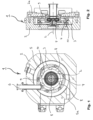
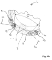
- the grinding device 1 comprises a housing part or a housing 2.
- the housing 2 forms a cavity in its interior.
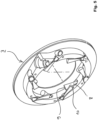
- the cavity accommodates a guide ring 3, which is also called a "nozzle ring" on occasion, at least when it is optionally equipped with nozzles 12.
- the cavity is shown in the Fig.2 preferably closed by a front cover 2a.
- This front cover 2a is ideally designed in such a way that it allows easy and quick access to the cavity when required.
- the guide ring 3 divides the cavity into a vortex chamber 4 and an annular channel 5 surrounding the vortex chamber 4.
- the ring channel 5 is fed with fluid externally via the fluid inlet 5a from a pump or pressure source (not shown here).
- the ring channel 5 serves to continuously supply fluid during the grinding process.
- the vortex chamber 4 is provided with a particle inlet 6.
- the latter is preferably designed as a vertical drop shaft.
- Such an optional design allows the vortex chamber 4 to be loaded with the particles to be ground using gravity during batch operation.
- the loading is then preferably carried out in such a way that at the start of a new grinding cycle, approximately 25% to 50%, or better approximately 30% to 40%, of the volume of the vortex chamber 4 is filled with the particles to be ground.
- the fully rounded particles can optionally be discharged via the classifier wheel, preferably by lowering the classifier wheel speed, which is accompanied by a reduction or elimination of the blocking effect of the classifier wheel.
- the grinding device 1 has a speed control or speed controller for the classifier wheel, which is designed in such a way that it reduces the speed during the discharge process or unloading process.
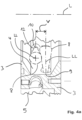
- the grinding device can have one or more additional product outlets 5b, through which the finished rounded particles can be removed, usually independently of or without reducing the classifier speed.
- Fig. 4c shows schematically how such an additional product outlet is designed and arranged.
- the additional product outlet 5b is expediently closed with a flap or a valve 5c.
- the product can then be sucked out.
- the ring channel 5 is passed through a pipe coming from the vortex chamber, penetrating it and leading all the way to the outside, so that the vortex chamber 4 and the ring channel 5 do not come into direct connection with one another due to the additional product outlet.
- the grinding device 1 according to the invention is equipped for continuous operation.
- the product leaves the machine continuously through the sifter wheel, which operates at a suitable speed.
- Satellites are small particles or abrasion that adhere to the actual useful particles and that need to be separated.
- a short stress usually abrasive in the sense of the invention.
- the product made up of the useful particles can then pass through the classifier at a constant classifier speed.
- the example shown here shows the secondary outlet via the classifier wheel 7.
- the classifier wheel is designed in a known manner. It consists of a rotating drum. This in turn typically consists of two flank-forming tires that are connected to one another via spaced-apart bars or blades that are usually parallel to the axis of rotation.
- This separator wheel 7 separates and removes the very fine abrasion which inevitably occurs during grinding and which is usually disruptive to the final product to be ground.
- a fluid flow that corresponds - at least essentially - to the fluid flow that is currently being blown in is drawn off as a classifying fluid flow through the interior of the classifying wheel 7 and from there over its front side facing away from the vortex chamber.
- the classifying fluid flow that flows off in this way entrains the abrasion that is too small and has too little mass to be kept away from the classifying wheel in the center by the centrifugal forces.
- the actual particles which are to be ground for a predetermined period of time, are too large. They circle so strongly in the vortex chamber that the centrifugal forces acting on them keep them away from the classifying wheel in the center. They are also rejected by the classifying wheel - back into the vortex chamber. The actual particles cannot therefore be discharged from the vortex chamber via the classifying wheel.
- the operating speed of the classifying wheel is set accordingly, depending on the size of the particles to be processed or the desired classification quality.
- the processing, ie grinding, of the particles for the purpose of rounding their outer contour or outer surface is carried out by blowing fluid jets into the vortex chamber 4 via the blowing openings 9 and 10. These entrain the particles located in the vortex chamber 4 and drive them in the Vortex chamber 4 creates a fluid flow that mainly circulates around the longitudinal axis L.
- the grinding device typically includes a control system that limits the jet speed of the fluid jets blown in through the blow openings.
- the limitation is such that the particles are not caused to collide with one another and/or impact the housing 2 so violently that they break into comparably large pieces and are thus shattered, i.e. ground, again and again.
- the jet speed is preferably limited to values in the range between 150 m/sec and 300 m/sec, depending on the material currently being ground.
- An essential component of the grinding device according to the invention is its specially designed blowing device.
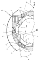
- the blowing device comprises a number of first blowing openings 9.
- the fluid flow emerging from each first blowing opening 9 into the vortex chamber 4 and its jet expansion are schematically represented by a Fluid flow cone 8 is illustrated. These fluid flows drive a fluid flow circulating in a first main flow direction around the central axis of the vortex chamber.
- the blowing device has a number of second blowing openings 10.
- blowing opening 10 is illustrated by the breakout 11, which is only in the Fig.4
- the cutout shows a section of the plane actually behind the plane of the drawing, in which the center lines of the oppositely aligned blow openings 10 are located, or the oppositely acting nozzles 12 that form them.
- the fluid flow exiting from every second blow opening 10 into the vortex chamber 4 and its jet expansion are also illustrated by a fluid flow cone 8 - which, however, is clearly exiting in the opposite direction.
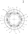
- These fluid flows drive a fluid flow circling around the center axis of the vortex chamber in a second main flow direction, which is opposite to the first main flow direction. This can also be understood quite clearly using the Fig. 4a and 4b .
- the grinding machine according to the invention operates with a kinetic energy that is significantly lower than the kinetic energy used in a jet mill, an unexpectedly strong grinding effect is created when the particles rub against each other in the manner mentioned.
- breakage occurs, it is mainly only fragments whose average diameter is, in many cases, at least one order of magnitude smaller than the average diameter of the remaining particle. As soon as a particle no longer has sharp edges, essentially no further breakage occurs.
- first blowing openings 9 all blow in the same direction and the second blowing openings 10 all blow in the same-opposite direction.
- the respective first blow openings 9 are arranged at an angle A of approximately 15° to 45° and ideally of 25° to 35° relative to the tangent which is applied to the inner circumferential surface of the guide ring in the region of the mouth of the respective blow opening 9 in the guide ring 3, cf. Fig.4 .
- the second blow openings 10 are arranged at an opposite angle B of approximately 15° to 45° and ideally of 25° to 35° relative to the tangent that is applied to the inner surface of the guide ring 3 in the area of the outlet of the respective blow opening 10 in the guide ring 3, see also Fig.4 .
- FIG. 4a Another preferred dimensioning rule is derived from Fig. 4a , which essentially Fig.4 Blow openings 9, 10 which are immediately adjacent to one another along the shortest path form a blow opening pair angle C of between 45° and 90°, preferably between 45° and 60°, with the perpendiculars to their central longitudinal axes LL.
- the number of pairs of counter-rotating blow openings 9 and 10 should ideally be 4 to 12 and better only 4 to 8.
- the blowing openings 9 and 10 are preferably formed by nozzles 12, the nozzle body of which is a separate component which is fixed, preferably screwed, in the guide ring 3.
- the guide ring 3 has a number of holes which penetrate it obliquely in a radially inward direction. A nozzle body is fixed or screwed into each of these holes.
- the grinding device according to the invention does not have to be a stand-alone device. Rather, it is possible to equip one of the known jet mills, such as the Conjet type from the applicant, in such a way that it can be used for a different purpose as a grinding machine according to the invention.
- a guide ring 3 equipped with the appropriate jet is inserted into the existing machine and then it is ensured that the existing machine only operates with a significantly reduced jet speed, as is absolutely necessary for the invention.
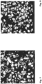
- the Figure 7 shows particles made of a permanent magnetic material (rare earths) ground using a conventional jet mill at 5,000x SEM magnification. The inadequate rounding of the particles, which extends to the point of sharp edges, is clearly visible.
- the Figure 8 the same material after grinding, preferably for several minutes, in a grinding device according to the invention.
- the rounding quality is significantly better.
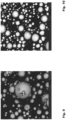
- FIG 9 shows particles that were ground round using a different method that is not in accordance with the invention. It is particularly noticeable in the large particle in the center of the picture how heavily it is contaminated with fine, dust-like abrasion particles, which are disruptive in many applications.
- Figure 10 shows particles that are The grinding device according to the invention has been used to grind them round. Their contamination with satellite-like abrasion particles is practically zero.
Landscapes
- Engineering & Computer Science (AREA)
- Mechanical Engineering (AREA)
- Food Science & Technology (AREA)
- Disintegrating Or Milling (AREA)
Applications Claiming Priority (1)
| Application Number | Priority Date | Filing Date | Title |
|---|---|---|---|
| DE102019112791.2A DE102019112791B3 (de) | 2019-05-15 | 2019-05-15 | Schleifvorrichtung zum verrunden von partikeln |
Publications (3)
| Publication Number | Publication Date |
|---|---|
| EP3738673A1 EP3738673A1 (de) | 2020-11-18 |
| EP3738673C0 EP3738673C0 (de) | 2024-07-31 |
| EP3738673B1 true EP3738673B1 (de) | 2024-07-31 |
Family
ID=70289250
Family Applications (1)
| Application Number | Title | Priority Date | Filing Date |
|---|---|---|---|
| EP20167872.9A Active EP3738673B1 (de) | 2019-05-15 | 2020-04-03 | Schleifvorrichtung zum verrunden von partikeln |
Country Status (4)
| Country | Link |
|---|---|
| EP (1) | EP3738673B1 (pl) |
| CN (1) | CN111941287B (pl) |
| DE (1) | DE102019112791B3 (pl) |
| PL (1) | PL3738673T3 (pl) |
Family Cites Families (18)
| Publication number | Priority date | Publication date | Assignee | Title |
|---|---|---|---|---|
| US2191095A (en) * | 1937-09-01 | 1940-02-20 | Internat Pulverizing Corp | Centrifugal fluid jet pulverizer |
| US3436868A (en) * | 1965-03-19 | 1969-04-08 | Christensen Diamond Prod Co | Rounding and polishing apparatus for crystalline carbon bodies |
| CH667223A5 (de) * | 1981-12-23 | 1988-09-30 | Alusuisse | Verfahren und vorrichtung zum abrunden koerniger feststoffpartikel. |
| JPH0657310B2 (ja) * | 1987-03-24 | 1994-08-03 | ホソカワミクロン株式会社 | 無機質結晶体粒子の整粒方法 |
| CN2239294Y (zh) * | 1995-07-28 | 1996-11-06 | 薛彬 | 双圆盘对撞式气流粉碎机 |
| MY128139A (en) | 2000-03-31 | 2007-01-31 | Neomax Co Ltd | Blasting apparatus |
| JP3562643B2 (ja) * | 2001-09-03 | 2004-09-08 | 株式会社セイシン企業 | ジェットミルの砕料供給装置 |
| JP3786190B2 (ja) * | 2001-10-31 | 2006-06-14 | 信越化学工業株式会社 | 希土類焼結磁石の製造方法 |
| JP2005533666A (ja) * | 2002-07-23 | 2005-11-10 | イワノヴィチ グレチシュキン オレグ | 吹付け加工装置 |
| JP5149568B2 (ja) * | 2007-09-04 | 2013-02-20 | 株式会社不二製作所 | 研削加工方法及び研削加工装置 |
| TWI513547B (zh) * | 2009-09-11 | 2015-12-21 | Sintokogio Ltd | Spraying material recovery apparatus and jetting processing apparatus and jetting processing method including jetting material recovery apparatus |
| CN101698923B (zh) * | 2009-09-29 | 2012-08-29 | 昆山新浦瑞金属材料有限公司 | 一种钢丸及其制备方法 |
| CN102407493A (zh) * | 2010-09-24 | 2012-04-11 | 鸿富锦精密工业(深圳)有限公司 | 磨圆装置及磨圆方法 |
| DE102010048777B4 (de) | 2010-10-18 | 2013-10-31 | Fraunhofer-Gesellschaft zur Förderung der angewandten Forschung e.V. | Verfahren und Vorrichtung zur Oberflächenbehandlung eines Objektes |
| TW201446329A (zh) * | 2013-03-11 | 2014-12-16 | 道達爾研究及技術弗呂公司 | 用噴射磨製造形態優化的細顆粒的方法、用於該方法的噴射磨和所製造的顆粒 |
| CN103991037B (zh) * | 2014-05-28 | 2016-08-24 | 山东开泰抛丸机械股份有限公司 | 不锈钢丝切丸磨圆机及磨圆方法 |
| EP3393669B1 (en) * | 2016-12-28 | 2019-09-18 | Houdek, Jan | Device and method for micronization of solid materials |
| CN109453908B (zh) * | 2019-01-09 | 2020-09-04 | 山东中鹏特种陶瓷有限公司 | 螺旋喷嘴制造工艺 |
-
2019
- 2019-05-15 DE DE102019112791.2A patent/DE102019112791B3/de active Active
-
2020
- 2020-04-03 PL PL20167872.9T patent/PL3738673T3/pl unknown
- 2020-04-03 EP EP20167872.9A patent/EP3738673B1/de active Active
- 2020-05-08 CN CN202010383693.2A patent/CN111941287B/zh active Active
Also Published As
| Publication number | Publication date |
|---|---|
| CN111941287A (zh) | 2020-11-17 |
| PL3738673T3 (pl) | 2024-11-04 |
| EP3738673C0 (de) | 2024-07-31 |
| EP3738673A1 (de) | 2020-11-18 |
| DE102019112791B3 (de) | 2020-06-18 |
| CN111941287B (zh) | 2022-10-25 |
Similar Documents
| Publication | Publication Date | Title |
|---|---|---|
| DE69813201T2 (de) | Kontrollierte zerkleinerung von stoffen in einer wirbelkammer | |
| DE69618431T2 (de) | Mechanischer Zerkleinerungsapparat | |
| EP2637790B1 (de) | Verfahren zur zerkleinerung von mahlgut und wälzmühle | |
| EP2527040B1 (de) | Verfahren zum betrieb einer strahlmühle sowie strahlmühle | |
| DE19635500B4 (de) | Vorrichtung zur Hochenergie- und/oder Feinstmahlung von Feststoffen und Verfahren zu dessen Betrieb | |
| EP0603481B1 (de) | Verfahren und Anlage zur Zerkleinerung von Mahlgut | |
| DE102013110352A1 (de) | Zerkleinerungsvorrichtung | |
| DE102011050789A1 (de) | Vorrichtung zum mechanischen Trennen von Materialkonglomeraten aus Materialen unterschiedlicher Dichte und/oder Konsistenz | |
| DE3140294C2 (de) | Verfahren und Vorrichtung zum Trennen eines Gutgemisches in Komponenten unterschiedlicher Mahlbarkeit | |
| WO2013167398A1 (de) | Zerkleinerungsvorrichtung | |
| EP1080786B1 (de) | Verfahren zur Fliessbettstrahlmahlung, Vorrichtung zur Durchführung dieses Verfahrens und Anlage mit einer solchen Vorrichtung zur Durchführung dieses Verfahrens | |
| EP2482987B1 (de) | Verfahren und vorrichtung zur zerkleinerung von erzmaterial | |
| EP4512771A1 (de) | Verfahren zur erhöhung der ausbeute an verrundeten graphitartikeln | |
| EP3738673B1 (de) | Schleifvorrichtung zum verrunden von partikeln | |
| DE3730597C2 (de) | Strahlmühle | |
| EP3603811B1 (de) | Zerkleinerungsverfahren und -anlage | |
| EP3895806A1 (de) | Vorrichtung und verfahren zum zerkleinern von festen materialien | |
| EP3849714B1 (de) | Sichtrad mit segelflächenelementen und verfahren zum sichten mit einem solchen sichtrad | |
| DE69212362T2 (de) | Verfahren und Vorrichtung zum Pulverisieren von schwer zu zerbrechenden Kunststoffen | |
| EP1043073B1 (de) | Nassklassiereinrichtung mit integriertem Mahlwerk | |
| DE400307C (de) | Verfahren und Vorrichtung zur Herstellung feiner Pulver bis herab zur kolloidalen Feinheit, vornehmlich aus Metallen | |
| DE902708C (de) | Maschine zur Herstellung von feinstzerteilten Mischungen, Dispersionen oder Emulsionen | |
| DE4431534B4 (de) | Maschine zur Einwirkung auf zerkleinerbares und klassierbares Rohgut, sowie Verfahren zum Betrieb der Maschine | |
| DE10018005A1 (de) | Verfahren und Vorrichtung zum Pulverisieren von spanartigem Material | |
| DE19718668A1 (de) | Verfahren zum Trennen und kontinuierlichen Austragen von schwer dispergierbaren Bestandteilen |
Legal Events
| Date | Code | Title | Description |
|---|---|---|---|
| PUAI | Public reference made under article 153(3) epc to a published international application that has entered the european phase |
Free format text: ORIGINAL CODE: 0009012 |
|
| STAA | Information on the status of an ep patent application or granted ep patent |
Free format text: STATUS: THE APPLICATION HAS BEEN PUBLISHED |
|
| AK | Designated contracting states |
Kind code of ref document: A1 Designated state(s): AL AT BE BG CH CY CZ DE DK EE ES FI FR GB GR HR HU IE IS IT LI LT LU LV MC MK MT NL NO PL PT RO RS SE SI SK SM TR |
|
| AX | Request for extension of the european patent |
Extension state: BA ME |
|
| STAA | Information on the status of an ep patent application or granted ep patent |
Free format text: STATUS: REQUEST FOR EXAMINATION WAS MADE |
|
| 17P | Request for examination filed |
Effective date: 20210305 |
|
| RBV | Designated contracting states (corrected) |
Designated state(s): AL AT BE BG CH CY CZ DE DK EE ES FI FR GB GR HR HU IE IS IT LI LT LU LV MC MK MT NL NO PL PT RO RS SE SI SK SM TR |
|
| GRAP | Despatch of communication of intention to grant a patent |
Free format text: ORIGINAL CODE: EPIDOSNIGR1 |
|
| STAA | Information on the status of an ep patent application or granted ep patent |
Free format text: STATUS: GRANT OF PATENT IS INTENDED |
|
| GRAS | Grant fee paid |
Free format text: ORIGINAL CODE: EPIDOSNIGR3 |
|
| INTG | Intention to grant announced |
Effective date: 20240603 |
|
| GRAA | (expected) grant |
Free format text: ORIGINAL CODE: 0009210 |
|
| STAA | Information on the status of an ep patent application or granted ep patent |
Free format text: STATUS: THE PATENT HAS BEEN GRANTED |
|
| AK | Designated contracting states |
Kind code of ref document: B1 Designated state(s): AL AT BE BG CH CY CZ DE DK EE ES FI FR GB GR HR HU IE IS IT LI LT LU LV MC MK MT NL NO PL PT RO RS SE SI SK SM TR |
|
| REG | Reference to a national code |
Ref country code: CH Ref legal event code: EP Ref country code: GB Ref legal event code: FG4D Free format text: NOT ENGLISH |
|
| REG | Reference to a national code |
Ref country code: DE Ref legal event code: R096 Ref document number: 502020008708 Country of ref document: DE |
|
| REG | Reference to a national code |
Ref country code: IE Ref legal event code: FG4D Free format text: LANGUAGE OF EP DOCUMENT: GERMAN |
|
| U01 | Request for unitary effect filed |
Effective date: 20240802 |
|
| U07 | Unitary effect registered |
Designated state(s): AT BE BG DE DK EE FI FR IT LT LU LV MT NL PT SE SI Effective date: 20240822 |
|
| REG | Reference to a national code |
Ref country code: GR Ref legal event code: EP Ref document number: 20240401990 Country of ref document: GR Effective date: 20241007 |
|
| PG25 | Lapsed in a contracting state [announced via postgrant information from national office to epo] |
Ref country code: NO Free format text: LAPSE BECAUSE OF FAILURE TO SUBMIT A TRANSLATION OF THE DESCRIPTION OR TO PAY THE FEE WITHIN THE PRESCRIBED TIME-LIMIT Effective date: 20241031 |
|
| PG25 | Lapsed in a contracting state [announced via postgrant information from national office to epo] |
Ref country code: IS Free format text: LAPSE BECAUSE OF FAILURE TO SUBMIT A TRANSLATION OF THE DESCRIPTION OR TO PAY THE FEE WITHIN THE PRESCRIBED TIME-LIMIT Effective date: 20241130 |
|
| PG25 | Lapsed in a contracting state [announced via postgrant information from national office to epo] |
Ref country code: HR Free format text: LAPSE BECAUSE OF FAILURE TO SUBMIT A TRANSLATION OF THE DESCRIPTION OR TO PAY THE FEE WITHIN THE PRESCRIBED TIME-LIMIT Effective date: 20240731 |
|
| PG25 | Lapsed in a contracting state [announced via postgrant information from national office to epo] |
Ref country code: RS Free format text: LAPSE BECAUSE OF FAILURE TO SUBMIT A TRANSLATION OF THE DESCRIPTION OR TO PAY THE FEE WITHIN THE PRESCRIBED TIME-LIMIT Effective date: 20241031 Ref country code: ES Free format text: LAPSE BECAUSE OF FAILURE TO SUBMIT A TRANSLATION OF THE DESCRIPTION OR TO PAY THE FEE WITHIN THE PRESCRIBED TIME-LIMIT Effective date: 20240731 |
|
| PG25 | Lapsed in a contracting state [announced via postgrant information from national office to epo] |
Ref country code: RS Free format text: LAPSE BECAUSE OF FAILURE TO SUBMIT A TRANSLATION OF THE DESCRIPTION OR TO PAY THE FEE WITHIN THE PRESCRIBED TIME-LIMIT Effective date: 20241031 Ref country code: NO Free format text: LAPSE BECAUSE OF FAILURE TO SUBMIT A TRANSLATION OF THE DESCRIPTION OR TO PAY THE FEE WITHIN THE PRESCRIBED TIME-LIMIT Effective date: 20241031 Ref country code: IS Free format text: LAPSE BECAUSE OF FAILURE TO SUBMIT A TRANSLATION OF THE DESCRIPTION OR TO PAY THE FEE WITHIN THE PRESCRIBED TIME-LIMIT Effective date: 20241130 Ref country code: HR Free format text: LAPSE BECAUSE OF FAILURE TO SUBMIT A TRANSLATION OF THE DESCRIPTION OR TO PAY THE FEE WITHIN THE PRESCRIBED TIME-LIMIT Effective date: 20240731 Ref country code: ES Free format text: LAPSE BECAUSE OF FAILURE TO SUBMIT A TRANSLATION OF THE DESCRIPTION OR TO PAY THE FEE WITHIN THE PRESCRIBED TIME-LIMIT Effective date: 20240731 |
|
| PG25 | Lapsed in a contracting state [announced via postgrant information from national office to epo] |
Ref country code: SM Free format text: LAPSE BECAUSE OF FAILURE TO SUBMIT A TRANSLATION OF THE DESCRIPTION OR TO PAY THE FEE WITHIN THE PRESCRIBED TIME-LIMIT Effective date: 20240731 |
|
| PG25 | Lapsed in a contracting state [announced via postgrant information from national office to epo] |
Ref country code: CZ Free format text: LAPSE BECAUSE OF FAILURE TO SUBMIT A TRANSLATION OF THE DESCRIPTION OR TO PAY THE FEE WITHIN THE PRESCRIBED TIME-LIMIT Effective date: 20240731 |
|
| PG25 | Lapsed in a contracting state [announced via postgrant information from national office to epo] |
Ref country code: SK Free format text: LAPSE BECAUSE OF FAILURE TO SUBMIT A TRANSLATION OF THE DESCRIPTION OR TO PAY THE FEE WITHIN THE PRESCRIBED TIME-LIMIT Effective date: 20240731 |
|
| U20 | Renewal fee for the european patent with unitary effect paid |
Year of fee payment: 6 Effective date: 20250424 |
|
| PLBE | No opposition filed within time limit |
Free format text: ORIGINAL CODE: 0009261 |
|
| STAA | Information on the status of an ep patent application or granted ep patent |
Free format text: STATUS: NO OPPOSITION FILED WITHIN TIME LIMIT |
|
| 26N | No opposition filed |
Effective date: 20250501 |
|
| PGFP | Annual fee paid to national office [announced via postgrant information from national office to epo] |
Ref country code: PL Payment date: 20250401 Year of fee payment: 6 |
|
| PGFP | Annual fee paid to national office [announced via postgrant information from national office to epo] |
Ref country code: GB Payment date: 20250426 Year of fee payment: 6 |
|
| PGFP | Annual fee paid to national office [announced via postgrant information from national office to epo] |
Ref country code: GR Payment date: 20250424 Year of fee payment: 6 |
|
| REG | Reference to a national code |
Ref country code: CH Ref legal event code: H13 Free format text: ST27 STATUS EVENT CODE: U-0-0-H10-H13 (AS PROVIDED BY THE NATIONAL OFFICE) Effective date: 20251125 |
|
| PG25 | Lapsed in a contracting state [announced via postgrant information from national office to epo] |
Ref country code: MC Free format text: LAPSE BECAUSE OF FAILURE TO SUBMIT A TRANSLATION OF THE DESCRIPTION OR TO PAY THE FEE WITHIN THE PRESCRIBED TIME-LIMIT Effective date: 20240731 |
|
| PG25 | Lapsed in a contracting state [announced via postgrant information from national office to epo] |
Ref country code: CH Free format text: LAPSE BECAUSE OF NON-PAYMENT OF DUE FEES Effective date: 20250430 |
|
| PG25 | Lapsed in a contracting state [announced via postgrant information from national office to epo] |
Ref country code: IE Free format text: LAPSE BECAUSE OF NON-PAYMENT OF DUE FEES Effective date: 20250403 |
|
| PG25 | Lapsed in a contracting state [announced via postgrant information from national office to epo] |
Ref country code: RO Free format text: LAPSE BECAUSE OF FAILURE TO SUBMIT A TRANSLATION OF THE DESCRIPTION OR TO PAY THE FEE WITHIN THE PRESCRIBED TIME-LIMIT Effective date: 20240731 |
|
| PGFP | Annual fee paid to national office [announced via postgrant information from national office to epo] |
Ref country code: TR Payment date: 20260330 Year of fee payment: 7 |