EP3736348A1 - Verfahren zur herstellung eines aufgestickten verpackungsstahls - Google Patents
Verfahren zur herstellung eines aufgestickten verpackungsstahls Download PDFInfo
- Publication number
- EP3736348A1 EP3736348A1 EP20177041.9A EP20177041A EP3736348A1 EP 3736348 A1 EP3736348 A1 EP 3736348A1 EP 20177041 A EP20177041 A EP 20177041A EP 3736348 A1 EP3736348 A1 EP 3736348A1
- Authority
- EP
- European Patent Office
- Prior art keywords
- nitrogen
- steel product
- steel
- flat steel
- cold
- Prior art date
- Legal status (The legal status is an assumption and is not a legal conclusion. Google has not performed a legal analysis and makes no representation as to the accuracy of the status listed.)
- Granted
Links
Images



Classifications
-
- C—CHEMISTRY; METALLURGY
- C21—METALLURGY OF IRON
- C21D—MODIFYING THE PHYSICAL STRUCTURE OF FERROUS METALS; GENERAL DEVICES FOR HEAT TREATMENT OF FERROUS OR NON-FERROUS METALS OR ALLOYS; MAKING METAL MALLEABLE, e.g. BY DECARBURISATION OR TEMPERING
- C21D9/00—Heat treatment, e.g. annealing, hardening, quenching or tempering, adapted for particular articles; Furnaces therefor
- C21D9/46—Heat treatment, e.g. annealing, hardening, quenching or tempering, adapted for particular articles; Furnaces therefor for sheet metals
-
- C—CHEMISTRY; METALLURGY
- C21—METALLURGY OF IRON
- C21C—PROCESSING OF PIG-IRON, e.g. REFINING, MANUFACTURE OF WROUGHT-IRON OR STEEL; TREATMENT IN MOLTEN STATE OF FERROUS ALLOYS
- C21C7/00—Treating molten ferrous alloys, e.g. steel, not covered by groups C21C1/00 - C21C5/00
-
- C—CHEMISTRY; METALLURGY
- C21—METALLURGY OF IRON
- C21D—MODIFYING THE PHYSICAL STRUCTURE OF FERROUS METALS; GENERAL DEVICES FOR HEAT TREATMENT OF FERROUS OR NON-FERROUS METALS OR ALLOYS; MAKING METAL MALLEABLE, e.g. BY DECARBURISATION OR TEMPERING
- C21D1/00—General methods or devices for heat treatment, e.g. annealing, hardening, quenching or tempering
- C21D1/34—Methods of heating
- C21D1/40—Direct resistance heating
-
- C—CHEMISTRY; METALLURGY
- C21—METALLURGY OF IRON
- C21D—MODIFYING THE PHYSICAL STRUCTURE OF FERROUS METALS; GENERAL DEVICES FOR HEAT TREATMENT OF FERROUS OR NON-FERROUS METALS OR ALLOYS; MAKING METAL MALLEABLE, e.g. BY DECARBURISATION OR TEMPERING
- C21D1/00—General methods or devices for heat treatment, e.g. annealing, hardening, quenching or tempering
- C21D1/34—Methods of heating
- C21D1/42—Induction heating
-
- C—CHEMISTRY; METALLURGY
- C21—METALLURGY OF IRON
- C21D—MODIFYING THE PHYSICAL STRUCTURE OF FERROUS METALS; GENERAL DEVICES FOR HEAT TREATMENT OF FERROUS OR NON-FERROUS METALS OR ALLOYS; MAKING METAL MALLEABLE, e.g. BY DECARBURISATION OR TEMPERING
- C21D1/00—General methods or devices for heat treatment, e.g. annealing, hardening, quenching or tempering
- C21D1/74—Methods of treatment in inert gas, controlled atmosphere, vacuum or pulverulent material
- C21D1/76—Adjusting the composition of the atmosphere
-
- C—CHEMISTRY; METALLURGY
- C21—METALLURGY OF IRON
- C21D—MODIFYING THE PHYSICAL STRUCTURE OF FERROUS METALS; GENERAL DEVICES FOR HEAT TREATMENT OF FERROUS OR NON-FERROUS METALS OR ALLOYS; MAKING METAL MALLEABLE, e.g. BY DECARBURISATION OR TEMPERING
- C21D8/00—Modifying the physical properties of ferrous metals or ferrous alloys by deformation combined with, or followed by, heat treatment
- C21D8/02—Modifying the physical properties of ferrous metals or ferrous alloys by deformation combined with, or followed by, heat treatment during manufacturing of plates or strips
- C21D8/0221—Modifying the physical properties of ferrous metals or ferrous alloys by deformation combined with, or followed by, heat treatment during manufacturing of plates or strips characterised by the working steps
- C21D8/0226—Hot rolling
-
- C—CHEMISTRY; METALLURGY
- C21—METALLURGY OF IRON
- C21D—MODIFYING THE PHYSICAL STRUCTURE OF FERROUS METALS; GENERAL DEVICES FOR HEAT TREATMENT OF FERROUS OR NON-FERROUS METALS OR ALLOYS; MAKING METAL MALLEABLE, e.g. BY DECARBURISATION OR TEMPERING
- C21D8/00—Modifying the physical properties of ferrous metals or ferrous alloys by deformation combined with, or followed by, heat treatment
- C21D8/02—Modifying the physical properties of ferrous metals or ferrous alloys by deformation combined with, or followed by, heat treatment during manufacturing of plates or strips
- C21D8/0221—Modifying the physical properties of ferrous metals or ferrous alloys by deformation combined with, or followed by, heat treatment during manufacturing of plates or strips characterised by the working steps
- C21D8/0236—Cold rolling
-
- C—CHEMISTRY; METALLURGY
- C21—METALLURGY OF IRON
- C21D—MODIFYING THE PHYSICAL STRUCTURE OF FERROUS METALS; GENERAL DEVICES FOR HEAT TREATMENT OF FERROUS OR NON-FERROUS METALS OR ALLOYS; MAKING METAL MALLEABLE, e.g. BY DECARBURISATION OR TEMPERING
- C21D8/00—Modifying the physical properties of ferrous metals or ferrous alloys by deformation combined with, or followed by, heat treatment
- C21D8/02—Modifying the physical properties of ferrous metals or ferrous alloys by deformation combined with, or followed by, heat treatment during manufacturing of plates or strips
- C21D8/0247—Modifying the physical properties of ferrous metals or ferrous alloys by deformation combined with, or followed by, heat treatment during manufacturing of plates or strips characterised by the heat treatment
- C21D8/0257—Modifying the physical properties of ferrous metals or ferrous alloys by deformation combined with, or followed by, heat treatment during manufacturing of plates or strips characterised by the heat treatment with diffusion of elements, e.g. decarburising, nitriding
-
- C—CHEMISTRY; METALLURGY
- C21—METALLURGY OF IRON
- C21D—MODIFYING THE PHYSICAL STRUCTURE OF FERROUS METALS; GENERAL DEVICES FOR HEAT TREATMENT OF FERROUS OR NON-FERROUS METALS OR ALLOYS; MAKING METAL MALLEABLE, e.g. BY DECARBURISATION OR TEMPERING
- C21D8/00—Modifying the physical properties of ferrous metals or ferrous alloys by deformation combined with, or followed by, heat treatment
- C21D8/02—Modifying the physical properties of ferrous metals or ferrous alloys by deformation combined with, or followed by, heat treatment during manufacturing of plates or strips
- C21D8/0247—Modifying the physical properties of ferrous metals or ferrous alloys by deformation combined with, or followed by, heat treatment during manufacturing of plates or strips characterised by the heat treatment
- C21D8/0273—Final recrystallisation annealing
-
- C—CHEMISTRY; METALLURGY
- C21—METALLURGY OF IRON
- C21D—MODIFYING THE PHYSICAL STRUCTURE OF FERROUS METALS; GENERAL DEVICES FOR HEAT TREATMENT OF FERROUS OR NON-FERROUS METALS OR ALLOYS; MAKING METAL MALLEABLE, e.g. BY DECARBURISATION OR TEMPERING
- C21D9/00—Heat treatment, e.g. annealing, hardening, quenching or tempering, adapted for particular articles; Furnaces therefor
- C21D9/0062—Heat-treating apparatus with a cooling or quenching zone
-
- C—CHEMISTRY; METALLURGY
- C21—METALLURGY OF IRON
- C21D—MODIFYING THE PHYSICAL STRUCTURE OF FERROUS METALS; GENERAL DEVICES FOR HEAT TREATMENT OF FERROUS OR NON-FERROUS METALS OR ALLOYS; MAKING METAL MALLEABLE, e.g. BY DECARBURISATION OR TEMPERING
- C21D9/00—Heat treatment, e.g. annealing, hardening, quenching or tempering, adapted for particular articles; Furnaces therefor
- C21D9/52—Heat treatment, e.g. annealing, hardening, quenching or tempering, adapted for particular articles; Furnaces therefor for wires; for strips ; for rods of unlimited length
- C21D9/54—Furnaces for treating strips or wire
- C21D9/56—Continuous furnaces for strip or wire
- C21D9/561—Continuous furnaces for strip or wire with a controlled atmosphere or vacuum
-
- C—CHEMISTRY; METALLURGY
- C22—METALLURGY; FERROUS OR NON-FERROUS ALLOYS; TREATMENT OF ALLOYS OR NON-FERROUS METALS
- C22C—ALLOYS
- C22C38/00—Ferrous alloys, e.g. steel alloys
-
- C—CHEMISTRY; METALLURGY
- C22—METALLURGY; FERROUS OR NON-FERROUS ALLOYS; TREATMENT OF ALLOYS OR NON-FERROUS METALS
- C22C—ALLOYS
- C22C38/00—Ferrous alloys, e.g. steel alloys
- C22C38/001—Ferrous alloys, e.g. steel alloys containing N
-
- C—CHEMISTRY; METALLURGY
- C23—COATING METALLIC MATERIAL; COATING MATERIAL WITH METALLIC MATERIAL; CHEMICAL SURFACE TREATMENT; DIFFUSION TREATMENT OF METALLIC MATERIAL; COATING BY VACUUM EVAPORATION, BY SPUTTERING, BY ION IMPLANTATION OR BY CHEMICAL VAPOUR DEPOSITION, IN GENERAL; INHIBITING CORROSION OF METALLIC MATERIAL OR INCRUSTATION IN GENERAL
- C23C—COATING METALLIC MATERIAL; COATING MATERIAL WITH METALLIC MATERIAL; SURFACE TREATMENT OF METALLIC MATERIAL BY DIFFUSION INTO THE SURFACE, BY CHEMICAL CONVERSION OR SUBSTITUTION; COATING BY VACUUM EVAPORATION, BY SPUTTERING, BY ION IMPLANTATION OR BY CHEMICAL VAPOUR DEPOSITION, IN GENERAL
- C23C8/00—Solid state diffusion of only non-metal elements into metallic material surfaces; Chemical surface treatment of metallic material by reaction of the surface with a reactive gas, leaving reaction products of surface material in the coating, e.g. conversion coatings, passivation of metals
- C23C8/02—Pretreatment of the material to be coated
-
- C—CHEMISTRY; METALLURGY
- C23—COATING METALLIC MATERIAL; COATING MATERIAL WITH METALLIC MATERIAL; CHEMICAL SURFACE TREATMENT; DIFFUSION TREATMENT OF METALLIC MATERIAL; COATING BY VACUUM EVAPORATION, BY SPUTTERING, BY ION IMPLANTATION OR BY CHEMICAL VAPOUR DEPOSITION, IN GENERAL; INHIBITING CORROSION OF METALLIC MATERIAL OR INCRUSTATION IN GENERAL
- C23C—COATING METALLIC MATERIAL; COATING MATERIAL WITH METALLIC MATERIAL; SURFACE TREATMENT OF METALLIC MATERIAL BY DIFFUSION INTO THE SURFACE, BY CHEMICAL CONVERSION OR SUBSTITUTION; COATING BY VACUUM EVAPORATION, BY SPUTTERING, BY ION IMPLANTATION OR BY CHEMICAL VAPOUR DEPOSITION, IN GENERAL
- C23C8/00—Solid state diffusion of only non-metal elements into metallic material surfaces; Chemical surface treatment of metallic material by reaction of the surface with a reactive gas, leaving reaction products of surface material in the coating, e.g. conversion coatings, passivation of metals
- C23C8/06—Solid state diffusion of only non-metal elements into metallic material surfaces; Chemical surface treatment of metallic material by reaction of the surface with a reactive gas, leaving reaction products of surface material in the coating, e.g. conversion coatings, passivation of metals using gases
- C23C8/08—Solid state diffusion of only non-metal elements into metallic material surfaces; Chemical surface treatment of metallic material by reaction of the surface with a reactive gas, leaving reaction products of surface material in the coating, e.g. conversion coatings, passivation of metals using gases only one element being applied
- C23C8/24—Nitriding
- C23C8/26—Nitriding of ferrous surfaces
-
- C—CHEMISTRY; METALLURGY
- C23—COATING METALLIC MATERIAL; COATING MATERIAL WITH METALLIC MATERIAL; CHEMICAL SURFACE TREATMENT; DIFFUSION TREATMENT OF METALLIC MATERIAL; COATING BY VACUUM EVAPORATION, BY SPUTTERING, BY ION IMPLANTATION OR BY CHEMICAL VAPOUR DEPOSITION, IN GENERAL; INHIBITING CORROSION OF METALLIC MATERIAL OR INCRUSTATION IN GENERAL
- C23C—COATING METALLIC MATERIAL; COATING MATERIAL WITH METALLIC MATERIAL; SURFACE TREATMENT OF METALLIC MATERIAL BY DIFFUSION INTO THE SURFACE, BY CHEMICAL CONVERSION OR SUBSTITUTION; COATING BY VACUUM EVAPORATION, BY SPUTTERING, BY ION IMPLANTATION OR BY CHEMICAL VAPOUR DEPOSITION, IN GENERAL
- C23C8/00—Solid state diffusion of only non-metal elements into metallic material surfaces; Chemical surface treatment of metallic material by reaction of the surface with a reactive gas, leaving reaction products of surface material in the coating, e.g. conversion coatings, passivation of metals
- C23C8/80—After-treatment
-
- F—MECHANICAL ENGINEERING; LIGHTING; HEATING; WEAPONS; BLASTING
- F27—FURNACES; KILNS; OVENS; RETORTS
- F27D—DETAILS OR ACCESSORIES OF FURNACES, KILNS, OVENS OR RETORTS, IN SO FAR AS THEY ARE OF KINDS OCCURRING IN MORE THAN ONE KIND OF FURNACE
- F27D11/00—Arrangement of elements for electric heating in or on furnaces
- F27D11/02—Ohmic resistance heating
- F27D11/04—Ohmic resistance heating with direct passage of current through the material being heated
-
- F—MECHANICAL ENGINEERING; LIGHTING; HEATING; WEAPONS; BLASTING
- F27—FURNACES; KILNS; OVENS; RETORTS
- F27D—DETAILS OR ACCESSORIES OF FURNACES, KILNS, OVENS OR RETORTS, IN SO FAR AS THEY ARE OF KINDS OCCURRING IN MORE THAN ONE KIND OF FURNACE
- F27D11/00—Arrangement of elements for electric heating in or on furnaces
- F27D11/06—Induction heating, i.e. in which the material being heated, or its container or elements embodied therein, form the secondary of a transformer
-
- F—MECHANICAL ENGINEERING; LIGHTING; HEATING; WEAPONS; BLASTING
- F27—FURNACES; KILNS; OVENS; RETORTS
- F27D—DETAILS OR ACCESSORIES OF FURNACES, KILNS, OVENS OR RETORTS, IN SO FAR AS THEY ARE OF KINDS OCCURRING IN MORE THAN ONE KIND OF FURNACE
- F27D3/00—Charging; Discharging; Manipulation of charge
- F27D3/16—Introducing a fluid jet or current into the charge
-
- F—MECHANICAL ENGINEERING; LIGHTING; HEATING; WEAPONS; BLASTING
- F27—FURNACES; KILNS; OVENS; RETORTS
- F27D—DETAILS OR ACCESSORIES OF FURNACES, KILNS, OVENS OR RETORTS, IN SO FAR AS THEY ARE OF KINDS OCCURRING IN MORE THAN ONE KIND OF FURNACE
- F27D3/00—Charging; Discharging; Manipulation of charge
- F27D3/16—Introducing a fluid jet or current into the charge
- F27D2003/166—Introducing a fluid jet or current into the charge the fluid being a treatment gas
-
- Y—GENERAL TAGGING OF NEW TECHNOLOGICAL DEVELOPMENTS; GENERAL TAGGING OF CROSS-SECTIONAL TECHNOLOGIES SPANNING OVER SEVERAL SECTIONS OF THE IPC; TECHNICAL SUBJECTS COVERED BY FORMER USPC CROSS-REFERENCE ART COLLECTIONS [XRACs] AND DIGESTS
- Y02—TECHNOLOGIES OR APPLICATIONS FOR MITIGATION OR ADAPTATION AGAINST CLIMATE CHANGE
- Y02P—CLIMATE CHANGE MITIGATION TECHNOLOGIES IN THE PRODUCTION OR PROCESSING OF GOODS
- Y02P10/00—Technologies related to metal processing
- Y02P10/25—Process efficiency
Definitions
- the invention relates to a method for producing an embroidered packaging steel with the features of claim 1.
- the embroidery of flat steel products such as sheet steel or steel strips, which are intended for the production of packaging is known from the prior art.
- packaging steel The embroidery of flat steel products such as sheet steel or steel strips, which are intended for the production of packaging (hereinafter referred to as packaging steel), is known from the prior art.
- a steel sheet for packaging purposes and a method for its production is described, which was made of an aluminum-calmed, continuously cast carbon-manganese steel and has received an amount of unbound, dissolved nitrogen by embroidery, the minimum amount of unbound nitrogen depending on a
- the desired hardness category of the steel sheet is defined and (for example for hardness category T61 of the European Standard 145-78) has an amount of unbound nitrogen of at least 5 ppm.
- the chemical composition of the steel sheet disclosed there corresponds to the usual soft steels with regard to the carbon and manganese content and has, for example, a carbon content in the range of 0.03-0.1% by weight and a manganese content of 0.15-0.5% by weight. -% on.
- the steel sheet is characterized by a high yield point in the range of 350-550 N / mm 2 .
- a maximum value of 100 ppm is given for the amount of unbound nitrogen dissolved in the steel, which explains why the steel sheet with a higher content of unbound nitrogen can no longer be cold-rolled due to the associated increase in strength and therefore not for its intended use as cold-rolled packaging steel suitable is.
- the thermal aftertreatment can expediently be combined with another thermal treatment of the re-rolled steel, which is to be carried out in any case in the context of the production of a packaging steel, such as melting a tin layer electrolytically applied to the surface of the steel sheet or baking a paint layer applied to the steel sheet surface .
- the embroidering of a steel can be carried out during the production process of the steel by introducing nitrogen into the molten steel, for example by blowing in nitrogen gas N 2 .
- a method for embroidering molten steel in steel production in the oxygen blowing process is, for example, in DE 2 237 498 described.
- Flat steel products, in particular steel strips, can be embroidered by surface conditioning, for example by diffusing nitrogen into the sheet steel surface, which can be done, for example, by gas nitriding in an ammonia atmosphere at a slight excess pressure, by bath nitriding in nitrogen-containing salt baths or by plasma nitriding.
- the diffusion of nitrogen forms a hard, superficial connecting layer on the sheet steel surface and a diffusion zone below, in which the nitrogen is stored up to a certain depth in the (ferritic) steel matrix.
- the object of the invention is to provide a flat steel product (sheet steel or steel strip) for the production of packaging which has the highest possible strength with at the same time good elongation at break and good forming properties.
- a packaging steel with strengths of at least 600 MPa with an elongation at break of at least 5% is to be made available.
- the higher-strength packaging steel must also have sufficient formability for the intended use as packaging steel, for example in deep-drawing or ironing processes, so that packaging, such as food or beverage cans, can be manufactured from the flat steel product as intended.
- the packaging steel present as a flat steel product should have the usual thicknesses in the thin and ultra-thin sheet range, which are usually in the range from 0.1 to 0.5 mm (fine sheet) or 0.5 to 3 mm (fine sheet) and are produced by cold rolling .
- an embroidered packaging steel with a carbon content of 400 to 1200 ppm and an amount of unbound nitrogen dissolved in the steel of more than 100 ppm and preferably more than 150 ppm and particularly preferably more than 210 ppm can be produced, with First a hot-rolled and possibly already embroidered steel product is cold-rolled into a steel flat product, the cold-rolled steel flat product is then annealed in an annealing furnace in a recrystallizing manner, a nitrogen-containing gas being introduced into the annealing furnace and directed at the steel flat product to remove unbound nitrogen in the steel flat product in an amount corresponding to a concentration of more than 100 ppm or to increase the amount of unbound nitrogen in the flat steel product to a concentration of more than 100 ppm. Immediately after the annealing, the flat steel product is cooled at a cooling rate of at least 100 K / s.
- the cold-rolled flat steel product is initially heated in the annealing furnace in a first heating step to a holding temperature (T h ) below the Acl temperature and in particular in the range from 600 ° C to 650 ° C and in a subsequent holding step to this holding temperature (T h ) held in order to act on the cold-rolled flat steel product at the holding temperature (T h ) for embroidery with the nitrogen-containing gas.
- T h holding temperature below the Acl temperature and in particular in the range from 600 ° C to 650 ° C and in a subsequent holding step to this holding temperature (T h ) held in order to act on the cold-rolled flat steel product at the holding temperature (T h ) for embroidery with the nitrogen-containing gas.
- the cold-rolled flat steel product is first heated in the annealing furnace to a holding temperature (T h ) above the Acl temperature and in particular heated in the range from 740 ° C to 760 ° C and held at this holding temperature (T h ) in a subsequent holding step, the cold-rolled flat steel product being subjected to the nitrogen-containing gas during the heating step and / or during the holding step for embroidery.
- T h holding temperature
- T h holding temperature
- a multiphase structure is formed in the flat steel product, which comprises ferrite and at least one of the structural components martensite, bainite, troostite / pearlite and / or retained austenite.
- Steel products with such a structure have a higher strength than monophase steels.
- the nitrogen concentration in the steel is increased to value ranges (of more than 100 ppm), which also cause an increase in strength.
- the carbon content of the steel should be at least 0.04% by weight for the formation of a multiphase structure.
- the upper limit of the carbon content is given on the one hand by the upper limits of approx. 0.12% by weight required by the standards for packaging steel (as defined in the ASTM A623-11 standard) and on the other hand by the technological properties of cold-rollability, whereby experience has shown that a hot-rolled steel product has more than 0.12% by weight carbon content can only be cold-rolled with great difficulty.
- the embroidering of the steel can expediently take place in two stages.
- a steel melt is nitrided to a nitrogen content of at most 160 ppm by adding nitrogen to the steel melt, for example in the form of a nitrogen-containing gas and / or a nitrogen-containing solid.
- a slab is cast from the steel melt embroidered in this way and hot-rolled to form a hot strip.
- the hot strip is then, if necessary, pickled (after cooling to ambient temperature) and cold-rolled to form a flat steel product (sheet steel or steel strip).
- the cold-rolled flat steel product is then annealed to recrystallize in the annealing furnace.
- the second stage of nitrogenization is carried out in the annealing furnace by introducing a nitrogen-containing gas into the annealing furnace and directing it onto the flat steel product by the amount of unbound nitrogen in the steel to further increase the amount of nitrogen already introduced into the steel melt in the first stage of embroidery.
- the two-stage embroidery of the packaging steel ensures that the hot strip can be easily cold-rolled into a flat steel product, in particular a steel strip, with the cold rolling devices (rolling mills) usually used for the production of packaging steels.
- This is made possible by the fact that a content of unbound nitrogen of at most 160 ppm is introduced into the steel melt in the first stage of embroidery.
- the hot strip produced from the embroidered molten steel by hot rolling remains cold-rollable with these nitrogen contents, so that a thin or ultra-fine sheet can be produced from the hot strip by cold rolling in the thicknesses customary for packaging purposes. Higher nitrogen contents in the steel melt also lead to undesirable defects in the slab cast from the steel melt.
- the desired strength of the packaging steel of preferably more than 600 MPa is achieved during cold rolling and in the second stage of embroidering the flat steel product during its recrystallizing annealing.
- flat steel products, in particular steel strips, with thicknesses in the fine and ultra-fine sheet metal range, in particular in the range from 0.1 to 0.5 mm, for use as packaging steel with very high tensile strengths and at the same time high elongation at break of preferably at least 5% can be produced without a To suffer limitation in the forming properties.
- the steel melt is embroidered in the first stage by introducing nitrogen gas (N 2 ) and / or calcium cyanamide (CaCN 2 ) and / or manganese nitrogen (MnN) into the steel melt.
- nitrogen gas N 2
- CaCN 2 calcium cyanamide
- MnN manganese nitrogen
- the flat steel product is preferably embroidered in the second stage by introducing ammonia gas (NH 3 ) into the annealing furnace, in which the flat steel product is annealed in a recrystallizing manner.
- the ammonia gas is expediently gassed onto the surface of the flat steel product by means of spray nozzles.
- the amount of ammonia gas that is introduced into the annealing furnace is preferably adjusted so that an ammonia equilibrium with an ammonia concentration in the range of 0.05 to 15% is established in the annealing furnace (in% by weight, based on the gas atmosphere in the annealing furnace) .
- the ammonia concentration in the annealing furnace required for effective embroidery depends on the temperature in the annealing furnace.
- ammonia concentration in the annealing furnace At ideal temperatures, range from 600 to 650 ° C ammonia concentration in the range from 0.05 to 1.5% by weight in order to store the desired amounts of unbound nitrogen (interstitial) in the flat steel product when embroidering. At higher temperatures, especially above 700 ° C, the ammonia concentration in the annealing furnace must be selected to be correspondingly higher (up to 15% by weight) in order to store nitrogen in significant quantities in the flat steel product.
- the ammonia concentration in the annealing furnace is preferably recorded by means of an ammonia sensor and the recorded measured value of the ammonia equilibrium concentration is used to regulate the amount of ammonia gas introduced into the annealing furnace per unit of time.
- an inert gas is also introduced into the annealing furnace, for example nitrogen gas and / or hydrogen gas or a mixture thereof, for example in a composition of 95% by weight Nitrogen gas and 5 wt% hydrogen gas.
- the annealing furnace thus also acts as a closed inert chamber.
- the steel strip passed through the annealing furnace therefore does not come into contact with an oxidizing environment and, in particular, with atmospheric oxygen during the recrystallizing annealing and embroidery until it cools, which is why the formation of oxide layers on the surface of the steel strip can be avoided.
- the total amounts of unbound nitrogen introduced by the two-stage embroidery on the packaging steel are between 100 and 500 ppm, preferably above 150 ppm and particularly preferably in the range between 210 and 350 ppm.
- a nitrogen content of at most 160 ppm is introduced into the steel melt.
- Compliance with an upper limit of approx. 160 ppm for the content of unbound nitrogen in the molten steel ensures that no defects arise on the slab produced from the molten steel, for example in the form of pores and cracks, which can be oxidized by ambient oxygen.
- the hot strip produced from the slab can still be cold rolled with a nitrogen content of at most 160 ppm.
- the embroidery can also be carried out in one stage, in which case the cold-rolled flat steel product is only embroidered by exposure to a nitrogen-containing gas in the continuous furnace during the recrystallizing annealing.
- the amount of unbound nitrogen that can be introduced (possibly as a second stage) when embroidering the flat steel product in the annealing furnace by applying a nitrogen-containing gas (possibly additionally) is in the range from 100 to 350 ppm.
- a total amount of unbound nitrogen of preferably more than 150 ppm and particularly preferably more than 210 ppm and up to 500 ppm can be introduced into the packaging steel produced according to the invention. This allows tensile strengths of more than 650 MPa and up to 1000 MPa to be achieved, whereby a linear relationship has been established between the content of unbound nitrogen and the tensile strength and, for example, for tensile strengths of approx. 650 MPa a content of unbound nitrogen of approx 210 ppm is required.
- the multiphase structure of the steel produced by the heat treatment according to the invention contributes to increasing the strength of the cold-rolled flat steel product.
- the cold-rolled flat steel product is heated in a heating step during recrystallizing annealing to temperatures above the Acl temperature (which is usually around 723 ° C for the alloy composition of the steel used). It has been shown that in order to form a multiphase structure it is necessary to heat the flat steel product at least briefly to a temperature above the Acl temperature. The heating can take place either by thermal radiation in the annealing furnace or inductively or conductively, with very high heating rates of more than 500 K / s being able to be achieved via inductive or conductive heating.
- the cold-rolled flat steel product When the cold-rolled flat steel product is heated, it is kept at temperatures above the recrystallization temperature for a sufficiently long heating period in order to anneal the flat steel product in a recrystallizing manner, whereby the formability of the cold-rolled flat steel product is restored. After (at least briefly) heating to temperatures above the Acl temperature, the flat steel product is rapidly cooled, a cooling rate of at least 100 K / s and preferably more than 150 K / s to be observed in order to form a multi-phase structure in the steel.
- the flat steel product is expediently subjected to an annealing cycle with predetermined temperature profiles in the annealing furnace.
- the cold-rolled flat steel product is initially heated in a continuous annealing furnace (by thermal radiation) from ambient temperature at a heating rate of expediently 15 to 25 K / s and in particular of 20 K / s to a holding temperature above the recrystallization temperature but still below the Acl temperature and in particular in the range from 600 ° C.
- the holding temperature (T h ) is expediently selected so that the most efficient possible storage of nitrogen in the flat steel product can be ensured. It has been shown that this is the case in particular in the temperature range between 600 ° C and 650 ° C.
- the ammoniac concentration in the annealing furnace can be set to low values in the range from 0.05 to 1.5% by weight.
- the flat steel product is heated in a second heating step to an annealing temperature (T g ) above the Acl temperature and preferably between 740 ° C ⁇ T g ⁇ 760 ° C and then at a cooling rate of more than 100 K / s cooled down.
- the heating rate in the second heating step is preferably more than 100 K / s and particularly preferably more than 500 K / s, the heating in the second heating step being advantageously inductive or conductive in order to achieve such high heating rates. Heating rates of over 1000 K / s can be achieved by means of inductive or conductive heating.
- the cooling at the preferred cooling rate of more than 100 K / s can be carried out either by means of a cold gas stream (preferably an inert gas such as hydrogen or nitrogen) or by introducing the flat steel product into a quenching liquid (e.g. a water tank), the flat steel product preferably at ambient temperature is cooled.
- a cold gas stream preferably an inert gas such as hydrogen or nitrogen
- a quenching liquid e.g. a water tank
- the cold-rolled flat steel product is first heated in a continuous annealing furnace (by thermal radiation) in a (single) heating step from ambient temperature with a heating rate of advantageously more than 15 K / s to a holding temperature (T h ) above Acl -Temperature and in particular in the range from 740 ° C to 760 ° C and held in a subsequent holding step for a holding time at this holding temperature (T h ), the cold-rolled steel flat product during the heating step and / or during the holding step for embroidery with the nitrogen-containing Gas is applied.
- the flat steel product is preferably exposed to the nitrogen-containing gas during the heating step, since it has been shown that nitrogenization is most efficient at temperatures below approx. 700 ° C and in particular in the temperature range from 600 ° C to 660 ° C.
- the holding time during which the flat steel product is kept at temperatures above the Ac1 temperature is expediently in the range from 80 to 150 seconds and, for example, about 100-110 seconds.
- a plurality of spray nozzles is preferably used, with which a nitrogen-containing gas, such as e.g. Ammonia gas, can be applied uniformly to the surface of the flat steel product running through the annealing furnace.
- a nitrogen-containing gas such as e.g. Ammonia gas
- the multiple spray nozzles are arranged, for example, transversely to the strip running direction and preferably at an equidistant distance from one another. This enables the flat steel product to be embroidered homogeneously over the entire surface.
- a steel product manufactured by continuous casting and hot-rolled with a Thickness ranging from 2 to 15 mm thick and with a carbon content of 400 to 1200 ppm is used.
- the alloy composition of the steel expediently fulfills the limit values specified by standards for packaging steel (as defined, for example, in ASTM A623-11 "Standard Specification for Tin Mill Products” or in "European Standard EN 10202").
- the steel product used as the starting product preferably has the following upper limits for the weight proportion of the alloy components (in order to bring the end product into line with the cited standards for packaging steel): - C: Max. 0.12%, - Mn: Max. 0.4%, - Si: Max.
- a steel product with such an alloy composition is first converted into a flat steel product (steel sheet or steel strip) with a thickness reduction of 50% to 96% up to a final thickness in the fine or ultra-fine sheet range (approx. 0.1 to 0.5 mm) cold rolled.
- the steel product is expediently rolled into a steel strip and wound up as a roll (coil).
- the flat steel product is then fed into an annealing furnace in order to on the one hand to anneal recrystallized and on the other hand to embroider to nitrogen concentrations of more than 100 ppm and preferably of more than 210 ppm.
- the flat steel product is advantageously cooled to room temperature according to the invention at a cooling rate of at least 100 K / s.
- the cold-rolled steel strip In order to restore the crystal structure of the steel that was destroyed during the cold rolling of the steel product, the cold-rolled steel strip must be annealed in a recrystallizing manner.
- This is done according to the invention by passing the cold-rolled steel strip through an annealing furnace, which is expediently designed as a continuous annealing furnace, through which the flat steel product, which is expediently a steel strip, is passed through at a speed of more than 200 m / min.
- the flat steel product referred to below as steel strip
- the steel strip is stitched on at the same time as the recrystallization annealing.
- a nitrogen-containing gas preferably ammonia (NH 3 )
- NH 3 ammonia
- the steel strip is subjected to an annealing cycle (annealing process with a time-changing temperature profile of the steel strip) in the annealing furnace.
- FIG. 3 a first embodiment of a suitable annealing cycle according to the invention is shown in the form of the time profile of the temperature (T) of the steel strip guided through the annealing furnace.
- T temperature
- the steel strip is initially heated in the annealing furnace in a first heating step I from room temperature to a holding temperature (T h ).
- the steel strip is heated in the first heating step by thermal radiation in the heated annealing furnace at a (comparatively low) heating rate of 15 to 25 K / s and in particular of approx. 20 K / s.
- the holding temperature (T h ) is expediently just above the recrystallization temperature of the steel and preferably in the range from 600.degree. C. to 650.degree.
- the temperature of the steel strip is in a holding step II following the first heating step I at the holding temperature (T h ) over a first holding time (t h1 ) of approx. 60 to 200 seconds and preferably from 80 to 150 seconds, in particular from approx. 100 to 110 seconds.
- a nitrogen-containing gas is applied to the steel strip in an embroidery phase A, preferably over the entire holding time (t h1 ), in order to embroider the steel strip (i.e.
- the steel strip becomes very fast in a second (short) heating step III (preferably within a short heating time between approx. 0.1 s and 10), with a heating rate of more than 100 K / s and preferably heated by more than 500 K / s to a temperature above the Ac1 temperature of the steel, in particular to temperatures in the range from 725 ° C to 800 ° C.
- the second heating step III is carried out inside the annealing furnace by inductive or conductive heating of the steel strip.
- an induction or a conduction heater is arranged inside the annealing furnace, through which the steel strip is guided in the second heating step III.
- the second heating step III is followed by a short, second holding step IV, in which the steel strip is subjected to induction or conduction heating out and its temperature over a (short) second holding time (t h2 ), which is in the range of a few seconds (for example. Between 0.1 and 10 seconds and in particular about 2 seconds), is kept above the Acl temperature.
- the steel strip is led out of the annealing furnace and, in a cooling step V outside the annealing furnace, is cooled to room temperature at a cooling rate of at least 100 K / s.
- the cooling step V immediately follows the (short) second holding time (t h2 ).
- the cooling can take place, for example, by means of a cold gas stream which is directed onto the surface of the steel strip, or by introducing the steel strip into a cooling liquid, for example into a water bath.
- a coolant higher cooling rates in the range of >> 1000 K / s can be achieved. Quenching the steel strip with a cooling liquid is more expensive in terms of equipment.
- the at least short-term heating of the flat steel product to temperatures above the Acl temperature (approx. 723 ° C) is guaranteed in the annealing cycle of Figure 3a that the steel comes into the 2-phase area (alpha and gamma iron), which in turn enables a multi-phase structure to form during the subsequent (rapid) cooling.
- the embroidery in this annealing cycle can be embroidered during the first holding step II at significantly lower temperatures (in the range from 600 ° C. to 650 ° C.), which enables greater efficiency of the embroidery and a lower consumption of nitrogen-containing gas.
- the steel strip is first heated in the annealing furnace in a (single) heating step I from room temperature to a holding temperature (T h ), the holding temperature (T h ) - unlike in the first embodiment of FIG Figure 3 (a) - Is above the Acl temperature of the steel and is preferably in the range from 740 ° C to 800 ° C.
- the heating of the steel strip in the (single) heating step I takes place in turn by thermal radiation in the heated annealing furnace at a (comparatively low) heating rate of 15 to 25 K / s and in particular of approx. 20 K / s.
- a holding step II following the (single) heating step I, the temperature of the steel strip is held at the holding temperature (T h > Ac1) for a holding time (t h1 ) of approx. 60 to 200 seconds and preferably from 80 to 150 seconds. Then the steel strip - as in the embodiment of Figure 3 (a) - Cooled in the annealing furnace in a cooling step V at a cooling rate of at least 100 K / s to room temperature.
- the cooling step V directly follows the holding step II.
- the steel strip is exposed to a gas containing a substance already during the (single) heating step I.
- the embroidery phase A coincides with the heating of the steel strip in the (single) heating step I.
- a nitrogen-containing gas is preferably applied to the steel strip at least essentially over the entire heating time of the heating step I in order to embroider the steel strip.
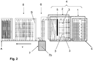
- FIG. 1 and 2 two exemplary embodiments of a continuous annealing furnace for carrying out the recrystallization annealing and embroidery are shown schematically, which differ from one another (only) in the design of the cooling device.
- the continuous annealing furnace different zones are formed between an input E and an output A, which are in the direction of passage (strip running direction v, in Figure 1 from right to left) of the steel strip S guided through the continuous annealing furnace are arranged one behind the other.
- the steel strip S running through is brought to different temperatures in order to go through the annealing cycles described above.
- a heating zone 1 follows the entrance E of the continuous annealing furnace, in which the steel strip S at least in the front area (only) by thermal radiation with a heating rate of up to 25 K / s and - depending on the selected annealing cycle - to temperatures just below or just below is heated above the Acl temperature and in particular in the range from 600 ° C to 800 ° C.
- the heating zone 1 is followed by a holding zone 2 in which the temperature of the steel strip S is kept at the holding temperature (T h ), which is below or above the Acl temperature, depending on the annealing cycle selected.
- a gassing zone 4 is formed, in which the steel strip running through is exposed to a nitrogen-containing gas.
- the aeration zone 4 has a plurality of cascades 3 of spray nozzles which are arranged one behind the other in the direction of belt travel.
- the spray nozzle cascades 3 are (only) arranged in the area of the holding zone 2. However, they can also be arranged in the area of the heating zone 1, so that the aeration zone 4 extends either only in the heating zone 1 or over the heating zone 1 and the holding zone 2.
- the spray nozzle cascades 3 are expediently arranged in the heating zone 1.
- the spray nozzle cascades 3 are expediently arranged in the holding zone 2.
- an induction or conduction heater 5 is additionally arranged in the downstream region of the holding zone 2.
- Each spray nozzle cascade 3 comprises a plurality of nozzles which are arranged at a distance from one another transversely to the strip running direction.
- the nozzles are connected to a gas supply line through which they are exposed to a nitrogen-containing gas.
- Ammonia gas has proven to be a particularly suitable gas for embroidering the steel tape. This is applied via the nozzles of the cascades 3 to the surfaces of the continuous steel strip S, where it penetrates the area of the steel strip near the surface and there - at the high temperatures in the annealing furnace - diffuses evenly into the depth of the steel strip.
- a uniformly homogeneous nitrogen distribution is therefore formed over the thickness of the steel strip, the concentration distribution of which fluctuates over the sheet thickness for steel sheets with a thickness of less than 0.4 mm by a maximum of ⁇ 10 ppm and regularly by only ⁇ 5 ppm around the mean.
- a homogeneous gassing of the surface of the steel strip in the continuous annealing furnace with the nitrogen-containing gas e.g. ammonia
- the nitrogen-containing gas e.g. ammonia
- Nitrogen can be achieved in the steel sheet, which is deposited there interstitially.
- the process of direct loading of the steel strip (gas supply) with a nitrogen-containing gas by means of nozzles has two major advantages: On the one hand, only a low nitrogen concentration (NH3 concentration) is required, which leads to a low consumption of nitrogen-containing gas (e.g. NH3 consumption) leads. On the other hand, the very short exposure time prevents the formation of a nitride layer.
- a nitrogen-containing atmosphere with a nitrogen equilibrium concentration that is as constant as possible must be maintained while the steel strip S is passed through the gassing zone 4 of the continuous annealing furnace.
- the nitrogen concentration that has developed is recorded in the area of the spray nozzle cascades 3. If ammonia is used as the nitrogen-containing gas, the ammonia concentration generated in the aeration zone 4 by the introduction of ammonia is measured for this purpose.
- a concentration sensor is provided which is arranged outside the continuous annealing furnace and which can be a laser spectroscopy sensor, for example.
- a gas sample taken from the aeration zone 4 is fed to this in order to determine the ammonia concentration and, from this, the nitrogen concentration of the gas atmosphere in the aeration zone.
- the concentration of nitrogen in the gas atmosphere of the aeration zone 4 detected by the concentration sensor is fed to a control device and used by the latter to keep the amount of nitrogen-containing gas (ammonia) sprayed into the aeration zone 4 via the nozzles of the cascades 3 constant at a predetermined target value.
- the equilibrium concentration of ammonia is preferably in the range from 0.1 to 1.0% and particularly preferably between 0.1 and 0.2%.
- These low ammonia or nitrogen concentrations in the annealing furnace are sufficient to store the desired amounts of nitrogen in the flat steel product during nitrogenization at temperatures in the range from 600 to 650 ° C. At higher temperatures, in particular above 700 ° C, such as.
- higher ammonia concentrations of up to 15% by weight must then be generated in the annealing furnace in order to achieve the desired sticking quantities.
- an inert gas is expediently introduced into the annealing furnace in addition to the nitrogen-containing gas (ammonia) in the gassing zone 4.
- nitrogen-containing gas ammonia
- It can be, for example, nitrogen gas or / or Trade hydrogen gas.
- a mixture of approx. 95% nitrogen gas and approx. 5% hydrogen gas is preferably used.
- a first cooling zone 6 In the strip running direction v after the holding zone 2 (and possibly after the induction or conduction heater 5 arranged at the end of the holding zone 2), a first cooling zone 6 is provided, in which the steel strip S running through is rapidly cooled at a cooling rate of at least 100 K / s .
- the first cooling zone 6 contains a cooling device 7, which in the embodiment of FIG Figure 1 is designed as a gas cooling device 7a, in which the steel strip is acted upon with a cold gas stream, in particular with an inert gas.
- the cooling device 7 is designed as a liquid cooling device in which the steel strip is quenched by introducing it into a cooling liquid, in particular a water bath 7b.
- the gas cooling device With the gas cooling device, cooling rates in the range from 100 to 1000 K / s can be achieved. With the liquid cooling device, significantly higher cooling rates (well above 1000 K / s) can be achieved.
- the steel strip S In the cooling device 7, which is arranged in the inert atmosphere of the annealing furnace, the steel strip S is first rapidly cooled to a temperature which is higher than room temperature, for example to temperatures around 100.degree.
- the first cooling zone 6 is advantageously followed by a second cooling zone 8 downstream, in which the steel strip S passing through is finally slowly cooled to room temperature (23 ° C.) at a cooling rate in the range of 10 to 20 K / s.
- the steel strip S is led out of the annealing furnace at exit A.
- the steel strip S is permanently located between the inlet E and the outlet A in the inert atmosphere of the annealing furnace, so that oxidation processes cannot occur on the surface of the steel strip S during the recrystallization annealing, the embroidery and the
- the steel strip S can, if necessary, still be dry-rolled (skin-passed) in order to give the strip the forming properties required for the production of packaging.
- the degree of re-rolling varies between 0.4 and 2% depending on the intended use of the packaging steel.
- the steel strip can also be wet-rolled in order to produce a further reduction in thickness of up to 43% (double reduced steel strip, "double reduced DR").
- double reduced steel strip double reduced DR
- the steel strip S is then optionally fed to a coating system in which the surface of the steel strip is coated, for example, electrolytically with a tin or a coating to increase the corrosion resistance Chromium / chromium dioxide coating (ECCS) or a paint is provided.
- ECCS Chromium / chromium dioxide coating
- the lacquer is usually burned in by heating the lacquered packaging steel, an additional increase in strength known as "lacquer aging" being observed as a result of this burn-in process. It has been shown that packaging steels produced with the method according to the invention not only have higher strengths but also better properties with regard to their corrosion resistance than the known flat steel products.
- the heat treatment according to the invention in the annealing furnace leads to the formation of a multiphase structure in the steel of the cold-rolled flat steel product.
- the structure composition can be controlled via the process parameters. It has been shown that when the flat steel product (steel strip S) is annealed above the Ac1 temperature and subsequent rapid cooling (quenching) at a cooling rate in the range from 100 K / s to approx. 1000 K / s, a multi-phase structure consisting of ferrite and Troostite (fine-striped perlite) is formed. If the flat steel product is annealed above the Ac1 temperature and then quenched at a very high cooling rate of (far) more than 1000 K / s (e.g.
- a structure is created with ferrite and martensite as essential structural components, which largely corresponds to the dual-phase structure known from body construction.
- Both the multi-phase structure made of ferrite and troostite and the multi-phase structure made of ferrite and martensite are characterized by increased strength compared to monophase steel structures.
- the high strength of the packaging steel produced according to the invention is accordingly achieved on the one hand by the strength-increasing content of unbound nitrogen interstitially deposited by the embroidery and on the other hand by the formation of a multi-phase structure during the heat treatment in the annealing furnace.
- embroidered flat steel products can be produced which are characterized by a very high strength of more than 650 MPa with good elongation at break of more than 5% and in particular between 7 and 15% and good deformation properties.
- the strength values of the packaging steel produced according to the invention are possibly determined during a baking process of an applied layer of paint even further increased (yield point increase due to paint aging, also known as "bake hardening"), with strengths of up to 850 MPa being achievable.
- the increased strength and elongation at break due to the embroidery are very homogeneous over the cross section of the steel strip, both in and across the rolling direction of the cold-rolled steel strip. This results from the very homogeneous introduction of unbound nitrogen into the steel during embroidery in the annealing furnace.
- Melt analyzes on flat steel products produced according to the invention have shown that the nitrogen concentration introduced by the embroidery over the thickness of the flat steel product, at least in the case of fine sheet metal, only fluctuates within a narrow band of at most ⁇ 10 ppm and regularly only by ⁇ 5 ppm around the mean concentration.
- the hot-rolled steel product which is used as the starting product of the process according to the invention can already contain a proportion of nitrogen.
- the following process is carried out (as an expanded exemplary embodiment of the invention): In a converter and / or in a subsequent ladle treatment, an embroidered steel melt is first produced, which has a content of free, unbound (ie dissolved in the steel) nitrogen of up to 160 ppm.
- the carbon content of the steel produced is preferably in the range from 400 to 1200 ppm and particularly preferably between 600 and 900 ppm.
- the converter is filled with scrap and pig iron and the melt is blown with oxygen gas and nitrogen gas, the oxygen gas (O2) being blown into the converter from above and nitrogen gas (N2) through bottom nozzles.
- the composition and in particular the nitrogen content of the melt is recorded. If the specified analysis has not been carried out (e.g. if the proportion of phosphorus is too high), oxygen gas is blown through an oxygen lance and argon gas (Ar) through the bottom nozzles. Since there is hardly any carbon (C) left in the steel, there is no overpressure and the nitrogen in the air is drawn in, which can lead to additional nitrogenization.
- lime nitrogen (calcium cyanamide, calcium cyanamide) can be added when emptying the converter (tapping).
- CaCN2 can be added to the steel jet emerging from the converter.
- the lime nitrogen is added, for example, in the form of granules (5-20 mm).
- the pan comes to the first argon rinse, where a refractory, immersed lance is used to rinse with argon for approx. 3 minutes. After a control analysis, it may be flushed a second time in a second argon flush for about 3 minutes. The pan then comes to a third argon sink. This represents the last stage before casting.
- manganese nitride for example in the form of a wire of MnN powder in a steel shell, can be added to the third argon sink. The amount of possibly missing nitrogen is converted into a required amount of MnN (for example into a required length of the MnN wire), which is added to the melt. The MnN is added until the specified target nitrogen content or an upper Mn limit for the steel is reached.
- the melt is poured into a tundish in order to cast a slab from the steel melt. Due to leaks and diffusion of atmospheric nitrogen, the nitrogen content can increase by approx. 10 ppm. An upper limit for the amount of dissolved nitrogen in the cast steel slab of approx. 160 ppm should not be exceeded, because defects such as cracks or pores can form on the slab at higher nitrogen contents, which lead to undesired oxidation.
- the slab cast from the steel melt is then hot-rolled and cooled to room temperature.
- the hot strip produced has thicknesses in the range of 1 up to 4 mm and is wound into a roll (coil) if necessary.
- the hot strip has to be cold-rolled, with a thickness reduction in the range from 50 to over 90%.
- thin sheet is understood to mean a sheet with a thickness of less than 3 mm and a very fine sheet has a thickness of less than 0.5 mm.
- the hot strip possibly wound up as a roll, is unwound from the roll, pickled and introduced into a cold rolling device, for example a cold rolling mill.
- the cold-rolled steel flat product already embroidered to nitrogen concentrations of up to 160 ppm is then used as the starting product for further treatment in accordance with.
- the method according to the invention in which the cold-rolled flat steel product is annealed recrystallizing in the annealing furnace and at the same time is further embroidered in order to increase the nitrogen concentration to values above 100 ppm and preferably to more than 150 ppm.
Landscapes
- Chemical & Material Sciences (AREA)
- Engineering & Computer Science (AREA)
- Mechanical Engineering (AREA)
- Materials Engineering (AREA)
- Organic Chemistry (AREA)
- Metallurgy (AREA)
- Crystallography & Structural Chemistry (AREA)
- Physics & Mathematics (AREA)
- Thermal Sciences (AREA)
- Chemical Kinetics & Catalysis (AREA)
- General Engineering & Computer Science (AREA)
- Power Engineering (AREA)
- Heat Treatment Of Sheet Steel (AREA)
- Solid-Phase Diffusion Into Metallic Material Surfaces (AREA)
- Heat Treatment Of Strip Materials And Filament Materials (AREA)
- Treatment Of Steel In Its Molten State (AREA)
Abstract
Description
- Die Erfindung betrifft ein Verfahren zur Herstellung eines aufgestickten Verpackungsstahls mit den Merkmalen des Anspruchs 1.
- Aus dem Stand der Technik ist es bekannt, die Festigkeit von Stählen durch Einbringen von ungebundenem, im Stahl gelösten Stickstoff zu erhöhen. Das Einbringen von ungebundenem Stickstoff in den Stahl wird als Aufsticken bzw. Nitrieren oder Nitridieren bezeichnet und stellt ein bekanntes Verfahren zum Härten von Stahl und Stahlprodukten dar.
- Auch das Aufsticken von Stahlflachprodukten wie Stahlbleche oder Stahlbänder, welche für die Herstellung von Verpackungen vorgesehen sind (im Folgenden als Verpackungsstahl bezeichnet), ist aus dem Stand der Technik bekannt. In der
EP 0 216 399 B1 wird beispielsweise ein Stahlblech für Verpackungszwecke sowie ein Verfahren zu dessen Herstellung beschrieben, welches aus einem aluminiumberuhigten, kontinuierlich gegossenen Kohlenstoff-Mangan-Stahl hergestellt wurde und durch Aufsticken eine Menge an ungebundenem, gelösten Stickstoff erhalten hat, wobei die Mindestmenge an ungebundenem Stickstoff in Abhängigkeit einer gewünschten Härtekategorie des Stahlblechs definiert ist und (beispielsweise für die Härtekategorie T61 des europäischen Standards 145-78) eine Menge an ungebundenem Stickstoff von wenigstens 5 ppm aufweist. Die chemische Zusammensetzung des dort offenbarten Stahlblechs entspricht bezüglich des Kohlenstoff- und Mangangehalts den üblichen weichen Stählen und weist beispielsweise einen Kohlenstoffgehalt im Bereich von 0,03 - 0,1 Gew.-% und einen Mangangehalt von 0,15 - 0,5 Gew.-% auf. Das Stahlblech zeichnet sich dabei durch eine hohe Streckgrenze im Bereich von 350 - 550 N/mm2 aus. Für die Menge an ungebundenem, im Stahl gelösten Stickstoff wird dabei ein Maximalwert von 100 ppm angegeben und damit begründet, dass das Stahlblech bei einem höheren Gehalt an ungebundenem Stickstoff aufgrund der damit verbundenen Festigkeitserhöhung nicht mehr kaltwalzbar und damit nicht für die vorgesehene Verwendung als kaltgewalzter Verpackungsstahl geeignet ist. - In dem Verfahren zur Herstellung dieses bekannten Verpackungsstahls wird zunächst ein Stahl kontinuierlich gegossen, anschließend warmgewalzt, kaltgewalzt, rekristallisierend geglüht und schließlich nachgewalzt. Nach dem Nachwalzen erfolgt eine thermische Nachbehandlung, bei der freie Versetzungen, die in dem Stahl durch das Nachwalzen gebildet werden, durch den durch das Aufsticken eingebrachten ungebundenen Stickstoff fixiert werden, um die Härte und Streckgrenze über die Werte nach dem Nachwalzen zu erhöhen. Die thermische Nachbehandlung kann dabei zweckmäßig mit einer anderen thermischen Behandlung des nachgewalzten Stahls kombiniert werden, welche im Rahmen der Herstellung eines Verpackungsstahls ohnehin durchzuführen ist, wie z.B. beim Aufschmelzen einer auf die Oberfläche des Stahlblechs elektrolytisch aufgebrachten Zinnschicht oder beim Einbrennen einer auf die Stahlblechoberfläche aufgebrachten Lackschicht.
- Wegen der in der
EP 0 216 399 B1 vorgeschlagenen Obergrenze für die Menge des ungebundenen und im Stahl gelösten Stickstoff von 100 ppm sind die Festigkeiten dieses bekannten Verpackungsstahls limitiert. Es erscheint grundsätzlich möglich, Stahlbleche mit noch höherem Gehalt an ungebundenem Stickstoff im Stahl herzustellen, um dadurch Zugfestigkeiten oberhalb von 600 MPa zu erzielen. So sind beispielsweise in derEP 1 342 798 B1 und derDE 1 433 690 A1 aufgestickte Stähle mit einem Stickstoffgehalt von bis zu 250 ppm bzw. bis zu 400 ppm beschrieben. Allerdings haben sich derart hohe Gehalte an ungebundenem Stickstoff im Stahl in der Praxis nicht realisieren lassen. - Das Aufsticken eines Stahls kann beim Herstellungsprozess des Stahls durch Einbringen von Stickstoff in die Stahlschmelze, beispielsweise durch Einblasen von Stickstoffgas N2, eingebracht werden. Ein Verfahren zum Aufsticken von Stahlschmelzen bei der Stahlherstellung im Sauerstoffaufblasverfahren ist beispielsweise in der
DE 2 237 498 beschrieben. Stahlflachprodukte, insbesondere Stahlbänder, können durch eine Oberflächenkonditionierung aufgestickt werden, beispielsweise durch Eindiffusion von Stickstoff in die Stahlblechoberfläche, was beispielsweise durch Gasnitrieren in einer Ammoniak-Atmosphäre bei leichtem Überdruck, durch Badnitrieren in stickstoffhaltigen Salzbädern oder durch Plasmanitrieren erfolgen kann. Durch Eindiffusion von Stickstoff bildet sich an der Stahlblechoberfläche dabei eine harte, oberflächliche Verbindungsschicht sowie eine darunter liegende Diffusionszone aus, in welcher der Stickstoff bis zu einer bestimmten Tiefe in der (ferritischen) Stahlmatrix eingelagert ist. - Die Aufgabe der Erfindung besteht darin, ein Stahlflachprodukt (Stahlblech oder Stahlband) für die Herstellung von Verpackungen aufzuzeigen, welches eine möglichst hohe Festigkeit bei gleichzeitig guter Bruchdehnung und guten Umformeigenschaften aufweist. Insbesondere soll ein Verpackungsstahl mit Festigkeiten von wenigstens 600 MPa bei einer Bruchdehnung von wenigstens 5 % zur Verfügung gestellt werden. Der höherfeste Verpackungsstahl muss dabei für den vorgesehenen Verwendungszweck als Verpackungsstahl gleichzeitig eine ausreichende Umformfähigkeit aufweisen, beispielsweise in Tiefzieh- oder Abstreckziehverfahren, damit aus dem Stahlflachprodukt bestimmungsgemäß Verpackungen, wie z.B. Konserven- oder Getränkedosen, hergestellt werden können. Der als Stahlflachprodukt vorliegende Verpackungsstahl soll dabei die üblichen Dicken im Fein- und Feinstblechbereich aufweisen, welche üblicherweise im Bereich von 0,1 bis 0,5 mm (Feinstblech) bzw. 0,5 bis 3 mm (Feinblech) liegen und durch Kaltwalzen erzeugt werden.
- Diese Aufgaben werden mit einem Verfahren mit den Merkmalen des Anspruchs 1 gelöst. Bevorzugte Ausführungsformen des erfindungsgemäßen Verfahrens sind in den abhängigen Ansprüchen aufgezeigt.
- Mit dem erfindungsgemäßen Verfahren kann ein aufgestickter Verpackungsstahl mit einem Kohlenstoffgehalt von 400 bis 1200 ppm und einer Menge von ungebundenem, im Stahl gelösten Stickstoff von mehr als 100 ppm und bevorzugt von mehr als 150 ppm und besonders bevorzugt von mehr als 210 ppm hergestellt werden, wobei zunächst ein warmgewalztes und ggf. bereits aufgesticktes Stahlprodukt zu einem Stahlflachprodukt kaltgewalzt wird, das kaltgewalzte Stahlflachprodukt danach in einem Glühofen rekristallisierend geglüht wird, wobei in den Glühofen ein stickstoffhaltiges Gas eingeleitet und auf das Stahlflachprodukt gerichtet wird, um ungebundenen Stickstoff in das Stahlflachprodukt in einer Menge entsprechend einer Konzentration von mehr als 100 ppm einzubringen oder die Menge von ungebundenem Stickstoff im Stahlflachprodukt auf eine Konzentration von mehr als 100 ppm zu erhöhen. Unmittelbar nach dem Glühen wird das Stahlflachprodukt mit einer Kühlrate von wenigstens 100 K/s abgekühlt.
- Dabei wird das kaltgewalzte Stahlflachprodukt in dem Glühofen zunächst in einem ersten Erhitzungsschritt auf eine Haltetemperatur (Th) unterhalb der Acl-Temperatur und insbesondere im Bereich von 600°C bis 650°C erhitzt und in einem anschließenden Halteschritt auf dieser Haltetemperatur (Th) gehalten, um das kaltgewalzte Stahlflachprodukt bei der Haltetemperatur (Th) zum Aufsticken mit dem stickstoffhaltigen Gas zu beaufschlagen. Alternativ wird das kaltgewalzte Stahlflachprodukt in dem Glühofen zunächst in einem Erhitzungsschritt auf eine Haltetemperatur (Th) oberhalb der Acl-Temperatur und insbesondere im Bereich von 740°C bis 760°C erhitzt und in einem anschließenden Halteschritt auf dieser Haltetemperatur (Th) gehalten, wobei das kaltgewalzte Stahlflachprodukt während des Erhitzungsschritts und/oder während des Halteschritts zum Aufsticken mit dem stickstoffhaltigen Gas beaufschlagt wird.
- Durch diese Verfahrensführung wird einerseits ein mehrphasiges Gefüge in dem Stahlflachprodukt ausgebildet, welches Ferrit und mindestens einen der Gefügebestandteile Martensit, Bainit, Troostit/Perlit und/oder Restaustenit umfasst. Stahlprodukte mit einem derartigen Gefüge weisen gegenüber monophasigen Stählen eine erhöhte Festigkeit auf. Anderseits wird durch das Aufsticken des Stahlflachprodukts während des rekristallisierenden Glühens die Stickstoffkonzentration im Stahl auf Wertebereiche (von mehr als 100 ppm) erhöht, welche ebenfalls eine Festigkeitssteigerung bewirken.
- Es hat sich gezeigt, dass für die Ausbildung eines mehrphasigen Gefüges der Kohlenstoffgehalt des Stahls mindestens 0,04 Gew.% betragen sollte. Die obere Grenze des Kohlenstoffgehalts ist einerseits durch die von den Normen für Verpackungsstahl geforderten Obergrenzen von ca. 0,12 Gew.% (wie im Standard ASTM A623-11 definiert) und andererseits technologisch durch die Kaltwalzbarkeit vorgegeben, wobei erfahrungsgemäß ein warmgewalztes Stahlprodukt mit mehr als 0,12 Gew.% Kohlenstoffgehalt nur sehr schwer kaltgewalzt werden kann.
- Das Aufsticken des Stahls kann dabei zweckmäßig in zwei Stufen erfolgen. In einer ersten Stufe wird eine Stahlschmelze auf einen Stickstoffgehalt von maximal 160 ppm nitriert, indem der Stahlschmelze Stickstoff, beispielsweise in Form eines stickstoffhaltigen Gas und/oder eines stickstoffhaltigen Feststoffs, zugeführt wird. Aus der so aufgestickten Stahlschmelze wird eine Bramme gegossen und zu einem Warmband warmgewalzt. Das Warmband wird anschließend (nach Abkühlung auf Umgebungstemperatur) erforderlichenfalls gebeizt und zu einem Stahlflachprodukt (Stahlblech oder Stahlband) kaltgewalzt. Das kaltgewalzte Stahlflachprodukt wird danach in dem Glühofen rekristallisierend geglüht. In dem Glühofen wird dabei die zweite Stufe des Aufstickens durchgeführt, indem in den Glühofen ein stickstoffhaltiges Gas eingeleitet und auf das Stahlflachprodukt gerichtet wird, um die Menge an ungebundenem Stickstoff im Stahl über die bereits in der ersten Stufe des Aufstickens in die Stahlschmelze eingebrachte Stickstoffmenge hinaus weiter zu erhöhen.
- Durch das zweistufige Aufsticken des Verpackungsstahls wird gewährleistet, dass das Warmband mit den üblicherweise für die Herstellung von Verpackungsstählen verwendeten Kaltwalzvorrichtungen (Walzstraßen) problemlos zu einem Stahlflachprodukt, insbesondere zu einem Stahlband, kaltgewalzt werden kann. Dies wird dadurch ermöglicht, dass in der ersten Stufe des Aufstickens ein Gehalt an ungebundenem Stickstoff von höchstens 160 ppm in die Stahlschmelze eingebracht wird. Das aus der aufgestickten Stahlschmelze durch Warmwalzen erzeugte Warmband bleibt bei diesen Stickstoffgehalten kaltwalzbar, so dass aus dem Warmband durch Kaltwalzen ein Fein- oder Feinstblech in den für Verpackungszwecke üblichen Dicken herstellbar ist. Höhere Stickstoffgehalte in der Stahlschmelze führen darüber hinaus auch zu unerwünschten Defekten in der aus der Stahlschmelze gegossenen Bramme. Die gewünschte Festigkeit des Verpackungsstahls von bevorzugt mehr als 600 MPa wird beim Kaltwalzen und in der zweiten Stufe des Aufstickens des Stahlflachprodukts während seines rekristallisierenden Glühens erzielt. Dadurch können Stahlflachprodukte, insbesondere Stahlbänder, mit Dicken im Fein- und Feinstblechbereich, insbesondere im Bereich von 0,1 bis 0,5 mm, zur Verwendung als Verpackungsstahl mit sehr hohen Zugfestigkeiten bei gleichzeitig hoher Bruchdehnung von bevorzugt wenigstens 5 % hergestellt werden, ohne eine Beschränkung in den Umformeigenschaften zu erleiden.
- In bevorzugten Ausführungsbeispielen des erfindungsgemäßen Verfahrens erfolgt das Aufsticken der Stahlschmelze in der ersten Stufe durch Einleiten von Stickstoffgas (N2) und/oder Kalkstickstoff (CaCN2) und/oder Manganstickstoff (MnN) in die Stahlschmelze.
- Das Aufsticken des Stahlflachprodukts in der zweiten Stufe erfolgt bevorzugt durch Einleiten von Ammoniakgas (NH3) in den Glühofen, in dem das Stahlflachprodukt rekristallisierend geglüht wird. Zweckmäßig wird das Ammoniakgas dabei mittels Sprühdüsen auf die Oberfläche des Stahlflachprodukts aufgegast. Die Menge an Ammoniakgas, die in den Glühofen eingebracht wird, wird bevorzugt so eingestellt, dass sich in dem Glühofen ein Ammoniakgleichgewicht mit einer Ammoniakkonzentration im Bereich von 0,05 bis 15 % einstellt (in Gew.%, bezogen auf die Gasatmosphäre im Glühofen). Die für ein effektives Aufsticken erforderliche Ammoniakkonzentration in dem Glühofen hängt dabei von der Temperatur im Glühofen ab. Bei idealen Temperaturen im Bereich von 600 bis 650°C reichen bereits Ammoniakkonzentration im Bereich von 0,05 bis 1,5 Gew.% aus, um beim Aufsticken die gewünschten Mengen an ungebundenem Stickstoff (interstitiell) im Stahlflachprodukt einzulagern. Bei höheren Temperaturen, insbesondere oberhalb von 700°C muss die Ammoniakkonzentration im Glühofen entsprechen höher (bis zu 15 Gew.%) gewählt werden, um Stickstoff in nennenswerten Mengen im Stahlflachprodukt einzulagern. Die Ammoniakkonzentration in dem Glühofen wird bevorzugt mittels eines Ammoniaksensors erfasst und der erfasste Messwert der Ammoniak-Gleichgewichtskonzentration wird für eine Regelung der pro Zeiteinheit in den Glühofen eingeleiteten Menge an Ammoniakgas verwendet. Dadurch kann eine gleichbleibende Ammoniakgas-Konzentration in dem Glühofen und damit eine homogene Aufstickung des Stahlflachprodukts mit über die Produktionszeit eines Stahlbands gleichbleibender Qualität und homogener Stickstoffkonzentration über die Länge des Stahlbands gewährleistet werden.
- Zur Vermeidung von Oxidationsprozessen wird beim rekristallisierenden Glühen in dem Glühofen neben dem Ammoniakgas, welches zum Aufsticken verwendet wird, noch ein Inertgas in den Glühofen eingeleitet, beispielsweise Stickstoffgas und/oder Wasserstoffgas oder ein Gemisch davon, beispielsweise in einer Zusammensetzung von 95 Gew.-% Stickstoffgas und 5 Gew.-% Wasserstoffgas. Der Glühofen wirkt dadurch auch als abgeschlossene Inertkammer. Das durch den Glühofen durchgeführte Stahlband kommt deshalb beim rekristallisierenden Glühen und Aufsticken bis zur Abkühlung nicht mit einer oxidierenden Umgebung und insbesondere nicht mit Luftsauerstoff in Berührung, weshalb eine Ausbildung von Oxidschichten an der Oberfläche des Stahlbands vermieden werden können.
- Die durch das zweistufige Aufsticken des Verpackungsstahls eingebrachten Gesamtmengen an ungebundenem Stickstoff liegen zwischen 100 und 500 ppm, bevorzugt oberhalb von 150 ppm und besonders bevorzugt im Bereich zwischen 210 und 350 ppm. Dabei wird bei einer zweistufigen Aufstickung in der ersten Stufe beim Aufsticken der Stahlschmelze ein Stickstoffgehalt von maximal 160 ppm in die Stahlschmelze eingebracht. Das Einhalten einer Obergrenze von ca. 160 ppm für den Gehalt an ungebundenem Stickstoff in der Stahlschmelze stellt dabei sicher, dass an der aus der Stahlschmelze erzeugten Bramme keine Defekte entstehen, beispielsweise in Form von Poren und Risse, welche durch Umgebungssauerstoff oxidieren können. Weiterhin bleibt das aus der Bramme erzeugte Warmband bei einem Stickstoffgehalt von höchstens 160 ppm kaltwalzbar. Alternativ hierzu kann das Aufsticken auch einstufig erfolgen, wobei dann nur ein Aufsticken des kaltgewalzten Stahlflachprodukts durch Beaufschlagung mit einem stickstoffhaltigen Gas im Durchlaufofen während des rekristallisierenden Glühens erfolgt.
- Die (ggf. als zweite Stufe) beim Aufsticken des Stahlflachprodukts im Glühofen durch Beaufschlagung mit einem stickstoffhaltigen Gas (ggf. zusätzlich) einbringbare Menge an ungebundenem Stickstoff liegt im Bereich von 100 bis 350 ppm. Bei Anwendung der beiden Aufstick-Stufen kann damit eine Gesamtmenge an ungebundenem Stickstoff in den erfindungsgemäß hergestellten Verpackungsstahl von bevorzugt mehr als 150 ppm und besonders bevorzugt von mehr als 210 ppm und bis zu 500 ppm eingebracht werden. Dadurch lassen sich Zugfestigkeiten von mehr als 650 MPa und bis zu 1000 MPa erzielen, wobei zwischen dem Gehalt an ungebundenem Stickstoff und der Zugfestigkeit ein linearer Zusammenhang fest gestellt worden ist und bspw. für Zugfestigkeiten von ca. 650 MPa ein Gehalt an ungebundenem Stickstoff von ca. 210 ppm erforderlich ist.
- Zur Erhöhung der Festigkeit des kaltgewalzten Stahlflachprodukts trägt neben dem Aufsticken das durch die erfindungsgemäße Wärmebehandlung erzeugte mehrphasige Gefüge des Stahls bei. Zur Ausbildung eines mehrphasigen Gefüges wird das kaltgewalzte Stahlflachprodukts beim rekristallisierenden Glühen in einem Erhitzungsschritt auf Temperaturen oberhalb der Acl-Temperatur (welche bei der verwendeten Legierungskomposition des Stahls in der Regel bei ca. 723°C liegt) erhitzt. Es hat sich gezeigt, dass es zur Ausbildung eines mehrphasigen Gefüges erforderlich ist, das Stahlflachprodukt zumindest kurzzeitig auf eine Temperatur oberhalb der Acl-Temperatur zu erhitzen. Das Erhitzen kann dabei entweder durch Wärmestrahlung im Glühofen oder auch induktiv oder konduktiv erfolgent, wobei über eine induktive oder konduktive Erhitzung sehr hohe Aufheizraten von mehr als 500 K/s erreicht werden können. Beim Erhitzen des kaltgewalzten Stahlflachprodukts wird dieses für eine ausreichend lange Erhitzungsdauer auf Temperaturen oberhalb der Rekristallisations-Temperatur gehalten, um das Stahlflachprodukt rekristallisierend zu glühen, wodurch die Umformfähigkeit des kaltgewalzten Stahlflachprodukts wieder hergestellt wird. Nach dem (zumindest kurzzeitigen) Erhitzen auf Temperaturen oberhalb der Acl-Temperatur wird das Stahlflachprodukt schnell abgekühlt, wobei eine Kühlrate von wenigstens 100 K/s und bevorzugt von mehr als 150 K/s einzuhalten ist, um in dem Stahl ein mehrphasiges Gefüge auszubilden.
- Um in dem Glühofen sowohl für das rekristallisierende Glühen und die Ausbildung eines mehrphasigen Gefüges als auch für das Aufsticken optimale thermische Bedingen zu gewährleisten, wird das Stahlflachprodukt in dem Glühofen zweckmäßig einem Glühzyklus mit vorgegebenen Temperaturprofilen unterworfen. In einem ersten Ausführungsbeispiel für einen solchen Glühzyklus gemäß der Erfindung wird das kaltgewalzte Stahlflachprodukts in einem Durchlaufglühofen (durch Wärmestrahlung) in einem ersten Erhitzungsschritt zunächst von Umgebungstemperatur mit einer Aufheizrate von zweckmäßig 15 bis 25 K/s und insbesondere von 20 K/s auf eine Haltetemperatur oberhalb der Rekristallisationstemperatur aber noch unterhalb der Acl-Temperatur und insbesondere im Bereich von 600°C bis 650°C, erhitzt und dann über einen Haltezeitraum auf dieser Haltetemperatur (Th) gehalten. Während des Haltezeitraums, der zweckmäßig im Bereich von 80 bis 150 Sekunden und bspw. bei ca. 100 bis 110 Sekunden liegt, wird das Stahlflachprodukt bei der Haltetemperatur (Th) zum Aufsticken mit dem stickstoffhaltigen Gas beaufschlagt. Zweckmäßig wird dabei die Haltetemperatur (Th) so ausgewählt, dass eine möglichst effiziente Einlagerung von Stickstoff in das Stahlflachprodukt gewährleistet werden kann, Es hat sich gezeigt, dass dies insbesondere im Temperaturbereich zwischen 600°C und 650°C der Fall ist. Die AmmoniacKonzentration im Glühofen kann dabei auf niedrige Werte im Bereich von 0,05 bis 1,5 Gew.% eingestellt werden.
- Unmittelbar nach dem Aufsticken im Glühofen wird das Stahlflachprodukt in einem zweiten Erhitzungsschritt auf eine Glühtemperatur (Tg) oberhalb der Acl-Temperatur undbevorzugt zwischen 740°C ≤ Tg ≤ 760°C erhitzt und anschließend mit einer Kühlrate von mehr als 100 K/s abgekühlt. Die Aufheizrate in dem zweiten Erhitzungsschritt beträgt dabei bevorzugt mehr als 100 K/s und besonders bevorzugt mehr als 500 K/s, wobei das Erhitzen in dem zweiten Erhitzungsschritt zur Erzielung solch hoher Aufheizraten dabei zweckmäßig induktiv oder konduktiv erfolgt. Mittels induktiver oder konduktiver Erhitzung können Aufheizraten von über 1000 K/s erzielt werden.
- Das Abkühlen mit der bevorzugten Kühlrate von mehr als 100 K/s kann entweder mittels eines kalten Gasstroms (bevorzugt eines Inertgases wie Wasserstoff oder Stickstoff) oder durch Einleiten des Stahlflachprodukts in eine Abschreckflüssigkeit (bspw. einen Wassertank) erfolgen, wobei das Stahlflachprodukt bevorzugt auf Umgebungstemperatur abgekühlt wird. In einem zweiten Ausführungsbeispiel für einen Glühzyklus gemäß der Erfindung wird das kaltgewalzte Stahlflachprodukts in einem Durchlaufglühofen (durch Wärmestrahlung) in einem (einzigen) Erhitzungsschritt zunächst von Umgebungstemperatur mit einer Aufheizrate von zweckmäßig mehr als15 K/s auf eine Haltetemperatur (Th) oberhalb der Acl-Temperatur und insbesondere im Bereich von 740°C bis 760°C erhitzt und in einem anschließenden Halteschritt über eine Haltezeit auf dieser Haltetemperatur (Th) gehalten, wobei das kaltgewalzte Stahlflachprodukt während des Erhitzungsschritts und/oder während des Halteschritts zum Aufsticken mit dem stickstoffhaltigen Gas beaufschlagt wird. Bevorzugt wird das Stahlflachprodukt während des Erhitzungsschritts mit dem stickstoffhaltigen Gas beaufschlagt, da sich gezeigt hat, dass die Aufstickung bei Temperaturen unterhalb von ca. 700°C und insbesondere im Temperaturbereich von 600°C bis 660°C am effizientesten ist. Die Haltezeit, während derer das Stahlflachprodukt auf Temperaturen oberhalb der Ac1-Temperatur gehalten wird, liegt dabei zweckmäßig im Bereich von 80 bis 150 Sekunden und bspw. bei ca. 100 - 110 Sekunden.
- Zum Aufsticken des Stahlflachprodukts in dem Glühofen wird bevorzugt eine Mehrzahl von Sprühdüsen verwendet, mit denen ein stickstoffhaltiges Gas, wie z.B. Ammoniakgas, gleichförmig auf die Oberfläche des durch den Glühofen laufenden Stahlflachprodukts aufgebracht werden kann. Bei Herstellung eines Stahlbands, welches mit einer Bandgeschwindigkeit von wenigstens 200 m/min durch den Glühofen geleitet wird, werden die mehreren Sprühdüsen bspw. quer zur Bandlaufrichtung und bevorzugt in äquidistantem Abstand zueinander angeordnet. Dadurch ist eine homogene Aufstickung des Stahlflachprodukts über die gesamte Oberfläche möglich.
- Durch die Erfassung der Konzentration des in den Glühofen eingebrachten stickstoffhaltigen Gases kann sichergestellt werden, dass während des Durchlaufens des Stahlbands durch den Glühofen eine gleichbleibende Stickstoffatmosphäre im Glühofen aufrechterhalten wird. Dies ermöglicht ein homogenes Aufsticken des Stahlbands über dessen Länge.
- Durch Vergleichsversuche konnte festgestellt werden, dass durch das Aufsticken des erfindungsgemäß hergestellten Verpackungsstahls nicht nur dessen Festigkeit erhöht werden kann, sondern dass zusätzlich durch den höheren Gehalt an ungebundenem Stickstoff in dem Stahl eine verbesserte Umformbarkeit zu beobachten ist. Dies zeigt sich insbesondere bei erfindungsgemäß hergestellten Verpackungsstählen, welche mit einem Lack beschichtet werden. Bei herkömmlich lackbeschichteten Verpackungsstählen ist nach einer beim Lackieren zum Einbrennen erforderlichen Wärmebehandlung eine sprunghafte Reduzierung der Bruchdehnung des Stahlflachprodukts bei höheren Festigkeiten zu beobachten. Dieses Phänomen kann bei den erfindungsgemäß hergestellten aufgestickten Stahlflachprodukten nicht beobachtet werden. Hier wird auch bei sehr hohen Festigkeiten von mehr als 650 MPa nach einer Wärmebehandlung beim Lackieren (Lackalterung) keine Reduktion der Bruchdehnung beobachtet. Dies kann möglicherweise dadurch erklärt werden, dass der durch das zweistufige Aufsticken vorhandene hohe Gehalt an ungebundenem Stickstoff und die sehr homogene Verteilung des Stickstoffs in dem Stahl vorhandene Versetzungen zunächst blockiert und diese durch freie Stickstoffatome blockierten Versetzungen bei einer Verformung des Stahlflachprodukts plötzlich in großer Zahl gelöst werden, sobald eine angelegte Zugspannung über einen Grenzwert hinaus erhöht wird. Dadurch können die vielen, durch die Verformung von einer Stickstoffblockade freigesetzten Versetzungen im Stahl wandern, wodurch die Umformbarkeit verbessert wird.
- Diese und weitere Vorteile des erfindungsgemäß hergestellten Verpackungsstahls ergeben sich aus dem nachfolgend unter Bezugnahme auf die begleitenden Zeichnungen näher beschriebenen Ausführungsbeispiel. Die Zeichnungen zeigen:
- Figur 1:
- schematische Darstellung eines ersten Ausführungsbeispiels eines Glühofens, in dem die Aufstickung und das rekristallisierende Glühen eines Stahlflachprodukts gemäß dem erfindungsgemäßen Verfahren durchgeführt wird;
- Figur 2:
- schematische Darstellung eines zweiten Ausführungsbeispiels eines Glühofens, in dem die Aufstickung und das rekristallisierende Glühen eines Stahlflachprodukts gemäß dem erfindungsgemäßen Verfahren durchgeführt wird;
- Figur 3:
- graphische Darstellung des zeitlichen Temperaturverlaufs von in dem Glühofen von
Figur 1 bei der Durchführung des erfindungsgemäßen Verfahrens durchgeführten Glühzyklen. - In einem ersten Ausführungsbeispiel des erfindungsgemäßen Verfahrens wird als Ausgangsprodukt ein im Stranggießen gefertigtes und warmgewalztes Stahlprodukt mit einer Dicke im Bereich von 2 bis 15 mm Dicke und mit einem Kohlenstoffgehalt von 400 bis 1200 ppm verwendet. Die Legierungszusammensetzung des Stahls erfüllt dabei zweckmäßig die durch Normen für Verpackungsstahl vorgegebenen Grenzwerte (wie z.B. in der Norm ASTM A623-11 "Standard Specification for Tin Mill Products" oder im "European Standard EN 10202" definiert). Bevorzugt weist das als Ausgangsprodukt verwendete Stahlprodukt folgende Obergrenzen für den Gewichtsanteil der Legierungsbestandteile auf (um das Endprodukt in Einklang mit den zitierten Normen für Verpackungsstahl zu bringen):
- C: max. 0,12 %, - Mn: max. 0,4 %, - Si: max. 0,04 %, bevorzugt weniger als 0,02 %; - Al: max. 0,1 %, bevorzugt weniger als 0,08 %; - Cr: max. 0,1 %, bevorzugt weniger als 0,08 %; - P: max. 0,03 %, bevorzugt weniger als 0,02 %; - Cu: max. 0,1 %, bevorzugt weniger als 0,08 %; - Ni: max. 0,15 %, bevorzugt weniger als 0,08 %; - Sn: max. 0,04 %, bevorzugt weniger als 0,02 %; - As: max. 0,02 %, - S: max. 0,03%, bevorzugt weniger als 0,02 %; - Mo: max. 0,05 %, bevorzugt weniger als 0,02 %; - V: max. 0,04 %; - Ti: max. 0,05 %, bevorzugt weniger als 0,02 %; - Nb: max. 0,05 %, bevorzugt weniger als 0,02 %; - B: max. 0,005 % - andere Legierungsbestandteile, einschl. Verunreinigungen: max. 0,05 %, - Rest Eisen. - Ein Stahlprodukt mit einer solchen Legierungszusammensetzung wird in dem erfindungsgemäßen Verfahren zunächst unter einer Dickenreduktion von 50% bis 96% bis zu einer Enddicke im Fein- oder Feinstblechbereich (ca. 0,1 bis 0,5 mm) zu einem Stahlflachprodukt (Stahlblech oder Stahlband) kaltgewalzt. Zweckmäßig wird das Stahlprodukt zu einem Stahlband gewalzt und als Rolle (coil) aufgewickelt. Gemäß der Erfindung wird das Stahlflachprodukt danach in einen Glühofen geführt, um es einerseits rekristallisierend zu glühen und andererseits auf Stickstoffkonzentrationen von mehr als 100 ppm und bevorzugt von mehr als 210 ppm aufzusticken. Unmittelbar nach dem rekristallisierenden Glühen wird das Stahlflachprodukt erfindungsgemäß mit einer Kühlrate von wenigstens 100 K/s zweckmäßig auf Raumtemperatur abgekühlt.
- Zur Wiederherstellung des beim Kaltwalzen des Stahlprodukts zerstörten Kristallgefüges des Stahls muss das kaltgewalzte Stahlband rekristallisierend geglüht werden. Dies erfolgt gemäß der Erfindung durch Durchleiten des kaltgewalzten Stahlbands durch einen Glühofen, der zweckmäßig als Durchlaufglühofen ausgebildet ist, durch den das hierfür zweckmäßig als Stahlband vorliegende Stahlflachprodukt mit einer Geschwindigkeit von mehr als 200 m/min durchgeführt wird. In dem Glühofen wird das im Folgenden als Stahlband bezeichnete Stahlflachprodukt auf Temperaturen oberhalb des Rekristallisationspunkts des Stahls und zumindest kurzzeitig oberhalb der Acl-Temperatur erhitzt. In dem erfindungsgemäßen Verfahren erfolgt gleichzeitig mit dem Rekristallisationsglühen ein Aufsticken des Stahlbands. Dies wird ebenfalls in dem Glühofen durchgeführt, indem in den Glühofen ein stickstoffhaltiges Gas, bevorzugt Ammoniak (NH3) eingebracht und auf die Oberfläche des Stahlbands geleitet wird. Um in dem Glühofen sowohl für das Rekristallisationsglühen als auch für das Aufsticken optimale (Temperatur-) Bedingungen zu schaffen, wird das Stahlband in dem Glühofen einem Glühzyklus (Glühprozess mit zeitlich wechselndem Temperaturverlauf des Stahlbands) unterworfen. Die Glühzyklen gemäß der Erfindung werden nachfolgend unter Bezugnahme auf
Figur 3 erläutert:
InFigur 3 (a) ist ein erstes Ausführungsbeispiel für einen geeigneten Glühzyklus gemäß der Erfindung in Form des zeitlichen Verlaufs der Temperatur (T) des durch den Glühofen geführten Stahlbands dargestellt. Das Stahlband wird bei diesem Glühzyklus in dem Glühofen zunächst in einem ersten Erhitzungsschritt I von Raumtemperatur auf eine Haltetemperatur (Th) erhitzt. Die Erhitzung des Stahlbands in dem ersten Erhitzungsschritt erfolgt dabei durch Wärmestrahlung in dem aufgeheizten Glühofen mit einer (vergleichsweise geringen) Aufheizrate von 15 bis 25 K/s und insbesondere von ca. 20 K/s. Die Haltetemperatur (Th) liegt dabei zweckmäßig knapp oberhalb der Rekristallisationstemperatur des Stahls und bevorzugt im Bereich von 600°C bis 650°C. Die Temperatur des Stahlbands wird in einem sich an den ersten Erhitzungsschritt I anschließenden Halteschritt II auf der Haltetemperatur (Th) über eine erste Haltezeit (th1) von ca. 60 bis 200 Sekunden und bevorzugt von 80 bis 150 Sekunden, insbesondere von ca. 100 bis 110 Sekunden, gehalten. Während des Halteschritts II wird das Stahlband in einer Aufstickphase A, bevorzugt über die gesamte Haltezeit (th1), mit einem stickstoffhaltigen Gas beaufschlagt, um das Stahlband aufzusticken (d.h. die Konzentration von ungebundenem Stickstoff im Stahl auf Werte oberhalb von 100 ppm und bevorzugt von mehr als 210 ppm zu erhöhen). Nach Beendigung der ersten Haltezeit (th1) wird das Stahlband in einem zweiten (kurzen) Erhitzungsschritt III sehr schnell (bevorzugt innerhalb einer kurzen Aufheizzeit zwischen ca. 0,1 s und 10), mit einer Aufheizrate von mehr als 100 K/s und bevorzugt von mehr als 500 K/s auf eine Temperatur oberhalb der Ac1-Temperatur des Stahls erhitzt, insbesondere auf Temperaturen im Bereich von 725°C bis 800°C. Der zweite Erhitzungsschritt III wird dabei innerhalb des Glühofens durch induktives oder konduktives Erhitzen des Stahlbands durchgeführt. Hierfür ist innerhalb des Glühofens eine Induktions- oder eine Konduktionsheizung angeordnet, durch welche das Stahlband in dem zweiten Erhitzungsschritt III geführt wird.An den zweiten Erhitzungsschritt III schließt sich ein kurzer zweiter Halteschritt IV an, in dem das Stahlband durch die Induktions- oder eine Konduktionsheizung geführt und seine Temperatur über eine (kurze) zweite Haltezeit (th2), welche im Bereich von wenigen Sekunden (bspw. zwischen 0,1 und 10 Sekunden und insbesondere bei ca. 2 Sekunden) liegt, oberhalb der Acl-Temperatur gehalten wird. - Nach dem Glühen wird das Stahlband aus dem Glühofen herausgeführt und in einem Kühlschritt V außerhalb des Glühofens mit einer Kühlrate von wenigstens 100 K/s auf Raumtemperatur abgekühlt. Der Kühlschritt V schließt sich dabei unmittelbar an die (kurze) zweite Haltezeit (th2) an. Die Abkühlung kann dabei bspw. mittels eines kalten Gasstroms erfolgen, der auf die Oberfläche des Stahlbands gerichtet wird, oder durch Einleiten des Stahlbands in eine Kühlflüssigkeit, bspw. in ein Wasserbad. Bei Verwendung einer Kühlflüssigkeit können höhere Kühlraten im Bereich von >> 1000 K/s erzielt werden. Das Abschrecken des Stahlbands mit einer Kühlflüssigkeit ist allerdings apparativ aufwendiger.
- Das zumindest kurzzeitige Erhitzen des Stahlflachprodukts auf Temperaturen oberhalb der Acl-Temperatur (ca. 723°C) gewährleistet bei dem Glühzyklus der
Figur 3a , dass der Stahl in das 2-Phasengebiet kommt (alpha- und gamma-Eisen), was wiederum beim anschließenden (schnellen) Abkühlen ermöglicht, ein Mehrphasengefüge auszubilden. Gleichzeitig kann das Aufsticken in diesem Glühzyklus während des ersten Halteschritts II bei wesentlichen niedrigeren Temperaturen (im Bereich von 600°C bis 650°C) aufgestickt werden, was eine höhere Effizienz des Aufstickens und einen niedrigeren Verbrauch an stickstoffhaltigem Gas ermöglicht. - In den
Figuren 3 (b) und3 (c) sind zwei weitere Ausführungsbeispiele für geeignete Glühzyklen gemäß der Erfindung dargestellt. Bei diesen Glühzyklen wird das Stahlband in dem Glühofen zunächst in einem (einzigen) Erhitzungsschritt I von Raumtemperatur auf eine Haltetemperatur (Th) erhitzt, wobei die Haltetemperatur (Th) - anders beim ersten Ausführungsbeispiel vonFigur 3 (a) - dabei oberhalb der Acl-Temperatur des Stahls liegt und bevorzugt im Bereich von 740°C bis 800°C ist. Die Erhitzung des Stahlbands in dem (einzigen) Erhitzungsschritt I erfolgt dabei wiederum durch Wärmestrahlung in dem aufgeheizten Glühofen mit einer (vergleichsweise geringen) Aufheizrate von 15 bis 25 K/s und insbesondere von ca. 20 K/s. Die Temperatur des Stahlbands wird in einem sich an den (einzigen) Erhitzungsschritt I anschließenden Halteschritt II auf der Haltetemperatur (Th > Ac1) über eine Haltezeit (th1) von ca. 60 bis 200 Sekunden und bevorzugt von 80 bis 150 Sekunden gehalten. Anschließend wird das Stahlband - wie beim Ausführungsbeispiel vonFigur 3 (a) - in dem Glühofen in einem Kühlschritt V mit einer Kühlrate von wenigstens 100 K/s auf Raumtemperatur abgekühlt. Der Kühlschritt V schließt sich dabei unmittelbar an den Halteschritt II an. - In dem Glühzyklus gem.
Figur 3 (b) wird das Stahlband bereits während des (einzigen) Erhitzungsschritt I mit einem stichstoffhaltigen Gas beaufschlagt. Die Aufstickphase A fällt bei diesem Glühzyklus also mit der Erhitzung des Stahlbands im (einzigen) Erhitzungsschritt I zusammen. Bevorzugt wird das Stahlband zumindest im Wesentlichen über die gesamte Aufheizzeit des Erhitzungsschritts I mit einem stickstoffhaltigen Gas beaufschlagt, um das Stahlband aufzusticken. - Im Gegensatz dazu wird das Stahlband in dem Glühzyklus gem.
Figur 3 (c) erst während des Halteschritts II mit einem stichstoffhaltigen Gas beaufschlagt. Die Aufstickphase A fällt bei diesem Glühzyklus also mit dem Halteschritt II zusammen. - Es hat sich gezeigt, dass es vorteilhaft ist, im Anschluss an die Begasung mit einem stickstoffhaltigen Gas (bspw. NH3-Behandlung) das Stahlband über eine Haltezeit von bevorzugt mehr als 5 Sekunden auf Temperaturen oberhalb von 600 °C zu halten, bevor es abgekühlt wird. Dadurch kommt es zu einer Homogenisierung der Stickstoffverteilung über den Querschnitt des Stahlbands und dadurch zu verbesserten Umformeigenschaften des Stahlbands. Insbesondere kann dadurch auch ein Dehnungsabfall bei einer Lackalterung vermieden werden. Deshalb werden die Glühzyklen gem. den
Figuren 3 (a) und3 (b) bevorzugt, und im Glühzyklus gemäßFigur 3 (c) wird die Aufstickphase zweckmäßig vor dem Ende der Haltezeit beendet. - In den
Figuren 1 und2 sind schematisch zwei Ausführungsbeispiele eines Durchlaufglühofens zur Durchführung des Rekristallisationsglühens und des Aufstickens gezeigt, welche sich (nur) durch die Ausbildung der Kühleinrichtung voneinander unterscheiden. In dem Durchlaufglühofen sind jeweils zwischen einem Eingang E und einem Ausgang A verschiedene Zonen ausgebildet, die in Durchlaufrichtung (Bandlaufrichtung v, inFigur 1 von rechts nach links) des durch den Durchlaufglühofen geführten Stahlbands S hintereinander angeordnet sind. In den einzelnen Zonen wird das durchlaufende Stahlband S auf unterschiedliche Temperaturen gebracht, um die oben beschriebenen Glühzyklen zu durchlaufen. - In den Ausführungsbeispielen der
Figuren 1 und2 schließt sich an den Eingang E des Durchlaufglühofens eine Heizzone 1 an, in der das Stahlband S zumindest im vorderen Bereich (nur) durch Wärmestrahlung mit einer Aufheizrate von bis zu 25 K/s und - je nach ausgewähltem Glühzyklus - auf Temperaturen knapp unterhalb oder knapp oberhalb der Acl-Temperatur und insbesondere im Bereich von 600°C bis 800°C erhitzt wird. An die Heizzone 1 schließt sich eine Haltezone 2 an, in der die Temperatur des Stahlbands S auf der - je nach ausgewähltem Glühzyklus unterhalb oder oberhalb der Acl-Temperatur liegenden - Haltetemperatur (Th) gehalten wird. - In der Haltezone 2 ist eine Begasungszone 4 ausgebildet, in welcher das durchlaufende Stahlband mit einem stickstoffhaltigen Gas beaufschlagt wird. Die Begasungszone 4 weist mehrere Kaskaden 3 von Sprühdüsen auf, die in Bandlaufrichtung hintereinander angeordnet sind. In dem Ausführungsbeispiel der
Figur 1 sind die Sprühdüsen-Kaskaden 3 (nur) im Bereich der Haltezone 2 angeordnet. Sie können jedoch auch im Bereich der Heizzone 1 angeordnet sein, so dass sich Begasungszone 4 entweder nur in der Heizzone 1 oder über die Heizzone 1 und die Haltezone 2 erstreckt. Für die Durchführung des Glühzyklus gemäßFigur 3 (b) sind die Sprühdüsen-Kaskaden 3 zweckmäßig in der Heizzone 1 angeordnet. Für die Durchführung des Glühzyklus gemäß denFiguren 3 (a) und3 (c) sind die Sprühdüsen-Kaskaden 3 zweckmäßig in der Haltezone 2 angeordnet. Für die Durchführung des Glühzyklus gemäß Figur 2 (a) ist im stromabwärtigen Bereich der Haltezone 2 zusätzlich noch eine Induktions- oder Konduktionsheizung 5 angeordnet. - Jede Sprühdüsen-Kaskade 3 umfasst dabei eine Mehrzahl von Düsen, die quer zur Bandlaufrichtung im Abstand zueinander angeordnet sind. Die Düsen sind mit einer Gaszufuhrleitung verbunden, über welche sie mit einem stickstoffhaltigen Gas beaufschlagt werden. Als für das Aufsticken des Stahlbands besonders geeignetes Gas hat sich Ammoniakgas erwiesen. Dieses wird über die Düsen der Kaskaden 3 auf die Oberflächen des durchlaufenden Stahlbands S aufgebracht, wo es in den oberflächennahen Bereich des Stahlbands eindringt und dort - bei den hohen Temperaturen im Glühofen - gleichmäßig in die Tiefe des Stahlbands diffundiert. Es bildet sich deshalb über die Dicke des Stahlbands eine gleichmäßig homogene Stickstoffverteilung aus, deren Konzentrationsverteilung über die Blechdicke bei Stahlblechen mit einer Dicke von weniger als 0,4 mm um höchstens ± 10 ppm und regelmäßig um lediglich ± 5 ppm um den Mittelwert schwankt.
- Die Ausbildung von bevorzugt verwendeten Düsen der Sprühdüsen-Kaskaden 3 ist in der deutschen Patentanmeldung
DE 102014106135 vom 30.4.2014 beschrieben, deren Offenbarungsgehalt diesbezüglich hiermit einbezogen wird. In dieser Patentanmeldung ist eine Düseneinrichtung zur Behandlung eines Stahlflachprodukts beschrieben, wobei die Düseneinrichtung ein Außenrohr und ein darin angeordnetes Innenrohr mit einer Primäröffnung zum Einspeisen eines die Düseneinrichtung durchströmenden Gases in das Außenrohr umfasst und das Außenrohr mit einer Sekundäröffnung versehen ist, durch die das Gas austreten kann. Die Primäröffnung des Innenrohrs und die Sekundäröffnung des Außenrohrs sind dabei versetzt zueinander angeordnet. Dadurch wird ein sehr homogener Gasfluss auf die Oberfläche des Stahlflachprodukts ermöglicht. Bei der Verwendung einer solchen Düseneinrichtung in dem erfindungsgemäßen Verfahren kann eine homogene Begasung der Oberfläche des Stahlbands in dem Durchlaufglühofen mit dem stickstoffhaltigen Gas (bspw. Ammoniak) erzielt werden, wodurch über die Oberfläche des Stahlbands, insbesondere über dessen Breite hinweg, eine homogene Eindiffusion von Stickstoff in das Stahlblech erzielt werden kann, der sich dort interstitiell anlagert. - Das Verfahren der Direktbeaufschlagung des Stahlbands (Begasung) mit einem stickstoffhaltigen Gas mittels Düsen hat dabei zwei wesentliche Vorteile: Zum einen wird nur eine geringe Stickstoffkonzentration (NH3-Konzentration) benötigt, was zu einem geringen Verbrauch an stickstoffhaltigem Gas (bspw. NH3-Verbrauch) führt. Zum anderen erfolgt durch eine sehr kurze Einwirkungszeit keine Bildung einer Nitridschicht.
- Um auch über die Länge des Stahlbands S eine möglichst homogene Ausbildung einer stickstoffangereicherten Oberflächenschicht zu gewährleisten, ist während der Durchführung des Stahlbands S durch die Begasungszone 4 des Durchlaufglühofens eine stickstoffhaltige Atmosphäre mit einer möglichst gleichbleibenden Stickstoff-Gleichgewichtskonzentration einzuhalten. Um dies sicher zu stellen, wird im Bereich der Sprühdüsen-Kaskaden 3 die ausgebildete Stickstoffkonzentration erfasst. Bei Verwendung von Ammoniak als stickstoffhaltiges Gas wird hierzu die in der Begasungszone 4 durch das Einleiten von Ammoniak erzeugte Ammoniakkonzentration gemessen. Hierfür ist ein außerhalb des Durchlaufglühofens angeordneter Konzentrationssensor vorgesehen, bei dem es sich bspw. um einen Laserspektroskopie-Sensor handeln kann. Diesem wird eine aus der Begasungszone 4 entnommene Gasprobe zugeführt, um die Ammoniakkonzentration und daraus die Stickstoffkonzentration der Gasatmosphäre in der Begasungszone zu erfassen. Die vom Konzentrationssensor erfasste Konzentration des Stickstoffs in der Gasatmosphäre der Begasungszone 4 wird einer Steuereinrichtung zugeführt und von dieser verwendet, um die Menge des über die Düsen der Kaskaden 3 in die Begasungszone 4 eingesprühten stickstoffhaltigen Gases (Ammoniak) konstant auf einem vorgegebenen Zielwert zu halten.
- Als besonders zweckmäßig haben sich bei Verwendung von Ammoniak als stickstoffhaltigem Gas Zielwerte für die Gleichgewichtskonzentration des Ammoniak im Bereich von 0,05 bis 1,5 % und bevorzugt von unter 1 %, insbesondere unter 0,2 % erwiesen. Bevorzugt liegt die Gleichgewichtskonzentration des Ammoniak im Bereich von 0,1 bis 1,0 % und besonders bevorzugt zwischen 0,1 und 0,2 %. Diese niedrigen Ammoniak- bzw. Stickstoffkonzentrationen in dem Glühofen reichen aus, um in das Stahlflachprodukt während des Aufstickens bei Temperaturen im Bereich von 600 bis 650°C die gewünschten Mengen an Stickstoff einzulagern. Bei höheren Temperaturen, insbesondere oberhalb von 700°C, wie sie bspw. bei dem Glühzyklus von
Figur 3c während des Aufstickens auftreten, müssen dann höhere Ammoniak-Konzentrationen in dem Glühofen bis zu 15 Gew.% erzeugt werden, um zu den gewünschten Aufstickmengen zu gelangen. - Zur Vermeidung von Oxidationsprozessen an der Oberfläche des Stahlbands S wird zweckmäßig in der Begasungszone 4 neben dem stickstoffhaltigen Gas (Ammoniak) noch ein Inertgas in den Glühofen eingebracht. Dabei kann es sich bspw. um Stickstoffgas oder/oder Wasserstoffgas handeln. Bevorzugt wird ein Gemisch von ca. 95% Stickstoff- und ca. 5% Wasserstoffgas verwendet.
- In Bandlaufrichtung v nach der Haltezone 2 (und ggf. nach der am Ende der Haltezone 2 angeordneten Induktions- oder Konduktionsheizung 5) ist eine erste Kühlzone 6 vorgesehen, in der das durchlaufende Stahlband S mit einer Kühlrate von wenigstens 100 K/s schnell abgekühlt wird. Die erste Kühlzone 6 enthält dafür eine Kühleinrichtung 7, welche in dem Ausführungsbeispiel der
Figur 1 als Gaskühleinrichtung 7a ausgebildet ist, in der das Stahlband mit einem kalten Gasstrom, insbesondere mit einem Inertgas, beaufschlagt wird. In dem Ausführungsbeispiel derFigur 2 ist die Kühleinrichtung 7 als Flüssigkeitskühleinrichtung ausgebildet, in der das Stahlband durch Einleiten in eine Kühlflüssigkeit, insbesondere ein Wasserbad 7b, abgeschreckt wird. Mit der Gaskühleinrichtung können Kühlraten im Bereich von 100 bis 1000 K/s erzielt werden. Mit der Flüssigkeitskühleinrichtung sind noch wesentlich höhere Kühlraten (weit oberhalb von 1000 K/s) erzielbar. In der Kühleinrichtung 7, welche in der inerten Atmosphäre des Glühofens angeordnet ist, wird das Stahlband S zunächst schnell auf eine Temperatur abgekühlt, welche höher als Raumtemperatur ist, bspw. auf Temperaturen um 100°C. An die erste Kühlzone 6 schließt sich stromabwärts zweckmäßig noch eine zweite Kühlzone 8 an, in der das durchlaufende Stahlband S schließlich langsam bei einer Kühlrate im Bereich von 10 bis 20 K/s auf Raumtemperatur (23°C) abgekühlt wird. Danach wird das Stahlband S am Ausgang A aus dem Glühofen herausgeführt. Zwischen dem Eingang E und dem Ausgang A befindet sich das Stahlband S dauernd in der inerten Atmosphäre des Glühofens, so dass es während des Rekristallisationsglühens, des Aufstickens und dem Abkühlen nicht zu Oxidationsprozessen an der Oberfläche des Stahlbands S kommen kann. - Nach dem Abkühlen kann das Stahlband S erforderlichenfalls noch trocken nachgewalzt (dressiert) werden, um dem Band die für die Herstellung von Verpackungen erforderlichen Umformeigenschaften zu verleihen. Der Nachwalzgrad variiert dabei je nach Verwendungszweck des Verpackungsstahls zwischen 0,4 und 2 %. Erforderlichenfalls kann das Stahlband auch nass nachgewalzt werden, um eine weitere Dickenreduktion um bis zu 43% zu erzeugen (doppelt reduziertes Stahlband, "double reduced DR"). Beim Nachwalzen tritt noch eine zusätzliche Erhöhung der Festigkeit ein. Anschließend wird das Stahlband S ggf. einer Beschichtungsanlage zugeführt, in der die Oberfläche des Stahlbands zur Erhöhung der Korrosionsbeständigkeit bspw. elektrolytisch mit einer Zinn- oder einer Chrom/Chromdioxidbeschichtung (ECCS) oder einer Lackierung versehen wird. Bei einer Lackierung der Oberfläche des Verpackungsstahls erfolgt üblicherweise ein Einbrennen des Lacks durch eine Erwärmung des lackierten Verpackungsstahls, wobei durch diesen Einbrennvorgang eine als "Lackalterung" bekannte zusätzliche Festigkeitssteigerung zu beobachten ist. Es hat sich gezeigt, dass mit dem erfindungsgemäßen Verfahren hergestellte Verpackungsstähle nicht nur höhere Festigkeiten sondern auch in Bezug auf ihre Korrosionsbeständigkeit bessere Eigenschaften aufweisen als die bekannten Stahlflachprodukte.
- Die erfindungsgemäße Wärmebehandlung im Glühofen führt zu der Ausbildung eines mehrphasigen Gefüges im Stahl des kaltgewalzten Stahlflachprodukts. Die Gefügezusammensetzung kann dabei über die Prozessparameter gesteuert werden. Es hat sich gezeigt, dass bei einem Glühen des Stahlflachprodukts (Stahlband S) oberhalb der Ac1-Temperatur und anschließender Schnellkühlung (Abschreckung) mit einer Kühlrate im Bereich von 100 K/s bis ca. 1000 K/s ein mehrphasiges Gefüge bestehend aus Ferrit und Troostit (feinstreifiger Perlit) entsteht. Wird das Stahlflachprodukt oberhalb der Ac1-Temperatur geglüht und anschließend mit einer sehr hohen Kühlrate von (weit) mehr als 1000 K/s abgeschreckt (bspw. durch Einleiten in eine Kühlflüssigkeit, insbesondere ein Wasserbad 7b, wie in
Figur 2 gezeigt) entsteht dagegen ein Gefüge mit Ferrit und Martensit als wesentliche Gefügebestandteile, welches weitgehend dem aus dem Karosseriebau bekannten Dualphasengefüge entspricht. Sowohl das Mehrphasengefüge aus Ferrit und Troostit als auch das Mehrphasengefüge aus Ferrit und Martensit zeichnet sich gegenüber monophasigem Stahlgefüge durch eine erhöhte Festigkeit aus. Die hohe Festigkeit des erfindungsgemäß hergestellten Verpackungsstahl wird demnach einerseits durch den festigkeitssteigernden Gehalt an ungebundenem und durch das Aufsticken interstitiell eingelagerten Stickstoff und andererseits auch durch die Ausbildung eines mehrphasigen Gefüges bei der Wärmebehandlung im Glühofen erzielt. - Mit dem erfindungsgemäßen Verfahren lassen sich aufgestickte Stahlflachprodukte herstellen, die sich durch eine sehr hohe Festigkeit von mehr als 650 MPa bei gleichzeitig guter Bruchdehnung von mehr als 5% und insbesondere zwischen 7 und 15% sowie guten Umformeigenschaften auszeichnen. Die Festigkeitswerte des erfindungsgemäß hergestellten Verpackungsstahls werden ggf. bei einem Einbrennvorgang einer aufgebrachten Lacksicht noch weiter erhöht (Streckgrenzenzuwachs durch Lackalterung, auch als "bake hardening" bekannt), wobei Festigkeiten von bis zu 850 MPa erzielbar sind.
- Die durch das Aufsticken erhöhte Festigkeit und die Bruchdehnung sind dabei sehr homogen über den Querschnitt des Stahlbands und zwar sowohl in als auch quer zur Walzrichtung des kaltgewalzten Stahlbands. Dies resultiert aus dem sehr homogenen Einbringen von ungebundenem Stickstoff in den Stahl beim Aufsticken im Glühofen. Schmelzanalysen an erfindungsgemäß hergestellten Stahlflachprodukten haben gezeigt, dass die durch das Aufsticken eingebrachte Stickstoffkonzentration über die Dicke des Stahlflachprodukts jedenfalls bei Feinstblechen nur in einem schmalen Band von höchstens ± 10 ppm und regelmäßig nur um ± 5 ppm um die mittlere Konzentration schwankt.
- Das warmgewalzte Stahlprodukt, das als Ausgangsprodukt des erfindungsgemäßen Verfahrens verwendet wird, kann bereits einen Anteil von Stickstoff enthalten. Zur Herstellung eines entsprechenden Ausgangsprodukts wird (als erweitertes Ausführungsbeispiel der Erfindung) folgendes Verfahren durchgeführt:
In einem Konverter und/oder in einer folgenden Pfannenbehandlung wird zunächst eine aufgestickte Stahlschmelze erzeugt, welche einen Gehalt an freiem, ungebundenem (d.h. im Stahl gelösten) Stickstoff von bis zu 160 ppm aufweist. Die Legierungszusammensetzung des erzeugten Stahls erfüllt dabei zweckmäßig die durch Normen für Verpackungsstahl vorgegebenen Grenzwerte (wie z.B. in der Norm ASTM A623-11 "Standard Specification for Tin Mill Products" oder im "European Standard EN 10202" definiert), mit Ausnahme des oberen Grenzwerts für den Stickstoffgehalt (der in der Norm EN10202 bei Nmax=80 ppm und in dem AST-Standard ASTM 623 bei_Nmax=200 ppm liegt), der aufgrund der Aufstickung in dem erfindungsgemäßen Verfahren überschritten werden kann. Der Kohlenstoffanteil des erzeugten Stahls liegt dabei bevorzugt im Bereich von 400 bis 1200 ppm und besonders bevorzugt zwischen 600 und 900 ppm. - Zur Erzeugung der Stahlschmelze wird der Konverter mit Schrott und Roheisen gefüllt und die Schmelze wird mit Sauerstoffgas und Stickstoffgas geblasen, wobei das Sauerstoffgas (O2) von oben und Stickstoffgas (N2) mittels Bodendüsen von unten in den Konverter eingeblasen wird. Dadurch stellt sich ein Stickstoffgehalt in der Stahlschmelze von 70 bis 120 ppm ein, wobei es zu einer Sättigung kommt. Während der Herstellung der Stahlschmelze wird die Zusammensetzung und insb. der Stickstoffgehalt der Schmelze erfasst. Falls die vorgegebene Analyse nicht getroffen wurde (z.B. wenn der Anteil an Phosphor zu hoch ist) wird durch eine Sauerstofflanze Sauerstoffgas und durch die Bodendüsen Argongas (Ar) nachgeblasen. Da im Stahl kaum mehr Kohlenstoff (C) vorhanden ist, entsteht kein Überdruck und der Stickstoff der Luft wird mit eingezogen, wodurch es zu einer zusätzlichen Aufstickung kommen kann.
- Falls die gewünschte Menge an (gelöstem) Stickstoff in der Stahlschmelze (welche regelmäßig bei ca. 120 ppm liegt) durch das Einblasen des Stickstoffgas noch nicht erreicht ist, kann beim Entleeren des Konverters (Abstich), zusätzlich noch Kalk-Stickstoff (Calcium Cyanamid, CaCN2) in den aus dem Konverter austretenden Stahlstrahl gegeben werden. Der Kalk-Stickstoff wird dabei bspw. in Form eines Granulats (5-20 mm) zugegeben.
- Anschließend kommt die Pfanne zur ersten Argonspüle, wo mit einer feuerfesten, eingetauchten Lanze mit Argon für ca. 3 Minuten gespült wird. Nach einer Kontrollanalyse wird ggf. ein zweites Mal in einer zweiten Argonspüle für ca. 3 Minuten gespült. Die Pfanne kommt dann zu einer dritten Argon-Spüle. Dies stellt die letzte Stufe vor dem Gießen dar. Falls der Stickstoffgehalt nicht im vorgegebenen Zielbereich liegt, kann in der dritten Argon-Spüle Mangannitrid (MnN), bspw. in Form eines Drahts von MnN-Pulver in einer Stahlhülle), hinzugefügt werden. Die Menge an ggf. fehlendem Stickstoff wird dabei in eine erforderliche Menge an MnN umgerechnet (bspw. in ein erforderliche Länge des MnN-Draht), die in die Schmelze gegeben wird. Das MnN wird solange zugegebenen, bis der vorgegebene Stickstoff-Zielgehalt oder eine Mn-Obergrenze des Stahls erreicht wird.
- Schließlich wird die Schmelze in eine Verteilerrinne gegeben, um aus der Stahlschmelze eine Bramme zu gießen. Bedingt durch Undichtigkeiten und Eindiffusion von Luftstickstoff kann der Stickstoffgehalt dabei um ca. 10 ppm ansteigen. Eine Obergrenze der Menge an gelöstem Stickstoff in der gegossenen Stahlbramme von ca. 160 ppm sollte nicht überschritten werden, weil sich bei höheren Stickstoffgehalten Defekte an der Bramme wie Risse oder Poren bilden können, welche zu einer unerwünschten Oxidation führen.
- Die aus der Stahlschmelze gegossene Bramme wird danach warmgewalzt und auf Raumtemperatur abgekühlt. Das erzeugte Warmband weist dabei Dicken im Bereich von 1 bis 4 mm auf und wird ggf. zu einer Rolle (Coil) aufgewickelt. Zur Herstellung eines Verpackungsstahls in Form eines Stahlflachprodukts in den üblichen Fein- und Feinstblechdicken muss das Warmband kaltgewalzt werden, wobei eine Dickenreduktion im Bereich von 50 bis über 90 % erfolgt. Unter Feinblech wird dabei ein Blech mit einer Dicke von weniger als 3 mm verstanden und ein Feinstblech weist eine Dicke von weniger als 0,5 mm auf. Für die Durchführung des Kaltwalzens wird das ggf. als Rolle aufgewickelte Warmband von der Rolle abgewickelt, gebeizt und in eine Kaltwalzvorrichtung, bspw. eine Kaltwalzstraße, eingeführt. Das kaltgewalzte und bereits auf Stickstoffkonzentrationen von bis zu 160 ppm aufgestickte Stahlflachprodukt wird dann als Ausgangsprodukt für die weitere Behandlung gem. dem erfindungsgemäßen Verfahren verwendet, in dem das kaltgewalzte Stahlflachprodukt in dem Glühofen rekristallisierend geglüht und gleichzeitig noch weiter aufgestickt wird, um die Stickstoffkonzentration auf Werte oberhalb von 100 ppm und bevorzugt auf mehr als 150 ppm zu erhöhen.
Claims (16)
- Verfahren zur Herstellung eines aufgestickten Verpackungsstahls aus einem warmgewalzten Stahlprodukt mit einem Kohlenstoffgehalt von 400 bis 1200 ppm, gekennzeichnet durch folgende Schritte:- Kaltwalzen des Stahlprodukts zu einem Stahlflachprodukt;- rekristallisierendes Glühen des kaltgewalzten Stahlflachprodukts in einem Glühofen, insbesondere einem Durchlaufglühofen, wobei in den Glühofen ein stickstoffhaltiges Gas eingeleitet und auf das Stahlflachprodukt gerichtet wird, um ungebundenen Stickstoff in das Stahlflachprodukt in einer Menge entsprechend einer Konzentration von mehr als 100 ppm einzubringen oder die Menge von ungebundenem Stickstoff im Stahlflachprodukt auf eine Konzentration von mehr als 100 ppm zu erhöhen;- Abkühlen des rekristallisierend geglühten Stahlflachprodukts mit einer Kühlrate von wenigstens 100 K/s unmittelbar nach dem rekristallisierenden Glühen,- wobei das kaltgewalzte Stahlflachprodukt in dem Glühofen entweder zunächst in einem ersten Erhitzungsschritt auf eine Haltetemperatur (Th) unterhalb der Acl-Temperatur erhitzt und in einem anschließenden Halteschritt auf dieser Haltetemperatur (Th) gehalten wird, um das kaltgewalzte Stahlflachprodukt bei der Haltetemperatur (Th) zum Aufsticken mit dem stickstoffhaltigen Gas zu beaufschlagen,- oder das kaltgewalzte Stahlflachprodukt in dem Glühofen zunächst in einem Erhitzungsschritt auf eine Haltetemperatur (Th) oberhalb der Ac1-Temperatur erhitzt und in einem anschließenden Halteschritt auf dieser Haltetemperatur (Th) gehalten wird, wobei das kaltgewalzte Stahlflachprodukt während des Erhitzungsschritts und/oder während des Halteschritts zum Aufsticken mit dem stickstoffhaltigen Gas beaufschlagt wird.
- Verfahren nach Anspruch 1, wobei es sich bei dem Stahlprodukt um einen warmgewalzten und durch Nitrieren einer Stahlschmelze auf einen Stickstoffgehalt von maximal 160 ppm aufgestickten Stahl handelt.
- Verfahren nach Anspruch 2, dadurch gekennzeichnet, dass das Nitrieren der Stahlschmelze durch Einleiten eines stickstoffhaltigen Gases und/oder eines stickstoffhaltigen Feststoffs in die Stahlschmelze erfolgt, insbesondere durch Einleiten von Stickstoffgas (N2) und/oder Kalkstickstoff (CaCN2) und/oder Manganstickstoff (MnN) in die Stahlschmelze.
- Verfahren nach einem der voranstehenden Ansprüche, dadurch gekennzeichnet, dass während des rekristallisierenden Glühens des kaltgewalzten Stahlflachprodukts Ammoniakgas (NH3) in den Glühofen eingeleitet und bevorzugt mittels wenigstens einer Sprühdüse auf das Stahlflachprodukt gerichtet wird.
- Verfahren nach Anspruch 4, dadurch gekennzeichnet, dass sich in dem Glühofen durch das Einleiten des Ammoniakgases (NH3) ein Ammoniakgleichgewicht mit einer Konzentration von weniger als 15 Gew. % und bevorzugt im Bereich von 0,05 bis 1,5 Gew. % einstellt.
- Verfahren nach einem der Ansprüche 4 oder 5, dadurch gekennzeichnet, dass die sich in dem Glühofen durch das Einleiten des Ammoniakgases (NH3) einstellende Ammoniak-Gleichgewichtskonzentration mit einem Ammoniaksensor erfasst und der erfasste Messwert der Ammoniak-Gleichgewichtskonzentration für eine Regelung der pro Zeiteinheit in den Glühofen eingeleiteten Menge an Ammoniakgas verwendet wird.
- Verfahren nach einem der voranstehenden Ansprüche, dadurch gekennzeichnet, dass die Menge an ungebundenem Stickstoff nach dem Nitrieren des kaltgewalzten Stahlflachprodukts im Glühofen zwischen 100 und 500 ppm, bevorzugt mehr als 150 ppm und besonders bevorzugt zwischen 210 und 350 ppm beträgt.
- Verfahren nach einem der voranstehenden Ansprüche, dadurch gekennzeichnet, dass die Konzentrationsverteilung des ungebundenen Stickstoffes in dem aufgestickten Stahlflachprodukt über die Dicke des Stahlflachprodukts um weniger als ± 10 ppm um den Wert der mittleren Konzentration (Menge) des eingebrachten Stickstoffs schwankt, wobei die mittlere Konzentration (Menge) an ungebundenem Stickstoff bevorzugt bei mehr als 150 ppm und besonders bevorzugt zwischen 210 und 350 ppm liegt.
- Verfahren nach einem der voranstehenden Ansprüche, dadurch gekennzeichnet, dass das rekristallisierende Glühen des kaltgewalzten Stahlflachprodukts mittels Durchleiten des Stahlflachprodukts durch einen Durchlaufglühofen erfolgt, in dem das Stahlflachprodukt zumindest kurzzeitig auf Temperaturen oberhalb der Acl-Temperatur erhitzt wird.
- Verfahren nach einem der voranstehenden Ansprüche, dadurch gekennzeichnet, dass das kaltgewalzte Stahlflachprodukt in dem Glühofen in dem ersten Erhitzungsschritt auf eine Haltetemperatur (Th) im Bereich von 600°C bis 650°C erhitzt wird, um das kaltgewalzte Stahlflachprodukt bei der Haltetemperatur (Th) zum Aufsticken mit dem stickstoffhaltigen Gas zu beaufschlagen.
- Verfahren nach einem der Ansprüche 1 bis 9, dadurch gekennzeichnet, dass das kaltgewalzte Stahlflachprodukt in dem Glühofen zunächst in dem Erhitzungsschritt auf eine Haltetemperatur (Th) im Bereich von 740°C bis 760°C erhitzt und in dem anschließenden Halteschritt auf dieser Haltetemperatur (Th) gehalten wird.
- Verfahren nach Anspruch 1 oder 10, dadurch gekennzeichnet, dass das kaltgewalzte Stahlflachprodukt unmittelbar nach dem Aufsticken im Glühofen in einem zweiten Erhitzungsschritt auf eine Glühtemperatur (Tg) oberhalb der Ac1-Temperatur und insbesondere zwischen 740°C ≤ Tg ≤ 760°C erhitzt und anschließend mit einer Kühlrate von mehr als 100 K/s abgekühlt wird.
- Verfahren nach einem der Ansprüche 10 bis 12, dadurch gekennzeichnet, dass das kaltgewalzte Stahlflachprodukt in dem (ersten) Erhitzungsschritt von Umgebungstemperatur auf die Haltetemperatur (Th) mit einer Aufheizrate von 15 bis 25 K/s und insbesondere von 20 K/s erhitzt wird.
- Verfahren nach Anspruch 12, dadurch gekennzeichnet, dass das kaltgewalzte Stahlflachprodukt in dem zweiten Erhitzungsschritt von der Haltetemperatur (Th) auf die Glühtemperatur (Tg) mit einer Aufheizrate von mehr als 100 K/s erhitzt wird, wobei das Erhitzen in dem zweiten Erhitzungsschritt bevorzugt mit einer Aufheizrate von mehr als 150 K/s und insbesondere induktiv mit einer Aufheizrate zwischen 500 K/s und 1500 K/s erfolgt.
- Verfahren nach einem der voranstehenden Ansprüche, wobei das Stahlflachprodukt einen Kohlenstoffgehalt von 0,04 bis 0,12 Gew.%, einen Gewichtsanteil von ungebundenem Stickstoff von mehr als 0,01 Gew.% sowie folgende Obergrenzen für den Gewichtsanteil der Legierungsbestandteile aufweist:
- Mn: max. 0,4 %, - Si: max. 0,04 %, bevorzugt weniger als 0,02 %; - Al: max. 0,1 %, bevorzugt weniger als 0,08 %; - Cr: max. 0,1 %, bevorzugt weniger als 0,08 %; - P: max. 0,03 %, bevorzugt weniger als 0,02 %; - Cu: max. 0,1 %, bevorzugt weniger als 0,08 %; - Ni: max. 0,15 %, bevorzugt weniger als 0,08 %; - Sn: max. 0,04 %, bevorzugt weniger als 0,02 %; - As: max. 0,02 %, - S: max. 0,03%, bevorzugt weniger als 0,02 %; - Mo: max. 0,05 %, bevorzugt weniger als 0,02 %; - V: max. 0,04 %; - Ti: max. 0,05 %, bevorzugt weniger als 0,02 %; - Nb: max. 0,05 %, bevorzugt weniger als 0,02 %; - B: max. 0,005 %; - andere Legierungsbestandteile, einschl. Verunreinigungen: max. 0,05 %, und wobei das Stahlflachprodukt ein mehrphasiges Gefüge aufweist, das Ferrit und mindestens einen der Gefügebestandteile Martensit, Bainit und/oder Troostit sowie ggf. Restaustenit umfasst. - Stahlflachprodukt nach Anspruch 15, dadurch gekennzeichnet, dass seine Zugfestigkeit mehr als 650 MPa beträgt und insbesondere zwischen 700 und 850 MPa liegt und die Bruchdehnung mehr als 5% beträgt und insbesondere zwischen 7 und 15 % liegt.
Applications Claiming Priority (3)
| Application Number | Priority Date | Filing Date | Title |
|---|---|---|---|
| DE102014116929.8A DE102014116929B3 (de) | 2014-11-19 | 2014-11-19 | Verfahren zur Herstellung eines aufgestickten Verpackungsstahls, kaltgewalztes Stahlflachprodukt und Vorrichtung zum rekristallisierenden Glühen und Aufsticken eines Stahlflachprodukts |
| PCT/EP2015/067835 WO2016078784A1 (de) | 2014-11-19 | 2015-08-03 | Verfahren zur herstellung eines aufgestickten verpackungsstahls |
| EP15747457.8A EP3221477B1 (de) | 2014-11-19 | 2015-08-03 | Verfahren zur herstellung eines aufgestickten verpackungsstahls |
Related Parent Applications (1)
| Application Number | Title | Priority Date | Filing Date |
|---|---|---|---|
| EP15747457.8A Division EP3221477B1 (de) | 2014-11-19 | 2015-08-03 | Verfahren zur herstellung eines aufgestickten verpackungsstahls |
Publications (3)
| Publication Number | Publication Date |
|---|---|
| EP3736348A1 true EP3736348A1 (de) | 2020-11-11 |
| EP3736348B1 EP3736348B1 (de) | 2023-06-07 |
| EP3736348C0 EP3736348C0 (de) | 2023-06-07 |
Family
ID=53783733
Family Applications (2)
| Application Number | Title | Priority Date | Filing Date |
|---|---|---|---|
| EP20177041.9A Active EP3736348B1 (de) | 2014-11-19 | 2015-08-03 | Verfahren zur herstellung eines aufgestickten verpackungsstahls |
| EP15747457.8A Revoked EP3221477B1 (de) | 2014-11-19 | 2015-08-03 | Verfahren zur herstellung eines aufgestickten verpackungsstahls |
Family Applications After (1)
| Application Number | Title | Priority Date | Filing Date |
|---|---|---|---|
| EP15747457.8A Revoked EP3221477B1 (de) | 2014-11-19 | 2015-08-03 | Verfahren zur herstellung eines aufgestickten verpackungsstahls |
Country Status (11)
| Country | Link |
|---|---|
| US (1) | US20170226609A1 (de) |
| EP (2) | EP3736348B1 (de) |
| JP (1) | JP6530488B2 (de) |
| KR (1) | KR102031025B1 (de) |
| CN (1) | CN106795574B (de) |
| AU (1) | AU2015349052B2 (de) |
| BR (1) | BR112017008044B1 (de) |
| CA (1) | CA2961428C (de) |
| DE (1) | DE102014116929B3 (de) |
| ES (2) | ES2806523T3 (de) |
| WO (1) | WO2016078784A1 (de) |
Families Citing this family (9)
| Publication number | Priority date | Publication date | Assignee | Title |
|---|---|---|---|---|
| DE102014116929B3 (de) | 2014-11-19 | 2015-11-05 | Thyssenkrupp Ag | Verfahren zur Herstellung eines aufgestickten Verpackungsstahls, kaltgewalztes Stahlflachprodukt und Vorrichtung zum rekristallisierenden Glühen und Aufsticken eines Stahlflachprodukts |
| CN107858633A (zh) * | 2017-12-26 | 2018-03-30 | 武汉钢铁有限公司 | 一种取向硅钢的感应加热渗氮方法 |
| DE102020126437A1 (de) | 2020-10-08 | 2022-04-14 | Thyssenkrupp Rasselstein Gmbh | Verpackungsblecherzeugnis |
| EP3875626B1 (de) * | 2020-03-06 | 2024-07-17 | ThyssenKrupp Rasselstein GmbH | Verpackungsblecherzeugnis |
| DE102020106164A1 (de) * | 2020-03-06 | 2021-09-09 | Thyssenkrupp Rasselstein Gmbh | Kaltgewalztes Stahlflachprodukt für Verpackungen |
| DE102020112485B3 (de) | 2020-05-08 | 2021-08-12 | Thyssenkrupp Rasselstein Gmbh | Stahlblech und Verfahren zur Herstellung eines Stahlblechs für Verpackungen |
| CN112831639B (zh) * | 2020-12-31 | 2022-11-11 | 武汉科技大学 | 一种屈服强度≥700MPa奥氏体不锈钢的生产方法 |
| DE102021129191A1 (de) | 2021-11-10 | 2023-05-11 | Thyssenkrupp Rasselstein Gmbh | Stahlblech mit einem zweischichtigen Kristallisationsgefüge und Verfahren zur Herstellung eines solchen Stahlblechs |
| JP2023084095A (ja) * | 2021-12-06 | 2023-06-16 | 大同特殊鋼株式会社 | 熱処理設備及び熱処理方法 |
Citations (7)
| Publication number | Priority date | Publication date | Assignee | Title |
|---|---|---|---|---|
| DE1433690A1 (de) | 1961-08-12 | 1968-12-05 | Yawata Iron & Steel Co | Verfahren zur Herstellung eines zaehen Tieftemperaturstahls |
| DE2237498A1 (de) | 1972-07-31 | 1974-02-14 | Salzgitter Peine Stahlwerke | Verfahren zum aufsticken von stahlschmelzen |
| EP0216399B1 (de) | 1985-07-29 | 1990-01-03 | Hoogovens Groep B.V. | Aus kontinuierlich gegossenem und aluminiumberuhigtem Kohlenstoff-Manganstahl hergestelltes hartes Stahlblech und Verfahren zu dessen Herstellung |
| EP1342798B1 (de) | 2000-12-13 | 2005-09-14 | JFE Steel Corporation | Verfahren zur herstellung von hochstickstoffhaltigem stahl mit extrem niedrigem kohlenstoffgehalt |
| EP1709208A1 (de) * | 2003-12-09 | 2006-10-11 | Nippon Steel Corporation | Stahlplatte für behälter und zugehöriges herstellungsverfahren |
| WO2013092170A1 (de) * | 2011-12-22 | 2013-06-27 | Thyssenkrupp Rasselstein Gmbh | Verfahren zur herstellung eines verpackungsstahls |
| DE102014106135A1 (de) | 2014-04-30 | 2015-11-05 | Thyssenkrupp Ag | Düseneinrichtung und Verfahren zur Behandlung eines Stahlflachproduktes |
Family Cites Families (19)
| Publication number | Priority date | Publication date | Assignee | Title |
|---|---|---|---|---|
| US3139359A (en) | 1961-06-12 | 1964-06-30 | Jones & Laughlin Steel Corp | Method of producing high strength thin steel |
| US3219494A (en) | 1962-06-28 | 1965-11-23 | United States Steel Corp | Method of making high-strength tin plate |
| JPS53127333A (en) * | 1977-04-13 | 1978-11-07 | Nippon Steel Corp | Manufacture of zero spangle galvanized steel sheet |
| JPS5827930A (ja) | 1981-08-13 | 1983-02-18 | Kawasaki Steel Corp | ぶりき及びテインフリ−鋼板用原板の製造方法 |
| JPH11315343A (ja) * | 1998-03-06 | 1999-11-16 | Kawasaki Steel Corp | 溶接缶用スリット鋼帯およびその製造方法ならびにスリット鋼帯用冷延鋼帯コイル |
| FR2795744B1 (fr) | 1999-07-01 | 2001-08-03 | Lorraine Laminage | Tole d'acier a basse teneur en aluminium pour emballage |
| FR2798871B1 (fr) * | 1999-09-24 | 2001-11-02 | Usinor | Procede de fabrication de bandes d'acier au carbone, notamment d'acier pour emballages, et bandes ainsi produites |
| JP4249860B2 (ja) * | 1999-10-01 | 2009-04-08 | 新日本製鐵株式会社 | 容器用鋼板の製造方法 |
| JP4672267B2 (ja) * | 2004-02-04 | 2011-04-20 | 本田技研工業株式会社 | 窒化処理方法及びそれに用いる窒化処理装置 |
| JP4767888B2 (ja) * | 2007-03-23 | 2011-09-07 | 新日本製鐵株式会社 | 深絞り性に優れた冷延鋼板の製造方法 |
| WO2010029921A1 (ja) * | 2008-09-10 | 2010-03-18 | 新日本製鐵株式会社 | 方向性電磁鋼板の製造方法 |
| JP5434960B2 (ja) | 2010-05-31 | 2014-03-05 | Jfeスチール株式会社 | 曲げ性および溶接性に優れる高強度溶融亜鉛めっき鋼板およびその製造方法 |
| KR101024993B1 (ko) * | 2010-07-23 | 2011-03-25 | (주)메탈링크 | 고질소 강선 제조방법 및 이를 이용한 가공송전선 |
| KR101624810B1 (ko) * | 2011-09-30 | 2016-05-26 | 신닛테츠스미킨 카부시키카이샤 | 도금 습윤성 및 도금 밀착성이 우수한 용융 아연 도금층을 구비한 강판과 그 제조 방법 |
| KR20130055916A (ko) | 2011-11-21 | 2013-05-29 | 주식회사 포스코 | 방향성 전기강판의 균일 침질 처리장치 |
| JP2014214344A (ja) * | 2013-04-25 | 2014-11-17 | 株式会社エフ・シー・シー | 合金鋼製部品の表面改質装置、合金鋼製部品の表面改質方法および合金鋼製部品の製造方法 |
| US9978489B2 (en) * | 2013-09-26 | 2018-05-22 | Jfe Steel Corporation | Method of producing grain oriented electrical steel sheet |
| DE102014112286A1 (de) | 2014-08-27 | 2016-03-03 | Thyssenkrupp Ag | Verfahren zur Herstellung eines aufgestickten Verpackungsstahls |
| DE102014116929B3 (de) | 2014-11-19 | 2015-11-05 | Thyssenkrupp Ag | Verfahren zur Herstellung eines aufgestickten Verpackungsstahls, kaltgewalztes Stahlflachprodukt und Vorrichtung zum rekristallisierenden Glühen und Aufsticken eines Stahlflachprodukts |
-
2014
- 2014-11-19 DE DE102014116929.8A patent/DE102014116929B3/de active Active
-
2015
- 2015-08-03 ES ES15747457T patent/ES2806523T3/es active Active
- 2015-08-03 WO PCT/EP2015/067835 patent/WO2016078784A1/de not_active Ceased
- 2015-08-03 KR KR1020177010343A patent/KR102031025B1/ko active Active
- 2015-08-03 EP EP20177041.9A patent/EP3736348B1/de active Active
- 2015-08-03 JP JP2017524403A patent/JP6530488B2/ja active Active
- 2015-08-03 CA CA2961428A patent/CA2961428C/en active Active
- 2015-08-03 AU AU2015349052A patent/AU2015349052B2/en not_active Ceased
- 2015-08-03 CN CN201580054099.6A patent/CN106795574B/zh active Active
- 2015-08-03 ES ES20177041T patent/ES2953188T3/es active Active
- 2015-08-03 EP EP15747457.8A patent/EP3221477B1/de not_active Revoked
- 2015-08-03 BR BR112017008044-3A patent/BR112017008044B1/pt not_active IP Right Cessation
- 2015-08-03 US US15/518,905 patent/US20170226609A1/en not_active Abandoned
Patent Citations (7)
| Publication number | Priority date | Publication date | Assignee | Title |
|---|---|---|---|---|
| DE1433690A1 (de) | 1961-08-12 | 1968-12-05 | Yawata Iron & Steel Co | Verfahren zur Herstellung eines zaehen Tieftemperaturstahls |
| DE2237498A1 (de) | 1972-07-31 | 1974-02-14 | Salzgitter Peine Stahlwerke | Verfahren zum aufsticken von stahlschmelzen |
| EP0216399B1 (de) | 1985-07-29 | 1990-01-03 | Hoogovens Groep B.V. | Aus kontinuierlich gegossenem und aluminiumberuhigtem Kohlenstoff-Manganstahl hergestelltes hartes Stahlblech und Verfahren zu dessen Herstellung |
| EP1342798B1 (de) | 2000-12-13 | 2005-09-14 | JFE Steel Corporation | Verfahren zur herstellung von hochstickstoffhaltigem stahl mit extrem niedrigem kohlenstoffgehalt |
| EP1709208A1 (de) * | 2003-12-09 | 2006-10-11 | Nippon Steel Corporation | Stahlplatte für behälter und zugehöriges herstellungsverfahren |
| WO2013092170A1 (de) * | 2011-12-22 | 2013-06-27 | Thyssenkrupp Rasselstein Gmbh | Verfahren zur herstellung eines verpackungsstahls |
| DE102014106135A1 (de) | 2014-04-30 | 2015-11-05 | Thyssenkrupp Ag | Düseneinrichtung und Verfahren zur Behandlung eines Stahlflachproduktes |
Non-Patent Citations (1)
| Title |
|---|
| FRISK ET AL: "A new assessment of the Fe-N phase diagram", CALPHAD. COMPUTER COUPLING OF PHASE DIAGRAMS AND THERMOCHEMISTRY, NEW YORK, NY, US, vol. 11, no. 2, 1 April 1987 (1987-04-01), pages 127 - 134, XP024151819, ISSN: 0364-5916, [retrieved on 19870401], DOI: 10.1016/0364-5916(87)90004-6 * |
Also Published As
| Publication number | Publication date |
|---|---|
| AU2015349052A1 (en) | 2017-05-18 |
| CN106795574A (zh) | 2017-05-31 |
| EP3221477A1 (de) | 2017-09-27 |
| EP3736348B1 (de) | 2023-06-07 |
| ES2806523T3 (es) | 2021-02-17 |
| KR102031025B1 (ko) | 2019-10-11 |
| WO2016078784A1 (de) | 2016-05-26 |
| AU2015349052B2 (en) | 2019-04-04 |
| AU2015349052A2 (en) | 2017-09-28 |
| US20170226609A1 (en) | 2017-08-10 |
| CN106795574B (zh) | 2018-12-04 |
| JP2018506638A (ja) | 2018-03-08 |
| CA2961428A1 (en) | 2016-05-26 |
| BR112017008044B1 (pt) | 2021-09-08 |
| DE102014116929B3 (de) | 2015-11-05 |
| CA2961428C (en) | 2021-05-25 |
| BR112017008044A2 (pt) | 2017-12-19 |
| EP3736348C0 (de) | 2023-06-07 |
| ES2953188T3 (es) | 2023-11-08 |
| JP6530488B2 (ja) | 2019-06-12 |
| KR20170082514A (ko) | 2017-07-14 |
| EP3221477B1 (de) | 2020-06-03 |
Similar Documents
| Publication | Publication Date | Title |
|---|---|---|
| EP3221477B1 (de) | Verfahren zur herstellung eines aufgestickten verpackungsstahls | |
| DE69516336T2 (de) | Verfahren zur herstellung eines stahlbleches mit hoher korrosionsbeständigkeit | |
| EP1025268B1 (de) | Verfahren zur herstellung von kornorientiertem elektroblech mit geringem ummagnetisierungsverlust und hoher polarisation | |
| EP2010690B1 (de) | Verfahren zum schmelztauchbeschichten eines stahlflachproduktes aus höherfestem stahl | |
| DE102009044861B3 (de) | Verfahren zum Herstellen eines gut umformbaren Stahlflachprodukts, Stahlflachprodukt und Verfahren zur Herstellung eines Bauteils aus einem solchen Stahlflachprodukt | |
| DE69014532T2 (de) | Verfahren zur Herstellung eines Stahlbleches. | |
| DE102005051052A1 (de) | Verfahren zur Herstellung von Warmband mit Mehrphasengefüge | |
| WO2007014867A1 (de) | Verfahren zur herstellung von kornorientiertem elektroband | |
| EP2836614A1 (de) | Hochfester mehrphasenstahl und verfahren zur herstellung eines bandes aus diesem stahl | |
| DE3825634A1 (de) | Verfahren zur erzeugung von warmbad oder grobblechen | |
| EP3186401B1 (de) | Verfahren zur herstellung eines aufgestickten verpackungsstahls | |
| DE102020112485B3 (de) | Stahlblech und Verfahren zur Herstellung eines Stahlblechs für Verpackungen | |
| EP1319725B1 (de) | Verfahren zum Herstellen von Warmband | |
| DE102005031461A1 (de) | Verfahren zur Herstellung eines mikrolegierten Kaltbandes mit einem auf den Dickenverlauf abgestimmten Eigenschaftsprofil | |
| DE3033501A1 (de) | Verfahren zur direkten waermebehandlung von stabdraht aus austenitischem, rostfreiem stahl | |
| DE1483247C3 (de) | Verfahren zum kontinuierlichen Herstellen eines hochzugfesten Weißbleches | |
| DE19950502C1 (de) | Verfahren zum Herstellen eines Warmbandes | |
| DE69723608T2 (de) | Primärkühlverfahren für das kontinuierliche Glühen von Stahlbändern | |
| EP3512969A1 (de) | Flexible wärmebehandlungsanlage für metallisches band in horizontaler bauweise | |
| DE102015001438A1 (de) | Flexible Wärmebehandlungsanlage für metalisches Band | |
| DE69802525T2 (de) | Verfahren zum kontinuierlichen herstellen von stahlband mit verbesserten oberflächeneigenschaften zum tiefziehen | |
| DE2104824A1 (de) | Verfahren zum Herstellen von Walzstahl | |
| WO2024256062A1 (de) | Verfahren zum herstellen eines beschichteten stahlbands | |
| DE102023103708A1 (de) | Verfahren zur Herstellung eines Stahlblechs für Verpackungen mit einem mehrschichtigen Kristallisationsgefüge sowie Stahlblech mit einem mehrschichtigen Kristallisationsgefüge | |
| DE102023208949A1 (de) | Verfahren zum Herstellen eines beschichteten Stahlbands |
Legal Events
| Date | Code | Title | Description |
|---|---|---|---|
| PUAI | Public reference made under article 153(3) epc to a published international application that has entered the european phase |
Free format text: ORIGINAL CODE: 0009012 |
|
| STAA | Information on the status of an ep patent application or granted ep patent |
Free format text: STATUS: THE APPLICATION HAS BEEN PUBLISHED |
|
| AC | Divisional application: reference to earlier application |
Ref document number: 3221477 Country of ref document: EP Kind code of ref document: P |
|
| AK | Designated contracting states |
Kind code of ref document: A1 Designated state(s): AL AT BE BG CH CY CZ DE DK EE ES FI FR GB GR HR HU IE IS IT LI LT LU LV MC MK MT NL NO PL PT RO RS SE SI SK SM TR |
|
| AX | Request for extension of the european patent |
Extension state: BA ME |
|
| RAP1 | Party data changed (applicant data changed or rights of an application transferred) |
Owner name: THYSSENKRUPP RASSELSTEIN GMBH Owner name: THYSSENKRUPP AG |
|
| STAA | Information on the status of an ep patent application or granted ep patent |
Free format text: STATUS: REQUEST FOR EXAMINATION WAS MADE |
|
| 17P | Request for examination filed |
Effective date: 20210511 |
|
| RBV | Designated contracting states (corrected) |
Designated state(s): AL AT BE BG CH CY CZ DE DK EE ES FI FR GB GR HR HU IE IS IT LI LT LU LV MC MK MT NL NO PL PT RO RS SE SI SK SM TR |
|
| STAA | Information on the status of an ep patent application or granted ep patent |
Free format text: STATUS: EXAMINATION IS IN PROGRESS |
|
| 17Q | First examination report despatched |
Effective date: 20210824 |
|
| GRAP | Despatch of communication of intention to grant a patent |
Free format text: ORIGINAL CODE: EPIDOSNIGR1 |
|
| STAA | Information on the status of an ep patent application or granted ep patent |
Free format text: STATUS: GRANT OF PATENT IS INTENDED |
|
| INTG | Intention to grant announced |
Effective date: 20230109 |
|
| GRAS | Grant fee paid |
Free format text: ORIGINAL CODE: EPIDOSNIGR3 |
|
| GRAA | (expected) grant |
Free format text: ORIGINAL CODE: 0009210 |
|
| STAA | Information on the status of an ep patent application or granted ep patent |
Free format text: STATUS: THE PATENT HAS BEEN GRANTED |
|
| AC | Divisional application: reference to earlier application |
Ref document number: 3221477 Country of ref document: EP Kind code of ref document: P |
|
| AK | Designated contracting states |
Kind code of ref document: B1 Designated state(s): AL AT BE BG CH CY CZ DE DK EE ES FI FR GB GR HR HU IE IS IT LI LT LU LV MC MK MT NL NO PL PT RO RS SE SI SK SM TR |
|
| REG | Reference to a national code |
Ref country code: GB Ref legal event code: FG4D Free format text: NOT ENGLISH |
|
| REG | Reference to a national code |
Ref country code: CH Ref legal event code: EP Ref country code: AT Ref legal event code: REF Ref document number: 1575186 Country of ref document: AT Kind code of ref document: T Effective date: 20230615 |
|
| REG | Reference to a national code |
Ref country code: DE Ref legal event code: R096 Ref document number: 502015016425 Country of ref document: DE |
|
| U01 | Request for unitary effect filed |
Effective date: 20230628 |
|
| U07 | Unitary effect registered |
Designated state(s): AT BE BG DE DK EE FI FR IT LT LU LV MT NL PT SE SI Effective date: 20230705 |
|
| REG | Reference to a national code |
Ref country code: LT Ref legal event code: MG9D |
|
| REG | Reference to a national code |
Ref country code: SK Ref legal event code: T3 Ref document number: E 41894 Country of ref document: SK |
|
| PG25 | Lapsed in a contracting state [announced via postgrant information from national office to epo] |
Ref country code: NO Free format text: LAPSE BECAUSE OF FAILURE TO SUBMIT A TRANSLATION OF THE DESCRIPTION OR TO PAY THE FEE WITHIN THE PRESCRIBED TIME-LIMIT Effective date: 20230907 |
|
| REG | Reference to a national code |
Ref country code: ES Ref legal event code: FG2A Ref document number: 2953188 Country of ref document: ES Kind code of ref document: T3 Effective date: 20231108 |
|
| U20 | Renewal fee for the european patent with unitary effect paid |
Year of fee payment: 9 Effective date: 20231016 |
|
| PG25 | Lapsed in a contracting state [announced via postgrant information from national office to epo] |
Ref country code: RS Free format text: LAPSE BECAUSE OF FAILURE TO SUBMIT A TRANSLATION OF THE DESCRIPTION OR TO PAY THE FEE WITHIN THE PRESCRIBED TIME-LIMIT Effective date: 20230607 Ref country code: HR Free format text: LAPSE BECAUSE OF FAILURE TO SUBMIT A TRANSLATION OF THE DESCRIPTION OR TO PAY THE FEE WITHIN THE PRESCRIBED TIME-LIMIT Effective date: 20230607 Ref country code: GR Free format text: LAPSE BECAUSE OF FAILURE TO SUBMIT A TRANSLATION OF THE DESCRIPTION OR TO PAY THE FEE WITHIN THE PRESCRIBED TIME-LIMIT Effective date: 20230908 |
|
| PG25 | Lapsed in a contracting state [announced via postgrant information from national office to epo] |
Ref country code: IS Free format text: LAPSE BECAUSE OF FAILURE TO SUBMIT A TRANSLATION OF THE DESCRIPTION OR TO PAY THE FEE WITHIN THE PRESCRIBED TIME-LIMIT Effective date: 20231007 |
|
| PG25 | Lapsed in a contracting state [announced via postgrant information from national office to epo] |
Ref country code: SM Free format text: LAPSE BECAUSE OF FAILURE TO SUBMIT A TRANSLATION OF THE DESCRIPTION OR TO PAY THE FEE WITHIN THE PRESCRIBED TIME-LIMIT Effective date: 20230607 Ref country code: RO Free format text: LAPSE BECAUSE OF FAILURE TO SUBMIT A TRANSLATION OF THE DESCRIPTION OR TO PAY THE FEE WITHIN THE PRESCRIBED TIME-LIMIT Effective date: 20230607 Ref country code: IS Free format text: LAPSE BECAUSE OF FAILURE TO SUBMIT A TRANSLATION OF THE DESCRIPTION OR TO PAY THE FEE WITHIN THE PRESCRIBED TIME-LIMIT Effective date: 20231007 Ref country code: CZ Free format text: LAPSE BECAUSE OF FAILURE TO SUBMIT A TRANSLATION OF THE DESCRIPTION OR TO PAY THE FEE WITHIN THE PRESCRIBED TIME-LIMIT Effective date: 20230607 |
|
| REG | Reference to a national code |
Ref country code: DE Ref legal event code: R026 Ref document number: 502015016425 Country of ref document: DE |
|
| PLBI | Opposition filed |
Free format text: ORIGINAL CODE: 0009260 |
|
| PLAB | Opposition data, opponent's data or that of the opponent's representative modified |
Free format text: ORIGINAL CODE: 0009299OPPO |
|
| PG25 | Lapsed in a contracting state [announced via postgrant information from national office to epo] |
Ref country code: PL Free format text: LAPSE BECAUSE OF FAILURE TO SUBMIT A TRANSLATION OF THE DESCRIPTION OR TO PAY THE FEE WITHIN THE PRESCRIBED TIME-LIMIT Effective date: 20230607 |
|
| PG25 | Lapsed in a contracting state [announced via postgrant information from national office to epo] |
Ref country code: MC Free format text: LAPSE BECAUSE OF FAILURE TO SUBMIT A TRANSLATION OF THE DESCRIPTION OR TO PAY THE FEE WITHIN THE PRESCRIBED TIME-LIMIT Effective date: 20230607 |
|
| 26 | Opposition filed |
Opponent name: ARCELORMITTAL Effective date: 20240213 |
|
| PLAX | Notice of opposition and request to file observation + time limit sent |
Free format text: ORIGINAL CODE: EPIDOSNOBS2 |
|
| R26 | Opposition filed (corrected) |
Opponent name: ARCELORMITTAL Effective date: 20240213 |
|
| REG | Reference to a national code |
Ref country code: CH Ref legal event code: PL |
|
| PG25 | Lapsed in a contracting state [announced via postgrant information from national office to epo] |
Ref country code: MC Free format text: LAPSE BECAUSE OF FAILURE TO SUBMIT A TRANSLATION OF THE DESCRIPTION OR TO PAY THE FEE WITHIN THE PRESCRIBED TIME-LIMIT Effective date: 20230607 |
|
| PLBP | Opposition withdrawn |
Free format text: ORIGINAL CODE: 0009264 |
|
| PG25 | Lapsed in a contracting state [announced via postgrant information from national office to epo] |
Ref country code: CH Free format text: LAPSE BECAUSE OF NON-PAYMENT OF DUE FEES Effective date: 20230831 |
|
| REG | Reference to a national code |
Ref country code: IE Ref legal event code: MM4A |
|
| PLBB | Reply of patent proprietor to notice(s) of opposition received |
Free format text: ORIGINAL CODE: EPIDOSNOBS3 |
|
| PG25 | Lapsed in a contracting state [announced via postgrant information from national office to epo] |
Ref country code: IE Free format text: LAPSE BECAUSE OF NON-PAYMENT OF DUE FEES Effective date: 20230803 |
|
| PLBD | Termination of opposition procedure: decision despatched |
Free format text: ORIGINAL CODE: EPIDOSNOPC1 |
|
| REG | Reference to a national code |
Ref country code: DE Ref legal event code: R100 Ref document number: 502015016425 Country of ref document: DE |
|
| PG25 | Lapsed in a contracting state [announced via postgrant information from national office to epo] |
Ref country code: IE Free format text: LAPSE BECAUSE OF NON-PAYMENT OF DUE FEES Effective date: 20230803 |
|
| U20 | Renewal fee for the european patent with unitary effect paid |
Year of fee payment: 10 Effective date: 20240902 |
|
| PLBM | Termination of opposition procedure: date of legal effect published |
Free format text: ORIGINAL CODE: 0009276 |
|
| 27C | Opposition proceedings terminated |
Effective date: 20240729 |
|
| PG25 | Lapsed in a contracting state [announced via postgrant information from national office to epo] |
Ref country code: CY Free format text: LAPSE BECAUSE OF FAILURE TO SUBMIT A TRANSLATION OF THE DESCRIPTION OR TO PAY THE FEE WITHIN THE PRESCRIBED TIME-LIMIT; INVALID AB INITIO Effective date: 20150803 |
|
| PGFP | Annual fee paid to national office [announced via postgrant information from national office to epo] |
Ref country code: SK Payment date: 20250625 Year of fee payment: 11 |
|
| PG25 | Lapsed in a contracting state [announced via postgrant information from national office to epo] |
Ref country code: HU Free format text: LAPSE BECAUSE OF FAILURE TO SUBMIT A TRANSLATION OF THE DESCRIPTION OR TO PAY THE FEE WITHIN THE PRESCRIBED TIME-LIMIT; INVALID AB INITIO Effective date: 20150803 |
|
| U20 | Renewal fee for the european patent with unitary effect paid |
Year of fee payment: 11 Effective date: 20250901 |
|
| PGFP | Annual fee paid to national office [announced via postgrant information from national office to epo] |
Ref country code: ES Payment date: 20250917 Year of fee payment: 11 |
|
| PGFP | Annual fee paid to national office [announced via postgrant information from national office to epo] |
Ref country code: TR Payment date: 20250729 Year of fee payment: 11 |
|
| PGFP | Annual fee paid to national office [announced via postgrant information from national office to epo] |
Ref country code: GB Payment date: 20250822 Year of fee payment: 11 |