EP3733549A1 - Behälter mit selbsttragender abdeckung für auslass - Google Patents
Behälter mit selbsttragender abdeckung für auslass Download PDFInfo
- Publication number
- EP3733549A1 EP3733549A1 EP19172036.6A EP19172036A EP3733549A1 EP 3733549 A1 EP3733549 A1 EP 3733549A1 EP 19172036 A EP19172036 A EP 19172036A EP 3733549 A1 EP3733549 A1 EP 3733549A1
- Authority
- EP
- European Patent Office
- Prior art keywords
- container
- cover
- section
- outlet recess
- base
- Prior art date
- Legal status (The legal status is an assumption and is not a legal conclusion. Google has not performed a legal analysis and makes no representation as to the accuracy of the status listed.)
- Granted
Links
Images


Classifications
-
- B—PERFORMING OPERATIONS; TRANSPORTING
- B65—CONVEYING; PACKING; STORING; HANDLING THIN OR FILAMENTARY MATERIAL
- B65D—CONTAINERS FOR STORAGE OR TRANSPORT OF ARTICLES OR MATERIALS, e.g. BAGS, BARRELS, BOTTLES, BOXES, CANS, CARTONS, CRATES, DRUMS, JARS, TANKS, HOPPERS, FORWARDING CONTAINERS; ACCESSORIES, CLOSURES, OR FITTINGS THEREFOR; PACKAGING ELEMENTS; PACKAGES
- B65D77/00—Packages formed by enclosing articles or materials in preformed containers, e.g. boxes, cartons, sacks or bags
- B65D77/04—Articles or materials enclosed in two or more containers disposed one within another
- B65D77/0446—Articles or materials enclosed in two or more containers disposed one within another the inner and outer containers being rigid or semi-rigid and the outer container being of polygonal cross-section not formed by folding or erecting one or more blanks
- B65D77/0453—Articles or materials enclosed in two or more containers disposed one within another the inner and outer containers being rigid or semi-rigid and the outer container being of polygonal cross-section not formed by folding or erecting one or more blanks the inner container having a polygonal cross-section
- B65D77/0466—Articles or materials enclosed in two or more containers disposed one within another the inner and outer containers being rigid or semi-rigid and the outer container being of polygonal cross-section not formed by folding or erecting one or more blanks the inner container having a polygonal cross-section the containers being mounted on a pallet
-
- B—PERFORMING OPERATIONS; TRANSPORTING
- B65—CONVEYING; PACKING; STORING; HANDLING THIN OR FILAMENTARY MATERIAL
- B65D—CONTAINERS FOR STORAGE OR TRANSPORT OF ARTICLES OR MATERIALS, e.g. BAGS, BARRELS, BOTTLES, BOXES, CANS, CARTONS, CRATES, DRUMS, JARS, TANKS, HOPPERS, FORWARDING CONTAINERS; ACCESSORIES, CLOSURES, OR FITTINGS THEREFOR; PACKAGING ELEMENTS; PACKAGES
- B65D77/00—Packages formed by enclosing articles or materials in preformed containers, e.g. boxes, cartons, sacks or bags
- B65D77/04—Articles or materials enclosed in two or more containers disposed one within another
- B65D77/06—Liquids or semi-liquids or other materials or articles enclosed in flexible containers disposed within rigid containers
- B65D77/061—Liquids or semi-liquids or other materials or articles enclosed in flexible containers disposed within rigid containers the containers being mounted on a pallet
-
- E—FIXED CONSTRUCTIONS
- E05—LOCKS; KEYS; WINDOW OR DOOR FITTINGS; SAFES
- E05D—HINGES OR SUSPENSION DEVICES FOR DOORS, WINDOWS OR WINGS
- E05D11/00—Additional features or accessories of hinges
- E05D11/10—Devices for preventing movement between relatively-movable hinge parts
- E05D11/1007—Devices for preventing movement between relatively-movable hinge parts with positive locking
-
- E—FIXED CONSTRUCTIONS
- E05—LOCKS; KEYS; WINDOW OR DOOR FITTINGS; SAFES
- E05D—HINGES OR SUSPENSION DEVICES FOR DOORS, WINDOWS OR WINGS
- E05D11/00—Additional features or accessories of hinges
- E05D11/10—Devices for preventing movement between relatively-movable hinge parts
- E05D11/1028—Devices for preventing movement between relatively-movable hinge parts for maintaining the hinge in two or more positions, e.g. intermediate or fully open
-
- B—PERFORMING OPERATIONS; TRANSPORTING
- B65—CONVEYING; PACKING; STORING; HANDLING THIN OR FILAMENTARY MATERIAL
- B65D—CONTAINERS FOR STORAGE OR TRANSPORT OF ARTICLES OR MATERIALS, e.g. BAGS, BARRELS, BOTTLES, BOXES, CANS, CARTONS, CRATES, DRUMS, JARS, TANKS, HOPPERS, FORWARDING CONTAINERS; ACCESSORIES, CLOSURES, OR FITTINGS THEREFOR; PACKAGING ELEMENTS; PACKAGES
- B65D2519/00—Pallets or like platforms, with or without side walls, for supporting loads to be lifted or lowered
- B65D2519/00004—Details relating to pallets
- B65D2519/00009—Materials
- B65D2519/00014—Materials for the load supporting surface
- B65D2519/00034—Plastic
-
- B—PERFORMING OPERATIONS; TRANSPORTING
- B65—CONVEYING; PACKING; STORING; HANDLING THIN OR FILAMENTARY MATERIAL
- B65D—CONTAINERS FOR STORAGE OR TRANSPORT OF ARTICLES OR MATERIALS, e.g. BAGS, BARRELS, BOTTLES, BOXES, CANS, CARTONS, CRATES, DRUMS, JARS, TANKS, HOPPERS, FORWARDING CONTAINERS; ACCESSORIES, CLOSURES, OR FITTINGS THEREFOR; PACKAGING ELEMENTS; PACKAGES
- B65D2519/00—Pallets or like platforms, with or without side walls, for supporting loads to be lifted or lowered
- B65D2519/00004—Details relating to pallets
- B65D2519/00258—Overall construction
- B65D2519/00283—Overall construction of the load supporting surface
- B65D2519/00288—Overall construction of the load supporting surface made of one piece
-
- B—PERFORMING OPERATIONS; TRANSPORTING
- B65—CONVEYING; PACKING; STORING; HANDLING THIN OR FILAMENTARY MATERIAL
- B65D—CONTAINERS FOR STORAGE OR TRANSPORT OF ARTICLES OR MATERIALS, e.g. BAGS, BARRELS, BOTTLES, BOXES, CANS, CARTONS, CRATES, DRUMS, JARS, TANKS, HOPPERS, FORWARDING CONTAINERS; ACCESSORIES, CLOSURES, OR FITTINGS THEREFOR; PACKAGING ELEMENTS; PACKAGES
- B65D2519/00—Pallets or like platforms, with or without side walls, for supporting loads to be lifted or lowered
- B65D2519/00004—Details relating to pallets
- B65D2519/00258—Overall construction
- B65D2519/00313—Overall construction of the base surface
- B65D2519/00328—Overall construction of the base surface shape of the contact surface of the base
- B65D2519/00338—Overall construction of the base surface shape of the contact surface of the base contact surface having a discrete foot-like shape
-
- B—PERFORMING OPERATIONS; TRANSPORTING
- B65—CONVEYING; PACKING; STORING; HANDLING THIN OR FILAMENTARY MATERIAL
- B65D—CONTAINERS FOR STORAGE OR TRANSPORT OF ARTICLES OR MATERIALS, e.g. BAGS, BARRELS, BOTTLES, BOXES, CANS, CARTONS, CRATES, DRUMS, JARS, TANKS, HOPPERS, FORWARDING CONTAINERS; ACCESSORIES, CLOSURES, OR FITTINGS THEREFOR; PACKAGING ELEMENTS; PACKAGES
- B65D2519/00—Pallets or like platforms, with or without side walls, for supporting loads to be lifted or lowered
- B65D2519/00004—Details relating to pallets
- B65D2519/00547—Connections
- B65D2519/00706—Connections structures connecting the lid or cover to the side walls or corner posts
- B65D2519/00711—Connections structures connecting the lid or cover to the side walls or corner posts removable lid or covers
-
- E—FIXED CONSTRUCTIONS
- E05—LOCKS; KEYS; WINDOW OR DOOR FITTINGS; SAFES
- E05Y—INDEXING SCHEME ASSOCIATED WITH SUBCLASSES E05D AND E05F, RELATING TO CONSTRUCTION ELEMENTS, ELECTRIC CONTROL, POWER SUPPLY, POWER SIGNAL OR TRANSMISSION, USER INTERFACES, MOUNTING OR COUPLING, DETAILS, ACCESSORIES, AUXILIARY OPERATIONS NOT OTHERWISE PROVIDED FOR, APPLICATION THEREOF
- E05Y2999/00—Subject-matter not otherwise provided for in this subclass
Definitions
- the present invention relates to a container for the transport and storage of liquid, viscous or pourable substances, in particular of the intermediate bulk container type, with a base, a side wall and at least one outlet recess in the base and / or the side wall, in which an outlet valve is or can be arranged and which can be closed on the container side by means of a cover.
- IBC intermediate bulk containers
- a container according to the invention for the transport and storage of liquid, viscous or free-flowing substances has a base, a side wall and at least one outlet recess in the base and / or the side wall, in which an outlet valve is or can be arranged.
- the outlet recess can be closed on the outside of the container by means of a cover.
- the outlet recess has a base portion and a closure portion.
- the base section is designed to be attached or attachable to the container.
- the closure section is designed to be able to close the outlet recess.
- the closure section is articulated on the base section so that it can pivot about a rotation axis via a hinge arrangement, so that the closure section can be transferred from a first position, which closes the outlet recess, into a second position, which releases the outlet recess.
- the hinge arrangement is designed to hold or lock the closure section in a self-supporting manner in the second position releasing the outlet recess.
- a pivotable cover / flap for an outlet recess of a container is designed in such a way that its hinge arrangement locks / secures the closure section or the flap of the cover in the open position.
- the holding force of the lock is also designed to be at least so strong that it can hold the closure section in a self-supporting manner against the force of gravity.
- the container according to the invention has the advantage that the cover can be reliably held in an open position when the outlet recess or the outlet valve have to be reached. As a result, the user has both hands free for assembly or operating activities on the valve and in addition, accidental closing of the cover during an assembly process is avoided.
- the locking in the open position is achieved according to the invention by the hinge arrangement of the cover per se. This has the advantage that the entire locking mechanism is part of the cover and can be easily replaced together with the cover in the event of a defect.
- the container can preferably be a large load carrier of the intermediate bulk container type, which has an internal tank with a Has outlet valve, which is housed in an outer support structure made of bottom and side wall.
- the hinge arrangement can have a pretensioning or spring element which is designed to hold the closure body in the second, open position.
- a pretensioning or spring element which is designed to hold the closure body in the second, open position.
- the hinge arrangement can be designed as a bistable hinge which, depending on its relative position with respect to a pressure point, is pretensioned either in the first position closing the outlet recess or in the second position releasing the outlet recess.
- the hinge of the cover can be designed as a so-called snap hinge that it is either snapped into a defined closed position or a defined open position, depending on the relative position of the closure section relative to a pressure point.
- Such an embodiment has the advantage that the cover is always either in a completely closed position or in a defined open position, as a result of which operating errors such as incomplete closing of the cover are avoided.
- the cover can be manufactured in one piece as a plastic component, in particular from a thermoplastic material. This makes it possible to design the cover as a replacement part that is easy to manufacture and inexpensive to manufacture.
- the bistable hinge can be designed as a film hinge arrangement. The implementation of the hinge as a film hinge supports the design of the cover as a simple, one-piece replacement part.
- the cover can preferably be manufactured in one piece as an injection molded part.
- the bistable hinge can be designed as a curved film hinge.
- tension can be brought into the hinge in a simple manner and a snap effect can be generated.
- the film hinge per se forms the prestressing or spring element which prestresses / holds the closure body in the second, open position.
- the bistable hinge can have a resilient bending element or tension element producing a snap action as a pretensioning or spring element.
- the hinge arrangement can have complementary latching or friction elements at the adjoining ends of the base section and the closure section, which are designed to hold the closure section in the second position in a self-supporting manner.
- the hinge arrangement can accordingly also be designed to be self-supporting by means of a toothing that engages in different pivot positions or a friction fit.
- the closure section in the second position releasing the outlet recess can be rotated about the pivot axis (A) by an angle of 135 ° to 190 °, preferably between 150 ° and 170 °, compared to the first position.
- the closure section can preferably be oriented essentially vertically in the first position which closes the outlet recess. In commercially available containers, the closure section is mostly oriented vertically or parallel to the container side surface in the first position closing the outlet recess.
- the cover is rotated by a little less than 180 ° from this position closing the outlet recess into the defined open position so that, on the one hand, the outlet recess is reliably released and, on the other hand, it is still easy to reach behind the open cover ( it does not touch the side wall).
- the base section can be attached to the container such that it can be detached and fastened without tools. This enables a damaged cover to be replaced quickly. Since the complete device for locking the cover in the open position is part of the cover itself, this can also be easily replaced by replacing the cover.
- the base section can have a locking recess, in particular arranged on a side of the base section facing away from the hinge arrangement, which is designed and intended to be brought into engagement with a corresponding locking projection on the container near the outlet recess.
- a reverse arrangement of the locking projection and locking recess is just as possible.
- a snap connection can be provided for simple, tool-free clipping of the cover to the container.
- the base section can have a guide rib and the container can have a corresponding guide slot in the area of the outlet recess. In this way, the assembly of the cover on the container can be further simplified.
- both the base section and the closure section can have an essentially plate-shaped structure and can be connected to one another at the adjacent side edge by the hinge arrangement.
- Such a shape enables a simple tool design for the production of the cover.
- the closure body in the first position, which closes the outlet recess, can fit flush into the outer surface of the base and / or the side wall.
- a region of the outer surface of the container can preferably be adjacent to Be the outlet recess indented so that the, in particular plate-shaped, cover can be inserted / inserted into the indentation.
- Fig. 1 shows a perspective view of a container 1 according to a preferred embodiment of the present invention.
- the container 1 shown is a so-called intermediate bulk container.
- Containers of this type have a base 2, which mostly has a pallet-like sub-base structure, as well as a base from upwardly extending side wall 4.
- the container 1 shown also has a lid which is not referred to in any more detail here.
- the elements described above form an outer structure of the container 1, which shield an internal tank or bag (not shown) from external influences and also provide a stackability of identical containers 1.
- Such intermediate bulk containers enable the safe transport of liquid, viscous or free-flowing goods.
- the inner tank or bag is equipped on its underside or in a lower area with an outlet valve 8, which is in the Fig. 1 is not shown in detail.
- the container 1 has an outlet recess 6 in its outer structure, ie in its bottom 2 and / or its side wall 4, which has an opening through said outer structure or a mounting shaft for the Valve 8 represents.
- said outlet recess 6 is protected on the outside of the container by a cover 10.
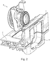
- Fig. 2 shows a perspective detailed view of the outlet recess 6, which is arranged in the illustrated preferred embodiment in the container bottom 2 or in a bottom edge 3 formed by this.
- an exemplary valve arrangement 8 is also shown, which can be inserted into the outlet recess 6 from the inside of the container.
- the outlet recess 6 can be closed on the outside of the container with a cover 10.
- the one shown here Cover 10 is designed like a flap.
- the cover 10 has a base section 12, which is arranged in the direction of the top of the container in the example shown and with which the cover is fixed to the container 1 or to the bottom 2, as well as a closure section 16, which represents the structure closing the outlet recess 6.
- the closure section 16 is pivotably connected to the base section 12 via a hinge arrangement 14.
- the cover 10 fits into the outer surface of the base edge 3 in an essentially planar manner.
- an area of the outer surface of the bottom edge 3 immediately adjacent to the outlet recess 6 is indented opposite the remaining lateral outer surface, so that the cover 10 can be inserted into this indentation.
- a handle recess 5 is provided on the lower edge of the base 2, adjacent to the indentation into which the cover 10 is inserted.
- FIG. 4 Figure 10 shows cover 10 of FIG Fig. 3 in an open state.
- the closure section 16 is pivoted about a pivot axis A defined by the hinge arrangement 14.
- the illustrated cover 10 or its hinge arrangement 14 is designed according to the invention to be self-supporting, ie it locks itself automatically in a defined open position, as will be explained in more detail below.
- the defined open position in which the closure section 16 is locked is selected so that the opening is completely released, but the flap is not pivoted completely through 180 °, but an opening angle between 10 ° and 30 ° relative to the side surface of the container 1 remains. This has the advantage that the closure section 16 can be more easily grasped from behind for closing, since it does not rest against the side surface of the container 1.
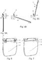
- the Figures 5A to 5C show a side view of the cover 10 with a self-supporting closure body 16 according to a first embodiment.
- the hinge arrangement 14 is designed as a so-called bistable hinge or snap hinge.
- the hinge assembly 14 has a film hinge 15 which defines the fundamental pivot axis A of the closure section 16.
- the hinge arrangement 14 in this example has two prestressing or spring elements 18, which act here as tension spring elements, in order to bring about a snap action of the hinge 14.
- the spring element 18 is in a relaxed state in the closed state of the cover 10, in which the base section 12 and the closure section 16 are arranged essentially in alignment.
- the illustrated position of the closure section 16 forms a first rest position of the bistable hinge arrangement 14.
- two end points 19 thereof are at a distance r from one another.
- a first end point 19 of the spring element 18 is pivotably connected to the base section 12 via a film hinge and a second end point 19 of the spring element 18 is also pivotably connected to the closure section 16 via a film hinge. Since the spring element 18 is pivotably connected both to the base section 12 and to the closure section 16, it can track the pivoting movement of the closure section 16.
- Figure 5C shows this second rest position of the bistable hinge arrangement 14, which represents a defined open state of the cover 10.
- the distance between the two end points 19 of the spring element 18 in this second rest position again corresponds to the distance r, as in the first rest position.
- the hinge arrangement 14 according to the first exemplary embodiment causes the closure section 16 to automatically snap upwards after a predetermined deflection or when a predetermined pressure point is exceeded and is held or locked in this open position in a self-supporting manner by the spring force of the prestressing element 18.
- the bistable hinge is pretensioned in the closed position and can thus provide better tightness when closing.
- Fig. 6 shows the cover 10 with bistable hinge arrangement 14 according to a first exemplary embodiment in a cut-away illustration.
- Figure 7 shows a second, alternative embodiment for a cover 10 with a bistable hinge 15.
- the bistability or snap action of the film hinge 15 is generated in that a bend is introduced into the film hinge. Since the course of the film hinge 15 no longer coincides with the pivot axis A defined by it due to the introduction of the bend, the film hinge 15 functions per se in this embodiment as a resilient bending element that produces a snap action.
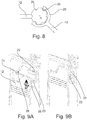
- Figure 8 shows a further alternative embodiment of the present invention in which the self-supporting cover is not realized by means of a bistable hinge but by means of complementary latching elements 28, 30 between the base section 12 and the closure section 16.
- the base section 12 has a type of toothing running in the circumferential direction of the hinge arrangement 14 coaxially to the pivot axis A, into which the locking projections 30 carried on resilient arms 29 engage.
- the geometry of the toothing 28 and the projections 30, together with the spring force of the arms 29, is set so that the hinge arrangement can easily be pivoted manually, but the holding force generated by the complementary latching elements 28, 30 is sufficient to keep the closure section 16 self-supporting .
- the cover 10 is equipped with a locking mechanism that can be detached and fastened without tools.
- the illustrated preferred embodiment of the cover 10 can be fastened to the container 1 in an uncomplicated manner via a snap mechanism. This is advantageous since the cover is a wear part of the container 1.
- Corresponding covers 10 are often damaged when handling containers 1 by means of floor conveyors such as forklifts, for example.
- a latching lug or a latching projection 20 is arranged above the outlet recess 6 on the outer surface of the indentation.
- This is adapted and provided to be brought into engagement with a corresponding latching recess 22 on the base section 12 of the cover 10.
- the latching recess 22 is located in an upper area of the base section 12 facing the inside of the container.
- a guide bevel 23 is formed, which enables it to slide over the also beveled latching lug 20, thus creating a snap action to create.
- a guide rib 24, which dips into a complementary groove or a guide slot 26 on the upper edge of the indentation above the outlet recess 6 in the container 1, ensures a guided assembly movement and a secure snap-in of the cover 10 during assembly on the container 1.
Landscapes
- Engineering & Computer Science (AREA)
- Mechanical Engineering (AREA)
- Closures For Containers (AREA)
Abstract
Description
- Die vorliegende Erfindung betrifft einen Behälter zum Transport und zur Lagerung flüssiger, viskoser oder rieselfähiger Stoffe, insbesondere der Intermediate Bulk Container Bauart, mit einem Boden, einer Seitenwandung und zumindest einer Auslassausnehmung im Boden und/oder der Seitenwandung, in welcher ein Auslassventil angeordnet oder anordenbar ist und welche mittels einer Abdeckung behälterseitig verschließbar ist.
- Sogenannte Großpackmittel bzw. Intermediate Bulk Container (IBC) werden zum Transport und zur Lagerung flüssiger und rieselfähiger Stoffe verwendet. Sie werden bspw. bei der Produktion von Chemikalien, Lebensmitteln, Kosmetik und Pharmazeutika eingesetzt. Solche Behälter weisen in der Regel ein Auslassventil in Bodennähe auf, welches in einer Auslassausnehmung bzw. einem VentilMontageschacht in der Außenwand des Behälters montiert ist und mittels welchem der fließ- oder rieselfähige Inhalt des Behälters entnommen werden kann.
- Es ist im Stand der Technik allgemein bekannt, bei solchen IBC eine Abdeckung in Form einer Klappe an der Außenseite der Auslassausnehmung (des Ventil-Montageschachts) vorzusehen. Mit einer solchen Abdeckung kann bis zu einem gewissen Grad eine Schutzwirkung bspw. gegen Staub bewerkstelligt werden. Die bekannten klappenartigen Abdeckungen können die Auslassausnehmung jedoch teilweise nicht vollständig abdecken, da sie nur lose vor dieser baumeln, was zu einer schlechten Staubdichtigkeit führt. Zudem muss der Anwender zum Erreichen der Auslassausnehmung bzw. des Auslassventils in derartigen bekannten Behältern die Abdeckung oftmals manuell in einer geöffneten Stellung halten, sodass nur eine Hand zum Bedienen, zur Montage des Ventils oder zum Anschließen eines Schlauchs an dieses verbleibt.
- Ein weiteres Problem, das im Zusammenhang mit den vorstehend beschriebenen Abdeckungen häufig auftritt, ist deren Beschädigung bei der Handhabung der Behälter mit Flurfördermitteln.
- Einige Behälter aus dem Stand der Technik weisen Vorrichtungen auf, mittels welchen die Abdeckung im geöffneten Zustand am Behälter verrastet werden kann. Solche Lösungen sind jedoch unpraktisch, wenn die Abdeckung beschädigt wird, da dann oftmals sowohl die Arretierungsvorrichtung am Behälter als auch die Abdeckung ausgetauscht werden muss.
- Es existieren weitere Lösungen im Stand der Technik, bei denen die Abdeckung zum Erreichen des Auslassventils vollständig vom Behälter entfernt wird. Bei derartigen Behältern muss der Anwender nach der Installation des Ventils oder dem Durchführen eines Entleerungsvorgangs die Abdeckung auch manuell wieder auf die Auslassausnehmung aufsetzen, was die Anzahl benötigter Arbeitsschritte erhöht. Zudem muss die Abdeckung bei solchen Behältern im demontierten Zustand verstaut werden, damit sie nicht verloren geht.
- Es besteht also ein Bedarf nach einem Behälter zum Transport und zur Lagerung flüssiger, viskoser oder rieselfähiger Stoffe, insbesondere der Intermediate Bulk Container Bauart, der eine Abdeckung für eine Auslassausnehmung des Behälters mit verbesserter Handhabbarkeit bereitstellt, die vorteilhafter Weise zudem bei einem Defekt leicht austauschbar ist.
- Die vorstehend beschriebenen Aufgaben werden durch einen Behälter gemäß dem unabhängigen Patentanspruch 1 gelöst. Vorteilhafte Weiterbildungen der Erfindung sind Gegenstand der Unteransprüche.
- Grundsätzlich hat ein erfindungsgemäßer Behälter zum Transport und zur Lagerung flüssiger, viskoser oder rieselfähiger Stoffe einen Boden, eine Seitenwandung und zumindest eine Auslassausnehmung im Boden und/oder der Seitenwandung, in welcher ein Auslassventil angeordnet oder anordenbar ist. Die Auslassausnehmung ist mittels einer Abdeckung behälteraußenseitig verschließbar. Die Auslassausnehmung hat einen Basisabschnitt und einen Verschlussabschnitt. Der Basisabschnitt ist dazu ausgebildet, am Behälter befestigt oder befestigbar zu sein. Der Verschlussabschnitt ist dazu ausgebildet, die Auslassausnehmung verschließen zu können.
- Der Verschlussabschnitt ist über eine Scharnieranordnung um eine Drehachse schwenkbar am Basisabschnitt angelenkt, sodass der Verschlussabschnitt von einer ersten, die Auslassausnehmung verschließenden Stellung, in eine zweite, die Auslassausnehmung freigebende Stellung überführbar ist. Die Scharnieranordnung ist dazu ausgebildet ist, den Verschlussabschnitt in der zweiten, die Auslassausnehmung freigebenden Stellung selbsttragend zu halten oder zu arretieren. In anderen Worten ist eine schwenkbare Abdeckung/Klappe für eine Auslassausnehmung eines Behälters so ausgebildet, dass ihre Scharnieranordnung den Verschlussabschnitt bzw. die Klappe der Abdeckung in der geöffneten Stellung arretiert/sichert. Wenn die Abdeckung nach oben (entgegen der Schwerkraft) geöffnet wird, ist die Haltekraft der Arretierung zudem zumindest so stark ausgelegt, dass sie den Verschlussabschnitt entgegen der Schwerkraft selbsttragend halten kann.
- Der erfindungsgemäße Behälter hat den Vorteil, dass die Abdeckung zuverlässig in einer geöffneten Position gehalten werden kann, wenn die Auslassausnehmung oder das Auslassventil erreicht werden müssen. Dadurch hat der Anwender beide Hände für Montage- oder Bedientätigkeiten am Ventil frei und es wird zudem ein versehentliches Verschließen der Abdeckung während eines Montagevorgangs vermieden. Die Arretierung in der geöffneten Stellung wird gemäß der Erfindung durch die Scharnieranordnung der Abdeckung per se bewerkstelligt. Dies hat den Vorteil, dass der gesamte Arretierungsmechanismus Teil der Abdeckung ist und bei einem Defekt in einfacher Weise gemeinsam mit der Abdeckung ausgetauscht werden kann.
- Bevorzugt kann es sich bei dem Behälter um einen Großladungsträger der Intermediate Bulk Container Bauart handeln, der einen internen Tank mit einem Auslassventil aufweist, welcher in einer äußeren Tragstruktur aus Boden und Seitenwandung beherbergt wird.
- Gemäß einer bevorzugten Ausführungsform kann die Scharnieranordnung ein Vorspann- oder Federelement aufweisen, das dazu ausgebildet ist, den Verschlussköper in der zweiten, geöffneten Stellung zu halten. Eine solche Ausgestaltung der Erfindung hat den Vorteil, dass unter der Vorspannungsbeaufschlagung die Abdeckung automatisch in eine definierte, geöffnete Position überführt werden kann, d.h. selbst wenn ein Anwender die Abdeckung manuell nicht vollständig öffnet, schnappt die Abdeckung von selbst in eine vollständig geöffnete Stellung.
- Gemäß einem bevorzugten Aspekt der Erfindung kann die Scharnieranordnung als bistabiles Scharnier ausgebildet sein, das je nach seiner relativen Lage bezüglich eines Druckpunktes entweder in die erste, die Auslassausnehmung verschließende Stellung, oder in die zweite, die Auslassausnehmung freigebende, Stellung vorgespannt ist. In anderen Worten kann das Scharnier der Abdeckung als sogenanntes Schnappscharnier ausgestaltet sein, dass es entweder in eine definierte verschlossene oder eine definierte geöffnete Stellung geschnappt ist, je nach relativer Lage des Verschlussabschnittes relativ zu einem Druckpunkt. Eine solche Ausführungsform hat den Vorteil, dass sich die Abdeckung immer entweder in einer komplett geschlossenen oder in einer definiert geöffneten Stellung befindet, wodurch Bedienfehler, wie bspw. ein unvollständiges Verschließen der Abdeckung vermieden werden.
- Gemäß einem bevorzugten Aspekt der Erfindung kann die Abdeckung stoffeinstückig als Kunststoffbauteil, insbesondere aus einem thermoplastischen Werkstoff, gefertigt sein. Dies ermöglicht es, die Abdeckung als einfach zu fertigendes und günstig herzustellendes Austauschteil auszulegen. Gemäß einer weiter bevorzugten Ausführungsform kann das bistabile Scharnier als eine Filmscharnieranordnung ausgebildet sein. Die Umsetzung des Scharniers als Filmscharnier unterstützt die Auslegung der Abdeckung als einfaches, einstückig zu fertigendes Austauschteil. Bevorzugt kann die Abdeckung in einem Stück als Spritzgussteil gefertigt sein.
- Gemäß einem bevorzugten Aspekt der Erfindung kann das bistabile Scharnier als ein gekrümmtes Filmscharnier ausgeführt sein. Durch einbringen einer Krümmung bzw. Wölbung in das Filmscharnier kann auf einfache Weise Spannung in das Scharnier gebracht und eine Schnappwirkung erzeugt werden. Das Filmscharnier bildet in einem solchen Fall per se das Vorspann- oder Federelement aus, das den Verschlusskörper in der zweiten, geöffneten Stellung vorspannt/hält.
- Gemäß einer bevorzugten Ausführungsform kann das bistabile Scharnier als Vorspann- oder Federelement ein federndes, eine Schnappwirkung erzeugendes Biegeelement oder Zugelement aufweisen.
- Gemäß einem bevorzugten Aspekt der Erfindung kann die Scharnieranordnung komplementäre Rast- oder Reibelemente an den angrenzenden Enden des Basisabschnitts und des Verschlussabschnitts aufweisen, die dazu ausgebildet sind, den Verschlussabschnitt selbsttragend in der zweiten Stellung zu halten. Als Alternative zu einer Ausführungsform mit Vorspannelementen kann die Scharnieranordnung demnach auch durch eine in verschiedenen Schwenkpositionen einrastende Verzahnung oder einen Reibschluss selbstragend ausgelegt sein.
- Gemäß einer bevorzugten Ausführungsform kann der Verschlussabschnitt in der zweiten, die Auslassausnehmung freigebenden, Stellung um einen Winkel von 135° bis 190°, bevorzugt zwischen 150° und 170°, gegenüber der ersten Stellung um die Schwenkachse (A) rotiert sein. Bevorzugt kann der Verschlussabschnitt in der ersten, die Auslassausnehmung verschließenden Stellung im Wesentlichen vertikal ausgerichtet sein. In handelsüblichen Behältern ist der Verschlussabschnitt in der ersten, die Auslassausnehmung verschließenden Stellung zumeist vertikal bzw. parallel zur Behälterseitenfläche ausgerichtet. Es ist von Vorteil, wenn die Abdeckung um etwas weniger als 180° aus dieser die Auslassausnehmung verschließenden Stellung in die definierte geöffnete Stellung rotiert wird, sodass zum einen die Auslassausnehmung zuverlässig freigegeben wird, zum anderen aber ein Hintergreifen der geöffneten Abdeckung noch einfach möglich ist (diese nicht an der Seitenwand anliegt).
- Gemäß einer bevorzugten Ausführungsform kann der Basisabschnitt werkzeuglos lösbar und befestigbar am Behälter angebracht sein. Dies ermöglicht einen schnellen Austausch einer beschädigten Abdeckung. Da die komplette Vorrichtung zum Arretieren der Abdeckung in der geöffneten Stellung Teil der Abdeckung selbst ist, kann auch diese auf einfache Weise durch Austausch der Abdeckung erneuert werden.
- Gemäß einem bevorzugten Aspekt der Erfindung kann der Basisabschnitt eine, insbesondere an einer von der Scharnieranordnung abgewandten Seite des Basisabschnitts angeordnete, Rastausnehmung aufweisen, der dazu ausgebildet und vorgesehen ist, mit einem korrespondierenden Rastvorsprung am Behälter nahe der Auslassausnehmung in Eingriff gebracht zu werden. Eine umgekehrte Anordnung von Rastvorsprung und Rastausnehmung ist ebensogut möglich. In anderen Worten kann eine Schnappverbindung zum einfachen, werkzeuglosen Festclipsen der Abdeckung am Behälter vorgesehen sein.
- Gemäß einer bevorzugten Ausführungsform kann der Basisabschnitt eine Führungsrippe aufweisen und der Behälter kann im Bereich der Auslassausnehmung einen korrespondierenden Führungsschlitz aufweisen. Auf diese Weise kann die Montage der Abdeckung am Behälter weiter vereinfacht werden.
- Gemäß einer bevorzugten Ausführungsform können sowohl der Basisabschnitt als auch der Verschlussabschnitt eine im Wesentlichen plattenförmige Struktur aufweisen und an angrenzenden Seitenkante durch die Scharnieranordnung miteinander verbunden sein. Eine solche Formgebung ermöglicht eine einfache Werkzeuggestaltung für die Fertigung der Abdeckung.
- Gemäß einem bevorzugten Aspekt der Erfindung kann der Verschlusskörper in der ersten, die Auslassausnehmung verschließenden Stellung sich bündig in die Außenfläche des Bodens und/oder der Seitenwandung einfügen. Eine solche Auslegung des Behälters und der Abdeckung vermeidet eine Beschädigung der letzteren, da keine Kante der Abdeckung im verschlossenen Zustand aus der Behälterseitenfläche herausragt, an der man hängenbleiben könnte. Zu diesem Zweck kann bevorzugt ein Bereich der Außenfläche des Behälters angrenzend zur Auslassausnehmung eingerückt sein, sodass die, insbesondere plattenförmige, Abdeckung in die Einrückung eingesetzt/eingefügt werden kann.
- Die vorliegende Erfindung wird nachfolgend anhand beispielhafter Ausführungsbeispiele erläutert, die zur besseren Veranschaulichung in den Figuren dargestellt sind.
-
Fig. 1 ist eine Darstellung eines Intermediate Bulk Containers gemäß einer bevorzugten Ausführungsform; -
Fig. 2 ist eine Darstellung zur Veranschaulichung einer Auslassausnehmung eines Behälters gemäß einer bevorzugten Ausführungsform sowie zur Veranschaulichung eines Einsetzvorgangs für ein Auslassventil; -
Fig. 3 ist eine Darstellung einer Abdeckung für eine Auslassausnehmung gemäß einem ersten bevorzugten Ausführungsbeispiel in einem verschlossenen Zustand; -
Fig. 4 ist eine Darstellung der Abdeckung für eine Auslassausnehmung in einem geöffneten Zustand; -
Fign. 5A bis 5C zeigen einen Öffnungsvorgang der Abdeckung für eine Auslassausnehmung gemäß dem ersten Ausführungsbeispiel; -
Fig. 6 zeigt die Abdeckung gemäß dem ersten Ausführungsbeispiel in einer freigeschnittenen Darstellung; -
Fig. 7 zeigt eine Abdeckung gemäß einem zweiten Ausführungsbeispiel in einer freigeschnittenen Darstellung; -
Fig. 8 zeigt einen Rastmechanismus für eine selbsttragende Abdeckung gemäß einem dritten Ausführungsbeispiel; und -
Fign. 9A und 9B zeigen eine Detailansicht des Rastmechanismus zum Befestigen der Abdeckung am Behälter. -
Fig. 1 zeigt eine perspektivische Darstellung eines Behälters 1 gemäß einem bevorzugten Ausführungsbeispiel der vorliegenden Erfindung. Bei dem dargestellten Behälter 1 handelt es sich um einen sogenannten Intermediate Bulk Container. Behälter dieser Bauart weisen einen Boden 2, der zumeist eine palettenartige Unterbodenstruktur aufweist, sowie eine sich Boden aus aufwärts erstreckende Seitenwandung 4 auf. Der dargestellte Behälter 1 hat zudem einen Deckel, der hier nicht näher bezeichnet ist. Die vorstehend beschriebenen Elemente bilden eine Außenstruktur des Behälters 1, die einen innenliegenden Tank oder Beutel (nicht dargestellt) vor äußeren Einwirkungen abschirmen und zudem eine Stapelbarkeit baugleicher Behälter 1 bereitstellen. Solche Intermediate Bulk Container ermöglichen einen sicheren Transport flüssiger, viskoser oder rieselfähiger Güter. Um besagte Güter aus dem Behälter 1 entnehmen zu können, ist der innenliegende Tank oder Beutel an seiner Unterseite bzw. in einem unteren Bereich mit einem Auslassventil 8 ausgestattet, das in derFig. 1 nicht näher dargestellt ist. Um dieses Auslassventil 8 von außerhalb des Behälters 1 her zugänglich zu machen, weist der Behälter 1 in seiner Außenstruktur, d. h. in seinem Boden 2 und oder seiner Seitenwandung 4, eine Auslassausnehmung 6 auf, die einen Durchbruch durch besagte Außenstruktur bzw. einen Montageschacht für das Ventil 8 darstellt. Zum Schutz vor Staub und anderen äußeren Einwirkungen ist besagte Auslassausnehmung 6 behälteraußenseitig durch eine Abdeckung 10 geschützt. -
Fig. 2 zeigt eine perspektivische Detailansicht der Auslassausnehmung 6, die im dargestellten bevorzugten Ausführungsbeispiel im Behälterboden 2 bzw. in einem von diesem ausgebildeten Bodenrand 3 angeordnet ist. InFig. 2 ist zudem eine beispielhafte Ventilanordnung 8 dargestellt, die von der Behälterinnenseite her in die Auslassausnehmung 6 einsetzbar ist. - Wie in der
Fig. 3 dargestellt ist, kann die Auslassausnehmung 6 behälteraußenseitig mit einer Abdeckung 10 verschlossen werden. Die hier dargestellte Abdeckung 10 ist klappenartig ausgebildet. In ihrem Grundaufbau hat die Abdeckung 10 einen im gezeigten Beispiel in Richtung hin zur Behälteroberseite angeordneten Basisabschnitt 12, mit welchem die Abdeckung am Behälter 1 bzw. am Boden 2 fixiert ist, sowie einen Verschlussabschnitt 16, welcher die die Auslassausnehmung 6 verschließende Struktur darstellt. Der Verschlussabschnitt 16 ist über eine Scharnieranordnung 14 mit dem Basisabschnitt 12 schwenkbar verbunden. - Wie ebenfalls in der
Fig. 3 gut zu erkennen ist, fügt sich die Abdeckung 10 im Wesentlichen plan in die Außenfläche des Bodenrandes 3 ein. Hierzu ist ein unmittelbar zur Auslassausnehmung 6 benachbarter Bereich der Außenfläche des Bodenrandes 3 gegenüber der restlichen seitlichen Außenfläche eingerückt, sodass die Abdeckung 10 in diese Einrückung eingesetzt werden kann. Um trotzdem eine gute Zugänglichkeit zur Abdeckung 10 zu gewährleisten und diese öffnen zu können ist an der Unterkante des Bodens 2 benachbarte zur Einrückung, in welche die Abdeckung 10 eingesetzt ist, eine Griffausnehmung 5 vorgesehen. -
Fig. 4 zeigt die Abdeckung 10 derFig. 3 in einem geöffneten Zustand. Zum Öffnen wird der Verschlussabschnitt 16 um eine durch die Scharnieranordnung 14 definierte Schwenkachse A geschwenkt. Die dargestellte Abdeckung 10 bzw. deren Scharnieranordnung 14 ist erfindungsgemäß selbsttragend ausgeführt, d.h. sie arretiert sich selbstständig in einer definierten geöffneten Position, wie im Folgenden genauer erläutert wird. Wie inFig. 4 gut zu erkennen ist, ist die definierte geöffnete Position, in welche der Verschlussabschnitt 16 arretiert wird, so gewählt, dass die Öffnung komplett freigegeben wird, die Klappe jedoch nicht komplett um 180° geschwenkt wird, sondern ein Öffnungswinkel zwischen 10° und 30° relativ zur Seitenfläche des Behälters 1 verbleibt. Dies hat den Vorteil, dass der Verschlussabschnitt 16 zum Verschließen leichter hintergriffen werden kann, da er nicht an der Seitenfläche des Behälters 1 anliegt. - Die
Figuren 5A bis 5C zeigen eine Seitenansicht der Abdeckung 10 mit selbsttragendem Verschlusskörper 16 gemäß einem ersten Ausführungsbeispiel. Im ersten Ausführungsbeispiel ist die Scharnieranordnung 14 als ein sogenanntes bistabiles Scharnier oder Schnappscharnier ausgebildet. Die Scharnieranordnung 14 weist ein Filmscharnier 15 auf, welches die grundsätzliche Schwenkachse A des Verschlussabschnitts 16 definiert. Zusätzlich weist die Scharnieranordnung 14 in diesem Beispiel zwei Vorspann- bzw. Federelemente 18, die hier als Zugfederelemente wirken, auf, um eine Schnappwirkung des Scharniers 14 zu bewerkstelligen. - Wie in der
Fig. 5A zu erkennen ist, befindet sich das Federelement 18 im verschlossenen Zustand der Abdeckung 10, in welchem der Basisabschnitt 12 und der Verschlussabschnitt 16 im Wesentlichen fluchtend angeordnet sind, in einem entspannten Zustand. Die inFigur 5A dargestellte Position des Verschlussabschnitts 16 bildet eine erste Ruheposition der bistabilen Scharnieranordnung 14. Im entspannten Zustand des Federelements 18 haben zwei Endpunkte 19 desselben einen Abstand r voneinander. Ein erster Endpunkt 19 des Federelements 18 ist über einen Filmscharnier schwenkbar dem Basisabschnitt 12 und ein zweiter Endpunkt 19 des Federelements 18 ist ebenfalls über ein Filmscharnier schwenkbar mit dem Verschlussabschnitt 16 verbunden. Da das Federelement 18 sowohl mit dem Basisabschnitt 12 als auch mit dem Verschlussabschnitt 16 schwenkbar verbunden ist, kann dieses die Schwenkbewegung des Verschlussabschnitts 16 nachverfolgen. Da aber die Endpunkte 19 (Filmscharniere) des Federelements gegenüber dem Filmscharnier 15 zwischen Basisabschnitt 12 und Verschlussabschnitt 16 einen Versatz aufweisen, führen die Federelemente 18 keine konzentrische Drehung mit dem Verschlussabschnitt 16 durch. Dies hat zur Folge, dass, wenn der Verschlussabschnitt 16 aus der inFig. 5A dargestellten Position heraus geschwenkt wird, sich das Federelements 18 längen muss. - In
Fig. 5B ist gut zu sehen, wie der Abstand der beiden Endpunkte 19 des Federelements 18 in einer verschwenkten Position den Abstand r aus dem entspannten Zustand des Federelements 18 deutlich überschreitet. In anderen Worten wird das Federelement 18 gestreckt, sobald es die Scharnieranordnung 14 die Ruheposition verlässt. Bei kleinen Auslenkungen aus dem inFig. 5A dargestellten verschlossenen Zustand schnappt der Verschluss Abschnitt deshalb unter der Vorspannung der Federelemente der 18 wieder in seine Ausgangsposition zurück. Der inFig. 5B dargestellte Zustand stellt einen Druckpunkt dar, in welchem bei einem Schwenken des Verschlussabschnitt 16 um das Filmscharnier 15 das Federelement 18 maximal gestreckt ist. Bei einem weiteren Schwenken des Verschlussabschnitts 16 in Richtung gegen den Uhrzeigersinn (in der gewählten Darstellung) verkürzt sich der Abstand der beiden Endpunkte 19 des Federelements 18 wieder. Die Vorspannkraft des Federelements 18 wirkt also ab Überschreiten des Druckpunktes in Richtung hin zu einem zweiten entspannten Zustand des Federelements 18 bzw. einer zweiten Ruheposition der Scharnieranordnung 14. -
Fig. 5C zeigt diese zweite Ruheposition der bistabilen Scharnieranordnung 14, die einen definierten geöffneten Zustand der Abdeckung 10 darstellt. Wie ebenfalls in derFig. 5C gut zu erkennen ist, entspricht der Abstand der beiden Endpunkte 19 des Federelements 18 in dieser zweiten Ruheposition wieder dem Abstand r, wie schon in der ersten Ruheposition. Zusammengefasst bewirkt die Scharnieranordnung 14 gemäß dem ersten Ausführungsbeispiel, dass der Verschlussabschnitt 16 ab einer vorbestimmten Auslenkung bzw. ab dem Überschreiten eines vorbestimmten Druckpunktes selbstständig nach oben schnappt und durch die Federkraft des Vorspannelements 18 selbsttragend in dieser geöffneten Position gehalten bzw. arretiert wird. Zudem wird das bistabile Scharnier in verschlossene Position vorgespannt und kann somit eine bessere Dichtigkeit beim Verschließen bereitstellen. -
Fig. 6 zeigt die Abdeckung 10 mit bistabiler Scharnieranordnung 14 gemäß einem ersten Ausführungsbeispiel in einer freigeschnittenen Darstellung.Figur 7 zeigt eine zweite, alternative Ausführungsform für eine Abdeckung 10 mit bistabilem Scharnier 15. In der Ausführungsform derFigur 7 wird die Bistabilität bzw. Schnappwirkung des Filmscharniers 15 dadurch erzeugt, dass eine Biegung in das Filmscharnier eingebracht ist. Da der Verlauf des Filmscharniers 15 durch das Einbringen der Biegung nicht mehr mit der von diesem definierten Schwenkachse A übereinstimmt, fungiert das Filmscharnier 15 in dieser Ausführungsform per se als federndes Biegeelement, das eine Schnappwirkung erzeugt. -
Figur 8 zeigt eine weitere alternative Ausführungsform der vorliegenden Erfindung, in der die selbsttragende Abdeckung nicht mittels einem bistabilen Scharnier sondern mittels komplementärer Rastelemente 28, 30 zwischen Basisabschnitt 12 und Verschlussabschnitt 16 realisiert ist. Wie inFigur 8 zu sehen ist, weist der Basisabschnitt 12 im dargestellten Beispiel koaxial zur Schwenkachse A eine Art in Umfangsrichtung der Scharnieranordnung 14 verlaufende Verzahnung auf, in die an federnden Armen 29 getragene Arretierungsvorsprünge 30 einrasten. Die Geometrie der Verzahnung 28 und der Vorsprünge 30 ist zusammen mit der Federkraft der Arme 29 so eingestellt, dass ein manuelles Verschwenken der Scharnieranordnung leicht möglich ist, die durch die komplementären Rastelemente 28, 30 erzeugte Haltekraft jedoch ausreicht, um den Verschlussabschnitt 16 selbsttragend zu halten. - Die Abdeckung 10 gemäß der bevorzugten Ausführungsform ist mit einem werkzeuglos lös- und befestigbaren Rastmechanismus ausgestattet. Insbesondere kann die dargestellte bevorzugte Ausführungsform der Abdeckung 10 über einen Schnappmechanismus unkompliziert am Behälter 1 befestigt werden. Dies ist von Vorteil, da die Abdeckung ein Verschleißteil des Behälters 1 ist. Entsprechende Abdeckungen 10 werden oftmals bei der Handhabung von Behältern 1 mittels Flurfördermitteln wie zum Beispiel Gabelstaplern beschädigt.
- In der dargestellten Ausführungsform ist, wie am besten in den
Figuren 9A und 9B zu sehen ist, oberhalb der Auslassausnehmung 6 an der Außenfläche der Einrückung eine Rastnase bzw. ein Rastvorsprung 20 angeordnet. Dieser ist dazu angepasst und vorgesehen mit einer entsprechenden Rastausnehmung 22 am Basisabschnitt 12 der Abdeckung 10 in Eingriff gebracht zu werden. Die Rastausnehmung 22 befindet sich in einem oberen zum Behälterinneren hin gewandten Bereich des Basisabschnitts 12. Zwischen der Oberkante des Basisabschnitts 12 und einer Oberkante der Rastausnehmung 22 ist eine Führungsschräge 23 ausgebildet, die ein Abgleiten über die ebenfalls angefaste Rastnase 20 ermöglicht, um so eine Schnappwirkung zu erzeugen. Eine Führungsrippe 24, die in eine komplementäre Nut bzw. einen Führungsschlitz 26 am oberen Rand der Einrückung oberhalb der Auslassausnehmung 6 im Behälter 1 eintaucht, sorgt für eine geführte Montagebewegung und ein sicheres Einschnappen der Abdeckung 10 bei der Montage am Behälter 1. -
- 1
- Behälter;
- 2
- Boden;
- 3
- Bodenrand;
- 4
- Seitenwandung;
- 5
- Griffausnehmung;
- 6
- Auslassausnehmung / Ventilmontageschacht;
- 8
- Auslassventil;
- 10
- Abdeckung;
- 12
- Basisabschnitt;
- 14
- Scharnieranordnung;
- 15
- Filmscharnier
- 16
- Verschlussabschnitt;
- 18
- Vorspannelement / Federelement;
- 20
- Rastvorsprung / Rastnase;
- 21
- Rücksprung;
- 22
- Rastausnehmung;
- 23
- Führungsschräge;
- 24
- Führungsrippe;
- 26
- Führungsschlitz;
- 28
- Verzahnung;
- 29
- Federarm;
- 30
- Arretierungsvorsprung und
- A
- Drehachse.
Claims (15)
- Behälter (1) zum Transport und zur Lagerung flüssiger, viskoser oder rieselfähiger Stoffe, insbesondere der Intermediate Bulk Container Bauart, mit einem Boden (2), einer Seitenwandung (4) und zumindest einer Auslassausnehmung (6) im Boden (2) und/oder der Seitenwandung (4), in welcher ein Auslassventil (8) angeordnet oder anordenbar ist und welche mittels einer Abdeckung (10) behälteraußenseitig verschließbar ist, wobei
die Abdeckung (10) einen Basisabschnitt (12), mittels welchem die Abdeckung (10) an dem Behälter (1) befestigt oder befestigbar ist, und einen Verschlussabschnitt (16), der über eine Scharnieranordnung (14) um eine Drechachse (A) schwenkbar am Basisabschnitt (12) angelenkt ist, aufweist, sodass
besagter Verschlussabschnitt (16) von einer ersten, die Auslassausnehmung (6) verschließenden Stellung, in eine zweite, die Auslassausnehmung (6) freigebende Stellung überführbar ist, dadurch gekennzeichnet, dass
die Scharnieranordnung (14) dazu ausgebildet ist, den Verschlussabschnitt (16) in der zweiten, die Auslassausnehmung (6) freigebenden Stellung selbsttragend zu halten oder zu arretieren. - Behälter (1) gemäß Anspruch 1, dadurch gekennzeichnet, dass die Scharnieranordnung (14) ein Vorspann- oder Federelement (18) aufweist, das dazu ausgebildet ist, den Verschlussköper (16) in der zweiten, geöffneten Stellung zu halten.
- Behälter (1) gemäß Anspruch 2, dadurch gekennzeichnet, dass die Scharnieranordnung (14) als bistabiles Scharnier ausgebildet ist, das je nach seiner relativen Lage bezüglich eines Druckpunktes entweder in die erste, die Auslassausnehmung (6) verschließende Stellung, oder in die zweite, die Auslassausnehmung (6) freigebende, Stellung vorgespannt ist.
- Behälter (1) gemäß Anspruch 3, dadurch gekennzeichnet, dass das bistabile Scharnier (14) eine Filmscharnieranordnung ist.
- Behälter (1) gemäß Anspruch 4, dadurch gekennzeichnet, dass das bistabile Scharnier (14) als ein gekrümmtes Filmscharnier ausgeführt ist.
- Behälter (1) gemäß Anspruch 4, dadurch gekennzeichnet, dass das bistabile Scharnier (14) als Vorspann- oder Federelement (18) ein federndes, eine Schnappwirkung erzeugendes Biegeelement oder Zugelement aufweist.
- Behälter (1) gemäß Anspruch 1, dadurch gekennzeichnet, dass die Scharnieranordnung (14) komplementäre Rastelemente (28, 30) an den angrenzenden Enden des Basisabschnitts (12) und des Verschlussabschnitts (16) aufweist, die dazu ausgebildet sind, den Verschlussabschnitt (16) selbsttragend in der zweiten Stellung zu halten.
- Behälter (1) gemäß einem der Ansprüche 1 bis 7, dadurch gekennzeichnet, dass der Verschlussabschnitt (16) in der zweiten, die Auslassausnehmung (6) freigebenden, Stellung um einen Winkel von 135° bis 190°, bevorzugt zwischen 150° und 170°, gegenüber der ersten Stellung um die Schwenkachse (A) rotiert ist.
- Behälter (1) gemäß Anspruch 8, dadurch gekennzeichnet, dass der Verschlussabschnitt in der ersten, die Auslassausnehmung (6) verschließenden Stellung im Wesentlichen vertikal ausgerichtet ist.
- Behälter (1) gemäß einem der Ansprüche 1 bis 9, dadurch gekennzeichnet, dass der Basisabschnitt (12) werkzeuglos lösbar und befestigbar am Behälter (1) angebracht ist.
- Behälter gemäß Anspruch 10, dadurch gekennzeichnet, dass der Basisabschnitt (12) mittels einer Schnappverbindung (20, 22) im Bereich der Auslassausnehmung (6) am Behälter (1) befestigbar ist.
- Behälter (1) gemäß einem der Ansprüche 1 bis 11, dadurch gekennzeichnet, dass der Basisabschnitt (12) eine Führungsrippe (24) aufweist und der Behälter (1) im Bereich der Auslassausnehmung (6) einen korrespondierenden Führungsschlitz (26) aufweist.
- Behälter (1) gemäß einem der Ansprüche 1 bis 12, dadurch gekennzeichnet, dass die Abdeckung (10) stoffeinstückig als Kunststoffbauteil gefertigt ist.
- Behälter (1) gemäß einem der Ansprüche 1 bis 13, dadurch gekennzeichnet, dass sowohl der Basisabschnitt (12) als auch der Verschlussabschnitt (16) eine im Wesentlichen plattenförmige Struktur aufweisen und an angrenzenden Seitenkante durch die Scharnieranordnung (14) miteinander verbunden sind.
- Behälter (1) gemäß einem der Ansprüche 1 bis 14, dadurch gekennzeichnet, dass der Verschlusskörper in der ersten, die Auslassausnehmung (6) verschließenden Stellung sich bündig in die Außenfläche des Bodens (2) und/oder (4) der Seitenwandung (4) einfügt.
Priority Applications (10)
| Application Number | Priority Date | Filing Date | Title |
|---|---|---|---|
| EP19172036.6A EP3733549B1 (de) | 2019-04-30 | 2019-04-30 | Behälter mit selbsttragender abdeckung für auslass |
| US17/606,422 US12017833B2 (en) | 2019-04-30 | 2020-03-25 | Container having a self-supporting cover for an outlet |
| US17/607,123 US11866241B2 (en) | 2019-04-30 | 2020-03-25 | Container having a self-supporting cover for an outlet |
| AU2020265713A AU2020265713B2 (en) | 2019-04-30 | 2020-03-25 | Container having a self-supporting cover for an outlet |
| CN202080032602.9A CN113767051B (zh) | 2019-04-30 | 2020-03-25 | 具有用于出口的自支撑盖的集装箱 |
| EP20712984.2A EP3962834A1 (de) | 2019-04-30 | 2020-03-25 | Behälter mit selbsttragender abdeckung für auslass |
| PCT/EP2020/058409 WO2020221519A1 (de) | 2019-04-30 | 2020-03-25 | Behälter mit selbsttragender abdeckung für auslass |
| CN202080032601.4A CN113874296B (zh) | 2019-04-30 | 2020-03-25 | 具有用于出口的自支撑盖的集装箱 |
| PCT/EP2020/058407 WO2020221518A1 (de) | 2019-04-30 | 2020-03-25 | Behälter mit selbsttragender abdeckung für auslass |
| ZA2021/09713A ZA202109713B (en) | 2019-04-30 | 2021-11-29 | Container having a self-supporting cover for an outlet |
Applications Claiming Priority (1)
| Application Number | Priority Date | Filing Date | Title |
|---|---|---|---|
| EP19172036.6A EP3733549B1 (de) | 2019-04-30 | 2019-04-30 | Behälter mit selbsttragender abdeckung für auslass |
Publications (2)
| Publication Number | Publication Date |
|---|---|
| EP3733549A1 true EP3733549A1 (de) | 2020-11-04 |
| EP3733549B1 EP3733549B1 (de) | 2022-04-06 |
Family
ID=66379713
Family Applications (2)
| Application Number | Title | Priority Date | Filing Date |
|---|---|---|---|
| EP19172036.6A Active EP3733549B1 (de) | 2019-04-30 | 2019-04-30 | Behälter mit selbsttragender abdeckung für auslass |
| EP20712984.2A Pending EP3962834A1 (de) | 2019-04-30 | 2020-03-25 | Behälter mit selbsttragender abdeckung für auslass |
Family Applications After (1)
| Application Number | Title | Priority Date | Filing Date |
|---|---|---|---|
| EP20712984.2A Pending EP3962834A1 (de) | 2019-04-30 | 2020-03-25 | Behälter mit selbsttragender abdeckung für auslass |
Country Status (6)
| Country | Link |
|---|---|
| US (2) | US12017833B2 (de) |
| EP (2) | EP3733549B1 (de) |
| CN (2) | CN113767051B (de) |
| AU (1) | AU2020265713B2 (de) |
| WO (2) | WO2020221519A1 (de) |
| ZA (1) | ZA202109713B (de) |
Families Citing this family (2)
| Publication number | Priority date | Publication date | Assignee | Title |
|---|---|---|---|---|
| US20240124223A1 (en) * | 2022-10-13 | 2024-04-18 | The Heil Co. | Bi-stable band actuator |
| KR20240134133A (ko) * | 2022-10-31 | 2024-09-06 | 로지팩, 아이앤씨 | 운송 박스(transport box) |
Citations (5)
| Publication number | Priority date | Publication date | Assignee | Title |
|---|---|---|---|---|
| US3629901A (en) * | 1968-04-30 | 1971-12-28 | Maria Hermine Wolf | Hinges |
| DE102007020886A1 (de) * | 2007-05-04 | 2008-11-06 | Protechna S.A. | Palettenbehälter zum Transport und zur Lagerung von flüssigen, pastösen, granulat- und pulverförmigen Füllgütern |
| CN201553333U (zh) * | 2009-06-26 | 2010-08-18 | 陕西秦川机械发展股份有限公司 | 更易成型的集装桶 |
| WO2011046628A1 (en) * | 2009-10-15 | 2011-04-21 | Smith Jack B | Adjustable door stop system |
| EP2894111A1 (de) * | 2012-09-04 | 2015-07-15 | Shanghai Hongyan Returnable Transit Packagings Co., Ltd. | Abdeckungsvorrichtung und behälter zum abdecken einer integrierten ventilmontagekanalöffnung eines grosssack-hebebandes |
Family Cites Families (17)
| Publication number | Priority date | Publication date | Assignee | Title |
|---|---|---|---|---|
| US5156268A (en) * | 1990-12-10 | 1992-10-20 | Hoover Group, Inc. | Composite shipping container for combustible liquids |
| US5316174A (en) * | 1991-03-15 | 1994-05-31 | Protechna Sa | Pallet container |
| US5924589A (en) * | 1997-07-21 | 1999-07-20 | Gordon; Gerald A. | Fire resistant composite intermediate bulk container |
| AUPO965097A0 (en) * | 1997-10-08 | 1997-10-30 | Technosearch Pty. Limited | Improvements in containers |
| FR2830000A1 (fr) * | 2001-09-26 | 2003-03-28 | Log6 | Conteneur |
| DE10161693A1 (de) * | 2001-12-15 | 2003-07-03 | Protechna Sa | Transport-und Lagerbehälter für Flüssigkeiten |
| US20050145521A1 (en) * | 2004-01-07 | 2005-07-07 | Perkins David W. | Bag nozzle retention system |
| DE102004039482B4 (de) * | 2004-08-14 | 2007-04-12 | Protechna S.A. | Flüssigkeitsbehälter aus Kunststoff |
| DE102006037944A1 (de) * | 2005-09-01 | 2007-03-15 | Protechna S.A. | Transport- und Lagerbehälter aus Kunststoff |
| DE102009005212A1 (de) * | 2009-01-20 | 2010-07-22 | Schoeller Arca Systems Gmbh | Behälter für Transport und Lagerung von Gütern mit einem Behälterboden und zumindest zwei übereinander klappbaren Seitenwänden |
| CA2944615C (en) * | 2014-02-28 | 2023-05-02 | Cdf Corporation | Semi-rigid shipping container with peel-reseal closure |
| US10308496B2 (en) | 2014-09-04 | 2019-06-04 | Vitop Mouldings S.R.L. | Liquid dispensing tap, particularly for dispensing liquids with higher densities from rigid vessels |
| US20160228831A1 (en) * | 2015-02-05 | 2016-08-11 | Claussen Technology, Llc | Liquid transfer system |
| EP3356244B1 (de) * | 2015-10-02 | 2020-08-19 | International Paper Company | Schüttgutbehälter ohne palette |
| US10994911B2 (en) | 2016-03-24 | 2021-05-04 | Mauser-Werke Gmbh | Pallet container including an inliner |
| ES2967122T3 (es) | 2018-01-18 | 2024-04-26 | Schoeller Allibert Gmbh | Contenedor con conjunto de válvula |
| US10961029B2 (en) | 2018-11-13 | 2021-03-30 | James Darwin Klosterbuer | Micro-spill prevention trough and method of use |
-
2019
- 2019-04-30 EP EP19172036.6A patent/EP3733549B1/de active Active
-
2020
- 2020-03-25 AU AU2020265713A patent/AU2020265713B2/en active Active
- 2020-03-25 CN CN202080032602.9A patent/CN113767051B/zh active Active
- 2020-03-25 US US17/606,422 patent/US12017833B2/en active Active
- 2020-03-25 WO PCT/EP2020/058409 patent/WO2020221519A1/de not_active Ceased
- 2020-03-25 WO PCT/EP2020/058407 patent/WO2020221518A1/de not_active Ceased
- 2020-03-25 US US17/607,123 patent/US11866241B2/en active Active
- 2020-03-25 CN CN202080032601.4A patent/CN113874296B/zh active Active
- 2020-03-25 EP EP20712984.2A patent/EP3962834A1/de active Pending
-
2021
- 2021-11-29 ZA ZA2021/09713A patent/ZA202109713B/en unknown
Patent Citations (5)
| Publication number | Priority date | Publication date | Assignee | Title |
|---|---|---|---|---|
| US3629901A (en) * | 1968-04-30 | 1971-12-28 | Maria Hermine Wolf | Hinges |
| DE102007020886A1 (de) * | 2007-05-04 | 2008-11-06 | Protechna S.A. | Palettenbehälter zum Transport und zur Lagerung von flüssigen, pastösen, granulat- und pulverförmigen Füllgütern |
| CN201553333U (zh) * | 2009-06-26 | 2010-08-18 | 陕西秦川机械发展股份有限公司 | 更易成型的集装桶 |
| WO2011046628A1 (en) * | 2009-10-15 | 2011-04-21 | Smith Jack B | Adjustable door stop system |
| EP2894111A1 (de) * | 2012-09-04 | 2015-07-15 | Shanghai Hongyan Returnable Transit Packagings Co., Ltd. | Abdeckungsvorrichtung und behälter zum abdecken einer integrierten ventilmontagekanalöffnung eines grosssack-hebebandes |
Also Published As
| Publication number | Publication date |
|---|---|
| EP3962834A1 (de) | 2022-03-09 |
| CN113874296B (zh) | 2023-04-25 |
| CN113767051A (zh) | 2021-12-07 |
| US20220212850A1 (en) | 2022-07-07 |
| WO2020221519A1 (de) | 2020-11-05 |
| AU2020265713B2 (en) | 2024-03-14 |
| US20220228410A1 (en) | 2022-07-21 |
| CN113767051B (zh) | 2023-09-19 |
| US11866241B2 (en) | 2024-01-09 |
| AU2020265713A1 (en) | 2021-12-23 |
| ZA202109713B (en) | 2023-04-26 |
| US12017833B2 (en) | 2024-06-25 |
| WO2020221518A1 (de) | 2020-11-05 |
| CN113874296A (zh) | 2021-12-31 |
| EP3733549B1 (de) | 2022-04-06 |
Similar Documents
| Publication | Publication Date | Title |
|---|---|---|
| AT401767B (de) | Müllbehälter | |
| EP2036838B1 (de) | Deckelanordnung für einen Flüssigkeitsbehälter | |
| DE69820898T2 (de) | Griff für geldkassette | |
| DE2943605A1 (de) | Abgabeverschluss | |
| CH683838A5 (de) | Behälter. | |
| DE2808832A1 (de) | Schliessvorrichtung fuer einen gepaeckkoffer | |
| DE2749946A1 (de) | Kniehebel-abgabeverschluss | |
| EP0685405A1 (de) | Behälterverschluss | |
| DE2548982B2 (de) | Tragbare Toilette | |
| DE69506495T2 (de) | Behälterverschluss | |
| EP3733549B1 (de) | Behälter mit selbsttragender abdeckung für auslass | |
| DE112006002236T5 (de) | Behälter mit offenem Ende und Verschlussdeckel | |
| DE202013002202U1 (de) | Behälterverschluss | |
| CH685550A5 (de) | Oeffnungsvorrichtung am Deckel einer Fliessmittelpackung. | |
| DE4334486A1 (de) | Kunststoffbehälter mit einrastbarem Deckel | |
| EP2128031B1 (de) | Vorrichtung zum Verbinden und Verschließen von Behältern | |
| EP0087088A2 (de) | Trageband für einen mit Deckel versehenen Behälter | |
| DE2725215A1 (de) | Verschluss | |
| CH695684A5 (de) | Behälter für Lebensmittel. | |
| EP2768752B1 (de) | Hülse für eine rohrpostanlage mit einem hülsenrohr | |
| DE9314627U1 (de) | Gehäuse für elektrische Geräte | |
| DE4128622C2 (de) | Verschluß | |
| EP0233972B1 (de) | Thermoplastspannring | |
| DE9418388U1 (de) | Sicherungsband für Handfeuerlöscher mit Zugschloß | |
| EP3655340A1 (de) | Behälter |
Legal Events
| Date | Code | Title | Description |
|---|---|---|---|
| PUAI | Public reference made under article 153(3) epc to a published international application that has entered the european phase |
Free format text: ORIGINAL CODE: 0009012 |
|
| STAA | Information on the status of an ep patent application or granted ep patent |
Free format text: STATUS: THE APPLICATION HAS BEEN PUBLISHED |
|
| AK | Designated contracting states |
Kind code of ref document: A1 Designated state(s): AL AT BE BG CH CY CZ DE DK EE ES FI FR GB GR HR HU IE IS IT LI LT LU LV MC MK MT NL NO PL PT RO RS SE SI SK SM TR |
|
| AX | Request for extension of the european patent |
Extension state: BA ME |
|
| STAA | Information on the status of an ep patent application or granted ep patent |
Free format text: STATUS: REQUEST FOR EXAMINATION WAS MADE |
|
| 17P | Request for examination filed |
Effective date: 20210429 |
|
| RBV | Designated contracting states (corrected) |
Designated state(s): AL AT BE BG CH CY CZ DE DK EE ES FI FR GB GR HR HU IE IS IT LI LT LU LV MC MK MT NL NO PL PT RO RS SE SI SK SM TR |
|
| GRAP | Despatch of communication of intention to grant a patent |
Free format text: ORIGINAL CODE: EPIDOSNIGR1 |
|
| STAA | Information on the status of an ep patent application or granted ep patent |
Free format text: STATUS: GRANT OF PATENT IS INTENDED |
|
| GRAJ | Information related to disapproval of communication of intention to grant by the applicant or resumption of examination proceedings by the epo deleted |
Free format text: ORIGINAL CODE: EPIDOSDIGR1 |
|
| GRAP | Despatch of communication of intention to grant a patent |
Free format text: ORIGINAL CODE: EPIDOSNIGR1 |
|
| RIC1 | Information provided on ipc code assigned before grant |
Ipc: E05D 11/10 20060101ALI20210921BHEP Ipc: B65D 77/06 20060101ALI20210921BHEP Ipc: B65D 77/04 20060101AFI20210921BHEP |
|
| INTG | Intention to grant announced |
Effective date: 20211013 |
|
| INTG | Intention to grant announced |
Effective date: 20211026 |
|
| GRAS | Grant fee paid |
Free format text: ORIGINAL CODE: EPIDOSNIGR3 |
|
| GRAA | (expected) grant |
Free format text: ORIGINAL CODE: 0009210 |
|
| STAA | Information on the status of an ep patent application or granted ep patent |
Free format text: STATUS: THE PATENT HAS BEEN GRANTED |
|
| AK | Designated contracting states |
Kind code of ref document: B1 Designated state(s): AL AT BE BG CH CY CZ DE DK EE ES FI FR GB GR HR HU IE IS IT LI LT LU LV MC MK MT NL NO PL PT RO RS SE SI SK SM TR |
|
| RAP3 | Party data changed (applicant data changed or rights of an application transferred) |
Owner name: SCHOELLER ALLIBERT GMBH |
|
| REG | Reference to a national code |
Ref country code: GB Ref legal event code: FG4D Free format text: NOT ENGLISH |
|
| REG | Reference to a national code |
Ref country code: CH Ref legal event code: EP |
|
| REG | Reference to a national code |
Ref country code: AT Ref legal event code: REF Ref document number: 1481158 Country of ref document: AT Kind code of ref document: T Effective date: 20220415 |
|
| REG | Reference to a national code |
Ref country code: IE Ref legal event code: FG4D Free format text: LANGUAGE OF EP DOCUMENT: GERMAN |
|
| REG | Reference to a national code |
Ref country code: DE Ref legal event code: R096 Ref document number: 502019003926 Country of ref document: DE |
|
| REG | Reference to a national code |
Ref country code: NL Ref legal event code: FP |
|
| REG | Reference to a national code |
Ref country code: LT Ref legal event code: MG9D |
|
| PG25 | Lapsed in a contracting state [announced via postgrant information from national office to epo] |
Ref country code: SE Free format text: LAPSE BECAUSE OF FAILURE TO SUBMIT A TRANSLATION OF THE DESCRIPTION OR TO PAY THE FEE WITHIN THE PRESCRIBED TIME-LIMIT Effective date: 20220406 Ref country code: PT Free format text: LAPSE BECAUSE OF FAILURE TO SUBMIT A TRANSLATION OF THE DESCRIPTION OR TO PAY THE FEE WITHIN THE PRESCRIBED TIME-LIMIT Effective date: 20220808 Ref country code: NO Free format text: LAPSE BECAUSE OF FAILURE TO SUBMIT A TRANSLATION OF THE DESCRIPTION OR TO PAY THE FEE WITHIN THE PRESCRIBED TIME-LIMIT Effective date: 20220706 Ref country code: LT Free format text: LAPSE BECAUSE OF FAILURE TO SUBMIT A TRANSLATION OF THE DESCRIPTION OR TO PAY THE FEE WITHIN THE PRESCRIBED TIME-LIMIT Effective date: 20220406 Ref country code: HR Free format text: LAPSE BECAUSE OF FAILURE TO SUBMIT A TRANSLATION OF THE DESCRIPTION OR TO PAY THE FEE WITHIN THE PRESCRIBED TIME-LIMIT Effective date: 20220406 Ref country code: GR Free format text: LAPSE BECAUSE OF FAILURE TO SUBMIT A TRANSLATION OF THE DESCRIPTION OR TO PAY THE FEE WITHIN THE PRESCRIBED TIME-LIMIT Effective date: 20220707 Ref country code: FI Free format text: LAPSE BECAUSE OF FAILURE TO SUBMIT A TRANSLATION OF THE DESCRIPTION OR TO PAY THE FEE WITHIN THE PRESCRIBED TIME-LIMIT Effective date: 20220406 Ref country code: ES Free format text: LAPSE BECAUSE OF FAILURE TO SUBMIT A TRANSLATION OF THE DESCRIPTION OR TO PAY THE FEE WITHIN THE PRESCRIBED TIME-LIMIT Effective date: 20220406 Ref country code: BG Free format text: LAPSE BECAUSE OF FAILURE TO SUBMIT A TRANSLATION OF THE DESCRIPTION OR TO PAY THE FEE WITHIN THE PRESCRIBED TIME-LIMIT Effective date: 20220706 |
|
| PG25 | Lapsed in a contracting state [announced via postgrant information from national office to epo] |
Ref country code: RS Free format text: LAPSE BECAUSE OF FAILURE TO SUBMIT A TRANSLATION OF THE DESCRIPTION OR TO PAY THE FEE WITHIN THE PRESCRIBED TIME-LIMIT Effective date: 20220406 Ref country code: PL Free format text: LAPSE BECAUSE OF FAILURE TO SUBMIT A TRANSLATION OF THE DESCRIPTION OR TO PAY THE FEE WITHIN THE PRESCRIBED TIME-LIMIT Effective date: 20220406 Ref country code: LV Free format text: LAPSE BECAUSE OF FAILURE TO SUBMIT A TRANSLATION OF THE DESCRIPTION OR TO PAY THE FEE WITHIN THE PRESCRIBED TIME-LIMIT Effective date: 20220406 Ref country code: IS Free format text: LAPSE BECAUSE OF FAILURE TO SUBMIT A TRANSLATION OF THE DESCRIPTION OR TO PAY THE FEE WITHIN THE PRESCRIBED TIME-LIMIT Effective date: 20220806 |
|
| REG | Reference to a national code |
Ref country code: CH Ref legal event code: PL |
|
| REG | Reference to a national code |
Ref country code: DE Ref legal event code: R097 Ref document number: 502019003926 Country of ref document: DE |
|
| PG25 | Lapsed in a contracting state [announced via postgrant information from national office to epo] |
Ref country code: SM Free format text: LAPSE BECAUSE OF FAILURE TO SUBMIT A TRANSLATION OF THE DESCRIPTION OR TO PAY THE FEE WITHIN THE PRESCRIBED TIME-LIMIT Effective date: 20220406 Ref country code: SK Free format text: LAPSE BECAUSE OF FAILURE TO SUBMIT A TRANSLATION OF THE DESCRIPTION OR TO PAY THE FEE WITHIN THE PRESCRIBED TIME-LIMIT Effective date: 20220406 Ref country code: RO Free format text: LAPSE BECAUSE OF FAILURE TO SUBMIT A TRANSLATION OF THE DESCRIPTION OR TO PAY THE FEE WITHIN THE PRESCRIBED TIME-LIMIT Effective date: 20220406 Ref country code: MC Free format text: LAPSE BECAUSE OF FAILURE TO SUBMIT A TRANSLATION OF THE DESCRIPTION OR TO PAY THE FEE WITHIN THE PRESCRIBED TIME-LIMIT Effective date: 20220406 Ref country code: LU Free format text: LAPSE BECAUSE OF NON-PAYMENT OF DUE FEES Effective date: 20220430 Ref country code: LI Free format text: LAPSE BECAUSE OF NON-PAYMENT OF DUE FEES Effective date: 20220430 Ref country code: EE Free format text: LAPSE BECAUSE OF FAILURE TO SUBMIT A TRANSLATION OF THE DESCRIPTION OR TO PAY THE FEE WITHIN THE PRESCRIBED TIME-LIMIT Effective date: 20220406 Ref country code: DK Free format text: LAPSE BECAUSE OF FAILURE TO SUBMIT A TRANSLATION OF THE DESCRIPTION OR TO PAY THE FEE WITHIN THE PRESCRIBED TIME-LIMIT Effective date: 20220406 Ref country code: CZ Free format text: LAPSE BECAUSE OF FAILURE TO SUBMIT A TRANSLATION OF THE DESCRIPTION OR TO PAY THE FEE WITHIN THE PRESCRIBED TIME-LIMIT Effective date: 20220406 Ref country code: CH Free format text: LAPSE BECAUSE OF NON-PAYMENT OF DUE FEES Effective date: 20220430 |
|
| PLBE | No opposition filed within time limit |
Free format text: ORIGINAL CODE: 0009261 |
|
| STAA | Information on the status of an ep patent application or granted ep patent |
Free format text: STATUS: NO OPPOSITION FILED WITHIN TIME LIMIT |
|
| 26N | No opposition filed |
Effective date: 20230110 |
|
| PG25 | Lapsed in a contracting state [announced via postgrant information from national office to epo] |
Ref country code: AL Free format text: LAPSE BECAUSE OF FAILURE TO SUBMIT A TRANSLATION OF THE DESCRIPTION OR TO PAY THE FEE WITHIN THE PRESCRIBED TIME-LIMIT Effective date: 20220406 |
|
| PG25 | Lapsed in a contracting state [announced via postgrant information from national office to epo] |
Ref country code: IE Free format text: LAPSE BECAUSE OF NON-PAYMENT OF DUE FEES Effective date: 20220430 |
|
| PG25 | Lapsed in a contracting state [announced via postgrant information from national office to epo] |
Ref country code: SI Free format text: LAPSE BECAUSE OF FAILURE TO SUBMIT A TRANSLATION OF THE DESCRIPTION OR TO PAY THE FEE WITHIN THE PRESCRIBED TIME-LIMIT Effective date: 20220406 |
|
| PG25 | Lapsed in a contracting state [announced via postgrant information from national office to epo] |
Ref country code: IT Free format text: LAPSE BECAUSE OF FAILURE TO SUBMIT A TRANSLATION OF THE DESCRIPTION OR TO PAY THE FEE WITHIN THE PRESCRIBED TIME-LIMIT Effective date: 20220406 |
|
| PG25 | Lapsed in a contracting state [announced via postgrant information from national office to epo] |
Ref country code: MK Free format text: LAPSE BECAUSE OF FAILURE TO SUBMIT A TRANSLATION OF THE DESCRIPTION OR TO PAY THE FEE WITHIN THE PRESCRIBED TIME-LIMIT Effective date: 20220406 Ref country code: CY Free format text: LAPSE BECAUSE OF FAILURE TO SUBMIT A TRANSLATION OF THE DESCRIPTION OR TO PAY THE FEE WITHIN THE PRESCRIBED TIME-LIMIT Effective date: 20220406 |
|
| PG25 | Lapsed in a contracting state [announced via postgrant information from national office to epo] |
Ref country code: HU Free format text: LAPSE BECAUSE OF FAILURE TO SUBMIT A TRANSLATION OF THE DESCRIPTION OR TO PAY THE FEE WITHIN THE PRESCRIBED TIME-LIMIT; INVALID AB INITIO Effective date: 20190430 |
|
| PG25 | Lapsed in a contracting state [announced via postgrant information from national office to epo] |
Ref country code: TR Free format text: LAPSE BECAUSE OF FAILURE TO SUBMIT A TRANSLATION OF THE DESCRIPTION OR TO PAY THE FEE WITHIN THE PRESCRIBED TIME-LIMIT Effective date: 20220406 |
|
| PG25 | Lapsed in a contracting state [announced via postgrant information from national office to epo] |
Ref country code: MT Free format text: LAPSE BECAUSE OF FAILURE TO SUBMIT A TRANSLATION OF THE DESCRIPTION OR TO PAY THE FEE WITHIN THE PRESCRIBED TIME-LIMIT Effective date: 20220406 |
|
| PG25 | Lapsed in a contracting state [announced via postgrant information from national office to epo] |
Ref country code: BG Free format text: LAPSE BECAUSE OF FAILURE TO SUBMIT A TRANSLATION OF THE DESCRIPTION OR TO PAY THE FEE WITHIN THE PRESCRIBED TIME-LIMIT Effective date: 20220406 |
|
| PG25 | Lapsed in a contracting state [announced via postgrant information from national office to epo] |
Ref country code: BG Free format text: LAPSE BECAUSE OF FAILURE TO SUBMIT A TRANSLATION OF THE DESCRIPTION OR TO PAY THE FEE WITHIN THE PRESCRIBED TIME-LIMIT Effective date: 20220406 |
|
| PGFP | Annual fee paid to national office [announced via postgrant information from national office to epo] |
Ref country code: NL Payment date: 20250422 Year of fee payment: 7 |
|
| REG | Reference to a national code |
Ref country code: AT Ref legal event code: MM01 Ref document number: 1481158 Country of ref document: AT Kind code of ref document: T Effective date: 20240430 |
|
| PGFP | Annual fee paid to national office [announced via postgrant information from national office to epo] |
Ref country code: GB Payment date: 20250423 Year of fee payment: 7 |
|
| PG25 | Lapsed in a contracting state [announced via postgrant information from national office to epo] |
Ref country code: AT Free format text: LAPSE BECAUSE OF NON-PAYMENT OF DUE FEES Effective date: 20240430 |
|
| PGFP | Annual fee paid to national office [announced via postgrant information from national office to epo] |
Ref country code: AT Payment date: 20260410 Year of fee payment: 5 |
|
| PGFP | Annual fee paid to national office [announced via postgrant information from national office to epo] |
Ref country code: DE Payment date: 20260408 Year of fee payment: 8 |
|
| PGFP | Annual fee paid to national office [announced via postgrant information from national office to epo] |
Ref country code: BE Payment date: 20260422 Year of fee payment: 8 |
|
| PGFP | Annual fee paid to national office [announced via postgrant information from national office to epo] |
Ref country code: FR Payment date: 20260422 Year of fee payment: 8 |