EP3733352A1 - Dispositif de protection pour un appareil-outil ainsi que système comprenant un dispositif de protection et un appareil-outil - Google Patents
Dispositif de protection pour un appareil-outil ainsi que système comprenant un dispositif de protection et un appareil-outil Download PDFInfo
- Publication number
- EP3733352A1 EP3733352A1 EP19171534.1A EP19171534A EP3733352A1 EP 3733352 A1 EP3733352 A1 EP 3733352A1 EP 19171534 A EP19171534 A EP 19171534A EP 3733352 A1 EP3733352 A1 EP 3733352A1
- Authority
- EP
- European Patent Office
- Prior art keywords
- tool device
- protective device
- tool
- protective
- handle
- Prior art date
- Legal status (The legal status is an assumption and is not a legal conclusion. Google has not performed a legal analysis and makes no representation as to the accuracy of the status listed.)
- Withdrawn
Links
Images


Classifications
-
- B—PERFORMING OPERATIONS; TRANSPORTING
- B25—HAND TOOLS; PORTABLE POWER-DRIVEN TOOLS; MANIPULATORS
- B25F—COMBINATION OR MULTI-PURPOSE TOOLS NOT OTHERWISE PROVIDED FOR; DETAILS OR COMPONENTS OF PORTABLE POWER-DRIVEN TOOLS NOT PARTICULARLY RELATED TO THE OPERATIONS PERFORMED AND NOT OTHERWISE PROVIDED FOR
- B25F5/00—Details or components of portable power-driven tools not particularly related to the operations performed and not otherwise provided for
- B25F5/02—Construction of casings, bodies or handles
-
- B—PERFORMING OPERATIONS; TRANSPORTING
- B24—GRINDING; POLISHING
- B24B—MACHINES, DEVICES, OR PROCESSES FOR GRINDING OR POLISHING; DRESSING OR CONDITIONING OF ABRADING SURFACES; FEEDING OF GRINDING, POLISHING, OR LAPPING AGENTS
- B24B23/00—Portable grinding machines, e.g. hand-guided; Accessories therefor
- B24B23/005—Auxiliary devices used in connection with portable grinding machines, e.g. holders
-
- B—PERFORMING OPERATIONS; TRANSPORTING
- B24—GRINDING; POLISHING
- B24B—MACHINES, DEVICES, OR PROCESSES FOR GRINDING OR POLISHING; DRESSING OR CONDITIONING OF ABRADING SURFACES; FEEDING OF GRINDING, POLISHING, OR LAPPING AGENTS
- B24B23/00—Portable grinding machines, e.g. hand-guided; Accessories therefor
- B24B23/02—Portable grinding machines, e.g. hand-guided; Accessories therefor with rotating grinding tools; Accessories therefor
- B24B23/028—Angle tools
-
- B—PERFORMING OPERATIONS; TRANSPORTING
- B24—GRINDING; POLISHING
- B24B—MACHINES, DEVICES, OR PROCESSES FOR GRINDING OR POLISHING; DRESSING OR CONDITIONING OF ABRADING SURFACES; FEEDING OF GRINDING, POLISHING, OR LAPPING AGENTS
- B24B27/00—Other grinding machines or devices
- B24B27/06—Grinders for cutting-off
- B24B27/08—Grinders for cutting-off being portable
-
- B—PERFORMING OPERATIONS; TRANSPORTING
- B25—HAND TOOLS; PORTABLE POWER-DRIVEN TOOLS; MANIPULATORS
- B25F—COMBINATION OR MULTI-PURPOSE TOOLS NOT OTHERWISE PROVIDED FOR; DETAILS OR COMPONENTS OF PORTABLE POWER-DRIVEN TOOLS NOT PARTICULARLY RELATED TO THE OPERATIONS PERFORMED AND NOT OTHERWISE PROVIDED FOR
- B25F5/00—Details or components of portable power-driven tools not particularly related to the operations performed and not otherwise provided for
- B25F5/006—Vibration damping means
Definitions
- the present invention relates to a protective device for a tool device.
- the tool device can in particular be a hand-held, battery-operated device, such as a cut-off machine.
- the tool device preferably has main components in a main area, such as motor, gearbox and accumulators, which are effectively protected against mechanical damage, for example in the event of a fall, by the protective device.
- the protective device prevents the transmission of vibrations from the tool device to the user.
- the invention relates to a system comprising a protective device and a tool device.
- Battery-powered cutoff grinders have therefore been developed in order to minimize the cabling effort and the associated safety risk or to be able to dispense with the provision of internal combustion engines.
- These battery-powered cut-off machines work, for example, with a power consumption of 1.5 kW and cut-off wheels with a diameter of 230 mm.
- vibration damping no convincing concepts for vibration damping have been presented for these new battery-powered cut-off machines, so that in the solutions known up to now, the vibrations that occur when the cut-off machine is in operation are essentially can be transmitted to the user undamped. It is known that such an undamped transmission of vibrations can damage the user's joints in particular.
- known cordless cut-off machines have no vibration damping, so that there is no reduction in the effects of vibrations on the user.
- cordless cut-off machines are considerably heavier compared to known mains or petrol tools, i.e. be heavier.
- energy supply based on accumulators makes it necessary to provide an enlarged installation space for the accumulators, so that the devices are unwieldy and difficult to operate. This is particularly uncomfortable for long-term use.
- the object of the present invention to overcome the above-described disadvantages of power tool devices, such as cutoff grinders, and to provide a protective device for tool tools, in particular hand-held, battery-powered cutoffs, with which the transmission of vibrations from the tool device to the user can be prevented. in particular to protect the user's joints and avoid long-term impairments for the user.
- the robustness of the tool device could be increased with the protective device to be provided in order to avoid mechanical damage to the tool device, for example in the event of a fall.
- Another concern of the invention is that the invention is intended to enable a construction of the tool device that is as weight-optimized as possible in order to be able to construct a handy, compact and as light as possible device that can also be used comfortably for long-term use.
- the present invention relates to a protective device for a tool device, the tool device comprising a motor, a transmission and at least one accumulator as main components.
- the protective device is characterized in that the tool device can be introduced into the protective device in such a way that the protective device surrounds the tool device, whereby a connection between the tool device and the protective device can be established by a number of contact points, with damping elements being provided at these contact points between the tool device and the protective device are.
- the tool device can be introduced into the protective device in such a way that the protective device advantageously envelops the main components of the tool device and effectively protects them from external mechanical influences such as falls or blows.
- a connection between the tool device and the protective device can preferably be established by providing contact points, with damping elements being arranged at these contact points between the tool device and the protective device.
- the damping elements preferably ensure a vibration-related decoupling of the tool device and the protective device.
- the damping elements are designed to decouple the tool device and the protective device in terms of vibration.
- the protective device refers to the tool device
- the protective device is not characterized by features of the tool device, but is particularly suitable for use with a tool device.
- the features of the protective device are therefore not particularly unclear for the person skilled in the art.
- the person skilled in the art knows, for example, how the rear area of a preferably battery-operated tool device is designed and what dimensions the rear area of such a tool device can have. He will therefore understand the feature, according to which the protective device is designed such that it can accommodate the rear part of a tool device, in the manner as shown, for example, in the figures.
- the proposed protective device comprises a frame-like device, which is preferably formed from the two handles and the protective frame.
- Said components of the frame-like device preferably enclose a hollow interior which is designed to accommodate the rear part of a tool device.
- the main components of the tool device are preferably arranged, which can thus be enveloped by the frame-like device and protected by it.
- the rear area of the tool device is preferably also referred to as the main area of the tool device.
- the proposed protective device advantageously enables a surprisingly light and at the same time robust construction of the tool device, as well as low-vibration work with a tool device that is connected to a proposed protective device.
- the present invention relates in particular to a protective device for a battery-operated tool device, preferably a protective device for a battery-operated cut-off grinder for cutting discs with a diameter of 300 mm or larger.
- the proposed protective device preferably comprises a number of damping elements.
- the provision of the damping elements advantageously means that the tool device and the protective device can be decoupled from one another in terms of vibration. This advantageously prevents oscillations and vibrations of the tool device from being transmitted to the protective device, in particular the handles.
- the user of the tool device is effectively protected from the vibrations by the proposed protective device, because the proposed invention can prevent the Tool device outgoing vibrations are transmitted to the user or his joints.
- the invention thus reduces the vibration load for the user of the tool device, and on the other hand the proposed protective device effectively protects the tool from damage, for example in the event of a fall or if objects fall on the device.
- the robustness of the tool device is significantly increased.
- the protective device By providing the protective device, the protective expenditure that has to be carried out on the tool device itself can advantageously be reduced.
- a particularly light, compact and handy tool device can be provided with which the user can work comfortably and without complaints and complications for a long time.
- springs, rubber dampers or combined elements can be used as damping elements.
- the damping elements used are suitable for reducing vibration exposure for the user.
- the protective device comprises a first handle and a second handle, as well as a protective frame and damping elements.
- the protective device is preferably designed to decouple the main components of the tool device from the first and second handles in terms of vibration.
- the first handle and the second handle are preferably designed as holding or hand grips, so that the user can hold and / or guide the tool device with the handles.
- the tool device essentially comprises two areas.
- the work equipment can be provided in a front area of the tool device. This can be, for example, a cut-off wheel if the tool device is a cut-off machine.
- the tool device can also include a work device which preferably represents a cutting wheel for a cut-off grinder.
- the work equipment is preferably protected with a blade guard in order to prevent chips or particles from being thrown from the work equipment in the direction of the user.
- the main components can be provided in a rear area of the tool device.
- this area is preferably also referred to as the main area of the tool device.
- the proposed protective device preferably surrounds this rear area of the tool device in particular. It is preferred in the context of the invention that the rear region of the tool device has an essentially cuboid, three-dimensional shape. In a lower area of this cuboid, for example, two rechargeable batteries can be provided which serve as an energy source for the tool device.
- the transmission and the motor of the tool device can be arranged above this, for example.
- the mass of the tool device is decoupled from the handles of the protective device.
- the position of the center of gravity within the tool device can advantageously be optimized in such a way that the center of gravity lies essentially centrally within the device.
- the operation and guidance of the tool device can be made considerably easier for the user.
- the decoupling of the mass of the tool device from the handles of the protective device is preferably carried out using the damping elements that are present at the contact points between the protective device and the tool device.
- the decoupling of the device mass from the handles is preferably achieved in that in particular the main components of the tool device are decoupled from the handles.
- the protective device for protecting the accumulators or the tool device comprises a protective frame, which preferably forms a fixed unit with the handles.
- the frame with the first and second handles forms a preferably circumferential rigid unit as a protective device, which can be decoupled from the tool device in terms of vibration.
- the protective device preferably has several damping elements. It is preferred in the context of the invention that the protective device comprises two to ten damping elements and particularly preferably three to five damping elements.
- the damping elements can be used individually or in pairs. If five damping elements are provided, for example, three decoupling areas can be formed between the protective device and the tool device.
- two damping elements can form a first decoupling area, which is preferably is arranged in the transition area between the first handle and the tool device.
- this first decoupling area for example, two damping elements establish a connection between the protective device or the first handle and the tool device, the damping elements being set up to decouple the protective device and the tool device from one another in such a way that, compared to conventional devices and protective devices, significantly fewer vibrations from the tool device can be transferred to the protective device and to the user via the handles.
- Such a reduction in the transmission of vibrations or oscillations is referred to in the context of the invention as a vibration or vibration-related decoupling of protective device and tool device.
- the damping elements form decoupling areas, the decoupling areas each comprising one damping element or two damping elements.
- a second decoupling area can preferably be present in a connection area between the protective device and an underside of the main area of the tool device.
- the second decoupling area preferably comprises one or two damping elements, which preferably bring about a vibration-related decoupling between the preferably massive or compact main area of the tool device and the protective device.
- a third decoupling area can be present in a rear area of the main area of the tool device. In a particularly preferred embodiment, it comprises a damping element, the damping element in particular connecting the first handle and the protective frame to the tool device or decoupling them from one another in terms of vibration.
- the tool device is a hand-held, battery-operated tool device, which can in particular be a cut-off grinder.
- the term “tool device” includes, in particular, those tool devices which drive a disk-shaped machining tool about an axis of rotation while machining a workpiece. Typical examples of such tool devices are a cutoff grinder, an angle grinder, and a circular saw.
- the proposed cut-off grinder is preferably set up to work with cut-off wheels as work equipment which have a diameter of 300 mm or greater.
- Battery operation can in particular be guaranteed by the provision of at least one accumulator which is used within the tool device as a chargeable energy source.
- the at least one accumulator is preferably also referred to as a “battery” in the context of the invention.
- the present invention advantageously provides a vibration damping for a hand-held, battery-powered cut-off machine, in which in particular the main components of the tool device, such as motor, gear, battery and the work equipment, for example a cutting disc, are vibrationally decoupled from the handles of the protective device.
- the present invention particularly effectively prevents undesired oscillations, vibrations and oscillations from being transmitted from the main components of the tool device to the handles and thus to the user of the tool device.
- the vibrations that occur when the tool device is in operation preferably occur on these main components.
- the handles of the proposed protective device preferably represent handles with which a user can pick up the tool device and operate it.
- the protective device comprises a first handle and a second handle, wherein the first handle can preferably also be referred to as the rear handle and the second handle as the front handle of the tool device.
- the front handle can, for example, be a frame that has a substantially elliptical or rectangular opening.
- the handles preferably comprise plastic. In the context of the invention, it can also be preferred that the handles are made entirely or partially of plastic.
- the circumferential front handle of the protective device is preferably designed to be essentially completely or partially hollow. In other words, the front circumferential handle can comprise one or more hollow spaces in its interior. As a result, the contribution of the handle to the total weight of the power tool can advantageously be further reduced.
- the rear handle of the proposed protective device preferably contains a switching device with which the tool device can be switched on or off, for example. It is preferred in the context of the invention that the rear handle comprises, for example, two parts, wherein the two individual parts of the rear handle can in particular be designed to correspond to one another.
- the rear handle can be designed in two parts and / or constructed in a shell design. It has surprisingly been shown that the handles of the protective device can be made particularly easy by the invention, so that overall a tool device can be provided with a surprisingly small amount of money.
- the front handle is preferably guided around a housing of the tool device, so that this second handle of the protective device houses the housing and the internal components of the tool device, which are arranged inside the housing, effectively protects.
- the second handle is designed essentially ring-shaped, the ring-shaped structure of the second handle being designed to enclose a transition area between a front area and a rear area of the tool device.
- the internal components are therefore not only protected by the provision of the housing, but also by the preferably frame-shaped second handle of the protective device.
- the housing of the tool device can advantageously also be produced lighter or with a lower weight, whereby the overall weight of the tool device to be provided is advantageously further reduced.
- the second handle can preferably be connected to the protective frame of the protective device in an inner lower area.
- the spatial direction "below” is not an unclear term for the person skilled in the art within the meaning of the invention, since it means the area under the tool device or the lower area of the tool device or the protective device. If, for example, the tool device is placed on a ground or on the ground, the lower area of the tool device is facing the ground or the ground.
- the tool device preferably also has an upper side which is opposite the underside of the tool device and which faces the user when the device is used.
- the rear side of the tool device is preferably also facing the user when he is using the device, while the work equipment of the tool device is attached to the side of the tool device that faces away from the user when the device is in operation.
- the protective frame has a double L-shaped structure which is designed to surround an underside of the tool device.
- the double-L-shaped structure can preferably be part of a U-profile, which can in particular be made stiffened.
- the protective frame is preferably L-shaped in the side view, the longer side of the letter "L" representing the underside of the protective frame or the protective device.
- the protective frame preferably comprises two L-shaped side parts, which are each connected to a connecting part in an upper, rear area and a front, lower area. These connecting parts are preferably also referred to as connecting sections.
- the connecting parts are each formed essentially orthogonally, to the respective sides of the letter "L", which together form the preferably L-shaped side parts of the protective frame.
- the connecting section which is in the rear area of the protective frame Side parts connected to one another are referred to as the upper, rear connection section, while the connection section, which is arranged in the connection area between the front handle and protective frame, is referred to as the front, lower connection section.
- the protective frame thus preferably comprises two preferably L-shaped side parts which are connected to one another with two connecting sections.
- the shorter side of the letter "L” preferably forms the back or back of the protective frame.
- the protective frame is preferably connected to the second handle of the protective device, the second handle and the lower region of the protective frame preferably being essentially orthogonal, i.e. are arranged perpendicular to each other.
- the second handle and the shorter side of the preferably L-shaped protective frame are preferably designed essentially parallel to one another.
- the protective frame is preferably connected to the first handle of the protective device.
- the first handle is preferably formed by a bracket which connects the rear area of the protective frame to the housing of the tool device.
- the handles of the protective device together with the protective frame form a stable, external skeleton, which can preferably also be referred to as an external skeleton for the tool device.
- the exoskeleton can advantageously be designed to accommodate the inner tool device via the damping elements.
- the rear handle of the proposed protective device can be designed in a rear area in such a way that the rear handle engages around the upper, rear connecting section of the protective frame in the shape of a hook. As a result, a connection or fastening between the protective frame and the rear handle can be formed in this area of the protective device.
- a damping element is provided between the protective device and the tool device in this connection area, this damping element preferably forming the third decoupling area of the invention.
- the tool device can preferably be carried with the preferably bow-shaped rear handle when the device is to be transported from one location to another.
- the upper area of the front handle can also be used.
- the first handle comprises operating elements for operating the tool device.
- controls can also be used for operation or control of the tool device can be provided in the rear handle of the protective device.
- the first handle, the second handle and the protective frame together form a frame-shaped device which surrounds the compact, rear area of the tool device.
- the protective device preferably represents a frame-shaped device with which the tool device can be surrounded in order to protect it.
- the tool device is preferably arranged in the open interior area of the protective device.
- the components of the protective device each have a distance from the rear area of the tool device to be protected.
- the protective device only has a few points of contact with the tool device, so that a transition of oscillations and vibrations from the tool device to the protective device can only take place at these few contact points.
- the protective device has damping elements which particularly effectively prevent the transmission of vibrations and oscillations, which occur, for example, when the tool device is in operation, to the protective device.
- the tool device can be fastened to the protective device at, for example, three to five points, with more or fewer points of contact also being able to be provided.
- the tool device is preferably fastened in the protective device with damping elements in the contact points between the components of the protective device and the tool device.
- the protective frame can be fastened with one or two damping elements to an underside of the tool device.
- the tool device can be fastened to the rear handle, which is preferably designed as a bow-shaped holder, for example with two further damping elements.
- a further damping element can be provided in the connection area between the protective frame and the rear handle of the protective device.
- the protective device comprises stop dampers to increase the robustness of the tool device.
- the stop dampers can comprise an elastic material or be formed entirely or partially from this.
- the stop dampers are made of rubber.
- they can be accommodated on defined, robust contact posts between the tool device and the protective device.
- the stop dampers can for example be accommodated either in the protective device or in the tool device. It can be advantageous to attach them near the damping elements.
- the invention in a second aspect, relates to a system that comprises a protective device and a tool device, the tool device comprising a motor, a transmission and at least one accumulator as main components.
- the system is characterized in that the tool device can be introduced into the protective device in such a way that the protective device surrounds the tool device, a connection between the tool device and the protective device being able to be established through a number of contact points, with damping elements being provided at these contact points between the tool device and the protective device are.
- the definitions, technical effects and advantages mentioned for the protective device apply analogously to the system.
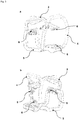
- Figure 1 shows some components of a preferred embodiment of the proposed protective device (1).
- the first handle (3) which in the context of the invention is preferably also referred to as the rear handle.
- the first handle (3) forms a top side of the protective device (1) with which the tool device (2), which is in the Figures 5 and 6th is represented, can be worn.
- the tool device (2) can be carried with the second handle (4) of the protective device (1), which is preferably also referred to as the front handle of the protective device (1).
- the handles (3, 4) form a frame-shaped device which can surround the rear part (13) of a tool device (2) when the tool device (2) and the protective device (1) are connected to one another.
- the frame-shaped device defines an interior space into which the rear part (13) of the tool device (2) can be inserted.
- the larger part of the frame-shaped device is at a distance from the tool device (2), so that there is only a few places where there is contact between the tool device (2) and the protective device (1).
- damping elements (6) are provided which are preferably designed to establish a connection between the tool device (2) and the protective device (1).
- the damping elements (6) cause a decoupling between the tool device (2) and the handles (3, 4) and the protective frame (5) of the protective device (1). This decoupling ensures in particular that only a few vibrations are transmitted from the tool device (2) to a user.
- the user grips the tool device (2) preferably at the handles (3, 4) of the protective device (1), so that vibration-related decoupling between the tool device (2) and the handles (3, 4) of the protective device ( 1) effectively prevents, in particular, the user's joints from being damaged by vibrations during long-term use of the tool device (2).
- the protective device (1) ensures effective protection of the tool device (2), for example in the event of a fall or other mechanical damage.
- the frame-shaped structure surrounds in particular the rear part (13) of the tool device (2), the main components (9, 10, 11) of the tool device (2) being in the rear area (13) of the tool device (2) in particular. These are, in particular, the motor (9), the transmission (10) and the at least one accumulator (11) of the tool device (2).
- the tool device (2) is preferably a battery-operated cut-off grinder, which is operated in particular with cut-off wheels that have a diameter of 300 mm or greater. Due to the vibration-related decoupling of the tool device (2) and protective device (1), a particularly simple, compact and robust construction of the tool device (2) can advantageously be made possible, the device (2) nevertheless having a low overall weight and with minimal transmission of hand-arm vibrations to the User can be operated.
- the invention enables a functional division of the individual components of the protective device (1) and the tool device (2), so that the system components, such as the accumulator (11), motor (9), gear (10), cutting disc (14), damping elements (6) and / or handles (3, 4) can be optimized for their respective task.
- Another advantage of the invention is that the provision of a functional unit (13) of the tool device (2) with the main components (9, 10, 11) on the one hand and the provision of the preferably decoupled protective device (1) with integrated handles (3, 4) on the other hand, a simple assembly of the proposed system can be made possible.
- the double L-shaped structure of the protective frame (5) can be seen in particular.
- the protective frame (5) is designed to surround an underside of the tool device (2) or to accommodate the main components (9, 10, 11) of the tool device (2).
- the longer side of the preferably L-shaped protective frame (5) forms the underside of the protective device (1), while the shorter side of the protective frame (5) forms its rear or rear side.
- FIG 2 shows how the components (3, 4, 5, 6) of the protective device (1) can be assembled to form a preferred embodiment of the protective device (1). It is shown in particular how the protective frame (5) can be connected to the handles (3, 4) so that the frame-shaped device is formed with the interior space for receiving the rear area (13) of the tool device (2). Furthermore, in Figure 2 Damping elements (6) and their possible arrangement in the frame-shaped structure are shown. The damping elements (6) are preferably located at those points on the frame-shaped structure at which the protective device (1) comes into contact with the tool device (2). In the context of the invention, these points are preferably referred to as contact points (7).
- the damping elements (6) or the points of contact (7) preferably form decoupling areas (8) where the vibration-related decoupling between the protective device (1) and the tool device (2) takes place.
- the parts of the figure 2a and 2b show different views of a preferred embodiment of the proposed protective device (1), the in the Figures 2a and 2b illustrated damping elements (6) are formed in particular from an elastic material. These damping elements (6) can preferably comprise rubber in particular.
- Figure 3 shows a preferred embodiment of the protective device (1) which comprises springs as damping elements (6).
- the springs can be designed as cylinder compression springs, for example.
- Parts of the figures 3a and 3b show different views of a preferred embodiment of the proposed protective device (1).
- Figure 4 shows a preferred embodiment of the protective device (1) with stop dampers (15).
- the stop dampers (15) can be arranged, for example, in a transition area between the rear handle (3) and the protective frame (5).
- the stop dampers (15) can also be arranged in a transition area between the front handle (4) and the protective frame (5).
- Figure 5 shows a preferred embodiment of the proposed system of protective device (1) and tool device (2).
- the protective device (1) preferably accommodates the rear part (13) of the tool device (2) with the main components such as the motor (9), gear (10) and accumulators (11).
- the accumulators (11) of the tool device (2) are shown in the removed state.
- the tool device (2) shown has, for example, two accumulators (11). However, only one accumulator (11) or more than two accumulators (11) can be provided in the tool device (2).
- the tool device (2) also has a front area (12).
- a work device (14) can be provided which, in the event that the tool device (2) is a cut-off grinder, is preferably a cutting disc.
- the diameter of the cutting disk (14) can be 300 mm or more in the case of the present invention.
- the cutting disc (14) is in Figure 5 not shown, but a blade guard with which it is usually prevented that particles fly off the cutting disc (14) in the direction of the user of the tool device (2).
- a first decoupling area (8a) can preferably be present in the transition area between the first handle (3) and the tool device (2).
- This first decoupling area (8a) can preferably comprise two damping elements (6).
- a second decoupling area (8b) is preferably in a transition area between the protective frame (5) and the second handle (4) of the protective device (1), preferably on the underside of the frame-shaped device.
- the second decoupling area (8b) preferably also comprises two damping elements (6).
- the third decoupling area (8c) preferably comprises a damping element (6) and is preferably in a transition area between the first handle (3) and the upper part of the protective frame (5).
Priority Applications (5)
| Application Number | Priority Date | Filing Date | Title |
|---|---|---|---|
| EP19171534.1A EP3733352A1 (fr) | 2019-04-29 | 2019-04-29 | Dispositif de protection pour un appareil-outil ainsi que système comprenant un dispositif de protection et un appareil-outil |
| PCT/EP2019/085668 WO2020221471A1 (fr) | 2019-04-29 | 2019-12-17 | Dispositif de protection destiné à une machine-outil, ainsi que système comprenant un dispositif de protection et une machine-outil |
| CN201980094130.7A CN113613845A (zh) | 2019-04-29 | 2019-12-17 | 用于动力工具的保护装置以及包括保护装置和动力工具的系统 |
| EP19818139.8A EP3962699B1 (fr) | 2019-04-29 | 2019-12-17 | Dispositif de protection pour un appareil-outil ainsi que système comprenant un dispositif de protection et un appareil-outil |
| US17/601,826 US20220176511A1 (en) | 2019-04-29 | 2019-12-17 | Protection device for a power tool, and system which comprises a protection device and a power tool |
Applications Claiming Priority (1)
| Application Number | Priority Date | Filing Date | Title |
|---|---|---|---|
| EP19171534.1A EP3733352A1 (fr) | 2019-04-29 | 2019-04-29 | Dispositif de protection pour un appareil-outil ainsi que système comprenant un dispositif de protection et un appareil-outil |
Publications (1)
| Publication Number | Publication Date |
|---|---|
| EP3733352A1 true EP3733352A1 (fr) | 2020-11-04 |
Family
ID=66323725
Family Applications (2)
| Application Number | Title | Priority Date | Filing Date |
|---|---|---|---|
| EP19171534.1A Withdrawn EP3733352A1 (fr) | 2019-04-29 | 2019-04-29 | Dispositif de protection pour un appareil-outil ainsi que système comprenant un dispositif de protection et un appareil-outil |
| EP19818139.8A Active EP3962699B1 (fr) | 2019-04-29 | 2019-12-17 | Dispositif de protection pour un appareil-outil ainsi que système comprenant un dispositif de protection et un appareil-outil |
Family Applications After (1)
| Application Number | Title | Priority Date | Filing Date |
|---|---|---|---|
| EP19818139.8A Active EP3962699B1 (fr) | 2019-04-29 | 2019-12-17 | Dispositif de protection pour un appareil-outil ainsi que système comprenant un dispositif de protection et un appareil-outil |
Country Status (4)
| Country | Link |
|---|---|
| US (1) | US20220176511A1 (fr) |
| EP (2) | EP3733352A1 (fr) |
| CN (1) | CN113613845A (fr) |
| WO (1) | WO2020221471A1 (fr) |
Cited By (4)
| Publication number | Priority date | Publication date | Assignee | Title |
|---|---|---|---|---|
| EP4008478A1 (fr) * | 2020-12-04 | 2022-06-08 | Hilti Aktiengesellschaft | Machine-outil doté d'un premier et d'un second accumulateur |
| EP4008477A1 (fr) * | 2020-12-04 | 2022-06-08 | Hilti Aktiengesellschaft | Machine-outil pourvu de refroidissement à air et procédé de refroidissement des composants d'une machine-outil |
| EP4008491A1 (fr) * | 2020-12-04 | 2022-06-08 | Hilti Aktiengesellschaft | Machine-outil doté d'une première poignée, d'une seconde poignée et d'un corps principal |
| EP4289562A1 (fr) * | 2022-06-07 | 2023-12-13 | Hilti Aktiengesellschaft | Machine-outil pourvue d'axes parallèles de sortie ou du moteur |
Families Citing this family (2)
| Publication number | Priority date | Publication date | Assignee | Title |
|---|---|---|---|---|
| US11919139B2 (en) * | 2021-04-28 | 2024-03-05 | Gripguard Inc. | Power tool fall protection device |
| CN115592622A (zh) * | 2021-07-08 | 2023-01-13 | 南京泉峰科技有限公司(Cn) | 电动工具 |
Citations (7)
| Publication number | Priority date | Publication date | Assignee | Title |
|---|---|---|---|---|
| US6112831A (en) * | 1995-07-13 | 2000-09-05 | Atlas Copco Berema Aktiebolag | Handle frame for percussive hand held machines |
| DE202005011592U1 (de) * | 2005-07-23 | 2006-11-23 | Dolmar Gmbh | Sicherheitsschalter für Trennschleifer |
| WO2007069946A1 (fr) * | 2005-12-14 | 2007-06-21 | Husqvarna Ab | Machine de travail portative |
| EP2080594A1 (fr) * | 2008-01-21 | 2009-07-22 | Makita Corporation | Outil électrique et protecteur pour outil électrique |
| US20100288907A1 (en) * | 2009-05-12 | 2010-11-18 | Makita Corporation | Floor plate |
| US20150026988A1 (en) * | 2013-07-27 | 2015-01-29 | Andreas Stihl Ag & Co. Kg | Hand-held work implement |
| US20160271782A1 (en) * | 2013-11-11 | 2016-09-22 | 3 Of Us Pty Ltd | Protective Tool Cover |
Family Cites Families (8)
| Publication number | Priority date | Publication date | Assignee | Title |
|---|---|---|---|---|
| US3152650A (en) * | 1962-05-15 | 1964-10-13 | R E Anderson | Handle frame for portable power tool |
| DE10260466B4 (de) * | 2002-12-21 | 2014-07-03 | Andreas Stihl Ag & Co. Kg | Handgeführtes Arbeitsgerät |
| EP1504655B1 (fr) * | 2003-08-04 | 2006-08-16 | BLACK & DECKER INC. | Assemblage de poignées pour outil motorisé |
| JP5457886B2 (ja) * | 2010-03-03 | 2014-04-02 | 株式会社マキタ | エンジンカッター |
| JP5598213B2 (ja) * | 2010-09-29 | 2014-10-01 | 日立工機株式会社 | 携帯型作業機 |
| US11338426B2 (en) * | 2015-11-02 | 2022-05-24 | Black & Decker, Inc. | Cordless power cutter |
| EP3173189A1 (fr) * | 2015-11-25 | 2017-05-31 | HILTI Aktiengesellschaft | Tronçonneuse portative manuelle |
| CN109716551A (zh) * | 2016-11-30 | 2019-05-03 | 里奇工具公司 | 混合动力工具 |
-
2019
- 2019-04-29 EP EP19171534.1A patent/EP3733352A1/fr not_active Withdrawn
- 2019-12-17 WO PCT/EP2019/085668 patent/WO2020221471A1/fr unknown
- 2019-12-17 CN CN201980094130.7A patent/CN113613845A/zh active Pending
- 2019-12-17 US US17/601,826 patent/US20220176511A1/en active Pending
- 2019-12-17 EP EP19818139.8A patent/EP3962699B1/fr active Active
Patent Citations (7)
| Publication number | Priority date | Publication date | Assignee | Title |
|---|---|---|---|---|
| US6112831A (en) * | 1995-07-13 | 2000-09-05 | Atlas Copco Berema Aktiebolag | Handle frame for percussive hand held machines |
| DE202005011592U1 (de) * | 2005-07-23 | 2006-11-23 | Dolmar Gmbh | Sicherheitsschalter für Trennschleifer |
| WO2007069946A1 (fr) * | 2005-12-14 | 2007-06-21 | Husqvarna Ab | Machine de travail portative |
| EP2080594A1 (fr) * | 2008-01-21 | 2009-07-22 | Makita Corporation | Outil électrique et protecteur pour outil électrique |
| US20100288907A1 (en) * | 2009-05-12 | 2010-11-18 | Makita Corporation | Floor plate |
| US20150026988A1 (en) * | 2013-07-27 | 2015-01-29 | Andreas Stihl Ag & Co. Kg | Hand-held work implement |
| US20160271782A1 (en) * | 2013-11-11 | 2016-09-22 | 3 Of Us Pty Ltd | Protective Tool Cover |
Cited By (8)
| Publication number | Priority date | Publication date | Assignee | Title |
|---|---|---|---|---|
| EP4008478A1 (fr) * | 2020-12-04 | 2022-06-08 | Hilti Aktiengesellschaft | Machine-outil doté d'un premier et d'un second accumulateur |
| EP4008477A1 (fr) * | 2020-12-04 | 2022-06-08 | Hilti Aktiengesellschaft | Machine-outil pourvu de refroidissement à air et procédé de refroidissement des composants d'une machine-outil |
| EP4008491A1 (fr) * | 2020-12-04 | 2022-06-08 | Hilti Aktiengesellschaft | Machine-outil doté d'une première poignée, d'une seconde poignée et d'un corps principal |
| WO2022117335A1 (fr) * | 2020-12-04 | 2022-06-09 | Hilti Aktiengesellschaft | Machine-outil ayant une première poignée, une seconde poignée et un corps principal |
| WO2022117336A1 (fr) * | 2020-12-04 | 2022-06-09 | Hilti Aktiengesellschaft | Machine-outil à refroidissement par air et procédé de refroidissement d'éléments de machine-outil |
| WO2022117337A1 (fr) * | 2020-12-04 | 2022-06-09 | Hilti Aktiengesellschaft | Outil électrique doté d'une première et d'une seconde batterie rechargeable |
| EP4289562A1 (fr) * | 2022-06-07 | 2023-12-13 | Hilti Aktiengesellschaft | Machine-outil pourvue d'axes parallèles de sortie ou du moteur |
| WO2023237363A1 (fr) * | 2022-06-07 | 2023-12-14 | Hilti Aktiengesellschaft | Machine-outil à axe de sortie et axe de moteur parallèles |
Also Published As
| Publication number | Publication date |
|---|---|
| CN113613845A (zh) | 2021-11-05 |
| EP3962699B1 (fr) | 2024-03-13 |
| WO2020221471A1 (fr) | 2020-11-05 |
| EP3962699A1 (fr) | 2022-03-09 |
| US20220176511A1 (en) | 2022-06-09 |
Similar Documents
| Publication | Publication Date | Title |
|---|---|---|
| EP3962699B1 (fr) | Dispositif de protection pour un appareil-outil ainsi que système comprenant un dispositif de protection et un appareil-outil | |
| EP1844646B1 (fr) | Taille-haie | |
| EP2841236B1 (fr) | Machine-outil portable dotée d'un boîtier externe | |
| EP1620233B1 (fr) | Machine-outil manuelle electrique comportant un bloc d'accumulateur | |
| DE10260466B4 (de) | Handgeführtes Arbeitsgerät | |
| EP2841237B1 (fr) | Machine-outil pouvant être guidée manuellement et comportant un carter | |
| EP2234776B1 (fr) | Outil électrique à main à alimentation par accumulateur | |
| EP2629933B1 (fr) | Outil de travail notamment outil électrique | |
| DE102018109295A1 (de) | Elektrisches Gerät | |
| DE19919385A1 (de) | Motorgetriebenes Arbeitsgerät | |
| EP2244862B1 (fr) | Poignée isolée des vibrations | |
| EP3725949B1 (fr) | Appareil outil guidé à la main pourvu de support non couplé de barre d'attelage | |
| DE202013103750U1 (de) | Elektrische Bearbeitungsmaschine und elektrisches Bearbeitungsmaschinensystem | |
| DE102005043118A1 (de) | Arbeitsgerät | |
| EP3533562B1 (fr) | Appareil de travail à commande manuelle | |
| DE69808662T3 (de) | Tragbare landwirtschaftliche maschine mit schwingungsdämpfung und schutz für den bediener | |
| WO2007080021A1 (fr) | Réduction des vibrations dans des outils électriques | |
| DE4416044C2 (de) | Schwingungsdämpfende Lagerung für motorgetriebene, handgehaltene Geräte | |
| WO2022117337A1 (fr) | Outil électrique doté d'une première et d'une seconde batterie rechargeable | |
| EP0446681B1 (fr) | Dispositif amortisseur de vibrations pour oscillations verticales | |
| EP4183518A1 (fr) | Machine-outil dotée d'un moteur disposé le long d'un axe de coupe | |
| DE1582863A1 (de) | Schneidvorrichtung | |
| EP4008491A1 (fr) | Machine-outil doté d'une première poignée, d'une seconde poignée et d'un corps principal | |
| DE102021209180A1 (de) | Handgehaltenes Bearbeitungsgerät mit einer Aufhängevorrichtung | |
| EP4289562A1 (fr) | Machine-outil pourvue d'axes parallèles de sortie ou du moteur |
Legal Events
| Date | Code | Title | Description |
|---|---|---|---|
| PUAI | Public reference made under article 153(3) epc to a published international application that has entered the european phase |
Free format text: ORIGINAL CODE: 0009012 |
|
| STAA | Information on the status of an ep patent application or granted ep patent |
Free format text: STATUS: THE APPLICATION HAS BEEN PUBLISHED |
|
| AK | Designated contracting states |
Kind code of ref document: A1 Designated state(s): AL AT BE BG CH CY CZ DE DK EE ES FI FR GB GR HR HU IE IS IT LI LT LU LV MC MK MT NL NO PL PT RO RS SE SI SK SM TR |
|
| AX | Request for extension of the european patent |
Extension state: BA ME |
|
| STAA | Information on the status of an ep patent application or granted ep patent |
Free format text: STATUS: THE APPLICATION IS DEEMED TO BE WITHDRAWN |
|
| 18D | Application deemed to be withdrawn |
Effective date: 20210505 |