EP2080594A1 - Outil électrique et protecteur pour outil électrique - Google Patents
Outil électrique et protecteur pour outil électrique Download PDFInfo
- Publication number
- EP2080594A1 EP2080594A1 EP08001011A EP08001011A EP2080594A1 EP 2080594 A1 EP2080594 A1 EP 2080594A1 EP 08001011 A EP08001011 A EP 08001011A EP 08001011 A EP08001011 A EP 08001011A EP 2080594 A1 EP2080594 A1 EP 2080594A1
- Authority
- EP
- European Patent Office
- Prior art keywords
- battery pack
- protector
- battery
- tool body
- tool
- Prior art date
- Legal status (The legal status is an assumption and is not a legal conclusion. Google has not performed a legal analysis and makes no representation as to the accuracy of the status listed.)
- Granted
Links
- 230000001012 protector Effects 0.000 title claims abstract description 96
- 230000005540 biological transmission Effects 0.000 claims abstract 2
- 230000002452 interceptive effect Effects 0.000 claims description 2
- 238000000034 method Methods 0.000 abstract description 13
- 238000010276 construction Methods 0.000 description 14
- 210000003811 finger Anatomy 0.000 description 11
- 239000002184 metal Substances 0.000 description 8
- 210000003813 thumb Anatomy 0.000 description 4
- 230000001681 protective effect Effects 0.000 description 3
- 238000005553 drilling Methods 0.000 description 2
- 238000003780 insertion Methods 0.000 description 2
- 230000037431 insertion Effects 0.000 description 2
- 238000004519 manufacturing process Methods 0.000 description 2
- 238000000465 moulding Methods 0.000 description 2
- 230000007423 decrease Effects 0.000 description 1
- 230000003247 decreasing effect Effects 0.000 description 1
- 230000005489 elastic deformation Effects 0.000 description 1
- 238000010068 moulding (rubber) Methods 0.000 description 1
- 238000003825 pressing Methods 0.000 description 1
- 239000011347 resin Substances 0.000 description 1
- 229920005989 resin Polymers 0.000 description 1
- 229920003051 synthetic elastomer Polymers 0.000 description 1
- 239000005061 synthetic rubber Substances 0.000 description 1
Images


Classifications
-
- B—PERFORMING OPERATIONS; TRANSPORTING
- B25—HAND TOOLS; PORTABLE POWER-DRIVEN TOOLS; MANIPULATORS
- B25F—COMBINATION OR MULTI-PURPOSE TOOLS NOT OTHERWISE PROVIDED FOR; DETAILS OR COMPONENTS OF PORTABLE POWER-DRIVEN TOOLS NOT PARTICULARLY RELATED TO THE OPERATIONS PERFORMED AND NOT OTHERWISE PROVIDED FOR
- B25F5/00—Details or components of portable power-driven tools not particularly related to the operations performed and not otherwise provided for
- B25F5/02—Construction of casings, bodies or handles
-
- B—PERFORMING OPERATIONS; TRANSPORTING
- B25—HAND TOOLS; PORTABLE POWER-DRIVEN TOOLS; MANIPULATORS
- B25F—COMBINATION OR MULTI-PURPOSE TOOLS NOT OTHERWISE PROVIDED FOR; DETAILS OR COMPONENTS OF PORTABLE POWER-DRIVEN TOOLS NOT PARTICULARLY RELATED TO THE OPERATIONS PERFORMED AND NOT OTHERWISE PROVIDED FOR
- B25F5/00—Details or components of portable power-driven tools not particularly related to the operations performed and not otherwise provided for
- B25F5/006—Vibration damping means
Definitions
- the present invention relates to a battery-powered power tool and more particularly, to a technique for protecting a battery pack of the power tooL
- a known battery-powered power tool is provided with a protective provision to protect a battery pack against impact when the power tool is struck against something or dropped during use or carry.
- a power tool is disclosed, for example, in EP 1516702 .
- a cushioning protection member mainly comprising an elastic element is directly provided on the battery pack itself and protects the battery pack against impact.
- a cushioning member as a protective member is directly mounted in the known art, sufficient impact absorbing effectiveness cannot be obtained.
- a representative power tool includes a tool body to which a tool bit is coupled, a driving motor disposed within the tool body, and a battery pack that supplies driving current to the driving motor.
- the battery pack is removably mounted to the tool body and placed on the outside of the tool body in an exposed state.
- the representative power tool includes a protector that is removably mounted to the tool body and protects the battery pack.
- the protector is provided as a kind of adapter.
- the protector includes a battery pack protection area that protects the battery pack mounted to the tool body when the protector is mounted to the tool body.
- the battery pack protection area is disposed on at least part of the outer surface of the battery pack with a clearance therebetween and prevents an external force upon the battery pack protection area from being transmitted to the battery pack.
- the battery pack protection area may typically include a frame member that is disposed to cover the outer surface of the battery pack at least in part or in entirety
- This frame member may be preferably formed by rigid metal sheet, or by an elastic element (rubber molding) into which a sheet metal is inserted, or by a resin molding into which a sheet metal is inserted.
- the protector is provided with the battery pack protection area which is spaced apart from the associated outer surface of the battery pack.
- the protector is removably mounted to the tool body, only the protector can be replaced with a new one if the protector is broken. Further, depending on the operation modes of the power tool, the processing operation can be performed with the protector being removed from the power tool.
- FIG. 1 is a perspective, external view showing a rechargeable vibration driver drill 100, which is used for screw-tightening and drilling operations, as a representative example of a power tool according to the embodiment of the present invention.
- the representative rechargeable vibration driver drill 100 includes a body 101 and a driver bit which performs a screw-tightening operation of tightening various kinds of screws or a drill bit for drilling operation (which is not shown).
- the driver bit or drill bit is detachably coupled to the tip end region of the body 101.
- the body 101 and the driver bit or drill bit are the features that correspond to the "tool body” and the "tool bit", respectively, according to this invention.
- the tip end side (bit side) of the body 101 is taken as the front side, and the opposite side as the rear side.
- the body 101 includes a motor housing 103, a gear housing 105 and a handgrip 107.
- the motor housing 103 houses a driving motor (not shown) that drives a bit.
- a trigger 107a for actuating a power switch of the driving motor is mounted on the handgrip 107.
- the gear housing 105 houses a power transmitting mechanism (not shown) for transmitting the rotating output of the driving motor.
- the vibration driver drill 100 is T-shaped, with the handgrip 107 extending from generally the middle of the body 101 in its longitudinal direction and extending downward in a direction that intersects with the longitudinal direction of the body 101.
- a battery holder 109 is formed on the lower end or extending end of the handgrip 107.
- the battery holder 109 has a predetermined plane area wider than the sectional area of the handgrip 107.
- a battery pack 111 for supplying driving current to the driving motor is mounted on the underside of the battery holder 109.
- the handgrip 107 and the battery holder 109 are the features that correspond to the "grip" and the "extending end", respectively, according to this invention.
- the battery pack 11 includes a battery case 113 having a generally rectangular, open-topped box-like shape, a plurality of cells (not shown) housed in the battery case 113, and a removable battery cover 115 for covering the open top of the battery case 113.
- the battery pack 111 is detachably mounted to the battery holder 109 by sliding the battery pack 111 horizontally in the longitudinal direction of the body 101.
- a mounting guide (not shown) is provided on the top of the battery pack 111 or on the battery cover 115, and a locking device (not shown) is provided on the inner surface of the battery cover 115.
- the mounting guide serves as a means for guiding the battery pack 111 to be slid backward from the front of the battery holder 109 so as to be mounted onto the battery holder 109 and also serves as a means for preventing the battery pack 111 from falling off the battery holder 109.
- the locking device includes a hook provided on the battery pack 111 and an engagement portion formed on the battery holder 109.
- the locking device locks the battery pack 111 by engagement of the hook and the engagement portion when the battery pack 111 is slid from before backward and mounted on the battery holder 109.
- the battery pack 111 is prevented from sliding forward (in the direction of removal) and becoming detached from the battery bolder 109.
- the book is configured to constantly apply a biasing force of a spring in the direction of engagement.
- a lock release lever 117 is disposed on a front 111a of the battery pack 111 (the front of the battery cover 115) and can be pressed from the outside to release the lock of the locking device.
- the lock release lever 117 is a feature that corresponds to the "operating part" according to the present invention.
- the battery pack 111 attached to the battery holder 109 is kept exposed on the outside of the body 103, except its upper surface or mounting surface for mounting to the battery bolder 109.
- FIG. 2 is a perspective view showing the entire battery protector 121.
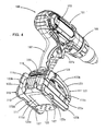
- FIGS. 3 and 4 show the battery protector 121 attached to the vibration driver drill 100.
- the battery protector 121 is removably mounted to the battery holder 109, and the mounting structure for mounting the battery protector will be described below.
- the battery protector 121 is generally U-shaped as viewed from the front, including a pair of right and left side frames 123 extending in the longitudinal direction of the body 101 and a connecting plate 125 that connects the side frames 123 on the bottom side.
- the battery protector 121 has a frame structure having open front, back and top and closed sides and bottom
- the side frames 123 and the connecting plate 125 are features that correspond to the "battery pack protection area" according to the present invention.
- Each of the side frames 123 includes a rigid element 123a made of sheet metal and an elastically deformable elastic element 123b made of synthetic rubber.
- the rigid element 123a has a generally rectangular frame-like shape having an opening in the center, as viewed from the side.
- the elastic element 123b covers upper and lower frame regions of the rigid element 123a and is formed by insert molding.
- Each of the side frames 123 is higher in the vertical direction and longer in the longitudinal direction than the battery pack 111.
- a protruding piece 123c is integrally formed on the lower frame portion of each of the rigid elements 123a and extends horizontally inward from the front region (in the longitudinal direction) of the lower frame portion.
- the connecting plate 125 of sheet metal is rotatably connected to the protruding piece 123c by a connecting pin 127.
- a slit-like engagement groove 109a is formed in a rear portion of each of the right and left sides of the battery holder 109 and extends horizontally in the longitudinal direction. Further, a mounting portion 109b having a screw hole is formed slightly below the engagement groove 109a.
- the engagement groove 109a and the mounting portion 109b are provided as a mounting portion for mounting existing attachments, namely a hook (not shown) which is used to book the vibration driver drill 100 onto a waist belt of the user, or a bit holder (not shown) for holding spare driver bits.
- this mounting portion is utilized to mount the battery protector 121.
- This mounting portion is a feature that corresponds to the "mounting portion" according to the present invention.
- an engagement piece 123d is integrally formed on the upper frame portion of the rigid element 123a of each of the side frames 123 and extends horizontally inward from the rear region (in the longitudinal direction) of the upper frame portion. Further, a mounting hole 123e is formed slightly below the engagement piece 123d and extends through the upper frame portion in the lateral direction. The right and left engagement pieces 123d are inserted into the associated engagement grooves 109a of the battery holder 109 and thereby serve as a means for positioning and temporarily fixing the battery protector 121 to the battery holder 109 when the battery protector 121 is mounted to the battery holder 109.
- the battery protector 121 having the above-described construction is mounted to the battery holder 109 in the following procedures. First, the side frames 123 are rotated on the connecting pin 127 in a direction that increases the distance between the side frames 123 on the rear side. In this state, the side frames 123 are then positioned to face the sides 111b of the battery pack 111. Thereafter, the side frames 123 are rotated back on the connecting pin 127 in a direction that decreases the distance between the side frames 123 on the rear side. In this manner, the engagement pieces 123d are fitted into the associated engagement grooves 109a of the battery holder 109. Thus, the battery protector 121 is positioned and temporarily fixed to the battery holder 109.
- the mounting screws 129 are passed through the mounting holes 123e and driven into the screw holes of the protector mounting portions 109b.
- the battery protector 121 can be mounted to the battery holder 109. Further, the battery protector 121 can be removed from the battery holder 109 by reversing the above-described mounting procedure.
- FIGS. 3 and 4 show the battery protector 121 attached to the battery holder 109.
- the inner faces of the side frames 123 of the battery protector 121 are located along the associated sides 111b of the battery pack 111 with a clearance therebetween.
- the upper face of the connecting plate 125 is located under a bottom 111d of the battery pack 111 with a clearance therebetween.
- the front end portions of the side frames 123 protrude a predetermined distance forward from the front 111a of the battery pack 111, and the rear end portions of the side frames 123 protrude a predetermined distance rearward from a back 111c of the battery pack 111. Further, the lower end portions of the side frames 123 protrude a predetermined distance downward from the bottom 111d of the battery pack 111.
- a front portion of the protector 121 which faces the front 111 a of the battery pack 111 on which the lock release lever 117 is mounted and a rear portion of the protector 121 which faces the back 111c of the battery pack 111 are open.
- the user's fingers holding the battery pack 111 can pass through the open front and rear portions together with the battery pack 111 when the battery pack 111 is attached to and removed from the battery holder 109.
- the open front portion and the open rear portion are designated by symbols "FO” and "RO", respectively.
- the user when removing the battery pack 111 from the battery holder 109 in order, for example, to charge the battery pack 111, the user insert the thumb into the open front portion FO and the other fingers into the open rear portion RO. Then, the lock release lever 117 is pressed with the thumb in order to release the lock of the battery pack 111 by the lock device with respect to the battery holder 109. In this state, the battery pack 111 is slid forward while holding the back 111c ofthe battery pack 111 with the fingers other than the thumb. Thus, the battery pack 111 can be removed from the battery holder 109 via the open front portion FO of the battery protector 121 without interfering with the battery protector 121.
- the lock device When the battery pack 111 is in a position a predetermined distance away from its mounting position, the lock device is kept in the lock-released state even if the lock release lever 117 is released. Therefore, it is not necessary to keep pressing the lock release lever 117 until the battery pack is completely removed. Thus, the user is allowed to once release the fingers from the battery pack 111 and then hold it again in the process of its removal.
- the fingers other than the thumb are initially placed to cross the connecting plate 125.
- the fingers can be released from the battery pack 111 and then held again in the process of its removal. Further, the battery pack 111 can be attached to the battery holder 109 by reversing the above-described removing procedure.
- the battery protector 121 can be left attached to the battery holder 109 while the battery pack 111 is attached to and removed from the battery holder 109.
- the open front and rear portions FO, RO of the battery protector 121 are features that correspond to the "open region" according to the present invention.
- the vibration driver drill 100 is provided with the battery protector 121 for protecting the battery pack 111.
- the inner faces of the right and left side frames 123 of the battery protector 121 are located along the associated sides 111b of the battery pack 111 with a clearance of certain distances. Further, the front, rear and lower end portions of the side frames 123 protrude outward from the front 111a, the back 111c and the bottom 111d of the battery pack 111, respectively.
- the vibration driver drill 100 is dropped on the ground during use or carry, either one or both of the frames 123 hit the ground, so that not only the sides 111 b but also the front 111a, the back 111c and the bottom 111d of the battery protector 121 can be protected from directly hitting the ground.
- the same protective effect can be obtained as a construction in which the entire outside surface of the battery pack 111 is covered.
- the side frames 123 are spaced apart from the associated sides 111b of the battery pack 111. Therefore, an external force (impact force) upon the side frames 123 can be prevented from being transmitted to the battery pack 111.
- the battery protector 121 can effectively protect the battery pack 111 against impact when the vibration driver drill 100 is dropped or struck against something during use or carry.
- the rigid element 123a made of sheet metal and the elastic element 123b covering the rigid element 123a form each of the side frames 123. Therefore, the side frames 123 are capable of cushioning the impact of hitting the ground or any other object while maintaining a predetermined rigidity. Thus, the protection performance for protecting the battery pack 111 can be further improved.
- the battery protector 121 can be removably attached to the battery holder 109 formed on the tool body side. Therefore, in contrast to the construction in which a cushioning element is directly provided on the battery pack 111, if the battery protector 121 is broken, only the broken battery protector 121 can be replaced with a new one, and thus the whole battery pack itself need not be replaced with a new one.
- the engagement groove 109a and the mounting portion 109b of the battery holder 109 form a mounting portion for mounting attachments, namely a hook or a bit holder.
- the existing mounting portion is utilized to mount the battery protector 121.
- each of the side frames 123 of the battery protector 121 is formed with the engagement piece 123d that can be engaged in the engagement groove 109a and the mounting hole 123e for the mounting screw 129, so that the battery protector 121 can be attached to the battery holder 109.
- the mounting structure for the battery protector 121 can be efficiently provided.
- either the attachment or the battery protector 121 can be selectively mounted to the attachment mounting portion.
- the side frames 123 can be rotated horizontally on the connecting pin 127, so that the distance between the side frames 123 on the side of the engagement pieces 123d can be increased or decreased.
- the engagement pieces 123d can be easily engaged in or disengaged from the engagement grooves 109a when the battery protector 121 is attached to or removed from the battery holder 109. Therefore, this construction is effective in work simplification of mounting and removing the battery protector 121.
- the battery protector 121 is generally U-sbaped as viewed from the front, including a pair ofright and left side frames 123 extending in the longitudinal direction ofthe body 101 and a connecting plate 125 that connects the side frames 123 on the bottom side.
- the battery protector 121 is configured to have open front and back located in the direction of attachment and removal of the battery pack 111. With this configuration, the battery protector 121 can be left attached to the battery holder 109 while the battery pack 111 is attached to and removed from the battery holder 109. Therefore, ease of operation of mounting and removing the battery pack 111 can be improved.
- each of the right and left side frames 123 is formed by only the rigid element 123a of the metal sheet.
- the connecting plate 125 is integrally formed with the side frames 123 and extends between the lower frame portions of the side frames 123.
- the side frames 123 are connected to each other by the connecting plate 125.
- the engagement piece 123d and the mounting hole 123e for mounting the battery protector 121 to the battery holder 109 are formed in the upper frame portion of each of the side frames 123.
- the engagement pieces 123d are engaged in the associated engagement groove 109a which are formed in the battery holder 109 on the lower end ofthe handgrip 107, and the mounting screws 129 are inserted through the mounting holes 123e and driven into the screw holes of the mounting portions 109b.
- the distance between the upper frame portions of the side frames 123 can be increased such that the upper frame portions are moved away from each other by utilizing the elastic deformation of the connecting plate 125. Therefore, the engagement pieces 123d can be inserted into and removed from the associated engagement groove 109a without any trouble.
- the battery protector 121 is positioned and temporarily fixed to the battery holder 109 by the engagement pieces 123d, so that the screw-tightening operation by using the mounting screws 129 can be facilitated. Further, the battery protector 121 is manufactured from only the rigid element 123a or metal sheet. This is effective in realizing simplification of the structure and weigh reduction while ensuring a predetermined rigidity, and also in reduction of the manufacturing costs.
- the power tool is describe as being of the slide type in which the battery pack 111 is mounted to and removed from the battery holder 109 by moving in a direction that intersects with the extending direction of the handgrip 107.
- this invention can also be applied to a power tool of an insertion type in which the battery pack is mounted and removed by moving the battery pack 111 in the extending direction of the handgrip 107.
- the battery protector 121 for protecting the insertion-type battery pack has an open side that faces one side (for example, the front) of the outer surface of the battery pack 111 on which at least the lock release lever 117 of the locking device that locks the battery pack 111 to the battery holder 109 is provided.
- the battery protector 121 also has another open side which faces the bottom of the battery pack 111 in the direction of removal of the battery pack 111.
- frame portions are provided as a battery pack protection area.
- the battery protector 121 can be left attached to the battery holder 109 while the user operates the lock release lever 117 in order to allow removal of the battery pack and then withdraws the battery pack 111 while holding the front and the back of the battery pack 111 by the fingers inserted through the open sides.
- the battery pack 111 can also be mounted while the battery protector 121 is left attached to the battery holder 109.
- the user operates the lock release lever 117 with the finger to allow the battery pack 111 to be removed, and while keeping this state, the user holds the battery pack 111 and removes the battery pack 111 from the battery holder 109.
- the fingers holding the battery pack 111 are placed to cross the connecting plate 125.
- the battery protector 121 may be configured such that the fingers holding the battery pack 111 are not placed to cross the connecting plate 125, or specifically such that the fingers can be passed through the open area without interference (without need of holding the battery pack 111 again after once released).
- the construction in which the side frames 123 rotate horizontally via the connecting pins 127 may be changed into the construction as described in the second embodiment in which the side frames 123 are integrally formed with the connecting plate 125.
- the mounting structure for mounting the battery protector 121 to the battery holder 109 may be changed to a different one from that shown in the drawings.
- the side frames 123 may be changed to a construction not having an opening in the center, such as a construction in which a flat plate forms the side frames 123 and entirely covers the side surfaces of the battery pack 111.
- the rechargeable vibration driver drill 100 is described as a representative example of the power tool, but it is not limited to the vibration driver drill 100. The present invention can be widely applied to any rechargeable power tools having a battery pack mounted externally in an exposed state.
Priority Applications (1)
| Application Number | Priority Date | Filing Date | Title |
|---|---|---|---|
| EP08001011A EP2080594B1 (fr) | 2008-01-21 | 2008-01-21 | Outil électrique et protecteur pour outil électrique |
Applications Claiming Priority (1)
| Application Number | Priority Date | Filing Date | Title |
|---|---|---|---|
| EP08001011A EP2080594B1 (fr) | 2008-01-21 | 2008-01-21 | Outil électrique et protecteur pour outil électrique |
Publications (2)
| Publication Number | Publication Date |
|---|---|
| EP2080594A1 true EP2080594A1 (fr) | 2009-07-22 |
| EP2080594B1 EP2080594B1 (fr) | 2013-04-03 |
Family
ID=39323021
Family Applications (1)
| Application Number | Title | Priority Date | Filing Date |
|---|---|---|---|
| EP08001011A Active EP2080594B1 (fr) | 2008-01-21 | 2008-01-21 | Outil électrique et protecteur pour outil électrique |
Country Status (1)
| Country | Link |
|---|---|
| EP (1) | EP2080594B1 (fr) |
Cited By (8)
| Publication number | Priority date | Publication date | Assignee | Title |
|---|---|---|---|---|
| WO2011110188A1 (fr) * | 2010-03-06 | 2011-09-15 | Husqvarna Ab | Outil à moteur comportant un boîtier protecteur pour batterie |
| WO2011110187A1 (fr) * | 2010-03-06 | 2011-09-15 | Husqvarna Ab | Outil à moteur comportant un protecteur de batterie |
| US9224995B2 (en) | 2010-03-06 | 2015-12-29 | Husqvarna Ab | Battery powered tool and battery pack for a battery powered tool |
| EP3085499A1 (fr) * | 2015-04-24 | 2016-10-26 | HILTI Aktiengesellschaft | Coque de protection de batterie d'outil |
| US10105832B2 (en) | 2010-07-02 | 2018-10-23 | Husqvarna Ab | Battery powered tool |
| EP3653344A1 (fr) * | 2018-11-13 | 2020-05-20 | Hilti Aktiengesellschaft | Machine-outil portative fonctionnant sur accumulateur |
| EP3733352A1 (fr) * | 2019-04-29 | 2020-11-04 | Hilti Aktiengesellschaft | Dispositif de protection pour un appareil-outil ainsi que système comprenant un dispositif de protection et un appareil-outil |
| EP3875223A1 (fr) * | 2020-03-02 | 2021-09-08 | Hilti Aktiengesellschaft | Machine-outil pourvu de dispositif d'arceau de sûreté pour accumulateurs |
Citations (3)
| Publication number | Priority date | Publication date | Assignee | Title |
|---|---|---|---|---|
| US5401591A (en) * | 1993-11-10 | 1995-03-28 | Intermec Corporation | Shock-mitigating battery boot |
| DE20117889U1 (de) * | 2001-11-02 | 2002-01-24 | Hilti Ag | Akkubetriebenes Schraubgerät |
| EP1516702A2 (fr) | 2003-09-15 | 2005-03-23 | Techtronic Industries Co., Ltd. | Ensemble-batterie amovible pour outil électrique portatif |
-
2008
- 2008-01-21 EP EP08001011A patent/EP2080594B1/fr active Active
Patent Citations (3)
| Publication number | Priority date | Publication date | Assignee | Title |
|---|---|---|---|---|
| US5401591A (en) * | 1993-11-10 | 1995-03-28 | Intermec Corporation | Shock-mitigating battery boot |
| DE20117889U1 (de) * | 2001-11-02 | 2002-01-24 | Hilti Ag | Akkubetriebenes Schraubgerät |
| EP1516702A2 (fr) | 2003-09-15 | 2005-03-23 | Techtronic Industries Co., Ltd. | Ensemble-batterie amovible pour outil électrique portatif |
Cited By (10)
| Publication number | Priority date | Publication date | Assignee | Title |
|---|---|---|---|---|
| WO2011110188A1 (fr) * | 2010-03-06 | 2011-09-15 | Husqvarna Ab | Outil à moteur comportant un boîtier protecteur pour batterie |
| WO2011110187A1 (fr) * | 2010-03-06 | 2011-09-15 | Husqvarna Ab | Outil à moteur comportant un protecteur de batterie |
| US9224995B2 (en) | 2010-03-06 | 2015-12-29 | Husqvarna Ab | Battery powered tool and battery pack for a battery powered tool |
| US10105832B2 (en) | 2010-07-02 | 2018-10-23 | Husqvarna Ab | Battery powered tool |
| EP3085499A1 (fr) * | 2015-04-24 | 2016-10-26 | HILTI Aktiengesellschaft | Coque de protection de batterie d'outil |
| EP3653344A1 (fr) * | 2018-11-13 | 2020-05-20 | Hilti Aktiengesellschaft | Machine-outil portative fonctionnant sur accumulateur |
| EP3733352A1 (fr) * | 2019-04-29 | 2020-11-04 | Hilti Aktiengesellschaft | Dispositif de protection pour un appareil-outil ainsi que système comprenant un dispositif de protection et un appareil-outil |
| WO2020221471A1 (fr) * | 2019-04-29 | 2020-11-05 | Hilti Aktiengesellschaft | Dispositif de protection destiné à une machine-outil, ainsi que système comprenant un dispositif de protection et une machine-outil |
| EP3875223A1 (fr) * | 2020-03-02 | 2021-09-08 | Hilti Aktiengesellschaft | Machine-outil pourvu de dispositif d'arceau de sûreté pour accumulateurs |
| WO2021175572A1 (fr) * | 2020-03-02 | 2021-09-10 | Hilti Aktiengesellschaft | Machine-outil comprenant un agencement de dispositif de sécurité pour batteries rechargeables |
Also Published As
| Publication number | Publication date |
|---|---|
| EP2080594B1 (fr) | 2013-04-03 |
Similar Documents
| Publication | Publication Date | Title |
|---|---|---|
| US8148000B2 (en) | Power tool and protector for power tool | |
| EP2080594B1 (fr) | Outil électrique et protecteur pour outil électrique | |
| US11148272B2 (en) | Power tool | |
| EP2596917B1 (fr) | Manche d'outil électrique à main | |
| EP2596918B1 (fr) | Outils électriques | |
| US7331685B2 (en) | Nailer with an illumination device | |
| US6189217B1 (en) | Power saw having blade storage chamber | |
| US9502801B2 (en) | Electric apparatus having a plate-shaped male terminal with a level difference in its thickness direction | |
| US20070034397A1 (en) | Hand-held power tool with vibration-reducing means | |
| AU2005100996A4 (en) | Power Tool with a Tool Storage | |
| DE60011318D1 (de) | Batteriebetriebene Handwerkzeugmaschine | |
| JP2013086228A (ja) | 電動工具 | |
| EP2407264A1 (fr) | Scie modulaire | |
| US9876201B2 (en) | Electric working machine and electric working machine system | |
| JP5541444B2 (ja) | 電動工具 | |
| EP1679144A1 (fr) | Outil motorisé portatif avec moyens de stockage pour outils | |
| JP2004299050A (ja) | 手持式電動工具 | |
| US20080245198A1 (en) | Power tool with a blade storage container | |
| CN210705167U (zh) | 链锯 | |
| US20230063991A1 (en) | Power tool having a protective guard-bracket device for rechargeable batteries | |
| US11897114B1 (en) | Accessory storage location for power tool | |
| CN215093263U (zh) | 电动工具 | |
| CN115519160A (zh) | 作业机 | |
| US20200384549A1 (en) | Ergonomic attachment for an angular drill assembly | |
| JP3576134B2 (ja) | 携帯用電気丸鋸用平行定規 |
Legal Events
| Date | Code | Title | Description |
|---|---|---|---|
| PUAI | Public reference made under article 153(3) epc to a published international application that has entered the european phase |
Free format text: ORIGINAL CODE: 0009012 |
|
| AK | Designated contracting states |
Kind code of ref document: A1 Designated state(s): AT BE BG CH CY CZ DE DK EE ES FI FR GB GR HR HU IE IS IT LI LT LU LV MC MT NL NO PL PT RO SE SI SK TR |
|
| AX | Request for extension of the european patent |
Extension state: AL BA MK RS |
|
| 17P | Request for examination filed |
Effective date: 20091223 |
|
| AKX | Designation fees paid |
Designated state(s): DE FR GB |
|
| GRAP | Despatch of communication of intention to grant a patent |
Free format text: ORIGINAL CODE: EPIDOSNIGR1 |
|
| GRAS | Grant fee paid |
Free format text: ORIGINAL CODE: EPIDOSNIGR3 |
|
| GRAA | (expected) grant |
Free format text: ORIGINAL CODE: 0009210 |
|
| AK | Designated contracting states |
Kind code of ref document: B1 Designated state(s): DE FR GB |
|
| REG | Reference to a national code |
Ref country code: GB Ref legal event code: FG4D |
|
| REG | Reference to a national code |
Ref country code: DE Ref legal event code: R096 Ref document number: 602008023381 Country of ref document: DE Effective date: 20130529 |
|
| PLBE | No opposition filed within time limit |
Free format text: ORIGINAL CODE: 0009261 |
|
| STAA | Information on the status of an ep patent application or granted ep patent |
Free format text: STATUS: NO OPPOSITION FILED WITHIN TIME LIMIT |
|
| 26N | No opposition filed |
Effective date: 20140106 |
|
| REG | Reference to a national code |
Ref country code: DE Ref legal event code: R097 Ref document number: 602008023381 Country of ref document: DE Effective date: 20140106 |
|
| REG | Reference to a national code |
Ref country code: FR Ref legal event code: PLFP Year of fee payment: 9 |
|
| REG | Reference to a national code |
Ref country code: FR Ref legal event code: PLFP Year of fee payment: 10 |
|
| REG | Reference to a national code |
Ref country code: FR Ref legal event code: PLFP Year of fee payment: 11 |
|
| PGFP | Annual fee paid to national office [announced via postgrant information from national office to epo] |
Ref country code: GB Payment date: 20231130 Year of fee payment: 17 |
|
| PGFP | Annual fee paid to national office [announced via postgrant information from national office to epo] |
Ref country code: FR Payment date: 20231212 Year of fee payment: 17 |
|
| PGFP | Annual fee paid to national office [announced via postgrant information from national office to epo] |
Ref country code: DE Payment date: 20231128 Year of fee payment: 17 |