EP3733038B1 - Procédé de nettoyage et robot de nettoyage - Google Patents
Procédé de nettoyage et robot de nettoyage Download PDFInfo
- Publication number
- EP3733038B1 EP3733038B1 EP18896191.6A EP18896191A EP3733038B1 EP 3733038 B1 EP3733038 B1 EP 3733038B1 EP 18896191 A EP18896191 A EP 18896191A EP 3733038 B1 EP3733038 B1 EP 3733038B1
- Authority
- EP
- European Patent Office
- Prior art keywords
- target
- cleaning
- grid
- grids
- dirtiness
- Prior art date
- Legal status (The legal status is an assumption and is not a legal conclusion. Google has not performed a legal analysis and makes no representation as to the accuracy of the status listed.)
- Active
Links
- 238000004140 cleaning Methods 0.000 title claims description 856
- 238000000034 method Methods 0.000 title claims description 85
- 238000005096 rolling process Methods 0.000 claims description 34
- 238000001514 detection method Methods 0.000 claims description 26
- 238000004590 computer program Methods 0.000 claims description 7
- 238000003860 storage Methods 0.000 claims description 3
- 239000000428 dust Substances 0.000 description 26
- 230000000875 corresponding effect Effects 0.000 description 21
- 238000010586 diagram Methods 0.000 description 16
- 230000001174 ascending effect Effects 0.000 description 5
- 230000001276 controlling effect Effects 0.000 description 5
- 238000009826 distribution Methods 0.000 description 5
- WYTGDNHDOZPMIW-RCBQFDQVSA-N alstonine Natural products C1=CC2=C3C=CC=CC3=NC2=C2N1C[C@H]1[C@H](C)OC=C(C(=O)OC)[C@H]1C2 WYTGDNHDOZPMIW-RCBQFDQVSA-N 0.000 description 2
- 230000003749 cleanliness Effects 0.000 description 2
- 239000003086 colorant Substances 0.000 description 2
- 230000003252 repetitive effect Effects 0.000 description 2
- 230000001960 triggered effect Effects 0.000 description 2
- 230000002596 correlated effect Effects 0.000 description 1
- 230000001419 dependent effect Effects 0.000 description 1
- 238000005516 engineering process Methods 0.000 description 1
- 238000010408 sweeping Methods 0.000 description 1
Images


Classifications
-
- A—HUMAN NECESSITIES
- A47—FURNITURE; DOMESTIC ARTICLES OR APPLIANCES; COFFEE MILLS; SPICE MILLS; SUCTION CLEANERS IN GENERAL
- A47L—DOMESTIC WASHING OR CLEANING; SUCTION CLEANERS IN GENERAL
- A47L9/00—Details or accessories of suction cleaners, e.g. mechanical means for controlling the suction or for effecting pulsating action; Storing devices specially adapted to suction cleaners or parts thereof; Carrying-vehicles specially adapted for suction cleaners
- A47L9/28—Installation of the electric equipment, e.g. adaptation or attachment to the suction cleaner; Controlling suction cleaners by electric means
- A47L9/2805—Parameters or conditions being sensed
- A47L9/2831—Motor parameters, e.g. motor load or speed
-
- A—HUMAN NECESSITIES
- A47—FURNITURE; DOMESTIC ARTICLES OR APPLIANCES; COFFEE MILLS; SPICE MILLS; SUCTION CLEANERS IN GENERAL
- A47L—DOMESTIC WASHING OR CLEANING; SUCTION CLEANERS IN GENERAL
- A47L11/00—Machines for cleaning floors, carpets, furniture, walls, or wall coverings
- A47L11/24—Floor-sweeping machines, motor-driven
-
- A—HUMAN NECESSITIES
- A47—FURNITURE; DOMESTIC ARTICLES OR APPLIANCES; COFFEE MILLS; SPICE MILLS; SUCTION CLEANERS IN GENERAL
- A47L—DOMESTIC WASHING OR CLEANING; SUCTION CLEANERS IN GENERAL
- A47L11/00—Machines for cleaning floors, carpets, furniture, walls, or wall coverings
- A47L11/40—Parts or details of machines not provided for in groups A47L11/02 - A47L11/38, or not restricted to one of these groups, e.g. handles, arrangements of switches, skirts, buffers, levers
- A47L11/4011—Regulation of the cleaning machine by electric means; Control systems and remote control systems therefor
-
- A—HUMAN NECESSITIES
- A47—FURNITURE; DOMESTIC ARTICLES OR APPLIANCES; COFFEE MILLS; SPICE MILLS; SUCTION CLEANERS IN GENERAL
- A47L—DOMESTIC WASHING OR CLEANING; SUCTION CLEANERS IN GENERAL
- A47L11/00—Machines for cleaning floors, carpets, furniture, walls, or wall coverings
- A47L11/40—Parts or details of machines not provided for in groups A47L11/02 - A47L11/38, or not restricted to one of these groups, e.g. handles, arrangements of switches, skirts, buffers, levers
- A47L11/4061—Steering means; Means for avoiding obstacles; Details related to the place where the driver is accommodated
-
- A—HUMAN NECESSITIES
- A47—FURNITURE; DOMESTIC ARTICLES OR APPLIANCES; COFFEE MILLS; SPICE MILLS; SUCTION CLEANERS IN GENERAL
- A47L—DOMESTIC WASHING OR CLEANING; SUCTION CLEANERS IN GENERAL
- A47L9/00—Details or accessories of suction cleaners, e.g. mechanical means for controlling the suction or for effecting pulsating action; Storing devices specially adapted to suction cleaners or parts thereof; Carrying-vehicles specially adapted for suction cleaners
- A47L9/28—Installation of the electric equipment, e.g. adaptation or attachment to the suction cleaner; Controlling suction cleaners by electric means
- A47L9/2805—Parameters or conditions being sensed
- A47L9/281—Parameters or conditions being sensed the amount or condition of incoming dirt or dust
-
- A—HUMAN NECESSITIES
- A47—FURNITURE; DOMESTIC ARTICLES OR APPLIANCES; COFFEE MILLS; SPICE MILLS; SUCTION CLEANERS IN GENERAL
- A47L—DOMESTIC WASHING OR CLEANING; SUCTION CLEANERS IN GENERAL
- A47L9/00—Details or accessories of suction cleaners, e.g. mechanical means for controlling the suction or for effecting pulsating action; Storing devices specially adapted to suction cleaners or parts thereof; Carrying-vehicles specially adapted for suction cleaners
- A47L9/28—Installation of the electric equipment, e.g. adaptation or attachment to the suction cleaner; Controlling suction cleaners by electric means
- A47L9/2836—Installation of the electric equipment, e.g. adaptation or attachment to the suction cleaner; Controlling suction cleaners by electric means characterised by the parts which are controlled
- A47L9/2842—Suction motors or blowers
-
- A—HUMAN NECESSITIES
- A47—FURNITURE; DOMESTIC ARTICLES OR APPLIANCES; COFFEE MILLS; SPICE MILLS; SUCTION CLEANERS IN GENERAL
- A47L—DOMESTIC WASHING OR CLEANING; SUCTION CLEANERS IN GENERAL
- A47L9/00—Details or accessories of suction cleaners, e.g. mechanical means for controlling the suction or for effecting pulsating action; Storing devices specially adapted to suction cleaners or parts thereof; Carrying-vehicles specially adapted for suction cleaners
- A47L9/28—Installation of the electric equipment, e.g. adaptation or attachment to the suction cleaner; Controlling suction cleaners by electric means
- A47L9/2836—Installation of the electric equipment, e.g. adaptation or attachment to the suction cleaner; Controlling suction cleaners by electric means characterised by the parts which are controlled
- A47L9/2852—Elements for displacement of the vacuum cleaner or the accessories therefor, e.g. wheels, casters or nozzles
-
- G—PHYSICS
- G05—CONTROLLING; REGULATING
- G05D—SYSTEMS FOR CONTROLLING OR REGULATING NON-ELECTRIC VARIABLES
- G05D1/00—Control of position, course, altitude or attitude of land, water, air or space vehicles, e.g. using automatic pilots
- G05D1/02—Control of position or course in two dimensions
- G05D1/021—Control of position or course in two dimensions specially adapted to land vehicles
- G05D1/0212—Control of position or course in two dimensions specially adapted to land vehicles with means for defining a desired trajectory
- G05D1/0219—Control of position or course in two dimensions specially adapted to land vehicles with means for defining a desired trajectory ensuring the processing of the whole working surface
-
- A—HUMAN NECESSITIES
- A47—FURNITURE; DOMESTIC ARTICLES OR APPLIANCES; COFFEE MILLS; SPICE MILLS; SUCTION CLEANERS IN GENERAL
- A47L—DOMESTIC WASHING OR CLEANING; SUCTION CLEANERS IN GENERAL
- A47L2201/00—Robotic cleaning machines, i.e. with automatic control of the travelling movement or the cleaning operation
- A47L2201/04—Automatic control of the travelling movement; Automatic obstacle detection
-
- A—HUMAN NECESSITIES
- A47—FURNITURE; DOMESTIC ARTICLES OR APPLIANCES; COFFEE MILLS; SPICE MILLS; SUCTION CLEANERS IN GENERAL
- A47L—DOMESTIC WASHING OR CLEANING; SUCTION CLEANERS IN GENERAL
- A47L2201/00—Robotic cleaning machines, i.e. with automatic control of the travelling movement or the cleaning operation
- A47L2201/06—Control of the cleaning action for autonomous devices; Automatic detection of the surface condition before, during or after cleaning
Definitions
- the present application relates to the technical field of a cleaning robot, and in particular to a cleaning method and a cleaning robot.
- the existing cleaning robots generally adopt the principle of proximity in the cleaning process to clean different areas of a target scene along a route with the shape of the Chinese character " ".
- different conditions of different areas in the target scene in the cleaning process are not considered, which is likely to cause the cleaning to be less reasonable and less intelligent under the condition of limited power.
- US20140207280A1 relates to a computer-implemented method for receiving user commands for a remote cleaning robot and sending the user commands to the remote cleaning robot, the remote cleaning robot including a drive motor and a cleaning motor, includes displaying a user interface including a control area, and within the control area: a user-manipulable launch control group including a plurality of control elements, the launch control group having a deferred launch control state and an immediate launch control state; at least one user-manipulable cleaning strategy control element having a primary cleaning strategy control state and an alternative cleaning strategy control state; and a physical recall control group including a plurality of control elements, the physical recall control group having an immediate recall control state and a remote audible locator control state.
- US2005000543A1 relates to a robot cleaner that cleans a room using a serpentine room clean and a serpentine localized clean; and US20090194137A1 discloses a service robot, such as a robotic cleaner, that can be configured to more effectively service an environment.
- the invention is defined by a cleaning method according to claim 1, a cleaning robot according to claim 8, a computer-readable storage medium according to claim 14 and a computer program product according to claim 15.
- Preferred embodiments are defined in the dependent claims.
- Embodiments of the present application aim to provide a cleaning method and a cleaning robot, so as to realize a more intelligent cleaning robot and a more reasonable cleaning process.
- Embodiments of the present application provide a cleaning method and a cleaning robot, so as to realize a more intelligent cleaning robot and a more reasonable cleaning process.
- an embodiment of the present application provides a cleaning method.
- the method may include the following steps.
- the cleaning method provided by the embodiment of the present application may be applied to a cleaning robot.
- the cleaning robot may include a cleaning unit, which may include a fan, a rolling brush and/or a dust suction device to enable the cleaning robot to collect garbage such as dust in the target scene, and may further include a side brush to enable the cleaning robot to clean garbage such as dust in the target scene.
- the cleaning robot may further include a moving unit, which may include a walking motor to enable the cleaning robot to walk in the target scene.
- the cleaning robot may be provided with two walking motors so as to ensure its balance during walking.
- the cleaning instruction mentioned in the embodiment of the present application may be either triggered by a user or automatically triggered by the cleaning robot, which are both feasible.
- the user triggering manner may be implemented by a user clicking a function button, configured for performing a cleaning function, in the cleaning robot to trigger a cleaning instruction, or by a voice signal of the user to trigger the cleaning instruction.
- the voice signal may include wake-up information that enables the cleaning robot to trigger the cleaning instruction and that may include, but not limited to, information such as "cleaning" and "sweeping” and the like.
- the target scene may be a scene where the cleaning robot is located, for example, within a room.
- the cleaning robot may acquire a scene map for the target scene.
- the scene map may be a map created for the target scene, such as a map that is obtained by reducing the target scene according to a preset ratio.
- the cleaning robot may acquire its current remaining power as the current power in the embodiment of the present application.
- the cleaning robot may include a power detection unit, through which the cleaning robot can acquire its current remaining power.
- the power detection unit may be a power sensing device.
- the cleaning robot may perform a fully traversal cleaning, during which a scene map is created for the target scene.
- the cleaning robot divides each area of the target scene using a grid with a predetermined size, i.e., divides each area of the target scene in the scene map into grids with the predetermined size.
- the cleaning robot determines the amount of dust (i.e., a target dirtiness factor to be described later) for each grid by a dust detection unit of the cleaning robot.
- the fully traversal cleaning refers to cleaning all the locations in the target scene.
- techniques such as a laser rangefinder and inertial navigation and the like may also be utilized when creating the scene map for the target scene.
- the fully traversal cleaning may refer to cleaning all the locations in the target scene in the shape of the Chinese character " " based on the principle of proximity.
- the target scene represented by the scene map is divided into a plurality of areas in advance.
- the target scene may be divided based on rooms in the target scene or based on various functional areas in the target scene.
- the functional areas may include a kitchen area, a bedroom area, a bathroom area, a living room area, a dining area, a doorway area and so on. It can be understood that each area in the target scene represented by the scene map corresponds to a unique area identifier.
- the areas to be cleaned may be all or part of the areas in the target scene.
- each area in the target scene corresponds to a target dirtiness level, which may be determined based on the total amount of garbage, such as dust, for this area during a historical cleaning process.
- the historical cleaning process may be a cleaning process before the acquisition of the cleaning instruction.
- the target dirtiness level for each area in the target scene may indicate the amount of dust in this area.
- the cleaning robot may directly determine a target cleaning area from all the areas to be cleaned, based on the target dirtiness level for each of the areas to be cleaned.
- the target cleaning area may be an area conforming to a preset determination rule that may be set based on user requirements.
- the preset determination rule may correspond to a maximum target dirtiness level, or correspond to a minimum target dirtiness level, or correspond to a middle-most target dirtiness level, i.e., correspond to a target dirtiness level that is located in the middle of a queue obtained by sorting the areas in an ascending or descending order based on target dirtiness levels.
- the cleaning robot may determine whether the current power is sufficient to clean all areas to be cleaned in the target scene by setting a power threshold. When it is determined that the current power is greater than the set power threshold, it is indicated that the current power is sufficient to clean all areas to be cleaned in the target scene. When it is determined that the current power is not greater than the set power threshold, it is indicated that the current power is insufficient to clean all areas to be cleaned in the target scene. In one case, if the cleaning robot determines that the current power is sufficient to clean all areas to be cleaned in the target scene, the cleaning robot may perform a fully-traversal and non-repetitive cleaning for all the areas to be cleaned in the target scene.
- the specific cleaning manner is not limited in this embodiment, which may be cleaning based on the principle of proximity, or may be cleaning based on the target dirtiness level for each area to be cleaned (e.g., cleaning firstly an area with the maximum target dirtiness level, then cleaning an area with the minimum target dirtiness level), which are both feasible.
- the fully-traversal and non-repetitive cleaning may refer to cleaning only once for each area and only once for each location within each area in one cleaning process.
- the scene map may be a map that is obtained by reducing the target scene according to a preset ratio, and may represent locational relationships between all areas in the target scene.
- the cleaning robot may clean the target cleaning area based on the scene map, the target dirtiness level for the target cleaning area and the current power.
- the cleaning robot may control the cleaning unit and the moving unit to clean the target cleaning area.
- the cleaning robot moves in the target cleaning area by means of the moving unit such that the cleaning robot cleans the location where it reaches by means of the cleaning unit.
- the cleaning robot may consume different powers to cleaning areas that correspond to different target dirtiness levels. Wherein it is possible that the higher the target dirtiness level for an area is, the greater the power consumption of the cleaning robot when cleaning this area will be.
- the cleaning robot may determine in advance, based on the current power, the scene map and the target dirtiness level for the target cleaning area, whether the cleaning robot is able to clean the entire target cleaning area, that is, to perform a fully traversal cleaning for the target cleaning area. The entire target cleaning area will be cleaned if it is determined in advance that the current power is sufficient to clean the entire target cleaning area, and partial target cleaning area will be cleaned if it is determined in advance that the current power is insufficient to clean the entire target cleaning area.
- the cleaning robot may determine the target cleaning area to be cleaned based on target dirtiness levels for all areas to be cleaned in the target scene, such that the cleaning robot is more intelligent when determining the target cleaning area and thus the target cleaning area determined thereby is more reasonable. Further, the cleaning robot may clean the target cleaning area based on the scene map for the target scene, the current power and the target dirtiness level for the target cleaning area, such that the cleaning robot is more intelligent and the cleaning process of the cleaning robot is more reasonable.
- the cleaning robot may clean the areas to be cleaned with high dirtiness levels preferentially in the embodiment of the present application, thus the usage of the power of the cleaning robot is improved and the cleaning efficiency is improved to some extent.
- the step of determining a target cleaning area from all the areas to be cleaned in the target scene based on a target dirtiness level for each of the areas to be cleaned may include: determining an area to be cleaned having a maximum target dirtiness level from all the areas to be cleaned in the target scene as the target cleaning area, based on the target dirtiness level for each of the areas to be cleaned.
- the cleaning robot sorts firstly all the areas to be cleaned in an ascending order or a descending order based on their corresponding target dirtiness levels, and then determines, based on the sorting order, the area to be cleaned having the maximum target dirtiness level as the target cleaning area.
- the area to be cleaned at the last location in the sorted sequence is determined as the target cleaning area.
- the area to be cleaned at the first location in the sorted sequence is determined as the target cleaning area.
- the user may require a higher cleanliness of the target scene.
- the user may only need the cleaning robot to clean areas to be cleaned having low target dirtiness levels in the target scene, while the user may manually clean areas to be cleaned having high target dirtiness levels in the target scene.
- the cleaning robot may clean the areas to be cleaned having low target dirtiness levels preferentially in order to meet the user requirement.
- the step of determining a target cleaning area from all the areas to be cleaned in the target scene based on a target dirtiness level for each of the areas to be cleaned may include: determining an area to be cleaned having a minimum target dirtiness level from all the areas to be cleaned in the target scene as the target cleaning area, based on the target dirtiness level for each of the areas to be cleaned.
- the cleaning robot sorts firstly all the areas to be cleaned in an ascending order or a descending order based on their corresponding target dirtiness levels, and then determines the area to be cleaned having the minimum target dirtiness level as the target cleaning area based on the sorting order.
- the area to be cleaned at the last location in the sorted sequence is determined as the target cleaning area.
- the area to be cleaned at the first location in the sorted sequence is determined as the target cleaning area.
- the cleaning robot in order to greatly improve user experience and thus realize a more intelligent cleaning robot, in an embodiment of the present application, it is also required by the cleaning robot to walk automatically to the location of the charging base for charging after cleaning the target cleaning area.
- the cleaning robot needs to consider that after cleaning the target cleaning area, the remaining power thereof needs to be sufficient to support its walking to the location of the charging base for charging.
- the scene map includes location information representing the location of the charging base in the target scene, and the cleaning robot may determine its location in the target scene and identify the location in the scene map.
- the cleaning robot may perform the following actions with the current power: moving from the current location to the target cleaning area, and moving in the target cleaning area, cleaning the locations through which it passes, and moving to the charging base for charging after cleaning the target cleaning area.
- all areas in the target scene are represented in the scene map in a preset reduced scale, and each of the areas in the target scene represented in the scene map is divided into a plurality of grids in advance.
- Each of the grids for each of the areas in the target scene corresponds to a target dirtiness factor.
- the target dirtiness factor is a factor determined based on historical dirtiness factors for the corresponding grid and is in direct proportion to the dirtiness situation of the corresponding grid, and the target dirtiness level for the target cleaning area is a sum or average of target dirtiness factors for all the grids in the target cleaning area.
- the step of cleaning the target cleaning area based on the scene map, the target dirtiness level for the target cleaning area and the current power may include:
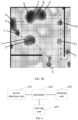
- FIG. 3A which is a schematic diagram of a scene map for a target scene
- the target scene in the scene map is divided into 8 areas, which are denoted as "area 1", “area 2", “area 3", “area 4", “area 5", “area 6", “area 7” and “area 8" respectively.
- the grids may be respectively denoted by 1, integers between 1 and n 1 , and n 1 .
- n 1 may represent the total number of grids included in the "area 1".
- the scene map may further include the target dirtiness factor for each of the grids in each of the areas.
- the target dirtiness factors may be directly shown by numerical values or by colors.
- FIG. 3C which is a schematic diagram of the target dirtiness factors for the grids in the "area 1" shown in FIG. 3B
- the target dirtiness factors for the grids in the "area 1" may be denoted by numerical values.
- FIG. 3D which is another schematic diagram of the scene map for the target scene shown in FIG. 3A
- the target dirtiness factor for each of the grids in each of the areas in the target scene is shown by colors in FIG. 3D , wherein the darker a color in the diagram is, the higher the target dirtiness factor for the location of the color is, i.e. the dirtier this location is.
- the scene map may be a map that is obtained by reducing the target scene according to a preset ratio, the target scene represented by the scene map is divided into a plurality of areas in advance, and each of the areas of the target scene represented by the scene map is divided into a plurality of grids in advance. That is, all the areas in the target scene can be represented in the scene map in a preset reduced scale, and all the grids of each of the areas of the target scene can be represented in a preset reduced scale.
- the cleaning robot may determine, based on the scene map, the grid where the cleaning robot is located in the target scene, and use this grid as a starting grid in the embodiment of the present application.
- the cleaning robot may determine, based on the scene map, the grid where the charging base is located in the target scene, and use this grid as an ending grid in the embodiment of the present application.
- the cleaning robot may determine, based on the scene map, a path along which the cleaning robot moves from the starting grid to the target cleaning area and then through all the grids in the target cleaning area and to the ending grid, and in the embodiment of the present application use this path as the first cleaning path.
- the path along which the cleaning robot moves from the starting grid to the target cleaning area may be the shortest path from the starting grid to the target cleaning area.
- the path along which the cleaning robot moves to the ending grid after traveling through all the grids in the target cleaning area may be the shortest path of the cleaning robot moving to the ending grid after traveling through all the grids in the target cleaning area.
- the cleaning robot may move based on a preset -shape rule when traveling through all the grids in the target cleaning area, so as to non-repetitively pass through all the grids in the target cleaning area. As shown in FIG.
- FIG. 3E which is a schematic diagram of the cleaning robot traveling through all the grids in the target cleaning area, the cleaning robot moves based on the preset -shape rule shown in FIG. 3E , and the starting grid may be represented at the "A" location shown in FIG. 3E , and the ending grid may be represented at the "B" location shown in FIG. 3E .
- the cleaning robot may perform the cleaning by adopting different cleaning modes with different power consumption modes.
- the cleaning robot may adopt different cleaning modes to clean the target scene based on the grids in each of the areas in the target scene in the scene map, the current power, and the target dirtiness factor for each of the grids in the target cleaning area.
- the power consumed by the cleaning robot during the cleaning process may be divided into three types: 1. the power consumed by the moving unit, such as a walking motor, of the cleaning robot during the movement of the cleaning robot; 2. the power consumed by a cleaning unit, such as a fan or rolling brush, of the cleaning robot during the cleaning of grids; 3. the power consumed by a cleaning unit, such as an side brush, of the cleaning robot during the cleaning of the grids.
- the moving unit such as a walking motor
- a cleaning unit such as a fan or rolling brush
- a cleaning unit such as an side brush
- the power required to be consumed by the cleaning robot in the process of moving along the first cleaning path and cleaning all the grids in the target cleaning area can be estimated, and then whether the power required to be consumed is less than or equal to the current power is determined. If it is determined that the power required to be consumed is less than or equal to the current power, it can be indicated that the current power of the cleaning robot can support it to clean all the grids in the target cleaning area. If it is determined that the power required to be consumed is greater than the current power, it can be indicated that the current power of the cleaning robot cannot support it to clean all the grids in the target cleaning area.
- the cleaning robot can move along the first path and clean all the grids in the target cleaning area.
- W i represents the first power consumption
- l 1 represents the length of the first cleaning path
- v represents the walking speed of the cleaning robot among grids by means of the walking motor
- w 3 represents the current of the walking motor during operation
- w 3 l 1 ⁇ represents the power consumption of the walking motor when the cleaning robot travels along the first cleaning path
- q ij represents the target dirtiness factor for the grid j in the target cleaning area i
- the value range of j is [1, n i ]
- n i represents the total number of the grids in the target cleaning area i
- w i represents the current of the side brush of the cleaning robot during operation
- ⁇ j 1 n i w 1
- q ij ⁇ 1 represents the power consumption of the side brush of the cleaning robot during operation
- ⁇ j 1 n i ⁇ 2
- q ij 2 represents the power consumption of the fan or the rolling brush during operation
- ⁇ , ⁇ 1 and ⁇ 2 are
- the current is w 2 .
- w 2 is in direct proportion to the target dirtiness factor for the grid, and the proportional relationship may be denoted as a . That is, when cleaning the grid, the larger the target dirtiness factor for the grid is, the larger the current required by the fan or the rolling brush of the cleaning robot is.
- the time required by the fan or rolling brush of the cleaning robot to finish cleaning one grid is in direct proportion to the target dirtiness factor for the grid, and the proportional relationship may be denoted as ⁇ 2 . That is, when cleaning the grid, the larger the target dirtiness factor for the grid is, the longer the time required by the fan or the rolling brush of the cleaning robot to clean is. That is, when cleaning the grid, the higher the target dirtiness factor for the grid is, the greater the power consumption of the fan or the roll brush of the cleaning robot is.
- the fan or the rolling brush and the side brush need to cooperate with each other when the cleaning robot cleans the grid, and the time required by the fan or the rolling brush to work on one grid may be the same as the time required by the side brush to work on this grid, and thus ⁇ 1 may be equal to ⁇ 2 .
- the method may further include: returning to perform the step of acquiring the current power of the cleaning robot.
- the cleaning robot determines to clean all the grids in the target cleaning area, it can be indicated that its current power is sufficient to clean all the grids in the target cleaning area. After the cleaning robot finishes cleaning all the grids in the determined target cleaning area, the remaining power of the cleaning robot may be sufficient to clean other areas to be cleaned. In this case, the cleaning robot may return to perform the step of acquiring the current power of the cleaning robot and perform the subsequent cleaning process, rather than move to the location of the charging base.
- the calculated first power consumption may be greater than the current power, it can be indicated that the current power of the cleaning robot is insufficient to clean the entire target cleaning area. That is, it is indicated that the current power of the cleaning robot is insufficient to clean all the grids in the target cleaning area.
- the cleaning method provided in the embodiment of the present application may further include: S401: if it is determined that the first power consumption is greater than the current power, determining whether there is a grid meeting a preset grid cleaning rule in the target cleaning area, based on the grids in each of the areas in the target scene in the scene map, the current power and the target dirtiness factor for each of the grids in the target cleaning area.
- the preset grid cleaning rule may be a rule that defines the sum of the target dirtiness factors for the grids determined to be cleaned from the target cleaning area to be maximum if the current power allows.
- S403 cleaning the target cleaning area based on the determined target cleaning grid, the starting grid and the ending grid.
- the cleaning path may be re-planned based on the preset grid cleaning rule. If the current power allows, the cleaning robot can clean a set of grids with the maximum sum of the target dirtiness factors for the grids in the target cleaning area. Wherein, this set of grids may include one or more grids in the target cleaning area.
- the cleaning robot may determine the shortest path that passes through each grid meeting the preset grid cleaning rule from the starting grid as a starting point to the ending grid as an ending point based on the grids in each of the areas of the target scene in the scene map, and control the cleaning unit and the moving unit to clean the target cleaning area based on the determined shortest path.
- the step of determining whether there is a grid meeting a preset grid cleaning rule in the target cleaning area, based on the grids in each of the areas in the target scene in the scene map, the current power and the target dirtiness factor for each of the grids in the target cleaning area may include:
- the preset target function has a solution under the preset constraint condition, it can be indicated that there is a grid meeting the preset grid cleaning rule in the target cleaning area, and the grid corresponding to this solution determined under the preset constraint condition is a grid meeting the preset grid cleaning rule in the target cleaning area.
- q ij k represents the target dirtiness factors for the grids determined to be cleaned from the target cleaning area, which represents that q ij k represents target dirtiness factor for each of the grids determined to be cleaned from the target cleaning area.
- the shortest path from the starting grid to the ending grid through the grids meeting the preset grid cleaning rule may be pre-estimated and determined by means of a dynamic programming method, based on the grids in each of the areas of the target scene in the scene map.
- FIG. 5A which is a schematic diagram of the cleaning robot traveling through the grids meeting the preset grid cleaning rule in the target cleaning area
- the location "C” shown in FIG. 5A may represent the starting grid
- the location "D” shown in FIG. 5A may represent the ending grid
- the locations "a", "b", “c", “d", "e” and “f” shown in FIG. 5A represent the determined grids meeting the preset grid cleaning rule, respectively.
- FIG. 5A which is a schematic diagram of the cleaning robot traveling through the grids meeting the preset grid cleaning rule in the target cleaning area
- the location “E” shown in FIG. 5B may represent the starting grid
- the location “F” shown in FIG. 5B may represent the ending grid
- locations "1", “2", “3”, “4", "5", “6", “7”, “8”, “9", "10” and “11” shown in FIG. 5B represent the determined grids meeting the preset grid cleaning rule, respectively.
- the locations "a”, “b”, “c”, “d”, “e” and “f” as shown in FIG. 5A represent the determined grids meeting the preset grid cleaning rule, respectively.
- K may be equal to 6.
- the current is w 2 .
- w 2 is in direct proportion to the target dirtiness factor for the grid, and the proportional relationship may be denoted as a . That is, when cleaning the grid, the larger the target dirtiness factor for the grid is, the larger the current required by the fan or the rolling brush of the cleaning robot is.
- the time required by the fan or rolling brush of the cleaning robot to finish cleaning one grid is in direct proportion to the target dirtiness factor for the grid, and the proportional relationship may be denoted as ⁇ 2 . That is, when cleaning the grid, the larger the target dirtiness factor for the grid is, the longer the time required by the fan or the rolling brush of the cleaning robot to clean is. That is, when cleaning the grid, the higher the target dirtiness factor for the grid is, the greater the power consumption of the fan or the roll brush of the cleaning robot is.
- the time required by the side brush of the cleaning robot in operation (i.e., when the cleaning robot is cleaning a grid, such as the jth grid in the target cleaning area i , with the side brush) is in direct proportion to the target dirtiness factor for the grid, and the proportional relationship may be denoted as ⁇ 1 . That is, when cleaning the grid, the larger the target dirtiness factor for the grid is, the longer the time required by the side brush of the cleaning robot to clean is. When the current of the side brush during operation remains unchanged, the larger the target dirtiness factor for the grid is, the greater the power consumption of the side brush of the cleaning robot is.
- the fan or the rolling brush and the side brush need to cooperate with each other when the cleaning robot cleans the grid, and the time required by the fan or the rolling brush to work on one grid may be the same as the time required by the side brush to work on this grid, and thus ⁇ 1 may be equal to ⁇ 2.
- the target cleaning area after finishing cleaning the target cleaning area, may be identified based on the scene map, to distinguish it from the areas to be cleaned. In one case, after finishing cleaning the target cleaning area, the target cleaning area may be set based on the scene map, so as to change its state from a non-set state to a set state. If the cleaning robot fails to acquire a cleaning instruction for the target scene within a predetermined time threshold, all of the set areas may be modified into the non-set state based on the scene map.
- the step of cleaning the target cleaning area based on the determined target cleaning grid, the starting grid and the ending grid may include: cleaning the target cleaning area according to the second cleaning path.
- the fan or the rolling brush and the side brush can be turned off during the process of the cleaning robot walking among the grids according to the second cleaning path, so as to save the power. Only when the cleaning robot moves to the target cleaning grid, the fan or the rolling brush and the side brush may be turned on to clean the target cleaning grid.
- the cleaning robot may directly move to the location of the charging base for charging after cleaning the target cleaning area according to the second cleaning path.
- the method may further include:
- the grid may be a grid of a predetermined size.
- the cleaning robot may detect the amount of dust for the grid in the target cleaning area by a dust detection unit in real time, when cleaning the grid in the target cleaning area.
- the cleaning robot may detect the grid for a plurality of times by the dust detection unit, thus generating a plurality of detection results, wherein one detection result is generated during one detection process.
- the first historical dirtiness factor for the grid may be determined based on the generated detection results, wherein, either the sum or the average of the plurality of detection results may be used as the first historical dirtiness factor for the grid, which are both feasible.
- the preset number may be a value set autonomously by the user, or may be a value set by the cleaning robot as a default, which are both feasible.
- the preset number may be denoted as t
- the first historical dirtiness factor may be denoted as d 0
- the dirtiness factors recorded in the previous t times of cleanings i.e. the second historical dirtiness factors, may be denoted as d 1 -d t , respectively.
- updating the target dirtiness factor for the grid based on the first historical dirtiness factor d 0 and the second historical dirtiness factors d 1 -d t for the grid may include: calculating the average value of the first historical dirtiness factor d 0 and the second historical dirtiness factors d 1 -d t , and updating the calculated average value as the target dirtiness factor for the grid.
- the cleaning robot may calculate parameters of the Gaussian distribution based on d 0 and d 1 -dt , wherein the distribution mean value in the parameters of the Gaussian distribution may be updated as the target dirtiness factor for the grid, wherein the distribution mean value may be denoted as d mean .
- an embodiment of the present application further provides a cleaning robot, as shown in FIG. 6 .
- the cleaning robot may include:
- the cleaning robot may determine the target cleaning area to be cleaned based on target dirtiness levels for all areas to be cleaned in the target scene, such that the cleaning robot is more intelligent when determining the target cleaning area and thus the target cleaning area determined thereby is more reasonable. Further, the cleaning robot may clean the target cleaning area based on the scene map for the target scene, the current power and the target dirtiness level for the target cleaning area, such that the cleaning robot is more intelligent and the cleaning process of the cleaning robot is more reasonable.
- the processor 620 is specifically configured for determining an area to be cleaned having a maximum target dirtiness level from all the areas to be cleaned in the target scene as the target cleaning area, based on the target dirtiness level for each of the areas to be cleaned.
- the processor 620 is specifically configured for determining an area to be cleaned having a minimum target dirtiness level from all the areas to be cleaned in the target scene as the target cleaning area, based on the target dirtiness level for each of the areas to be cleaned.
- all areas in the target scene are represented in the scene map in a preset reduced scale, and each of the areas in the target scene represented in the scene map is divided into a plurality of grids in advance;
- the cleaning unit includes a fan or a rolling brush and a side brush
- the moving unit includes a walking motor
- the processor 620 is further configured for: after cleaning all the grids in the target cleaning area, based on the grids in each of the areas in the target scene in the scene map, the first cleaning path and the target dirtiness factors for all the grids in the target cleaning area, returning to acquire the current power of the cleaning robot.
- the processor 620 is further configured for:
- the cleaning unit includes a fan or a rolling brush and a side brush, and the moving unit includes a walking motor; the processor 620 is specifically configured for:
- the processor 620 is specifically configured for: controlling the cleaning unit and the moving unit to clean the target cleaning area according to the second cleaning path.
- the processor 620 is further configured for:
- the above cleaning robot may further include a dust detection unit.
- the cleaning robot may detect and store the amount of dust for a grid in the target cleaning area, when cleaning the grid in the target cleaning area, with the dust detection unit in real time. wherein when the area of the grid is large, for example, larger than a preset area threshold, the cleaning robot may detect the grid for a plurality of times by the dust detection unit, thus generating a plurality of detection results. Wherein one detection result is generated during one detection process, and thereby determining the amount of dust for the grid based on the plurality of detection results for each of the grids, for instance, taking the sum or the average of the plurality of detection results as the amount of dust for this grid.
- the processor of the cleaning robot may determine a dirtiness factor for each of the grids during one cleaning process by acquiring the amount of dust for each of the grids detected by the dust detection unit. Subsequently, the processor of the cleaning robot may update the target dirtiness factor for each of the grids based on the determined dirtiness factor for each of the grids during each cleaning process.
- the step of the processor of the cleaning robot determining a dirtiness factor for each of the grids during one cleaning process by acquiring the amount of dust for each of the grids detected by the dust detection unit may be: determining the amount of dust for each of the grids as the dirtiness factor for the grid during one cleaning process; or determining the dirtiness factor for each of the grids during one cleaning process by acquiring the amount of dust for each of the grids detected by the dust detection unit, based on a direct proportion relationship; or, determining the dirtiness factor for each of the grids during one cleaning process by acquiring the amount of dust for each of the grids detected by the dust detection unit, based on an inverse proportion relationship.
- the foregoing processor may be a general-purpose processor, including a Central Processing Unit (CPU), a Network Processor (NP), and the like; or a Digital Signal Processing (DSP), an Application Specific Integrated Circuit (ASIC), a Field-Programmable Gate Array (FPGA) or other programmable logic devices, discrete gate or transistor logic devices, discrete hardware components.
- CPU Central Processing Unit
- NP Network Processor
- DSP Digital Signal Processing
- ASIC Application Specific Integrated Circuit
- FPGA Field-Programmable Gate Array
- an embodiment of the present application provides a computer-readable storage medium, in which a computer program is stored.
- the computer program when executed by a processor, performs any one of the cleaning methods provided by the embodiments of the present application.
- the cleaning method may include:
- the cleaning robot may determine the target cleaning area to be cleaned based on target dirtiness levels for all areas to be cleaned in the target scene, such that the cleaning robot is more intelligent when determining the target cleaning area and thus the target cleaning area determined thereby is more reasonable. Further, the cleaning robot may clean the target cleaning area based on the scene map for the target scene, the current power and the target dirtiness level for the target cleaning area, such that the cleaning robot is more intelligent and the cleaning process of the cleaning robot is more reasonable.
- determining a target cleaning area from all the areas to be cleaned in the target scene, based on a target dirtiness level for each of the areas to be cleaned includes: determining an area to be cleaned having a maximum target dirtiness level from all the areas to be cleaned in the target scene as the target cleaning area, based on the target dirtiness level for each of the areas to be cleaned.
- determining a target cleaning area from all the areas to be cleaned in the target scene, based on a target dirtiness level for each of the areas to be cleaned includes: determining an area to be cleaned having a minimum target dirtiness level from all the areas to be cleaned in the target scene as the target cleaning area, based on the target dirtiness level for each of the areas to be cleaned.
- all areas in the target scene are represented in the scene map in a preset reduced scale, and each of the areas in the target scene represented in the scene map is divided into a plurality of grids in advance,
- the method further includes: returning to acquire the current power of the cleaning robot.
- the method further includes:
- the step of determining whether there is a grid meeting a preset grid cleaning rule in the target cleaning area, based on the grids in each of the areas in the target scene in the scene map, the current power and the target dirtiness factor for each of the grids in the target cleaning area includes:
- the step of cleaning the target cleaning area based on the determined target cleaning grid, the starting grid and the ending grid includes: cleaning the target cleaning area according to the second cleaning path.
- the method further includes:
- an embodiment of the present application provides a computer program product that, when executed by a computer, causes the computer to perform the cleaning method of any one of the above embodiments.
- the cleaning robot may determine the target cleaning area to be cleaned based on target dirtiness levels for all areas to be cleaned in the target scene, such that the cleaning robot is more intelligent when determining the target cleaning area and thus the target cleaning area determined thereby is more reasonable. Further, the cleaning robot may clean the target cleaning area based on the scene map for the target scene, the current power and the target dirtiness level for the target cleaning area, such that the cleaning robot is more intelligent and the cleaning process of the cleaning robot is more reasonable.
Landscapes
- Engineering & Computer Science (AREA)
- Mechanical Engineering (AREA)
- Aviation & Aerospace Engineering (AREA)
- Radar, Positioning & Navigation (AREA)
- Remote Sensing (AREA)
- Physics & Mathematics (AREA)
- General Physics & Mathematics (AREA)
- Automation & Control Theory (AREA)
- Electric Vacuum Cleaner (AREA)
- Control Of Position, Course, Altitude, Or Attitude Of Moving Bodies (AREA)
Claims (15)
- Procédé de nettoyage, comprenant :après qu'un robot de nettoyage a obtenu une instruction de nettoyage pour une scène cible, l'acquisition d'une carte de scène pour la scène cible et l'acquisition d'une puissance actuelle du robot de nettoyage (5101) ;s'il est déterminé que la puissance actuelle est insuffisante pour nettoyer toutes les zones à nettoyer dans la scène cible, la détermination d'une zone de nettoyage cible parmi toutes les zones à nettoyer dans la scène cible, sur la base d'un niveau de saleté cible pour chacune des zones à nettoyer (S102) ;le nettoyage de la zone de nettoyage cible sur la base de la carte de scène, du niveau de saleté cible pour la zone de nettoyage cible et de la puissance actuelle (S103) ;dans lequel toutes les zones dans la scène cible sont représentées dans la carte de scène à une échelle réduite prédéfinie, et chacune des zones dans la scène cible représentées dans la carte de scène est divisée en une pluralité de grilles à l'avance ;dans lequel, le facteur de saleté cible est un facteur déterminé sur la base de facteurs de saleté historiques pour la grille correspondante et est en proportion directe avec une situation de saleté de la grille correspondante, et le niveau de saleté cible pour la zone de nettoyage cible est une somme ou une moyenne de facteurs de saleté cibles pour toutes les grilles dans la zone de nettoyage cible ;dans lequel l'étape de nettoyage de la zone de nettoyage cible sur la base de la carte de scène, du niveau de saleté cible pour la zone de nettoyage cible et de la puissance actuelle (S103) comprend :la détermination d'une grille où le robot de nettoyage est situé dans la scène cible comme grille de départ et la détermination d'une grille où une base de chargement est située dans la scène cible comme grille de fin, sur la base des grilles dans chacune des zones dans la scène cible dans la carte de scène (S201) ;la détermination d'un parcours de la grille de départ vers la grille de fin via toutes les grilles dans la zone de nettoyage cible comme premier parcours de nettoyage, sur la base des grilles dans chacune des zones dans la scène cible dans la carte de scène (S202) ;la détermination d'une consommation de puissance pendant un processus du robot de nettoyage finissant de nettoyer toutes les grilles dans la zone de nettoyage cible comme première consommation de puissance, sur la base du premier parcours de nettoyage et des facteurs de saleté cible pour toutes les grilles dans la zone de nettoyage cible (S203) ;la détermination si la première consommation de puissance est supérieure à la puissance actuelle (S204) ;s'il est déterminé que la première consommation de puissance n'est pas supérieure à la puissance actuelle, le nettoyage de toutes les grilles dans la zone de nettoyage cible sur la base des grilles dans chacune des zones dans la scène cible dans la carte de scène, du premier parcours de nettoyage et des facteurs de saleté cible pour toutes les grilles dans la zone de nettoyage cible (S205).
- Procédé selon la revendication 1, dans lequel l'étape de détermination d'une zone de nettoyage cible parmi toutes les zones à nettoyer dans la scène cible, sur la base d'un niveau de saleté cible pour chacune des zones à nettoyer (S102) comprend :
la détermination d'une zone à nettoyer ayant un niveau de saleté cible maximum ou minimum parmi toutes les zones à nettoyer dans la scène cible comme étant la zone de nettoyage cible, sur la base du niveau de saleté cible pour chacune des zones à nettoyer. - Procédé selon l'une quelconque des revendications 1 à 2, dans lequel le procédé comprend en outre, après l'étape de nettoyage de toutes les grilles dans la zone de nettoyage cible (S205) :l'obtention, par des statistiques, et l'enregistrement d'un facteur de saleté pour chacune des grilles dans la zone de nettoyage cible pendant le nettoyage cette fois-ci comme premier facteur de saleté historique ;l'acquisition de facteurs de saleté enregistrés dans un nombre prédéfini de nettoyages précédents pour chacune des grilles dans la zone de nettoyage cible comme seconds facteurs de saleté historiques ;pour chacune des grilles dans la zone de nettoyage cible, la mise à jour du facteur de saleté cible pour la grille sur la base du premier facteur de saleté historique et des seconds facteurs de saleté historiques pour la grille.
- Procédé selon la revendication 3, dans lequel une formule utilisée dans l'étape de détermination d'une consommation de puissance pendant un processus du robot de nettoyage finissant de nettoyer toutes les grilles dans la zone de nettoyage cible comme première consommation de puissance, sur la base du premier parcours de nettoyage et des facteurs de saleté cible pour toutes les grilles dans la zone de nettoyage cible (S203) est :


- Procédé selon la revendication 3, dans lequel le procédé comprend en outre, après l'étape de nettoyage de toutes les grilles dans la zone de nettoyage cible, sur la base des grilles dans chacune des zones dans la scène cible dans la carte de scène, du premier parcours de nettoyage et des facteurs de saleté cible pour toutes les grilles dans la zone de nettoyage cible (S205) :
le retour à l'exécution de l'étape d'acquisition de la puissance actuelle du robot de nettoyage. - Procédé selon la revendication 3, comprenant en outre :s'il est déterminé que la première consommation de puissance est supérieure à la puissance actuelle, la détermination s'il existe une grille satisfaisant à une règle de nettoyage de grille prédéfinie dans la zone de nettoyage cible, sur la base des grilles dans chacune des zones dans la scène cible dans la carte de scène, de la puissance actuelle et du facteur de saleté cible pour chacune des grilles dans la zone de nettoyage cible (S301), dans lequel la règle de nettoyage de grille prédéfinie est une règle qui définit la somme des facteurs de saleté cible pour les grilles déterminées comme devant être nettoyées de la zone de nettoyage cible comme étant maximale si la puissance actuelle le permet ;s'il est déterminé qu'il existe une grille satisfaisant à la règle de nettoyage de grille prédéfinie, la détermination de la grille satisfaisant à la règle de nettoyage de grille prédéfinie comme grille de nettoyage cible (S302) ;le nettoyage de la zone de nettoyage cible sur la base de la grille de nettoyage cible déterminée, de la grille de départ et de la grille de fin (S303).
- Procédé selon la revendication 6, dans lequel l'étape de détermination s'il existe une grille satisfaisant à une règle de nettoyage de grille prédéfinie dans la zone de nettoyage cible, sur la base des grilles dans chacune des zones dans la scène cible dans la carte de scène, de la puissance actuelle et du facteur de saleté cible pour chacune des grilles dans la zone de nettoyage cible (S301) comprend :l'acquisition d'une fonction cible prédéfinie pour représenter une somme maximale des facteurs de saleté cible pour les grilles déterminées comme devant être nettoyées de la zone de nettoyage cible, dans lequel la fonction cible prédéfinie est :
 dans lequel, qij
k représente les facteurs de saleté cible pour les grilles déterminées comme devant être nettoyées de la zone de nettoyage cible ; une plage de valeurs de K est [1, n i ] ; n i représente le nombre total des grilles dans une zone de nettoyage cible i ;la détermination si la fonction cible prédéfinie a une solution dans une condition de contrainte prédéfinie ; s'il est déterminé que la fonction cible prédéfinie a la solution, il est représenté qu'il existe une grille satisfaisant à la règle de nettoyage de grille prédéfinie, et la grille satisfaisant à la règle de nettoyage de grille prédéfinie est une grille correspondant à la solution de la fonction cible prédéfinie ;la condition de contrainte prédéfinie est : dans lequel, W' représente la consommation de puissance pendant un processus dans lequel le robot de nettoyage se déplace de la grille de départ, termine le nettoyage de toutes les grilles déterminées comme devant être nettoyées de la zone de nettoyage cible et atteint la grille de fin, comme seconde consommation de puissance ; l2 représente une longueur d'un parcours le plus court le long duquel le robot de nettoyage se déplace de la grille de départ, termine le nettoyage de toutes les grilles déterminées comme devant être nettoyées de la zone de nettoyage cible et atteint la grille de fin, comme longueur d'un second parcours de nettoyage ; v représente une vitesse d'avance du robot de nettoyage parmi les grilles au moyen d'un moteur d'avance ; w 3 représente un courant du moteur d'avance pendant le fonctionnement ;
k représente les facteurs de saleté cible pour les grilles déterminées comme devant être nettoyées de la zone de nettoyage cible ; w 1 représente un courant d'une brosse latérale du robot de nettoyage pendant le fonctionnement ;
 dans lequel l'étape de nettoyage de la zone de nettoyage cible sur la base de la grille de nettoyage cible déterminée, de la grille de départ et de la grille de fin (S303) comprend, de préférence :
le nettoyage de la zone de nettoyage cible selon le second parcours de nettoyage. - Robot de nettoyage, comprenant :une unité de détection de puissance (610) configurée pour détecter une puissance du robot de nettoyage ;un processeur (620) configuré pour, après l'obtention d'une instruction de nettoyage pour une scène cible, acquérir une carte de scène pour la scène cible et acquérir une puissance actuelle du robot de nettoyage détectée par l'unité de détection de puissance (610) ; s'il est déterminé que la puissance actuelle est insuffisante pour nettoyer toutes les zones à nettoyer dans la scène cible, déterminer une zone de nettoyage cible parmi toutes les zones à nettoyer dans la scène cible, sur la base d'un niveau de saleté cible pour chacune des zones à nettoyer ; commander une unité de déplacement (630) pour conduire le robot de nettoyage dans la zone de nettoyage cible, et commander une unité de nettoyage (640) pour nettoyer la zone de nettoyage cible, sur la base de la carte de scène, du niveau de saleté cible pour la zone de nettoyage cible et de la puissance actuelle ;l'unité de déplacement (630) configurée pour conduire le robot de nettoyage pour qu'il se déplace ;l'unité de nettoyage (640) configurée pour nettoyer la zone de nettoyage cible ;caractérisé en ce que toutes les zones dans la scène cible sont représentées dans la carte de scène à une échelle réduite prédéfinie, et chacune des zones dans la scène cible représentées dans la carte de scène est divisée en une pluralité de grilles à l'avance ;chacune des grilles dans chacune des zones dans la scène cible correspond à un facteur de saleté cible ; dans lequel, le facteur de saleté cible est un facteur déterminé sur la base de facteurs de saleté historiques pour la grille correspondante et est en proportion directe avec une situation de saleté de la grille correspondante, et le niveau de saleté cible pour la zone de nettoyage cible est une somme ou une moyenne de facteurs de saleté cible pour toutes les grilles dans la zone de nettoyage cible ;le processeur (620) est spécifiquement configuré pour :déterminer une grille où le robot de nettoyage est situé dans la scène cible comme grille de départ et déterminer une grille où une base de chargement est située dans la scène cible comme grille de fin, sur la base des grilles dans chacune des zones dans la scène cible dans la carte de scène ;déterminer un parcours de la grille de départ vers la grille de fin via toutes les grilles dans la zone de nettoyage cible comme premier parcours de nettoyage, sur la base des grilles dans chacune des zones dans la scène cible dans la carte de scène ;déterminer la consommation de puissance pendant un processus de commande de l'unité de nettoyage (640) et de l'unité de déplacement (630) pour terminer le nettoyage de toutes les grilles dans la zone de nettoyage cible comme première consommation de puissance, sur la base du premier parcours de nettoyage et des facteurs de saleté cible pour toutes les grilles dans la zone de nettoyage cible ;déterminer si la première consommation de puissance est supérieure à la puissance actuelle ;s'il est déterminé que la première consommation de puissance n'est pas supérieure à la puissance actuelle, commander l'unité de nettoyage (640) et l'unité de déplacement (630) pour nettoyer toutes les grilles dans la zone de nettoyage cible, sur la base des grilles dans chacune des zones dans la scène cible dans la carte de scène, du premier parcours de nettoyage et des facteurs de saleté cible pour toutes les grilles dans la zone de nettoyage cible.
- Robot de nettoyage selon la revendication 8, dans lequel le processeur (620) est spécifiquement configuré pour :
déterminer une zone à nettoyer ayant un niveau de saleté cible maximum ou minimum parmi toutes les zones à nettoyer dans la scène cible comme étant la zone de nettoyage cible, sur la base du niveau de saleté cible pour chacune des zones à nettoyer. - Robot de nettoyage selon l'une quelconque des revendications 8 à 9, dans lequel
le processeur (620) est en outre configuré pour :après le nettoyage de toutes les grilles dans la zone de nettoyage cible, sur la base des grilles dans chacune des zones dans la scène cible dans la carte de scène, du premier parcours de nettoyage et des facteurs de saleté cible pour toutes les grilles dans la zone de nettoyage cible, le retour à l'acquisition de la puissance actuelle du robot de nettoyage ;dans lequel le processeur (620) est de préférence configuré en outre pour :après le nettoyage de toutes les grilles dans la zone de nettoyage cible, l'obtention, par des statistiques, et l'enregistrement d'un facteur de saleté pour chacune des grilles dans la zone de nettoyage cible pendant le nettoyage cette fois comme premier facteur de saleté historique ;l'acquisition de facteurs de saleté enregistrés dans un nombre prédéfini de nettoyages précédents pour chacune des grilles dans la zone de nettoyage cible comme seconds facteurs de saleté historiques ;pour chacune des grilles dans la zone de nettoyage cible, la mise à jour du facteur de saleté cible pour la grille sur la base du premier facteur de saleté historique et des seconds facteurs de saleté historiques pour la grille. - Robot de nettoyage selon la revendication 10, dans lequel l'unité de nettoyage (640) comprend un ventilateur ou une brosse roulante et une brosse latérale, et l'unité de déplacement (630) comprend un moteur d'avance ;une formule utilisée par le processeur (620) est :
 dans lequel, Wi représente la première consommation de puissance ; l1 représente une longueur du premier parcours de nettoyage ; v représente une vitesse d'avance du robot de nettoyage parmi les grilles au moyen du moteur d'avance ; w 3 représente un courant du moteur d'avance pendant le fonctionnement ;


- Robot de nettoyage selon la revendication 10, dans lequel le processeur (620) est en outre configuré pour :s'il est déterminé que la première consommation de puissance est supérieure à la puissance actuelle, la détermination s'il existe une grille satisfaisant à une règle de nettoyage de grille prédéfinie dans la zone de nettoyage cible, sur la base des grilles dans chacune des zones dans la scène cible dans la carte de scène, de la puissance actuelle et du facteur de saleté cible pour chacune des grilles dans la zone de nettoyage cible, dans lequel la règle de nettoyage de grille prédéfinie est une règle qui définit la somme des facteurs de saleté cible pour les grilles déterminées comme devant être nettoyées de la zone de nettoyage cible comme étant maximale si la puissance actuelle le permet ;s'il est déterminé qu'il existe une grille satisfaisant à la règle de nettoyage de grille prédéfinie, la détermination de la grille satisfaisant à la règle de nettoyage de grille prédéfinie comme grille de nettoyage cible ;commander l'unité de nettoyage (640) et l'unité de déplacement (630) pour nettoyer la zone de nettoyage cible sur la base de la grille de nettoyage cible déterminée, de la grille de départ et de la grille de fin.
- Robot de nettoyage selon la revendication 12, dans lequel l'unité de nettoyage (640) comprend un ventilateur ou une brosse roulante et une brosse latérale, et l'unité de déplacement (630) comprend un moteur d'avance ;
dans lequel le processeur (620) est spécifiquement configuré pour :acquérir une fonction cible prédéfinie pour représenter une somme maximale des facteurs de saleté cible pour les grilles déterminées comme devant être nettoyées de la zone de nettoyage cible, dans lequel la fonction cible prédéfinie est : dans lequel, qij
k représente les facteurs de saleté cible pour les grilles déterminées comme devant être nettoyées de la zone de nettoyage cible ; une plage de valeurs de K est [1, ni ] ; n i représente le nombre total des grilles dans une zone de nettoyage cible i ;la détermination si la fonction cible prédéfinie a une solution dans une condition de contrainte prédéfinie ; s'il est déterminé que la fonction cible prédéfinie a la solution, il est représenté qu'il existe une grille satisfaisant à la règle de nettoyage de grille prédéfinie, et la grille satisfaisant à la règle de nettoyage de grille prédéfinie est une grille correspondant à la solution de la fonction cible prédéfinie ;la condition de contrainte prédéfinie est : dans lequel, W' représente la consommation de puissance pendant un processus dans lequel le robot de nettoyage commande l'unité de nettoyage (640) et l'unité de déplacement (630) pour se déplacer de la grille de départ, terminer le nettoyage de toutes les grilles déterminées comme devant être nettoyées de la zone de nettoyage cible et atteindre la grille de fin, comme seconde consommation de puissance ; l2 représente une longueur d'un parcours le plus court le long duquel le robot de nettoyage se déplace de la grille de départ, termine le nettoyage de toutes les grilles déterminées comme devant être nettoyées de la zone de nettoyage cible et atteint la grille de fin, comme longueur d'un second parcours de nettoyage ; v représente une vitesse d'avance du robot de nettoyage parmi les grilles au moyen du moteur d'avance ; w 3 représente un courant du moteur d'avance pendant le fonctionnement ;
k représente les facteurs de saleté cible pour les grilles déterminées comme devant être nettoyées de la zone de nettoyage cible ; w 1 représente un courant de la brosse latérale du robot de nettoyage pendant le fonctionnement ;
 dans lequel le processeur (620) est de préférence configuré spécifiquement pour commander l'unité de nettoyage (640) et l'unité de déplacement (630) pour nettoyer la zone de nettoyage cible selon le second parcours de nettoyage.
 - Support de stockage lisible par ordinateur, dans lequel un programme informatique est stocké, dans lequel le programme informatique, lorsqu'il est exécuté par un processeur (620), exécute des étapes du procédé de nettoyage selon l'une quelconque des revendications 1 à 7.
- Produit de programme informatique qui, lorsqu'il est exécuté par un ordinateur, amène l'ordinateur à exécuter des étapes du procédé de nettoyage selon l'une quelconque des revendications 1 à 7.
Applications Claiming Priority (2)
| Application Number | Priority Date | Filing Date | Title |
|---|---|---|---|
| CN201711434377.8A CN109953700B (zh) | 2017-12-26 | 2017-12-26 | 一种清扫方法及清洁机器人 |
| PCT/CN2018/119035 WO2019128636A1 (fr) | 2017-12-26 | 2018-12-04 | Procédé de nettoyage et robot de nettoyage |
Publications (3)
| Publication Number | Publication Date |
|---|---|
| EP3733038A1 EP3733038A1 (fr) | 2020-11-04 |
| EP3733038A4 EP3733038A4 (fr) | 2021-01-20 |
| EP3733038B1 true EP3733038B1 (fr) | 2023-10-04 |
Family
ID=67022333
Family Applications (1)
| Application Number | Title | Priority Date | Filing Date |
|---|---|---|---|
| EP18896191.6A Active EP3733038B1 (fr) | 2017-12-26 | 2018-12-04 | Procédé de nettoyage et robot de nettoyage |
Country Status (6)
| Country | Link |
|---|---|
| US (1) | US11589722B2 (fr) |
| EP (1) | EP3733038B1 (fr) |
| CN (1) | CN109953700B (fr) |
| ES (1) | ES2966587T3 (fr) |
| PL (1) | PL3733038T3 (fr) |
| WO (1) | WO2019128636A1 (fr) |
Families Citing this family (20)
| Publication number | Priority date | Publication date | Assignee | Title |
|---|---|---|---|---|
| KR102317048B1 (ko) | 2019-08-23 | 2021-10-25 | 엘지전자 주식회사 | 로봇 청소기 및 이의 제어방법 |
| CN110712204B (zh) * | 2019-09-27 | 2021-07-23 | 深圳乐动机器人有限公司 | 一种机器人工作的方法及机器人 |
| KR20210096493A (ko) * | 2020-01-28 | 2021-08-05 | 엘지전자 주식회사 | 인공지능형 로봇 디바이스를 제어하는 방법 |
| CN111486846B (zh) * | 2020-04-27 | 2021-12-31 | 小狗电器互联网科技(北京)股份有限公司 | 扫地机器人对优先区域进行清扫的方法 |
| CN113616836B (zh) * | 2020-05-09 | 2024-07-02 | 青岛海尔科技有限公司 | 杀菌方法、系统、终端和可读存储介质 |
| CN111950431B (zh) * | 2020-08-07 | 2024-03-26 | 北京猎户星空科技有限公司 | 一种对象查找方法及装置 |
| CN112515577B (zh) | 2020-09-30 | 2022-08-09 | 深圳银星智能集团股份有限公司 | 清洁机器人的自清洁方法、清洁机器人及清洁系统 |
| CN112386171B (zh) * | 2020-11-18 | 2021-11-05 | 福州市长乐区三互信息科技有限公司 | 楼宇物业智能清洁方法及其系统 |
| CN112971645B (zh) * | 2021-02-07 | 2022-03-08 | 美智纵横科技有限责任公司 | 一种清洁方法、装置和计算机存储介质 |
| CN113040668B (zh) * | 2021-03-03 | 2022-06-03 | 深圳市无限动力发展有限公司 | 自动更新拖布的方法、装置和计算机设备 |
| CN113303703A (zh) * | 2021-04-28 | 2021-08-27 | 深圳乐动机器人有限公司 | 一种清洁机器人的控制方法、清洁机器人及存储介质 |
| CN113520233B (zh) * | 2021-09-16 | 2023-04-07 | 深圳市元鼎智能创新有限公司 | 多打扫模式的扫地机器人的控制方法、装置及扫地机器人 |
| CN113876250B (zh) * | 2021-09-30 | 2022-12-20 | 杭州华橙软件技术有限公司 | 设备的控制方法、装置、存储介质及电子装置 |
| CN116098518A (zh) * | 2021-11-09 | 2023-05-12 | 美智纵横科技有限责任公司 | 清洁机器人的控制方法、装置、清洁机器人及存储介质 |
| GB2616658A (en) * | 2022-03-17 | 2023-09-20 | Dyson Technology Ltd | Control of a robotic vacuum cleaner based on dust distribution data |
| CN114983272B (zh) * | 2022-05-30 | 2024-05-14 | 美智纵横科技有限责任公司 | 场景地图处理方法和装置、清洁组件和清洁设备 |
| CN115429160B (zh) * | 2022-07-27 | 2023-07-14 | 云鲸智能(深圳)有限公司 | 清洁机器人的控制方法、装置、系统及存储介质 |
| CN115444310B (zh) * | 2022-08-24 | 2023-08-04 | 海宁市霖灏智能家居有限公司 | 一种基于智能沙发用表面清理装置 |
| CN115363492B (zh) * | 2022-09-23 | 2023-07-21 | 珠海格力电器股份有限公司 | 识别污水箱水满误触发的方法、装置、清洁设备及介质 |
| CN117481546B (zh) * | 2024-01-03 | 2024-03-29 | 深圳安培时代数字能源科技有限公司 | 窗户清洁方法及相关装置 |
Family Cites Families (16)
| Publication number | Priority date | Publication date | Assignee | Title |
|---|---|---|---|---|
| US7805220B2 (en) | 2003-03-14 | 2010-09-28 | Sharper Image Acquisition Llc | Robot vacuum with internal mapping system |
| KR100791382B1 (ko) | 2006-06-01 | 2008-01-07 | 삼성전자주식회사 | 로봇의 이동 경로에 따라 소정 영역의 특성에 관한 정보를수집하고 분류하는 방법 및 상기 영역 특성에 따라제어되는 로봇, 상기 영역 특성을 이용한 ui 구성 방법및 장치 |
| US8838268B2 (en) | 2008-01-28 | 2014-09-16 | Seegrid Corporation | Service robot and method of operating same |
| TW201239643A (en) * | 2011-03-30 | 2012-10-01 | Micro Star Int Co Ltd | Clean path guiding method with dirt detection |
| KR101984214B1 (ko) * | 2012-02-09 | 2019-05-30 | 삼성전자주식회사 | 로봇 청소기의 청소 작업을 제어하기 위한 장치 및 방법 |
| US8972061B2 (en) * | 2012-11-02 | 2015-03-03 | Irobot Corporation | Autonomous coverage robot |
| AU2015224421B2 (en) * | 2012-11-02 | 2017-04-06 | Irobot Corporation | Autonomous coverage robot |
| US9233472B2 (en) * | 2013-01-18 | 2016-01-12 | Irobot Corporation | Mobile robot providing environmental mapping for household environmental control |
| WO2014113091A1 (fr) | 2013-01-18 | 2014-07-24 | Irobot Corporation | Systèmes de gestion environnementale comprenant des robots mobiles et procédés les utilisant |
| JP2014161448A (ja) * | 2013-02-22 | 2014-09-08 | Toshiba Corp | 電気掃除機 |
| KR102116285B1 (ko) * | 2013-11-29 | 2020-06-05 | 삼성전자주식회사 | 청소 로봇 및 그 제어 방법 |
| CN106913289B (zh) * | 2015-12-25 | 2021-01-01 | 北京奇虎科技有限公司 | 扫地机器人的清扫处理方法和装置 |
| CN105790372A (zh) | 2016-04-22 | 2016-07-20 | 国网天津市电力公司 | 一种全自动巡视清扫机器人自动充电系统 |
| CN105892321B (zh) | 2016-04-28 | 2018-11-23 | 京东方科技集团股份有限公司 | 一种清洁机器人的调度方法及调度装置 |
| CN106983454B (zh) * | 2017-05-12 | 2020-11-20 | 北京小米移动软件有限公司 | 扫地机器人清扫方法及扫地机器人 |
| CN107328419A (zh) * | 2017-06-21 | 2017-11-07 | 上海斐讯数据通信技术有限公司 | 一种清扫机器人的清扫路径的规划方法及清扫机器人 |
-
2017
- 2017-12-26 CN CN201711434377.8A patent/CN109953700B/zh active Active
-
2018
- 2018-12-04 EP EP18896191.6A patent/EP3733038B1/fr active Active
- 2018-12-04 PL PL18896191.6T patent/PL3733038T3/pl unknown
- 2018-12-04 ES ES18896191T patent/ES2966587T3/es active Active
- 2018-12-04 WO PCT/CN2018/119035 patent/WO2019128636A1/fr unknown
- 2018-12-04 US US16/957,167 patent/US11589722B2/en active Active
Also Published As
| Publication number | Publication date |
|---|---|
| EP3733038A1 (fr) | 2020-11-04 |
| PL3733038T3 (pl) | 2024-03-18 |
| US20200345192A1 (en) | 2020-11-05 |
| EP3733038A4 (fr) | 2021-01-20 |
| US11589722B2 (en) | 2023-02-28 |
| CN109953700B (zh) | 2020-09-25 |
| ES2966587T3 (es) | 2024-04-23 |
| WO2019128636A1 (fr) | 2019-07-04 |
| CN109953700A (zh) | 2019-07-02 |
Similar Documents
| Publication | Publication Date | Title |
|---|---|---|
| EP3733038B1 (fr) | Procédé de nettoyage et robot de nettoyage | |
| JP2020518906A (ja) | ロボットのナビゲーションの方法 | |
| JP6430944B2 (ja) | 床面を自律式に点検または処理するロボットおよび方法 | |
| CN108209750B (zh) | 扫地机的清扫方法、扫地机和计算机可读存储介质 | |
| CN108606728B (zh) | 一种扫地机器人控制方法、设备、扫地机器人及存储介质 | |
| US11878425B1 (en) | Robot task optimization based on historical task and location correlated durations | |
| EP3264212B1 (fr) | Système et procédé permettant de déterminer un trajet économe en énergie d'un dispositif autonome | |
| CN112650205B (zh) | 一种清洁监控方法、清洁设备、服务器及存储介质 | |
| US20170371341A1 (en) | Method and apparatus for controlling a robotic cleaning device for intensive cleaning | |
| CN110088704A (zh) | 控制清洁设备的方法 | |
| CN108209743B (zh) | 一种定点清洁方法、装置、计算机设备和存储介质 | |
| CN108803586B (zh) | 一种扫地机器人的工作方法 | |
| CN106843239A (zh) | 基于地图预测的机器人运动控制方法 | |
| EP3834692A1 (fr) | Appareil de nettoyage robotisé et procédé de commande associé | |
| CN112741562A (zh) | 扫地机控制方法、装置、设备及计算机可读存储介质 | |
| Amigoni et al. | How much worth is coordination of mobile robots for exploration in search and rescue? | |
| CN114557633B (zh) | 自动清洁设备清洁参数配置方法、装置、设备及介质 | |
| WO2024146381A1 (fr) | Procédé de traitement de carte, appareil de traitement de carte, support et dispositif électronique | |
| CN115137251B (zh) | 扫地机器人及其控制方法、控制系统及存储介质 | |
| WO2024087793A1 (fr) | Procédé et appareil de nettoyage pour robot de nettoyage, et support et dispositif électronique | |
| TW202429391A (zh) | 地圖處理方法、地圖處理裝置、介質及電子設備 | |
| CN118490117A (zh) | 多区域的清洁方法、清洁装置、清洁设备和存储介质 | |
| CN114626696A (zh) | 清扫车调度方法、装置、计算机设备和存储介质 | |
| CN118415543A (zh) | 一种清洁设备的控制方法、装置、电子设备及存储介质 | |
| CN117032253A (zh) | 机器人的控制方法、机器人和清洁系统 |
Legal Events
| Date | Code | Title | Description |
|---|---|---|---|
| STAA | Information on the status of an ep patent application or granted ep patent |
Free format text: STATUS: THE INTERNATIONAL PUBLICATION HAS BEEN MADE |
|
| PUAI | Public reference made under article 153(3) epc to a published international application that has entered the european phase |
Free format text: ORIGINAL CODE: 0009012 |
|
| STAA | Information on the status of an ep patent application or granted ep patent |
Free format text: STATUS: REQUEST FOR EXAMINATION WAS MADE |
|
| 17P | Request for examination filed |
Effective date: 20200623 |
|
| AK | Designated contracting states |
Kind code of ref document: A1 Designated state(s): AL AT BE BG CH CY CZ DE DK EE ES FI FR GB GR HR HU IE IS IT LI LT LU LV MC MK MT NL NO PL PT RO RS SE SI SK SM TR |
|
| AX | Request for extension of the european patent |
Extension state: BA ME |
|
| A4 | Supplementary search report drawn up and despatched |
Effective date: 20201223 |
|
| RIC1 | Information provided on ipc code assigned before grant |
Ipc: A47L 11/24 20060101AFI20201217BHEP |
|
| DAV | Request for validation of the european patent (deleted) | ||
| DAX | Request for extension of the european patent (deleted) | ||
| GRAP | Despatch of communication of intention to grant a patent |
Free format text: ORIGINAL CODE: EPIDOSNIGR1 |
|
| STAA | Information on the status of an ep patent application or granted ep patent |
Free format text: STATUS: GRANT OF PATENT IS INTENDED |
|
| INTG | Intention to grant announced |
Effective date: 20230508 |
|
| GRAS | Grant fee paid |
Free format text: ORIGINAL CODE: EPIDOSNIGR3 |
|
| GRAA | (expected) grant |
Free format text: ORIGINAL CODE: 0009210 |
|
| STAA | Information on the status of an ep patent application or granted ep patent |
Free format text: STATUS: THE PATENT HAS BEEN GRANTED |
|
| AK | Designated contracting states |
Kind code of ref document: B1 Designated state(s): AL AT BE BG CH CY CZ DE DK EE ES FI FR GB GR HR HU IE IS IT LI LT LU LV MC MK MT NL NO PL PT RO RS SE SI SK SM TR |
|
| REG | Reference to a national code |
Ref country code: GB Ref legal event code: FG4D |
|
| REG | Reference to a national code |
Ref country code: CH Ref legal event code: EP |
|
| REG | Reference to a national code |
Ref country code: IE Ref legal event code: FG4D |
|
| REG | Reference to a national code |
Ref country code: DE Ref legal event code: R096 Ref document number: 602018058939 Country of ref document: DE |
|
| P01 | Opt-out of the competence of the unified patent court (upc) registered |
Effective date: 20231031 |
|
| REG | Reference to a national code |
Ref country code: NL Ref legal event code: FP |
|
| PGFP | Annual fee paid to national office [announced via postgrant information from national office to epo] |
Ref country code: NL Payment date: 20231121 Year of fee payment: 6 |
|
| PGFP | Annual fee paid to national office [announced via postgrant information from national office to epo] |
Ref country code: GB Payment date: 20231214 Year of fee payment: 6 |
|
| REG | Reference to a national code |
Ref country code: LT Ref legal event code: MG9D |
|
| PGFP | Annual fee paid to national office [announced via postgrant information from national office to epo] |
Ref country code: IT Payment date: 20231215 Year of fee payment: 6 Ref country code: FR Payment date: 20231102 Year of fee payment: 6 Ref country code: DE Payment date: 20231016 Year of fee payment: 6 |
|
| REG | Reference to a national code |
Ref country code: AT Ref legal event code: MK05 Ref document number: 1616820 Country of ref document: AT Kind code of ref document: T Effective date: 20231004 |
|
| PG25 | Lapsed in a contracting state [announced via postgrant information from national office to epo] |
Ref country code: GR Free format text: LAPSE BECAUSE OF FAILURE TO SUBMIT A TRANSLATION OF THE DESCRIPTION OR TO PAY THE FEE WITHIN THE PRESCRIBED TIME-LIMIT Effective date: 20240105 |
|
| PG25 | Lapsed in a contracting state [announced via postgrant information from national office to epo] |
Ref country code: IS Free format text: LAPSE BECAUSE OF FAILURE TO SUBMIT A TRANSLATION OF THE DESCRIPTION OR TO PAY THE FEE WITHIN THE PRESCRIBED TIME-LIMIT Effective date: 20240204 |
|
| PG25 | Lapsed in a contracting state [announced via postgrant information from national office to epo] |
Ref country code: LT Free format text: LAPSE BECAUSE OF FAILURE TO SUBMIT A TRANSLATION OF THE DESCRIPTION OR TO PAY THE FEE WITHIN THE PRESCRIBED TIME-LIMIT Effective date: 20231004 |
|
| PGFP | Annual fee paid to national office [announced via postgrant information from national office to epo] |
Ref country code: ES Payment date: 20240105 Year of fee payment: 6 |
|
| PG25 | Lapsed in a contracting state [announced via postgrant information from national office to epo] |
Ref country code: AT Free format text: LAPSE BECAUSE OF FAILURE TO SUBMIT A TRANSLATION OF THE DESCRIPTION OR TO PAY THE FEE WITHIN THE PRESCRIBED TIME-LIMIT Effective date: 20231004 |
|
| REG | Reference to a national code |
Ref country code: ES Ref legal event code: FG2A Ref document number: 2966587 Country of ref document: ES Kind code of ref document: T3 Effective date: 20240423 |
|
| PG25 | Lapsed in a contracting state [announced via postgrant information from national office to epo] |
Ref country code: LT Free format text: LAPSE BECAUSE OF FAILURE TO SUBMIT A TRANSLATION OF THE DESCRIPTION OR TO PAY THE FEE WITHIN THE PRESCRIBED TIME-LIMIT Effective date: 20231004 Ref country code: IS Free format text: LAPSE BECAUSE OF FAILURE TO SUBMIT A TRANSLATION OF THE DESCRIPTION OR TO PAY THE FEE WITHIN THE PRESCRIBED TIME-LIMIT Effective date: 20240204 Ref country code: GR Free format text: LAPSE BECAUSE OF FAILURE TO SUBMIT A TRANSLATION OF THE DESCRIPTION OR TO PAY THE FEE WITHIN THE PRESCRIBED TIME-LIMIT Effective date: 20240105 Ref country code: BG Free format text: LAPSE BECAUSE OF FAILURE TO SUBMIT A TRANSLATION OF THE DESCRIPTION OR TO PAY THE FEE WITHIN THE PRESCRIBED TIME-LIMIT Effective date: 20240104 Ref country code: AT Free format text: LAPSE BECAUSE OF FAILURE TO SUBMIT A TRANSLATION OF THE DESCRIPTION OR TO PAY THE FEE WITHIN THE PRESCRIBED TIME-LIMIT Effective date: 20231004 Ref country code: PT Free format text: LAPSE BECAUSE OF FAILURE TO SUBMIT A TRANSLATION OF THE DESCRIPTION OR TO PAY THE FEE WITHIN THE PRESCRIBED TIME-LIMIT Effective date: 20240205 |
|
| PG25 | Lapsed in a contracting state [announced via postgrant information from national office to epo] |
Ref country code: SE Free format text: LAPSE BECAUSE OF FAILURE TO SUBMIT A TRANSLATION OF THE DESCRIPTION OR TO PAY THE FEE WITHIN THE PRESCRIBED TIME-LIMIT Effective date: 20231004 Ref country code: RS Free format text: LAPSE BECAUSE OF FAILURE TO SUBMIT A TRANSLATION OF THE DESCRIPTION OR TO PAY THE FEE WITHIN THE PRESCRIBED TIME-LIMIT Effective date: 20231004 Ref country code: NO Free format text: LAPSE BECAUSE OF FAILURE TO SUBMIT A TRANSLATION OF THE DESCRIPTION OR TO PAY THE FEE WITHIN THE PRESCRIBED TIME-LIMIT Effective date: 20240104 Ref country code: LV Free format text: LAPSE BECAUSE OF FAILURE TO SUBMIT A TRANSLATION OF THE DESCRIPTION OR TO PAY THE FEE WITHIN THE PRESCRIBED TIME-LIMIT Effective date: 20231004 Ref country code: HR Free format text: LAPSE BECAUSE OF FAILURE TO SUBMIT A TRANSLATION OF THE DESCRIPTION OR TO PAY THE FEE WITHIN THE PRESCRIBED TIME-LIMIT Effective date: 20231004 |
|
| PGFP | Annual fee paid to national office [announced via postgrant information from national office to epo] |
Ref country code: PL Payment date: 20231103 Year of fee payment: 6 |
|
| REG | Reference to a national code |
Ref country code: DE Ref legal event code: R097 Ref document number: 602018058939 Country of ref document: DE |
|
| PG25 | Lapsed in a contracting state [announced via postgrant information from national office to epo] |
Ref country code: DK Free format text: LAPSE BECAUSE OF FAILURE TO SUBMIT A TRANSLATION OF THE DESCRIPTION OR TO PAY THE FEE WITHIN THE PRESCRIBED TIME-LIMIT Effective date: 20231004 |
|
| PG25 | Lapsed in a contracting state [announced via postgrant information from national office to epo] |
Ref country code: CZ Free format text: LAPSE BECAUSE OF FAILURE TO SUBMIT A TRANSLATION OF THE DESCRIPTION OR TO PAY THE FEE WITHIN THE PRESCRIBED TIME-LIMIT Effective date: 20231004 |
|
| PG25 | Lapsed in a contracting state [announced via postgrant information from national office to epo] |
Ref country code: SK Free format text: LAPSE BECAUSE OF FAILURE TO SUBMIT A TRANSLATION OF THE DESCRIPTION OR TO PAY THE FEE WITHIN THE PRESCRIBED TIME-LIMIT Effective date: 20231004 |
|
| PG25 | Lapsed in a contracting state [announced via postgrant information from national office to epo] |
Ref country code: SM Free format text: LAPSE BECAUSE OF FAILURE TO SUBMIT A TRANSLATION OF THE DESCRIPTION OR TO PAY THE FEE WITHIN THE PRESCRIBED TIME-LIMIT Effective date: 20231004 Ref country code: SK Free format text: LAPSE BECAUSE OF FAILURE TO SUBMIT A TRANSLATION OF THE DESCRIPTION OR TO PAY THE FEE WITHIN THE PRESCRIBED TIME-LIMIT Effective date: 20231004 Ref country code: RO Free format text: LAPSE BECAUSE OF FAILURE TO SUBMIT A TRANSLATION OF THE DESCRIPTION OR TO PAY THE FEE WITHIN THE PRESCRIBED TIME-LIMIT Effective date: 20231004 Ref country code: EE Free format text: LAPSE BECAUSE OF FAILURE TO SUBMIT A TRANSLATION OF THE DESCRIPTION OR TO PAY THE FEE WITHIN THE PRESCRIBED TIME-LIMIT Effective date: 20231004 Ref country code: DK Free format text: LAPSE BECAUSE OF FAILURE TO SUBMIT A TRANSLATION OF THE DESCRIPTION OR TO PAY THE FEE WITHIN THE PRESCRIBED TIME-LIMIT Effective date: 20231004 Ref country code: CZ Free format text: LAPSE BECAUSE OF FAILURE TO SUBMIT A TRANSLATION OF THE DESCRIPTION OR TO PAY THE FEE WITHIN THE PRESCRIBED TIME-LIMIT Effective date: 20231004 |
|
| REG | Reference to a national code |
Ref country code: CH Ref legal event code: PL |
|
| PLBE | No opposition filed within time limit |
Free format text: ORIGINAL CODE: 0009261 |
|
| STAA | Information on the status of an ep patent application or granted ep patent |
Free format text: STATUS: NO OPPOSITION FILED WITHIN TIME LIMIT |
|
| PG25 | Lapsed in a contracting state [announced via postgrant information from national office to epo] |
Ref country code: LU Free format text: LAPSE BECAUSE OF NON-PAYMENT OF DUE FEES Effective date: 20231204 |
|
| PG25 | Lapsed in a contracting state [announced via postgrant information from national office to epo] |
Ref country code: MC Free format text: LAPSE BECAUSE OF FAILURE TO SUBMIT A TRANSLATION OF THE DESCRIPTION OR TO PAY THE FEE WITHIN THE PRESCRIBED TIME-LIMIT Effective date: 20231004 |
|
| REG | Reference to a national code |
Ref country code: BE Ref legal event code: MM Effective date: 20231231 |
|
| PG25 | Lapsed in a contracting state [announced via postgrant information from national office to epo] |
Ref country code: MC Free format text: LAPSE BECAUSE OF FAILURE TO SUBMIT A TRANSLATION OF THE DESCRIPTION OR TO PAY THE FEE WITHIN THE PRESCRIBED TIME-LIMIT Effective date: 20231004 Ref country code: LU Free format text: LAPSE BECAUSE OF NON-PAYMENT OF DUE FEES Effective date: 20231204 |
|
| 26N | No opposition filed |
Effective date: 20240705 |