EP3729937B1 - Autonome fahrarbeitsmaschine - Google Patents
Autonome fahrarbeitsmaschine Download PDFInfo
- Publication number
- EP3729937B1 EP3729937B1 EP18893078.8A EP18893078A EP3729937B1 EP 3729937 B1 EP3729937 B1 EP 3729937B1 EP 18893078 A EP18893078 A EP 18893078A EP 3729937 B1 EP3729937 B1 EP 3729937B1
- Authority
- EP
- European Patent Office
- Prior art keywords
- traveling
- line
- inclination angle
- mowing
- machine body
- Prior art date
- Legal status (The legal status is an assumption and is not a legal conclusion. Google has not performed a legal analysis and makes no representation as to the accuracy of the status listed.)
- Active
Links
Images
















Classifications
-
- G—PHYSICS
- G05—CONTROLLING; REGULATING
- G05D—SYSTEMS FOR CONTROLLING OR REGULATING NON-ELECTRIC VARIABLES
- G05D1/00—Control of position, course, altitude or attitude of land, water, air or space vehicles, e.g. using automatic pilots
- G05D1/02—Control of position or course in two dimensions
- G05D1/021—Control of position or course in two dimensions specially adapted to land vehicles
- G05D1/0276—Control of position or course in two dimensions specially adapted to land vehicles using signals provided by a source external to the vehicle
- G05D1/0278—Control of position or course in two dimensions specially adapted to land vehicles using signals provided by a source external to the vehicle using satellite positioning signals, e.g. GPS
-
- A—HUMAN NECESSITIES
- A01—AGRICULTURE; FORESTRY; ANIMAL HUSBANDRY; HUNTING; TRAPPING; FISHING
- A01D—HARVESTING; MOWING
- A01D34/00—Mowers; Mowing apparatus of harvesters
- A01D34/006—Control or measuring arrangements
- A01D34/008—Control or measuring arrangements for automated or remotely controlled operation
-
- A—HUMAN NECESSITIES
- A01—AGRICULTURE; FORESTRY; ANIMAL HUSBANDRY; HUNTING; TRAPPING; FISHING
- A01B—SOIL WORKING IN AGRICULTURE OR FORESTRY; PARTS, DETAILS, OR ACCESSORIES OF AGRICULTURAL MACHINES OR IMPLEMENTS, IN GENERAL
- A01B69/00—Steering of agricultural machines or implements; Guiding agricultural machines or implements on a desired track
- A01B69/007—Steering or guiding of agricultural vehicles, e.g. steering of the tractor to keep the plough in the furrow
- A01B69/008—Steering or guiding of agricultural vehicles, e.g. steering of the tractor to keep the plough in the furrow automatic
-
- A—HUMAN NECESSITIES
- A01—AGRICULTURE; FORESTRY; ANIMAL HUSBANDRY; HUNTING; TRAPPING; FISHING
- A01B—SOIL WORKING IN AGRICULTURE OR FORESTRY; PARTS, DETAILS, OR ACCESSORIES OF AGRICULTURAL MACHINES OR IMPLEMENTS, IN GENERAL
- A01B69/00—Steering of agricultural machines or implements; Guiding agricultural machines or implements on a desired track
-
- A—HUMAN NECESSITIES
- A01—AGRICULTURE; FORESTRY; ANIMAL HUSBANDRY; HUNTING; TRAPPING; FISHING
- A01D—HARVESTING; MOWING
- A01D34/00—Mowers; Mowing apparatus of harvesters
- A01D34/01—Mowers; Mowing apparatus of harvesters characterised by features relating to the type of cutting apparatus
- A01D34/02—Mowers; Mowing apparatus of harvesters characterised by features relating to the type of cutting apparatus having reciprocating cutters
- A01D34/125—Mowers; Mowing apparatus of harvesters characterised by features relating to the type of cutting apparatus having reciprocating cutters with means for discharging mown material
-
- A—HUMAN NECESSITIES
- A01—AGRICULTURE; FORESTRY; ANIMAL HUSBANDRY; HUNTING; TRAPPING; FISHING
- A01D—HARVESTING; MOWING
- A01D34/00—Mowers; Mowing apparatus of harvesters
- A01D34/01—Mowers; Mowing apparatus of harvesters characterised by features relating to the type of cutting apparatus
- A01D34/02—Mowers; Mowing apparatus of harvesters characterised by features relating to the type of cutting apparatus having reciprocating cutters
- A01D34/28—Adjusting devices for the cutter-bar
-
- A—HUMAN NECESSITIES
- A01—AGRICULTURE; FORESTRY; ANIMAL HUSBANDRY; HUNTING; TRAPPING; FISHING
- A01D—HARVESTING; MOWING
- A01D34/00—Mowers; Mowing apparatus of harvesters
- A01D34/01—Mowers; Mowing apparatus of harvesters characterised by features relating to the type of cutting apparatus
- A01D34/412—Mowers; Mowing apparatus of harvesters characterised by features relating to the type of cutting apparatus having rotating cutters
- A01D34/63—Mowers; Mowing apparatus of harvesters characterised by features relating to the type of cutting apparatus having rotating cutters having cutters rotating about a vertical axis
- A01D34/64—Mowers; Mowing apparatus of harvesters characterised by features relating to the type of cutting apparatus having rotating cutters having cutters rotating about a vertical axis mounted on a vehicle, e.g. a tractor, or drawn by an animal or a vehicle
-
- G—PHYSICS
- G01—MEASURING; TESTING
- G01S—RADIO DIRECTION-FINDING; RADIO NAVIGATION; DETERMINING DISTANCE OR VELOCITY BY USE OF RADIO WAVES; LOCATING OR PRESENCE-DETECTING BY USE OF THE REFLECTION OR RERADIATION OF RADIO WAVES; ANALOGOUS ARRANGEMENTS USING OTHER WAVES
- G01S19/00—Satellite radio beacon positioning systems; Determining position, velocity or attitude using signals transmitted by such systems
- G01S19/01—Satellite radio beacon positioning systems transmitting time-stamped messages, e.g. GPS [Global Positioning System], GLONASS [Global Orbiting Navigation Satellite System] or GALILEO
- G01S19/13—Receivers
- G01S19/14—Receivers specially adapted for specific applications
-
- G—PHYSICS
- G01—MEASURING; TESTING
- G01S—RADIO DIRECTION-FINDING; RADIO NAVIGATION; DETERMINING DISTANCE OR VELOCITY BY USE OF RADIO WAVES; LOCATING OR PRESENCE-DETECTING BY USE OF THE REFLECTION OR RERADIATION OF RADIO WAVES; ANALOGOUS ARRANGEMENTS USING OTHER WAVES
- G01S19/00—Satellite radio beacon positioning systems; Determining position, velocity or attitude using signals transmitted by such systems
- G01S19/01—Satellite radio beacon positioning systems transmitting time-stamped messages, e.g. GPS [Global Positioning System], GLONASS [Global Orbiting Navigation Satellite System] or GALILEO
- G01S19/13—Receivers
- G01S19/35—Constructional details or hardware or software details of the signal processing chain
- G01S19/36—Constructional details or hardware or software details of the signal processing chain relating to the receiver frond end
-
- G—PHYSICS
- G05—CONTROLLING; REGULATING
- G05D—SYSTEMS FOR CONTROLLING OR REGULATING NON-ELECTRIC VARIABLES
- G05D1/00—Control of position, course, altitude or attitude of land, water, air or space vehicles, e.g. using automatic pilots
- G05D1/02—Control of position or course in two dimensions
- G05D1/021—Control of position or course in two dimensions specially adapted to land vehicles
- G05D1/0212—Control of position or course in two dimensions specially adapted to land vehicles with means for defining a desired trajectory
- G05D1/0221—Control of position or course in two dimensions specially adapted to land vehicles with means for defining a desired trajectory involving a learning process
-
- G—PHYSICS
- G05—CONTROLLING; REGULATING
- G05D—SYSTEMS FOR CONTROLLING OR REGULATING NON-ELECTRIC VARIABLES
- G05D1/00—Control of position, course, altitude or attitude of land, water, air or space vehicles, e.g. using automatic pilots
- G05D1/02—Control of position or course in two dimensions
- G05D1/021—Control of position or course in two dimensions specially adapted to land vehicles
- G05D1/0268—Control of position or course in two dimensions specially adapted to land vehicles using internal positioning means
- G05D1/027—Control of position or course in two dimensions specially adapted to land vehicles using internal positioning means comprising intertial navigation means, e.g. azimuth detector
-
- G—PHYSICS
- G05—CONTROLLING; REGULATING
- G05D—SYSTEMS FOR CONTROLLING OR REGULATING NON-ELECTRIC VARIABLES
- G05D1/00—Control of position, course, altitude or attitude of land, water, air or space vehicles, e.g. using automatic pilots
- G05D1/02—Control of position or course in two dimensions
- G05D1/021—Control of position or course in two dimensions specially adapted to land vehicles
- G05D1/0276—Control of position or course in two dimensions specially adapted to land vehicles using signals provided by a source external to the vehicle
- G05D1/028—Control of position or course in two dimensions specially adapted to land vehicles using signals provided by a source external to the vehicle using a RF signal
- G05D1/0282—Control of position or course in two dimensions specially adapted to land vehicles using signals provided by a source external to the vehicle using a RF signal generated in a local control room
-
- G—PHYSICS
- G05—CONTROLLING; REGULATING
- G05D—SYSTEMS FOR CONTROLLING OR REGULATING NON-ELECTRIC VARIABLES
- G05D1/00—Control of position, course, altitude or attitude of land, water, air or space vehicles, e.g. using automatic pilots
- G05D1/04—Control of altitude or depth
-
- G—PHYSICS
- G05—CONTROLLING; REGULATING
- G05D—SYSTEMS FOR CONTROLLING OR REGULATING NON-ELECTRIC VARIABLES
- G05D1/00—Control of position, course, altitude or attitude of land, water, air or space vehicles, e.g. using automatic pilots
- G05D1/20—Control system inputs
- G05D1/24—Arrangements for determining position or orientation
- G05D1/247—Arrangements for determining position or orientation using signals provided by artificial sources external to the vehicle, e.g. navigation beacons
- G05D1/248—Arrangements for determining position or orientation using signals provided by artificial sources external to the vehicle, e.g. navigation beacons generated by satellites, e.g. GPS
-
- G—PHYSICS
- G05—CONTROLLING; REGULATING
- G05D—SYSTEMS FOR CONTROLLING OR REGULATING NON-ELECTRIC VARIABLES
- G05D1/00—Control of position, course, altitude or attitude of land, water, air or space vehicles, e.g. using automatic pilots
- G05D1/40—Control within particular dimensions
- G05D1/43—Control of position or course in two dimensions [2D]
-
- G—PHYSICS
- G05—CONTROLLING; REGULATING
- G05D—SYSTEMS FOR CONTROLLING OR REGULATING NON-ELECTRIC VARIABLES
- G05D2105/00—Specific applications of the controlled vehicles
- G05D2105/15—Specific applications of the controlled vehicles for harvesting, sowing or mowing in agriculture or forestry
-
- G—PHYSICS
- G05—CONTROLLING; REGULATING
- G05D—SYSTEMS FOR CONTROLLING OR REGULATING NON-ELECTRIC VARIABLES
- G05D2109/00—Types of controlled vehicles
- G05D2109/10—Land vehicles
Definitions
- the present invention relates to an autonomous traveling work machine that includes a traveling machine body, a positioning receiver that receives a positioning signal from a navigation satellite, and an autonomous traveling control device for autonomous traveling along a traveling path based on the positioning signal.
- the present invention also relates to an autonomous traveling mowing machine that includes a traveling machine body that performs traveling mowing and a discharge mechanism that discharges cut grass from a discharge opening to the mowed ground surface.
- the present invention also relates to a mowing machine that includes a traveling machine body that performs traveling mowing, a travel control unit that controls the traveling machine body, and a distance sensor.
- the present invention also relates to an autonomous traveling system for a mowing machine that performs autonomous traveling mowing in a pre-set traveling area on a slope.
- Patent Document 1 discloses a remote control mowing machine that includes a traveling machine body ("frame 1-5" in the document), a positioning receiver (“GPS device 4" in the document) that obtains position information regarding the mowing machine, and an autonomous traveling control device (“control device 3" in the document) that performs traveling and mowing along a stored traveling route based on the position information.
- a traveling machine body termed a traveling machine body "frame 1-5" in the document)
- GPS device 4" in the document
- control device 3 autonomous traveling control device
- Patent Document 2 discloses an automatic mowing machine that includes a traveling machine body (“vehicle body 3" in the document) that performs traveling mowing, a detection device (“object detection unit 11" in the document) that detects an object located in a work region, a target line calculation unit (“reference line setting unit 13" in the document) that calculates a target line based on an object detected by the detection device, and an autonomous traveling control device (“travel control unit 16" in the document) that causes the traveling machine body to autonomously travel along the target line (“reference line SL" in the document) calculated by the target line calculation unit.
- a traveling machine body 3 in the document
- detection device object detection unit 11
- target line calculation unit 13 in the document
- Patent Document 2 discloses an automatic mowing machine that includes a traveling machine body (“vehicle body 3" in the document) that performs traveling mowing, a detection device (“object detection unit 11" in the document) that detects an object located in a work region, a distance calculation unit (“distance computation unit 14" in the document) that calculates the separation distance between the traveling machine body and a reference line (reference sign "SL" in the document) calculated based on an object detected by the detection device, and a travel control unit (reference sign "16" in the document) that controls traveling such that the distance from the reference line to the traveling machine body is within a pre-set range.
- this automatic mowing machine in Patent Document 2 two or more fruit trees in an orchard are used as target objects when the reference line is generated.
- Patent Document 3 discloses an autonomous moving device that includes an object detection unit (“distance detecting means 12" in the document) provided at the front face, with respect to the traveling direction, of the chassis, a storage unit (“storage means 11" in the document) that stores various parameters for traveling (including a destination) and a travel region map, a traveling path setting unit (“path generating means 14" in the document) that sets a path for traveling based on information stored in the storage unit, and a control instruction unit (“travel controlling means 16" in the document) that performs control for traveling to the destination based on the path set by the traveling path setting unit.
- an object detection unit (“distance detecting means 12" in the document) provided at the front face, with respect to the traveling direction, of the chassis
- storage means 11 in the document
- path setting unit (“path generating means 14" in the document) that sets a path for traveling based on information stored in the storage unit
- a control instruction unit (“travel controlling means 16" in the document) that performs control for traveling to the destination based on
- the object detection unit detects a boundary line (reference sign "3" in the document) constituted by an object such as a wall, a fence, or any of various installed objects, and the traveling path setting unit sets a path so as to avoid the object based on the boundary line, and the control instruction unit can thus perform control.
- a boundary line reference sign "3" in the document
- the inclination of the positioning receiver causes a decrease in the number of navigation satellites that can communicate with the positioning receiver, and there is a risk of a decrease in the positioning accuracy of the positioning receiver.
- the positioning receiver is likely to experience multipath effects due to the positioning signals transmitted by the navigation satellites being irregularly reflected by the river or flooded paddy, and there is a risk of a decrease in the positioning accuracy.
- an object of the present invention is to provide an autonomous traveling work machine that, even in the case of an inclined slope, can accurately receive positioning signals from navigation satellites and perform autonomous traveling without deviating from the traveling path.
- the target line calculation unit can easily calculate a target line with use of fruit trees as target objects.
- the trunks of fruit trees rise upward from the ground surface
- the target line calculation unit can easily calculate a target line with use of fruit trees as target objects.
- an example provides an autonomous traveling mowing machine that can calculate a target line and perform autonomous traveling based on the target line even in the case where there are no target objects in a mowing region.
- the distance calculation unit can calculate the separation distance between the traveling machine body and a reference line that is generated with use of fruit trees as target objects.
- the distance calculation unit can calculate the separation distance between the traveling machine body and a reference line that is generated with use of fruit trees as target objects.
- an example provides a mowing machine that can accurately identify uncut grass and the mowed ground surface and perform autonomous traveling even in the case where there are no target objects in a mowing region.
- the traveling region does not include objects that can be detected by the object detection unit.
- objects such as a fence or reflective plates need to be installed around the traveling region, and it is thought that such objects may need to then be removed after travelling, thus requiring labor for installing and removing such objects.
- a slope has an angle of inclination that is not uniform, or has protrusions/recessions, there is a risk that the object detection unit will lose sight of an object due to a rapid change in the inclination of the chassis, for example.
- an example provides a mowing machine autonomous traveling system that enables the object detection unit to accurately track an object even if a slope has an angle of inclination that is not uniform, or has protrusions/recessions.
- the positioning receiver due to the provision of the rotation control mechanism that keeps the positioning receiver horizontal, even if the traveling machine body is traveling on an inclined slope, the positioning receiver is kept horizontal by the rotation control mechanism, thus preventing the positioning receiver from being inclined. Accordingly, the positioning receiver can accurately communication with a sufficient number of navigation satellites, and is not likely to experience multipath effects. As a result, it is possible to realize an autonomous traveling work machine that can accurately receive positioning signals from navigation satellites and autonomously travel without deviating from a traveling path even in the case of an inclined slope.
- the rotation control mechanism is provided directly below the positioning receiver.
- the positioning signals transmitted by the navigation satellites are not blocked by the rotation control mechanism, and the positioning receiver can accurately communicate with a sufficient number of navigation satellites.
- a shielding plate configured to cover an underside of the positioning receiver and block propagation of the positioning signal is provided.
- the autonomous traveling work machine further includes a traveling path setting unit configured to set a traveling path for the traveling machine body in advance, wherein the traveling path setting unit generates a plurality of line traveling paths that are parallel with a teaching traveling route obtained by manual operation of the traveling machine body.
- a line traveling path is generated by manual operation in only one portion of the work target area, and autonomous traveling can be performed based on that line traveling path.
- the inclination angle determination unit determines the inclination angle based on the inclination angle information detected along the teaching traveling route, and the rotation control mechanism rotates the positioning receiver at a timing before commencement of autonomous traveling on the line traveling paths.
- the positioning receiver rotates during autonomous traveling, the number of navigation satellites that the positioning receiver can communicate with is likely to change, and the positioning accuracy of the positioning receiver may become unstable. According to the above configuration, the positioning receiver rotates at a timing before the start of autonomous traveling, and therefore the positioning accuracy of the positioning receiver is more likely to be stable than in the case of a configuration in which the positioning receiver rotates during autonomous traveling.
- the inclination angle determination unit updates the inclination angle based on the inclination angle information detected along one of the line traveling paths, and the rotation control mechanism rotates the positioning receiver at a timing before commencement of autonomous traveling along a subsequent line traveling path.
- the inclination angle of a slope is not necessarily uniform, and there are cases where the inclination angle is different between the upward side and the downward side of the slope.
- the difference between the inclination angles of the slope on two adjacent line traveling paths is often smaller than the difference between the inclination angles of the slope on two distant line traveling paths that are not adjacent to each other.
- the inclination angle can be updated based on inclination angle information that was detected on the line traveling path that was travelled immediately previously, for example. For this reason, the inclination angle of the slope on the line traveling path that was travelled immediately previously can be used as an inclination angle that approximates the inclination angle of the slope on the next line traveling path.
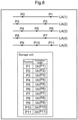
- the autonomous traveling work machine further includes a storage unit configured to store the inclination angle, wherein the storage unit stores the traveling path and the inclination angle at each of a plurality of pre-set points on the traveling path, the autonomous traveling control device performs autonomous traveling along the traveling path stored in the storage unit, and the rotation control mechanism rotates the positioning receiver at timings when the traveling machine body passes the points.
- the inclination angle of the slope can be stored at each of a plurality of points, and therefore the rotation control mechanism can be rotated at a location on the slope where the inclination angle changes a large amount during autonomous traveling, for example. Accordingly, the positioning receiver can be kept horizontal even at a location where the inclination angle changes a large amount during autonomous traveling.
- the autonomous traveling work machine further includes a communication unit configured to exchange information with an external unit, wherein the traveling path and the inclination angle are transmitted to an external terminal via the communication unit and can be displayed by the external terminal.
- a change in the inclination angle can be reported to the operator by the traveling path and the inclination angle being displayed by the external terminal. Accordingly, the operator can check the extent of the change in inclination angle and the like and switch between autonomous traveling and manual traveling of the autonomous traveling work machine.
- An autonomous traveling mowing machine includes: a traveling machine body configured to perform traveling mowing; a discharge mechanism configured to discharge cut grass from a discharge opening to a mowed ground surface; a detection device configured to detect the cut grass discharged by the discharge mechanism; a target line calculation unit configured to calculate a target line based on the detection of cut grass; and an autonomous traveling control device configured to control autonomous traveling of the traveling machine body such that a distance between the traveling machine body and the target line calculated by the target line calculation unit is maintained at a pre-set distance.
- cut grass is discharged from the discharge mechanism, and the discharged cut grass is detected by the detection device.
- the target line can be calculated with use of the discharged cut grass as a target object. Accordingly, it is possible to realize an autonomous traveling mowing machine that can calculate a target line and perform autonomous traveling based on the target line even if a target object is not located in the mowing region.
- the discharge mechanism is configured to discharge the cut grass in a form of clumped cut grass along a traveling route of the traveling machine body such that the clumped cut grass forms raised portions that are continuous or non-continuous along the traveling route of the traveling machine body.
- the cut grass is discharged in clumps, and raised portions are formed by the cut grass, thus making it possible for the detection device to accurately detect the cut grass.
- the discharge mechanism is provided at a side portion of the traveling machine body that corresponds to the mowed ground surface.
- the detection device can accurately detect cut grass that has been discharged on a flat ground surface.
- the detection device is provided at a side portion of the traveling machine body that corresponds to the mowed ground surface.
- the detection device is provided in a side portion of the traveling machine body, and therefore the detection device can detect the cut grass even if the cut grass is located directly below the detection device. Accordingly, the detection device can detect the cut grass immediately after being discharged from the discharge mechanism.
- a discharge path that extends from the traveling machine body to the discharge opening is formed in the discharge mechanism, and the discharge path is tapered such that a cross-sectional shape thereof becomes smaller toward the discharge opening.
- the cut grass before being discharged from the discharge opening, the cut grass is compressed in the discharge path that becomes narrower toward the discharge opening, and thus the cut grass is likely to be in clumps when discharged.
- the discharge mechanism is provided with a switching mechanism configured to open and close the discharge opening and a pressure detecting means for detecting a pressure of the cut grass, and the switching mechanism opens if the pressure detected by the pressure detecting means is greater than or equal to a pre-set pressure.
- the pressure of the cut grass can be raised to a pre-set pressure or higher before being discharged from the discharge opening.
- the cut grass can therefore be formed into clumps when discharged.
- a mowing machine includes: a traveling machine body configured to perform traveling mowing; a travel control unit configured to control the traveling machine body; a distance sensor configured to perform scanning to both sides in a machine body left-right direction to detect a distance between the traveling machine body and an object arranged in the machine body left-right direction; a decoding control unit configured to generate ground height data regarding both sides in the machine body left-right direction based on a scan angle and the distance detected through scanning performed by the distance sensor; an object detection unit configured to generate a ground surface reference line identified as a line indicating a mowed ground surface, and a grass reference line identified as a line indicating uncut grass, with use of an approximate line that is based on the ground height data; a target distance calculation unit configured to calculate a target distance based on a distance between the grass reference line and the traveling machine body; and a travel instruction unit configured to output an instruction signal such that the distance between the grass reference line and the traveling machine body matches the target distance.
- the mowing region includes grass that is to be mowed.
- the distance sensor operates in the left-right direction of the traveling machine body and identifies the mowed ground surface and uncut grass, and the traveling machine body is controlled such that a pre-set distance is maintained between the traveling machine body and a grass reference line that is based on the identified grass.
- the mowing machine can autonomously perform traveling mowing along the boundary between the mowed ground surface and uncut grass.
- the mowing machine further includes a travel mode determination unit configured to determine a traveling mode of the traveling machine body, wherein the traveling mode includes a manual control mode and an autonomous control mode, if the traveling mode is the manual control mode, the travel control unit controls the traveling machine body based on a manual control operation signal, and if the traveling mode is the autonomous control mode, the travel control unit controls the traveling machine body based on the instruction signal from the travel instruction unit.
- a travel mode determination unit configured to determine a traveling mode of the traveling machine body, wherein the traveling mode includes a manual control mode and an autonomous control mode, if the traveling mode is the manual control mode, the travel control unit controls the traveling machine body based on a manual control operation signal, and if the traveling mode is the autonomous control mode, the travel control unit controls the traveling machine body based on the instruction signal from the travel instruction unit.
- the mowing machine can be remotely operated in accordance with the status of the mowing region and the status of the traveling machine body. According to the above configuration, whether the signal input by the travel control unit is an operation signal in the case of the manual control mode or an instruction signal in the case of the autonomous control mode can be switched based on the determination of the traveling mode by the travel mode determination unit.
- the distance sensor is configured to perform scanning by rotating about a machine body front-rear direction.
- the scan angle of the distance sensor rotates about the front-rear direction, and therefore the distance sensor can scan a portion of the mowed ground surface that is in the region below the traveling machine body. Accordingly, the distance sensor can accurately scan the mowed ground surface and uncut grass.
- the distance sensor is provided at one of a front portion and a rear portion of the traveling machine body.
- the distance sensor can scan the ground surface directly below the distance sensor. Accordingly, the distance sensor can accurately scan the mowed ground surface and uncut grass.
- the distance sensor is provided at both a front portion and a rear portion of the traveling machine body.
- a distance sensor provided at the front portion of the traveling machine body can scan the ground surface and the grass at a position where traveling mowing has not been performed, and a distance sensor provided at the rear portion of the traveling machine body can scan the ground surface and the grass at a position where traveling mowing has been performed. Accordingly, the mowing machine can accurately travel along the boundary between the mowed ground surface and uncut grass.
- the object detection unit is configured to generate the ground surface reference line by calculating an approximate line based on, from among pieces of the ground height data, data corresponding to a pre-set range in the machine body left-right direction from a position immediately below the distance sensor with respect to a machine body vertical direction.
- the ground surface reference line is generated based on an approximate line, and therefore the mowed ground surface and uncut grass can be efficiently identified based on the ground height data.
- the object detection unit is configured to generate a grass candidate line by calculating an approximate line based on, from among pieces of the ground height data, data that indicates a height from the ground surface reference line that is greater than or equal to a certain value at a certain number of consecutive locations or more.
- the ground height data that is used for generation of grass candidate line is limited to data that is consecutive over a certain range or more. For this reason, data that is not consecutive over the range is excluded from the data for grass candidate lines, and the risk of erroneous grass detection is reduced. Also, the grass candidate lines are generated based on an approximate line, and therefore the mowed ground surface and uncut grass can be efficiently identified based on the ground height data.
- the traveling machine body is provided with an inertial sensor that detects an inclination angle of the traveling machine body
- the object detection unit specifies, as the grass reference line, one of the grass candidate lines for which an inclination angle of the grass candidate line relative to the ground surface reference line and a calculated inclination angle calculated based on the inclination angle detected by the inertial sensor are in a predetermined reference range.
- the specific direction can be calculated based on the inclination angle of the inertial sensor. For this reason, the grass identification accuracy is improved by specifying the one of the grass candidate lines that conforms to the specific direction as the grass reference line.
- the grass reference line is defined in a pre-set height range from the ground surface reference line.
- a plurality of values of the distance between the grass reference line and the traveling machine body are stored, including values calculated at a current time and a plurality of past times, and the target distance is calculated based on a moving average value of the plurality of values.
- the target distance is a moving average value, and therefore even if the distance between the grass reference line and the traveling machine body suddenly changes a large amount, the change in the target distance is smaller than the change in the distance between the grass reference line and the traveling machine body, and the instruction signal output by the travel instruction unit is stable.
- An autonomous traveling system for a mowing machine is an autonomous traveling system for a mowing machine that performs autonomous traveling mowing in a pre-set traveling area on a slope, the autonomous traveling system including: an object detection unit provided at an uppermost end of the slope and configured to detect an object by transmitting a detection signal and acquiring a reflection signal with respect to the detection signal; a reflecting portion that is provided on a side surface of the mowing machine that corresponds to the object detection unit, and that is configured to be detected by the object detection unit; communication units respectively provided in the object detection unit and the mowing machine; a storage unit configured to store area information regarding the traveling area and operation history information of the mowing machine; a traveling path setting unit configured to set a traveling path for the mowing machine; and a control instruction unit configured to transmit an instruction signal to the mowing machine, wherein the object detection unit is configured to track the reflecting portion, the control instruction unit calculates a traveling route for the mowing machine based on the reflection signal acquired by the object detection unit
- the object detection unit is provided at the uppermost end of the slope, and the reflecting portion is provided on a side surface of the mowing machine.
- the object detection unit is fixed at a fixed point position, and the mowing machine can be used as the target object to be detected by the object detection unit, and therefore the reflecting portion of the mowing machine can be detected by the object detection unit in a stable state unlike the case where the object detection unit is provided in the mowing machine.
- the object detection unit can detect the reflecting portion of the mowing machine without being influenced by the protrusions/recession or the like of the slope. Accordingly, it is possible to realize a mowing machine autonomous traveling system that enables the object detection unit to accurately track an object even if a slope has an angle of inclination that is not uniform, or has protrusions/recessions.
- the mowing machine is provided with an inclination sensor configured to detect an inclination angle of the mowing machine
- the object detection unit is provided with an inclination correction control unit configured to perform angle adjustment on the object detection unit such that an inclination angle of the object detection unit matches the inclination angle detected by the inclination sensor.
- the inclination angle detected by the inclination sensor of the mowing machine conforms to the inclination angle of the slope, and therefore with the above configuration, the inclination angle of the object detection unit is changed by the inclination correction control unit in accordance with the inclination angle of the slope. Accordingly, the adjustment of the inclination of the object detection unit does not need to be performed manually each time for different slopes, and the object detection unit can easily track the reflecting portion of the mowing machine in accordance with any of various slope angles.
- the reflecting portion is provided with a plurality of horizontally long reflective sheets that are arranged side-by-side in an up-down direction, and the reflective sheets have mutually different lengths in a lengthwise direction.
- the object detection unit when the object detection unit performs scanning in the horizontal direction, the object detection unit can detect the length of the horizontally long reflective sheets. Because the reflective sheets have mutually different lengths, the object detection unit can determine based on the lengths of the reflective sheets whether a higher position or a lower position of the reflecting portion is being tracked. Accordingly, the object detection unit can track the vertically central location of the reflecting portion, and the object detection unit can favorably track the reflecting portion even if the mowing machine suddenly moves up or down due to protrusions/recessions or the like of the slope.
- the reflective sheets are arranged such that the lengths thereof in the lengthwise direction are longer the lower the reflective sheets are located relative to a machine body.
- the difference in length is the largest between the length of the reflective sheet located at the highest position and the length of the reflective sheet located at the lowest position. For this reason, the object detection unit can easily determine whether a higher position or a lower position of the reflecting portion is being tracked, thus making it possible to suppress an erroneous determination.
- an attachment fixture configured to fix the object detection unit is provided at the uppermost end of the slope, and the object detection unit is configured to be detachably attached to the attachment fixture.
- the attachment fixture is fixed at the uppermost end of the slope, and the object detection unit can be carried, and therefore there is no need for the object detection unit to be fixedly disposed in all traveling areas. For this reason, the mowing machine autonomous traveling system can be constructed more inexpensively than in the case where the object detection unit is fixedly disposed in all traveling areas.
- the storage unit is provided in the attachment fixture, and the area information and the operation history information can be read out from the storage unit to the object detection unit in a state where the object detection unit has been fixed to the attachment fixture.
- the object detection unit can acquire information necessary for autonomous traveling mowing without needing to connect to a management computer at a remote location for example, and without needing to connect to a WAN (Wide Area Network) or the like.
- WAN Wide Area Network
- the area information and the operation history information can be stored from the object detection unit to the storage unit.
- the updated information is stored in the storage unit, and therefore the latest area information and operation history information can be read out even if a different object detection unit is used the next time autonomous traveling mowing is performed.
- operation history information regarding the current autonomous traveling mowing can be used to predict variation or the like in the inclination angle in the next instance of autonomous traveling mowing, thus making it possible to perform autonomous traveling mowing that is more stable than in past autonomous traveling mowing.
- the traveling path setting unit generates a plurality of line traveling paths that are parallel with a teaching traveling route obtained by manual operation of the mowing machine.
- the plurality of line traveling paths are arranged parallel with each other downward of the teaching traveling route in an upward-downward direction of the slope.
- the object detection unit is provided at the upper end of the slope, with the above configuration, autonomous traveling mowing is performed from the upper side of the slope to the downstream side. For this reason, the mowed ground surface is always located between the object detection unit and the mowing machine, and the object detection unit can favorably track the reflecting portion of the mowing machine without being obstructed by uncut grass.
- the teaching traveling route and the plurality of line traveling paths are stored in the storage unit as the operation history information, and based on the operation history information, the traveling path setting unit can reproduce the teaching traveling route as a line traveling path and can reproduce the plurality of line traveling paths.
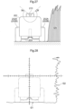
- an autonomous traveling mowing machine which serves as the autonomous traveling work machine illustrated in the present embodiment, includes a traveling machine body 1, first wheels 2A, second wheels 2B, a mowing device 3, a positioning receiver 4, and a rotation control mechanism 5.
- a pair of left and right first wheels 2A are provided on one end side of the traveling machine body 1 in the lengthwise direction.
- a pair of left and right second wheels 2B are provided on the other end side of the traveling machine body 1 in the lengthwise direction.
- the mowing device 3 is provided between the first wheels 2A and the second wheels 2B in the lower portion of the traveling machine body 1.
- the positioning receiver 4 is provided above the traveling machine body 1.
- the rotation control mechanism 5 can rotate with multiple degrees of freedom, and is provided between the positioning receiver 4 and the traveling machine body 1.
- the positioning receiver 4 is configured to receive positioning signals with use of a GNSS (Global Navigation Satellite System) for detecting the position of the machine body by receiving radio waves from navigation satellites, one example of which is GPS (Global Positioning System), which is known technology. Note that the positioning receiver 4 is not limited to using GPS, and may be configured to be compatible with GNSSes.
- a shielding plate 6 is provided between the positioning receiver 4 and the rotation control mechanism 5. The shielding plate 6 is provided at a position directly below the positioning receiver 4.
- An antenna 8 for communication with a transmitter 7 is provided on the traveling machine body 1.
- the transmitter 7 is configured to enable manual operation of the autonomous traveling work machine while being held by an operator.
- the transmitter 7 may enable operations with use of a proportional type of transmitter that is operated in the worker's hands, or may enable operations with use of a mobile terminal device that has a touch panel type of display screen.
- the traveling machine body 1 is provided with a transmission mechanism that transmits motive power from an engine EA to the first wheels 2A and the second wheels 2B, and also transmits motive power to the mowing device 3.
- the transmission mechanism is configured to be capable of engaging and disengaging the transmission of motive power to the first wheels 2A and the second wheels 2B and also to the mowing device 3. Due to motive power being transmitted from the engine EA to the first wheels 2A and the second wheels 2B and to the mowing device 3, it is possible to perform mowing while the machine body travels.
- the first wheels 2A are provided with a first steering motor 9A, and the first wheels 2A are configured to be steerable by swinging about a vertical axis with use of drive power from the first steering motor 9A.
- the second wheels 2B are provided with a second steering motor 9B, and the second wheels 2B are configured to be steerable by swinging about a vertical axis with use of drive power from the second steering motor 9B.
- the first wheels 2A and the second wheels 2B can both change orientation between any of a straight advancing orientation, a right swing orientation, and a left swing orientation.
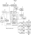
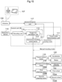
- a control unit UA which enables the autonomous traveling mowing machine to autonomously travel along a pre-set traveling path, is provided in the autonomous traveling mowing machine in the form of being integrated in a microcomputer, for example.
- the control unit UA incudes a travel mode determination unit 10, a storage unit 11, a traveling path setting unit 12, and an autonomous traveling control device 13.
- the storage unit 11 is configured to be able to store position information that is based on positioning signals received by the positioning receiver 4.
- the traveling path setting unit 12 sets traveling paths for autonomous traveling of the traveling machine body 1.
- the autonomous traveling control device 13 is configured to cause the traveling machine body 1 to travel along the traveling paths set by the traveling path setting unit 12.
- the control unit UA is also configured to enable switching between an autonomous travel mode and a manual travel mode in accordance with a determination made by the travel mode determination unit 10.
- the manual travel mode the autonomous traveling work machine performs traveling mowing and the like based on manual operations made via the transmitter 7, and therefore the autonomous traveling control device 13 is disabled, and a configuration is possible in which the traveling path setting unit 12 is also disabled in conjunction with the autonomous traveling control device 13.
- the autonomous traveling control device 13 outputs signals to a travel control motor 15, a forward/reverse motor 16, the first steering motor 9A, and the second steering motor 9B.
- the travel control motor 15 operates an accelerator 20 that adjusts the amount of fuel supplied to the engine EA, and brakes 21 that brake the first wheels 2A and the second wheels 2B.
- the forward/reverse motor 16 switches a forward/reverse switching mechanism 22.
- the forward/reverse switching mechanism 22 is provided in the transmission device that transmits motive power from the engine EA to the first wheels 2A and the second wheels 2B, and is a gear mechanism for switching the motive power from the engine EA between a forward direction and a reverse direction.
- the first steering motor 9A steers the first wheels 2A, and the second steering motor 9B steers the second wheels 2B.
- the travel control motor 15 and the forward/reverse motor 16 may each be an electric motor or an electromagnetic switch.
- the autonomous traveling control device 13 specifies the position and the direction of the traveling machine body 1 based on positioning signals received by the positioning receiver 4.
- the autonomous traveling control device 13 is configured to cause the traveling machine body 1 to travel along later-described traveling paths by outputting control signals to the travel control motor 15, the forward/reverse motor 16, the first steering motor 9A, and the second steering motor 9B.
- the autonomous traveling control device 13 is also configured to be able to switch between the autonomous travel mode, in which traveling is performed based on control signals from the control device 13, and the manual travel mode, in which traveling is performed based on control signals given through manual operations.
- the traveling machine body 1 is provided with a communication unit 17 that can receive, via the antenna 8, operation signals wirelessly transmitted by the transmitter 7.
- the information received by the communication unit 17 is input to the control unit UA.
- the status of the autonomous traveling mowing machine can be transmitted from the communication unit 17 to a device that is outside the machine body, and the current position and status of the autonomous traveling mowing machine can also be displayed on the display screen of a mobile terminal device, for example.
- the status of the autonomous traveling mowing machine may include the speed during traveling mowing, the remaining fuel amount, and problems regarding various devices included in the autonomous traveling mowing machine.
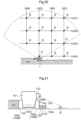
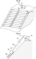
- the traveling path setting unit 12 is provided in the control unit UA. Traveling paths for autonomous traveling of the traveling machine body 1 are set in advance by the traveling path setting unit 12. As shown in FIG. 5 , multiple straight line traveling paths LA have been set as traveling paths for autonomous traveling on a slope. In the present embodiment, the line traveling paths LA are generated by the traveling path setting unit 12 through the following procedure.
- teaching traveling is performed along the upper edge portion of the slope. Teaching traveling is performed based on manual operations given through operations performed on the transmitter 7 by the operator.
- the operator while the traveling machine body 1 is located at a start position TAs, the operator performs a start position setting operation on the transmitter 7.
- the operator then steers the traveling machine body 1 along a straight line from the start position TAs to a finish position TAf, and then while the traveling machine body 1 is located at the start position TAs, the operator performs a finish position setting operation on the transmitter 7. Teaching processing is thus executed.
- this is processing for setting a teaching path TA that connects the start position TAs to the finish position TAf based on position coordinates that are based on positioning data acquired by the positioning receiver 4 at the start position TAs and position coordinates that are based on positioning data acquired by the positioning receiver 4 at the finish position TAf.
- a configuration is also possible in which the position of the traveling machine body 1 is successively measured by the positioning receiver 4 during teaching traveling, and the positioning signals are stored in the storage unit 11.
- the teaching path TA is obtained by extracting chronological position coordinates of the traveling machine body 1 from the set of positioning signals over the period from the start position TAs in teaching traveling to the finish position TAf in teaching traveling. This configuration is particularly useful in the case where the teaching path TA is curved.
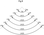
- Line traveling paths LA are then generated as traveling paths that are parallel with the teaching path TA and are at equal intervals downward along the slope.
- line traveling paths LA(1) to LA(10) that are parallel with the teaching path TA are generated at equal intervals downward from the teaching path TA on the slope. Note that taking the width of the region that is to be mowed and the mowing operation width of the work vehicle into consideration, the line traveling paths LA are set such that the operation widths are slightly overlapped in order to prevent unmowed regions from remaining.
- the line traveling paths LA(1) to LA(10) are each assigned a start position LAs and a finish position LAf, and the line traveling paths LA(1) to LA(10) are configured such that the direction from the start position LAs to the finish position LAf is the advancing direction of the traveling machine body 1. Also, a route is set such that the traveling machine body 1 travels along the line traveling paths LA(1) to LA(10) in order, and in the present embodiment, the route is set such that the traveling machine body 1 travels back and forth in straight lines from the upward side of the slope to the downward side.
- traveling paths are set such that the finish position LAf of any one line traveling path LA(n) among the line traveling paths LA(1) to LA(9) has, adjacent thereto on the slope downstream side, the start position LAs of the line traveling path LA(n+1) that has been assigned next along the route.
- the autonomous traveling mowing machine performs mowing while autonomously traveling along the line traveling paths LA.
- the autonomous traveling control device 13 outputs control signals such that the traveling machine body 1 moves to the start position LAs of the line traveling path LA(2) that has been assigned as next along the route.
- the autonomous traveling control device 13 may output control signals such that the traveling machine body 1 moves to the start position LAs of the next line traveling path LA(2) by making a U-turn, or may output control signals such that the traveling machine body 1 moves to the start position LAs of the next line traveling path LA(2) by repeatedly zig-zagging instead of turning around.
- zig-zagging in the present embodiment refers to a form of traveling in which, upon reaching the finish position LAf, the traveling machine body 1 repeatedly moves forward and rearward through switching of the forward/reverse switching mechanism 22 such that the position of the traveling machine body 1 shifts downward from the finish position LAf and arrives at the start position LAs.
- movement from the finish position LAf to the next start position LAs may be performed in the manual travel mode.
- the switch from the manual travel mode to the autonomous travel mode may be performed manually or automatically.
- the autonomous traveling mowing machine After the traveling machine body 1 has arrived at the start position LAs of the line traveling path LA(2) and the advancing direction of the traveling machine body 1 matches the advancing direction of the line traveling path LA(2), the autonomous traveling mowing machine then performs mowing while autonomously traveling along the line traveling path LA(2).
- the autonomous traveling control device 13 is configured to specify the position and the direction of the traveling machine body 1 based on positioning signals received by the positioning receiver 4, but if the autonomous traveling mowing machine of the present embodiment travels on an inclined slope, the positioning receiver 4 also becomes inclined in accordance with the inclination of the slope. Due to this inclination of the positioning receiver 4, there is a risk of a decrease in the number of navigation satellites that can communicate with the positioning receiver 4. Also, if a river or flooded paddy is located downhill of the inclined slope, the positioning receiver 4 is likely to experience multipath effects due to the positioning signals transmitted by the navigation satellites being irregularly reflected by the river or flooded paddy, and there is a risk of a decrease in the positioning accuracy.
- the distance between the positioning receiver 4 and the ground surface is often short, and the aforementioned problems are likely to arise.
- the shielding plate 6 is provided directly below the positioning receiver 4, and the shielding plate 6 shields the underside of the positioning receiver 4 from positioning signals that have been irregularly reflected by a river or flooded paddy. Accordingly, the positioning receiver 4 is not likely to experience multipath effects, and the risk of a decrease in positioning accuracy is reduced.
- the rotation control mechanism 5 for mitigating the inclining of the positioning receiver 4 is provided below the positioning receiver 4.
- the shielding plate 6 is provided below the positioning receiver 4, and the rotation control mechanism 5 is provided below the shielding plate 6, and the positioning receiver 4 and the shielding plate 6 are configured to be able to integrally swing about a rotation shaft of the rotation control mechanism 5.
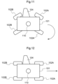
- the rotation control mechanism 5 is configured to rotate with two degrees of freedom. Specifically, the rotation control mechanism 5 is configured to be able to rotate about a roll axis that matches the chassis front-rear direction of the traveling machine body 1 and a pitch axis that matches the chassis left-right direction of the traveling machine body 1. Accordingly, the positioning receiver 4 rotates with multiple degrees of freedom. In this way, even if the traveling machine body 1 travels on an inclined slope, the rotation control mechanism 5 rotates such that positioning receiver 4 is kept in a horizontal orientation.
- An inclination angle detection unit 30 provided in the traveling machine body 1 is an IMU (Inertial Measurement Unit), which is one example of an inertial sensor, and the inclination angle detection unit 30 detects the inclination of the traveling machine body 1 and outputs inclination angle information ImA.
- An angle for holding the positioning receiver 4 in the horizontal orientation is determined by an inclination angle determination unit 31, and the inclination angle determination unit 31 determines an inclination angle IA for output to the rotation control mechanism 5 based on the inclination angle information ImA.
- the inclination angle IA includes a roll angle with respect to the chassis front-rear direction of the traveling machine body 1 and a pitch angle with respect to the chassis left-right direction of the traveling machine body 1.
- the determined inclination angle IA is output to the rotation control mechanism 5, and the rotation control mechanism 5 adjusts the rotation angle with respect to the roll axis and the pitch axis based on the input inclination angle IA.
- the inclination angle determination unit 31 can also be configured to directly use the inclination angle information ImA detected by the inclination angle detection unit 30 as the inclination angle IA, and directly output the inclination angle IA to the rotation control mechanism 5. Furthermore, the rotation control mechanism 5 can be configured to keep the positioning receiver 4 horizontal in real-time by immediately rotating the positioning receiver 4 based on the input inclination angle IA. However, in the case of this configuration, the positioning receiver 4 continuously rotates relative to the traveling machine body 1 in accordance with protrusions and recessions in the ground surface as the traveling machine body 1 travels, and there is a risk that the inclination of the positioning receiver 4 relative to the traveling machine body 1 will not be stable.
- the timing of the rotation of the positioning receiver 4 relative to the traveling machine body 1, that is to say the timing of rotation of the rotation control mechanism 5, is a timing at which the traveling machine body 1 is stopped.
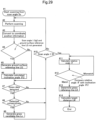
- the inclination angle detection unit 30 continuously detects the inclination angle information ImA from the start position TAs to the finish position TAf in teaching traveling, and continuously outputs the inclination angle information ImA to the inclination angle determination unit 31.
- the inclination angle determination unit 31 also calculates the average value of the inclination angle information ImA detected between the start position TAs and the finish position TAf, and sets the average value as the inclination angle IA(0).
- the rotation control mechanism 5 positions and maintains the positioning receiver 4 such that the positioning receiver 4 maintains the inclination angle IA(0) relative to the traveling machine body 1.
- the timing when the rotation control mechanism 5 rotates the positioning receiver 4 is a timing during movement of the traveling machine body 1 from the finish position TAf to the start position LAs of the first line traveling path LA(1).
- the inclination angle detection unit 30 continuously detects the inclination angle information ImA from the start position LAs to the finish position LAf of the line traveling path LA(1), and continuously outputs the inclination angle information ImA to the inclination angle determination unit 31.
- the inclination angle determination unit 31 calculates the average value of the inclination angle information ImA detected between the start position LAs and the finish position LAf of the first line traveling path LA(1), and sets the average value as the inclination angle IA(1).
- the inclination angle determination unit 31 updates the inclination angle IA from the inclination angle IA(0) to the inclination angle IA(1).
- the rotation control mechanism 5 rotates based on the inclination angle IA(1) before the traveling machine body 1 moves to the start position LAs of the next line traveling path LA(2).
- the rotation control mechanism 5 positions and maintains the positioning receiver 4 such that the positioning receiver 4 maintains the inclination angle IA(1) relative to the traveling machine body 1.
- the inclination angle detection unit 30 continuously detects the inclination angle information ImA from the start position LAs to the finish position LAf of the line traveling path LA(2), and continuously outputs the inclination angle information ImA to the inclination angle determination unit 31. Then, when the traveling machine body 1 has arrived at the finish position LAf of the line traveling path LA(2), the inclination angle determination unit 31 updates the inclination angle IA from the inclination angle IA(1) to the inclination angle IA(2).
- the rotation control mechanism 5 positions and maintains the positioning receiver 4 at the inclination angle IA(n-1) that was determined on the immediately previous traveling path LA(n-1).
- the difference between the inclination angles of the slope on the adjacent line traveling paths LA(n-1) and LA(n) is often smaller than the difference between the inclination angles of the slope on two distant line traveling paths LA that are not adjacent to each other.
- the positioning receiver 4 can be kept approximately horizontal with use of the inclination angle IA(n-1) on the immediately previously line traveling path LA(n-1).
- the transmitter 7 is a mobile terminal device or the like and has a display screen
- the transmitter 7 is configured to be able to receive the inclination angle information ImA and the inclination angle IA via the communication unit 17 and display them on the display screen. Traveling paths including the teaching traveling route and the line traveling paths LA can also be displayed on the display screen.
- the present invention is not limited to the configurations illustrated in the above embodiment, and the following are representative variations of the present invention.
- an autonomous traveling mowing machine which serves as the autonomous traveling work machine illustrated in the present embodiment, includes a traveling machine body 101, first wheels 102A, second wheels 102B, and a mowing device 103.
- a pair of left and right first wheels 102A are provided on one end side of the traveling machine body 101 in the lengthwise direction.
- a pair of left and right second wheels 102B are provided on the other end side of the traveling machine body 101 in the lengthwise direction.
- the mowing device 103 is provided between the first wheels 102A and the second wheels 102B in the lower portion of the traveling machine body 101.
- a discharge mechanism 104 see FIGS.
- a detection device 110 is provided at an upper portion of the traveling machine body 101. The detection device 110 will be described later.
- An antenna 108 for communication with a transmitter 107 is provided at an upper portion of the traveling machine body 101.
- the transmitter 107 is configured to enable manual operation of the autonomous traveling work machine while being held by an operator.
- the transmitter 107 may enable operations with use of a proportional type of transmitter that is operated in the worker's hands, or may enable operations with use of a mobile terminal device that has a touch panel type of display screen.
- the traveling machine body 101 is provided with a transmission mechanism that transmits motive power from an engine EB to the first wheels 102A and the second wheels 102B, and also transmits motive power to the mowing device 103.
- the transmission mechanism is configured to be capable of engaging and disengaging the transmission of motive power to the first wheels 102A and the second wheels 102B and also to the mowing device 103. Due to motive power being transmitted from the engine EB to the first wheels 102A and the second wheels 102B and to the mowing device 103, it is possible to perform mowing while the machine body travels.
- the first wheels 102A are provided with a first steering motor 109A, and the first wheels 102A are configured to be steerable by swinging about a vertical axis with use of drive power from the first steering motor 109A.
- the second wheels 102B are provided with a second steering motor 109B, and the second wheels 102B are configured to be steerable by swinging about a vertical axis with use of drive power from the second steering motor 109B.
- the first wheels 102A and the second wheels 102B can both change orientation between any of a straight advancing orientation, a right swing orientation, and a left swing orientation.
- the discharge mechanism 104 is provided in a state of protruding from either the left or right side portion of the traveling machine body 101.
- dotted regions GNB denote unmowed regions in a mowing region. This similarly applies to regions GNB shown in later-described FIGS. 16 to 22 as well.
- the discharge mechanism 104 is provided on the side of the traveling machine body 101 that corresponds to the mowed ground surface.
- a discharge opening 104a is formed in the protruding leading end portion of the discharge mechanism 104.
- the discharge mechanism 104 is also provided with a discharge path 104b that extends between a discharge opening 101b of the traveling machine body 101 and the discharge opening 104a of the discharge mechanism 104.
- the discharge path 104b has a tapered shape according to which the cross-sectional shape thereof becomes smaller as it extends toward the discharge opening 104a. According to this shape, grass cut by the mowing device 103 enters the discharge path 104b through the discharge opening 101b and is then compressed on the discharge opening 104a side and becomes clumped cut grass G.
- the discharge opening 104a is provided with a switching mechanism 141 for opening and closing the discharge opening 104a.
- a pressure sensor 142 pressure detecting means
- the switching mechanism 141 is configured to be able to switch between an open state in which the discharge opening 104a is open, and a closed state in which the discharge opening 104a is closed.
- the pressure sensor 142 is a switch that activates when subjected to a pressure greater than or equal to a pre-set pressure for example, and the switching mechanism 141 is configured to be in the open state while the pressure sensor 142 is activated.
- cut grass that passes through the discharge path 104b which has a tapered shape, is further compressed into clumps at a stage before being discharged from the discharge opening 104a.
- the switching mechanism 141 may be configured to perform switching with use of an electric motor, or may be configured to perform switching with use of an electromagnetic switch.
- the pressure sensor 142 may be a load cell, or may be a spring-type switch that activates due to the pressure of cut grass resisting biasing force.
- the discharge mechanism 104 is provided on the side of the traveling machine body 101 that corresponds to the mowed ground surface. For this reason, while the traveling machine body 101 is performing traveling mowing, the cut grass is discharged in clumps from the discharge opening 104a to the mowed ground surface, and thus a straight line of clumped cut grass G is formed on the mowed ground surface. In other words, a continuous raised portion that extends along the traveling route of the traveling machine body 101 is formed by the clumped cut grass G on the mowed ground surface. There are also cases where non-continuous portions of the clumped cut grass G are formed on the mowed ground surface due to switching between the open state and the closed state in the switching mechanism 141.
- non-continuous raised portions that extend along the traveling route of the traveling machine body 101 are also formed.
- a continuous or non-continuous line is formed by the raised portion(s) made up of clumped cut grass G on the mowed ground surface.
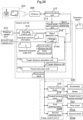
- a control unit UB which enables the autonomous traveling mowing machine to autonomously travel along a pre-set traveling path, is provided in the autonomous traveling mowing machine in the form of being integrated in a microcomputer, for example.
- the control unit UB incudes a travel mode determination unit 111, a target line calculation unit 112, an autonomous traveling control device 113, and a decoding unit 114.
- the target line calculation unit 112 sets target lines LB for autonomous traveling of the traveling machine body 101.
- the autonomous traveling control device 113 is configured to cause the traveling machine body 101 to travel parallel with the target lines LB set by the target line calculation unit 112.
- the decoding unit 114 converts detection signals detected by the detection device 110 into data for calculation of the target lines LB by the target line calculation unit 112.
- the control unit UB is also configured to enable switching between an autonomous travel mode and a manual travel mode in accordance with a determination made by the travel mode determination unit 111.
- the manual travel mode the autonomous traveling work machine performs traveling mowing and the like based on manual operations made via the transmitter 107, and therefore the autonomous traveling control device 113 is disabled, and a configuration is possible in which the target line calculation unit 112 is also disabled in conjunction with the autonomous traveling control device 113.
- the autonomous traveling control device 113 outputs signals to a travel control motor 115, a forward/reverse motor 116, the first steering motor 109A, and the second steering motor 109B.
- the travel control motor 115 operates an accelerator 120 that adjusts the amount of fuel supplied to the engine EB, and brakes 121 that brake the first wheels 102A and the second wheels 102B.
- the forward/reverse motor 116 switches a forward/reverse switching mechanism 122.
- the forward/reverse switching mechanism 122 is provided in the transmission device that transmits motive power from the engine EB to the first wheels 102A and the second wheels 102B, and is a gear mechanism for switching the motive power from the engine EB between a forward direction and a reverse direction.
- the first steering motor 109A steers the first wheels 102A
- the second steering motor 109B steers the second wheels 102B.
- the travel control motor 115 and the forward/reverse motor 116 may each be an electric motor or an electromagnetic switch.
- the traveling machine body 101 is provided with a communication unit 117 that can receive, via the antenna 108, operation signals wirelessly transmitted by the transmitter 107.
- the information received by the communication unit 117 is input to the control unit UB.
- the status of the autonomous traveling mowing machine can be transmitted from the communication unit 117 to a device that is outside the machine body, and the current position and status of the autonomous traveling mowing machine can also be displayed on the display screen of a mobile terminal device, for example.
- the status of the autonomous traveling mowing machine may include the speed during traveling mowing, the remaining fuel amount, and problems regarding various devices included in the autonomous traveling mowing machine.
- the detection device 110 is provided at an upper portion of the traveling machine body 101.
- the detection device 110 is an LRF (Laser Range Finder) for example, and transmits an air-propagating signal, such as laser beams, as a detection signal.
- LRF Laser Range Finder
- the detection device 110 acquires, as a reflection signal, the detection signal that was reflected by the surface of the detection object.
- the detection device 110 transmits a detection signal toward a detection range of the detection device 110, and acquires a reflection signal with respect to the detection signal.
- the detection device 110 is configured to then calculate the distance between the detection device 110 and the detection object based on the time from transmission of the detection signal to the acquisition of the reflection signal.
- the process in which the detection device 110 transmits a detection signal and acquires a reflection signal is hereinafter called "scanning".
- the detection device 110 performs detection by scanning the linear shape of a raised portion formed by clumped cut grass G.
- the ground height of the raised portion is then calculated by the decoding unit 114 based on the distance detected through scanning and the scan angle of the detection device 110. According to this configuration, it is possible to distinguish between the mowed ground surface and the clumped cut grass G.
- the target line calculation unit 112 recognizes the clumped cut grass G detected through scanning performed by the detection device 110, and calculates a target line LB. Specifically, using the clumped cut grass G as a target object, the target line calculation unit 112 calculates a target line LB based on the linear shape of the clumped cut grass G. Note that if the clumped cut grass G is non-continuous, and the linear shape of the clumped cut grass G is non-continuous, the target line calculation unit 112 calculates the target line LB by performing linear interpolation on the non-continuous linear shape with use of an approximate line.
- traveling mowing is performed in the manual travel mode in the mowing region to obtain a region of mowed ground surface.
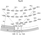
- traveling mowing is performed in teaching traveling, and clumped cut grass G(1) is formed in a line or spots on the mowed ground surface. Accordingly, portions of clumped cut grass G(1) are formed on the mowed ground surface, and each portion of clumped cut grass G(1) is used as a target object for setting of a target line LB(1) by the target line calculation unit 112.
- a linear shape is formed by the line of portions of clumped cut grass G(1)
- the detection device 110 can detect each portion of clumped cut grass G(1) through scanning, and the target line LB(1) can be calculated by the target line calculation unit 112.
- spots of clumped cut grass G(1) are formed, and the linear shape of the line of spots is non-continuous, but a configuration is possible in which a line of clumped cut grass G(1) is formed, and the linear shape thereof is continuous.
- the discharge mechanism 104 is provided on the side of the traveling machine body 101 that corresponds to the mowed ground surface. For this reason, even after teaching traveling is complete, the discharge mechanism 104 needs to autonomously travel in order to be able to continuously discharge the clumped cut grass G from the side corresponding to the mowed ground surface. In view of this, the traveling machine body 101 needs to autonomously travel without turning, such that the discharge mechanism 104 does not face the side corresponding to the unmowed region GNB. In other words, traveling mowing is performed while the traveling machine body 101 zig-zags, that is to say, while the traveling machine body 101 repeatedly moves forward and rearward.
- the terminal end of the line of clumped cut grass G(1) formed on the mowed ground surface through teaching traveling is used as the start point of the target line LB that is to be calculated by the target line calculation unit 112. Also, the start end of the line of clumped cut grass G(1) formed on the mowed ground surface through teaching traveling is used as the end point of the target line LB that is to be calculated by the target line calculation unit 112.
- the mode is switched to the autonomous travel mode such that traveling mowing is performed autonomously, and this switch from the manual travel mode to the autonomous travel mode may be made manually or automatically.
- the detection device 110 continuously performs periodic scanning in order to detect the clumped cut grass G(1) that was discharged during teaching traveling, and the target line calculation unit 112 continues to calculate the target line LB(1) based on an approximate line that approximates the clumped cut grass G(1) detected by the detection device 110.
- the target line calculation unit 112 continues to update the target line LB(1) by continuously calculating the target line LB(1).
- the target line calculation unit 112 may be configured to calculate the target line LB(1) based on the moving average of previous approximate lines that were periodically calculated.
- the autonomous traveling control device 113 calculates the distance between the target line LB(1) and the traveling machine body 101 based on the scanning performed by the detection device 110.
- the autonomous traveling control device 113 outputs control signals to the travel control motor 115, the forward/reverse motor 116, the first steering motor 109A, and the second steering motor 109B such that the traveling machine body 101 keeps a pre-set distance Pd from the target line LB(1).
- the traveling machine body 101 is located on the side opposite to the side corresponding to the clumped cut grass G(1) while adjacent to the traveling route of traveling mowing in the teaching traveling.
- the distance Pd which is the distance from the center of the operation width of the mowing device 103 to the target line LB(1) is approximately 1.5 times the operation width in traveling mowing. Note that in order to prevent unmowed regions from remaining during traveling mowing before and after the completion of teaching traveling, the operation width in traveling mowing along the target line LB(1) may be partially overlapped with the operation width in traveling mowing during teaching traveling. In other words, the distance Pd can be changed as appropriate.
- new clumped cut grass G(2) is discharged from the discharge opening 104a, and the new clumped cut grass G(2) forms a continuous or non-continuous line on the mowed ground surface and becomes a new target object for the calculation of the next target line LB(2) by the target line calculation unit 112.
- the new clumped cut grass G(2) is shifted more to the side corresponding to the traveling machine body 101 than the clumped cut grass G(1) discharged during teaching traveling is, and therefore a new straight line is formed on the mowed ground surface by the raised portion formed by the new clumped cut grass G(2).
- the target line calculation unit 112 continues on to calculate the next target line LB(2) based on an approximate line of the clumped cut grass G(2).
- the autonomous travel mode may be continued, or the mode may be switched to the manual travel mode.
- the traveling machine body 101 reverses the advancing direction, and the autonomous traveling control device 113 performs control such that autonomous traveling is performed along the next target line LB(2).
- the detection device 110 continuously performs periodic scanning, and detects the clumped cut grass G(2) discharged during teaching traveling, and the target line calculation unit 112 continues to calculate the target line LB(2) based on an approximate line of the clumped cut grass G(2) detected by the detection device 110. In other words, similarly to the case in which autonomous traveling was performed along the target line LB(1), the target line calculation unit 112 continues to update the target line LB(2) by continuously calculating the target line LB(2).
- the autonomous traveling control device 113 calculates the distance between the target line LB(2) and the traveling machine body 101 based on the scanning performed by the detection device 110.
- the autonomous traveling control device 113 outputs control signals to the travel control motor 115, the forward/reverse motor 116, the first steering motor 109A, and the second steering motor 109B such that the traveling machine body 101 keeps a pre-set distance Pd from the target line LB(2).
- new clumped cut grass G(3) is discharged from the discharge opening 104a, and the new clumped cut grass G(3) forms a continuous or non-continuous line on the mowed ground surface.
- the new clumped cut grass G(3) is discharged at a location adjacent to the clumped cut grass G(2), and a new line is formed on the mowed ground surface.
- the clumped cut grass G(3) becomes a new target object for calculation of the next target line LB(3) by the target line calculation unit 112.
- the autonomous traveling mowing machine is configured to calculate target lines LB as paths for autonomous traveling based on clumped cut grass G arranged in a line.
- the transmitter 107 may be configured to be able to receive information regarding the target lines LB and deviation of the traveling machine body 101 via the communication unit 117 and display such information on the display screen.
- the present invention is not limited to the configurations illustrated in the above embodiment, and the following are representative variations of the present invention.
- a mowing machine illustrated in the present embodiment includes a traveling machine body 201, first wheels 202A, second wheels 202B, and a mowing device 203.
- a pair of left and right first wheels 202A are provided on one end side of the traveling machine body 201 in the lengthwise direction.
- a pair of left and right second wheels 202B are provided on the other end side of the traveling machine body 201 in the lengthwise direction.
- the mowing device 203 is provided between the first wheels 202A and the second wheels 202B in the lower portion of the traveling machine body 201.
- An antenna 208 for communication with a transmitter 207 is provided at an upper portion of the traveling machine body 201.
- the transmitter 207 is configured to enable manual operation of the mowing machine while being held by an operator.
- the transmitter 207 may enable operations with use of a proportional type of controller that is operated in the worker's hands, or may enable operations with use of a mobile terminal device that has a touch panel type of display screen.
- the traveling machine body 201 is provided with a transmission mechanism that transmits motive power from an engine EC to the first wheels 202A and the second wheels 202B, and also transmits motive power to the mowing device 203.
- the transmission mechanism is configured to be capable of engaging and disengaging the transmission of motive power to the first wheels 202A and the second wheels 202B and also to the mowing device 203. Due to motive power being transmitted from the engine EC to the first wheels 202A and the second wheels 202B and to the mowing device 203, it is possible to perform mowing while the machine body travels.
- the first wheels 202A are provided with a first steering motor 209A, and the first wheels 202A are configured to be steerable by swinging about a vertical axis with use of drive power from the first steering motor 209A.
- the second wheels 202B are provided with a second steering motor 209B, and the second wheels 202B are configured to be steerable by swinging about a vertical axis with use of drive power from the second steering motor 209B.
- the first wheels 202A and the second wheels 202B can both change orientation between any of a straight advancing orientation, a right swing orientation, and a left swing orientation.
- a distance sensor 210 is provided at a front upper portion or a rear upper portion of the traveling machine body 201.
- the distance sensor 210 is an LRF (Laser Range Finder) for example, and transmits an air-propagating signal, such as laser beams or ultrasonic waves, as a detection signal.
- LRF Laser Range Finder
- the distance sensor 210 acquires, as a reflection signal, the detection signal that was reflected by the surface of the detection object.
- the distance sensor 210 transmits a detection signal toward a detection range of the distance sensor 210, and acquires a reflection signal with respect to the detection signal.
- the distance sensor 210 is configured to then calculate the distance between the distance sensor 210 and the detection object based on the time from transmission of the detection signal to the acquisition of the reflection signal.
- the process in which the distance sensor 210 transmits a detection signal and acquires a reflection signal is hereinafter called "scanning".
- An inclination angle detection unit 211 provided in the traveling machine body 201 is an IMU (Inertial Measurement Unit), which is one example of an inertial sensor, and the inclination angle detection unit 211 detects the inclination of the traveling machine body 201 and outputs inclination angle information ImC.
- IMU Inertial Measurement Unit
- a control unit UC which enables the mowing machine to autonomously travel, is provided in the mowing machine in the form of being integrated in a microcomputer, for example.
- the control unit UC is provided with a decoding control unit 212, a travel mode determination unit 213, an object detection unit 214, a target distance calculation unit 215, and a travel instruction unit 216.
- the decoding control unit 212 calculates coordinate position information that includes a horizontal distance from the distance sensor 210 in the machine body left-right direction and a vertical distance from the distance sensor 210 in the machine body up-down direction, based on distances calculated through scanning performed by the distance sensor 210 and scan angles during calculation.
- the control unit UC is also configured to enable switching between an autonomous travel mode and a manual travel mode, and whether the current mode is the autonomous travel mode or the manual travel mode is determined in accordance with a determination made by the travel mode determination unit 213.
- the object detection unit 214 generates a ground surface reference line LG, which is an approximate straight line that represents the mowed ground surface based on coordinate position information, and a grass reference line LK, which is an approximate straight line that represents a line of uncut grass.
- the object detection unit 214 is provided with a storage unit 214a, and the storage unit 214a is a RAM (Random Access Memory) or the like that chronologically stores the coordinate position information calculated by the decoding control unit 212.
- the ground surface reference line LG and the grass reference line LK are generated using the coordinate position information stored in the storage unit 214a.
- the target distance calculation unit 215 calculates the separation distance between the grass reference line LK and the distance sensor 210.
- the target distance calculation unit 215 also calculates a target distance LM, which is for causing the traveling machine body 201 to favorably perform traveling mowing while keeping a separation distance between the position of the distance sensor 210 and the grass reference line LK.
- the travel instruction unit 216 outputs a control signal such that the separation distance between the grass reference line LK and the distance sensor 210 is maintained at the target distance LM.
- the traveling machine body 201 is provided with a communication unit 217 that can receive, via the antenna 208, operation signals wirelessly transmitted by the transmitter 207.
- the information received by the communication unit 217 is input to the control unit UC.
- traveling mowing and the like is performed based on manual operations made via the transmitter 207.
- the travel instruction unit 216 is therefore disabled in the manual travel mode, and a configuration is possible in which the object detection unit 214 and the target distance calculation unit 215 are also disabled in conjunction with the travel instruction unit 216.
- the travel instruction unit 216 outputs signals to a travel control unit C, and the travel control unit C is provided with a travel control motor 218, a forward/reverse motor 219, the first steering motor 209A, and the second steering motor 209B.
- the travel control motor 218 operates an accelerator 220 that adjusts the amount of fuel supplied to the engine EC, and brakes 221 that brake the first wheels 202A and the second wheels 202B.
- the forward/reverse motor 219 switches a forward/reverse switching mechanism 222.
- the forward/reverse switching mechanism 222 is provided in the transmission device that transmits motive power from the engine EC to the first wheels 202A and the second wheels 202B, and is a gear mechanism for switching the motive power from the engine EC between a forward direction and a reverse direction.
- the first steering motor 209A steers the first wheels 202A
- the second steering motor 209B steers the second wheels 202B.
- the travel control motor 218 and the forward/reverse motor 219 may each be an electric motor or an electromagnetic switch.
- the travel control unit C When the travel mode is the autonomous travel mode, the travel control unit C performs control based on instruction signals from the travel instruction unit 216.
- the travel mode is the manual travel mode, operation signals that are based on manual operations made on the transmitter 207 are input to the travel control unit C via the communication unit 217 and the travel mode determination unit 213, and the travel control unit C performs control based on such operation signals.
- the status of the mowing machine can be transmitted from the communication unit 217 to a device that is outside the machine body, and the current position and status of the mowing machine can also be displayed on the display screen of a mobile terminal device, for example.
- the status of the mowing machine may include the speed during traveling mowing, the remaining fuel amount, and problems regarding various devices included in the mowing machine.
- the distance sensor 210 when the mowing machine performs mowing while autonomously traveling, the distance sensor 210 performs scanning while rotating about the front-rear direction of the traveling machine body 201 so as to acquire the separation distance of the distance sensor 210 from the ground surface and uncut grass (region denoted by GNC in FIG. 27 ).
- the scanning performed by the distance sensor 210 is performed in the counter-clockwise direction shown in FIG. 27 over a scan angle range of 270 degrees between a scan angle Ss and a scan angle Sf, which are respectively angles of 45 degrees to the left and right of the vertically upward direction of the machine body.
- the inclination angles of the scan angle Ss and the scan angle Sf can be changed as appropriate, and are not required to be the same inclination angle.
- the decoding control unit 212 converts the scan angles and the distance information into a horizontal distance from the distance sensor 210 in the machine body left-right direction and a vertical distance from the distance sensor 210 in the machine body up-down direction. Accordingly, the distance information acquired through scanning performed by the distance sensor 210 over time is successively converted into two-dimensional coordinate position information, and the set of coordinate position information is stored in the storage unit 214a provided in the object detection unit 214.
- the set of two-dimensional coordinate position information is expressed as a waveform as shown in FIG. 28 , and this waveform is a digital waveform plotted based on the set of coordinate position information.
- the coordinate center is the rotation axis center of the scan angle of the distance sensor 210.
- the waveform extending in the left-right direction below the coordinate center is a ground surface line G1 that indicates the mowed ground surface, and the waveform extending in the up-down direction to the right of the coordinate center is an uncut grass line G2 that indicates uncut grass. Accordingly, ground height data with respect to the uncut grass line G2 and the ground surface line G1 is obtained.
- the uncut grass line G2 in FIG. 28 is located at a distance from the side portion of the machine body, this is merely one example.
- the distance sensor 210 is located at the front end portion of the traveling machine body 201, given that uncut grass exists in front of the machine body, the uncut grass line G2 would be thought to be located at a position overlapped with the machine body.
- the distance sensor 210 is located at the rear end portion of the traveling machine body 201, the uncut grass line G2 would be thought to be located at a position contact with a horizontal side portion of the machine body.
- scanning starts at the scan angle Ss, moves over the ground surface, and then ends at the scan angle Sf, and this scanning from the scan angle Ss to the scan angle Sf is performed repeatedly.
- the scanning performed by the distance sensor 210 starts at the scan angle Ss (step #1).
- the scanning continues as the distance sensor 210 rotates over various scan angles (step #2), the distance information acquired through scanning is associated with the scan angles at which scanning was performed, and such information is successively converted into two-dimensional coordinate position information by the decoding control unit 212 (step #3).
- the processing of step#2 and the processing of step #3 continue until the scan angle of the distance sensor 210 reaches the scan angle Sf.
- the ground surface reference line LG which is identified as the mowed ground surface line, is generated by the object detection unit 214 (step #5).
- the generated ground surface reference line LG is an approximate straight line that is based on coordinate information that corresponds to the range between a scan angle Sg1 of the distance sensor 210 and the scan angle Sg2 of the distance sensor 210.
- the coordinate position information in a range between distances d1 and d2 from the ground surface reference line LG in the up-down direction is identified as ground surface coordinate position information (ground surface data).
- the scan angle Sg1 and the scan angle Sg2 are bilaterally symmetrically inclined from a scan angle Sb at which the distance sensor 210 faces vertically downward relative to the traveling machine body 201.
- the scan angle Sg1 and the scan angle Sg2 are inclined 10 degrees to the left and right of the scan angle Sb, but these inclination angles can be changed as appropriate, and may be an inclination angles that correspond to the left-right width of the traveling machine body 201, for example.
- the scan angle Sg1 and the scan angle Sg2 are not required to be bilaterally symmetric about the scan angle Sb.
- the distances d1 and d2 from the ground surface reference line LG in the up-down direction are both set to 10 cm for example, but this value can be changed as appropriate. Also, the distances d1 and d2 are not required to be the same value.
- a calculated uncut grass inclination angle ⁇ 2 relative to the mowed ground surface is calculated by the object detection unit 214 (step #6).
- a mowed ground surface inclination angle ⁇ 1 is calculated based on the detected inclination angle ImC output by the inclination angle detection unit 211.
- the inclination angle ⁇ 1 may be the instantaneous measurement value of the detected inclination angle ImC, or may be the average value of multiple past detected inclination angles ImC that were output periodically.
- the calculated uncut grass inclination angle ⁇ 2 relative to the mowed ground surface is calculated using the following expression.
- calculated inclination angle ⁇ 2 90 ° ⁇ ⁇ 1
- the distance sensor 210 continues to perform scanning, and the object detection unit 214 determines whether or not the coordinate position information, which is based on the scanning performed by the distance sensor 210, is grass coordinate position information (grass data) (step #7).
- the coordinate position information in the range between distances d1 and d2 from the ground surface reference line LG in the up-down direction is identified as the ground surface data. For this reason, the object detection unit 214 determines that the coordinate position information outside the range between the distances d1 and d2 is grass data.
- the object detection unit 214 determines whether or not a pre-set number of grass data pieces have been detected consecutively (step #8). If the pre-set number of grass data pieces have been detected consecutively (step #8: Yes), the object detection unit 214 generates a grass candidate line Lc based on that grass data (step #9). The number of consecutive detections used to determine whether or not the grass candidate line Lc can be generated can be changed as appropriate in accordance with the weather, the season, and the type of uncut grass. The object detection unit 214 generates multiple grass candidate lines Lc before the scan angle of the distance sensor 210 reaches the scan angle Sf. FIG.
- FIG. 32 shows a state in which four grass candidate lines Lc have been generated, from a grass candidate line Lc(1) that is closest to the side corresponding to the ground surface reference line LG to a grass candidate line Lc(4) that is farthest from the side corresponding to the ground surface reference line LG.
- the number of grass candidate lines Lc generated by the object detection unit 214 can be changed as appropriate.
- the object detection unit 214 When the scan angle of the distance sensor 210 reaches the scan angle Sg2 (step #10: Yes), the scanning performed by the distance sensor 210 ends. Thereafter, the object detection unit 214 repeatedly performs the processing of step #10 and the processing of step #11. Specifically, the inclination angle from the ground surface reference line LG (hereinafter, called the "relative angle ⁇ ") is calculated for each grass candidate line Lc (step #11). The object detection unit 214 then compares the relative angle ⁇ and the calculated inclination angle ⁇ 2 (step #12). If the relative angle ⁇ is within a pre-set range from the calculated inclination angle ⁇ 2 (step #12: match), the object detection unit 214 sets the corresponding grass candidate line Lc as the grass reference line LK (step #13).
- the grass reference line LK is based on the grass candidate line Lc(2).
- the object detection unit 214 determines that the relative angle ⁇ of the grass candidate line Lc(2) from the ground surface reference line LG is within the pre-set range from the calculated inclination angle ⁇ 2, and that grass candidate line Lc is set as the grass reference line LK.
- the object detection unit 214 may be configured to set, as the grass reference line LK, the first grass candidate line Lc whose relative angle ⁇ was determined to be within the pre-set range from the calculated inclination angle ⁇ 2. Also, the object detection unit 214 may be configured to calculate the relative angle ⁇ from the ground surface reference line LG for all of the grass candidate line Lc, and then set the grass candidate line Lc whose relative angle ⁇ mostly closely approximates the calculated inclination angle ⁇ 2 as the grass reference line LK.
- the target distance calculation unit 215 calculates an intersection S between the ground surface reference line LG and the grass reference line LK.
- the separation distance between the intersection S and the distance sensor 210 is then calculated, and a target distance LM that is favorable for traveling mowing of the traveling machine body 201 is calculated within the separation distance between the intersection S and the traveling machine body 201 (step #14).
- the target distance LM favorable for traveling mowing of the traveling machine body 201 can be determined based on the inclination angle of the ground surface and the type and height of the uncut grass, the attachment position of the distance sensor 210 on the traveling machine body 201, the advancing direction of the traveling machine body 201, and the like.
- step #1 to step #14 the processing from step #1 to step #14 is periodically performed once each time the distance sensor 210 makes one full rotation over the scan angles. Also, in order to suppress fluctuation of the target distance LM, a configuration is possible in which the target distance LM is calculated based on the moving average of multiple past target distances that were calculated periodically.
- the present invention is not limited to the configurations illustrated in the above embodiment, and the following are representative variations of the present invention.
- the mowing machine autonomous traveling system of the present embodiment includes an object detection unit 301, an attachment fixture 302, and a mowing machine 303.
- the object detection unit 301 is disposed at the upper end portion of a slope, and is configured to detect the position of the mowing machine 303 as it travels on the slope.
- the object detection unit 301 is used in a state of being attached to the attachment fixture 302.
- the object detection unit 301 includes a distance sensor 311, a rotation control mechanism 312, and an attachment portion 313.
- a control unit is provided in the object detection unit 301 in the form of being integrated in a microcomputer, for example.
- the distance sensor 311 is provided in an upper portion of the object detection unit 301.
- the rotation control mechanism 312 can rotate with multiple degrees of freedom, and is provided in a lower portion of the object detection unit 301.
- the attachment portion 313 is provided on a lower end of the rotation control mechanism 312, and is the attachment location for attachment of the object detection unit 301 to the attachment fixture 302.
- the attachment fixture 302 is disposed in a state of being fixed at the uppermost end of the slope.
- the attachment portion 313 of the object detection unit 301 is detachably locked to the upper end portion of the attachment fixture 302, and thus the object detection unit 301 is attached to the attachment fixture 302 and fixed at a fixed point position.
- the structure and method for attachment and detachment of the attachment portion 313 can be selected as appropriate from among known structures and methods.
- the attachment fixture 302 is provided with a storage unit 321 such as an RFID (Radio Frequency Identifier) tag, and area information for traveling mowing of the mowing machine 303, operation history information of the mowing machine 303, and the like are stored in the storage unit 321 through data communication with the control unit provided in the object detection unit 301.
- a storage unit 321 such as an RFID (Radio Frequency Identifier) tag
- area information for traveling mowing of the mowing machine 303, operation history information of the mowing machine 303, and the like are stored in the storage unit 321 through data communication with the control unit provided in the object detection unit 301.
- the object detection unit 301 accesses the storage unit 321 of the attachment fixture 302 and checks whether or not the storage unit 321 includes area information and operation history information. If the storage unit 321 has area information and operation history information, that area information and operation history information are read out to a RAM (Random Access Memory; not shown) provided in the object detection unit 301, for example. Also, if the area information and the operation history information are updated during autonomous traveling mowing, the updated information is sent from the RAM of the object detection unit 301 to the storage unit 321 and stored therein. Accordingly, even if a different object detection unit 301 is used when autonomous traveling mowing is performed the next time, the latest area information and operation history information can be read out to that different object detection unit 301.
- a RAM Random Access Memory
- the mowing machine 303 is configured to mow uncut grass GN while autonomously traveling along line traveling paths LD, which are pre-set traveling paths on a slope, based on instruction signals Tc transmitted by the object detection unit 301.
- the mowing machine 303 includes a traveling machine body 331, first wheels 332A, second wheels 332B, a mowing device 333, and a reflecting portion 334.
- a pair of left and right first wheels 332A are provided on one end side of the traveling machine body 331 in the lengthwise direction.
- a pair of left and right second wheels 332B are provided on the other end side of the traveling machine body 331 in the lengthwise direction.
- the mowing device 333 is provided between the first wheels 332A and the second wheels 332B in the lower portion of the traveling machine body 331.
- An antenna 335 for communication with a transmitter 304 (see FIG. 39 ) and the object detection unit 301 is provided at an upper portion of the mowing machine 303.
- the traveling machine body 331 is provided with a transmission mechanism that transmits motive power from an engine ED to the first wheels 332A and the second wheels 332B, and also transmits motive power to the mowing device 333.
- the transmission mechanism is configured to be capable of engaging and disengaging the transmission of motive power to the first wheels 332A and the second wheels 332B and also to the mowing device 333. Due to motive power being transmitted from the engine ED to the first wheels 332A and the second wheels 332B and to the mowing device 333, it is possible to perform mowing while the machine body travels.
- the first wheels 332A are provided with a first steering motor 332C, and the first wheels 332A are configured to be steerable by swinging about a vertical axis with use of drive power from the first steering motor 332C.
- the second wheels 332B are provided with a second steering motor 332D, and the second wheels 332B are configured to be steerable by swinging about a vertical axis with use of drive power from the second steering motor 332D.
- the first wheels 332A and the second wheels 332B can both change orientation between any of a straight advancing orientation, a right swing orientation, and a left swing orientation.
- the distance sensor 311 is an LRF (Laser Range Finder), a LIDAR (Light Detection and Ranging), or the like, and transmits an air-propagating signal, such as laser beams or ultrasonic waves, as a detection signal TW.
- an air-propagating signal such as laser beams or ultrasonic waves
- the detection signal TW strikes a detection object
- the detection signal TW is reflected by the surface of the detection object.
- the distance sensor 311 acquires, as a reflection signal RW, the detection signal TW that was reflected by the surface of the detection object.
- the distance sensor 311 transmits the detection signal TW toward a detection range of the distance sensor 311, and acquires the reflection signal RW with respect to the detection signal TW.
- the distance sensor 311 is configured to then calculate the distance between the distance sensor 311 and the detection object based on the time from transmission of the detection signal TW to the acquisition of the reflection signal RW.
- the process in which the distance sensor 311 transmits the detection signal TW and acquires the reflection signal RW is hereinafter called “scanning".
- the distance sensor 311 is configured to be able to perform scanning in a scan angle range of 270 degrees over a radial distance range of several tens of meters in a plan view. Accordingly, if multiple attachment fixtures 302 are disposed, the attachment fixtures 302 are disposed at intervals corresponding to the scan range of the distance sensor 311.
- the reflecting portion 334 is a detection object that reflects the detection signal TW emitted by the distance sensor 311.
- the reflecting portion 334 is configured to reflect the reflection signal RW in the same direction as the direction of incidence of the detection signal TW.
- the reflecting portion 334 is configured so as to reflect the reflection signal RW back toward the distance sensor 311 regardless of the angle at which the detection signal TW from the distance sensor 311 is incident thereon.
- the reflecting portion 334 is provided on whichever one of the left and right side surfaces of the mowing machine 303 is on the side corresponding to the distance sensor 311, and thus the reflecting portion 334 and the distance sensor 311 always face each other.
- the reflecting portion 334 reflects the reflection signal RW to the distance sensor 311 with a higher strength than other objects.
- the distance sensor 311 is configured to detect the reflecting portion 334 by detecting the reflection signal RW whose strength is higher than a pre-set strength threshold value.
- the reflecting portion 334 is not limited to being provided on only either the left or right side surface of the mowing machine 303, and may be provided on both sides.
- the mowing machine 303 performs autonomous traveling mowing based on cooperative processing performed by the control unit of the object detection unit 301 and the control unit of the mowing machine 303.
- the control unit of the object detection unit 301 is provided with a communication unit 315, a traveling path setting unit 316, and a control instruction unit 317.
- the communication unit 315 is a communication device for accessing data in the storage unit 321 of the attachment fixture 302 and exchanging data and signals with the mowing machine 303.
- the traveling path setting unit 316 sets line traveling paths LD as traveling paths for autonomous traveling of the mowing machine 303.
- the control instruction unit 317 outputs instruction signals Tc for causing the mowing machine 303 to travel along the line traveling paths LD, and the instruction signals Tc are transmitted to the mowing machine 303 via the communication unit 315.
- the communication unit 315 is provided with a long-range communication unit 315a and a short-range communication unit 315b.
- the long-range communication unit 315a is a communication device capable for performing communication over a range of approximately 100 meters, for example.
- the long-range communication unit 315a can transmit the aforementioned instruction signals Tc to the mowing machine 303 and receive information indicating a machine body status, a mowing progress status, and the like from the mowing machine 303.
- the short-range communication unit 315b is a communication device capable of performing communication over a range of several tends of centimeters, for example.
- the short-range communication unit 315b can read data such as area information and operation history information from the storage unit 321, and can write update data regarding area information and operation history information and the like to the storage unit 321.
- the control unit of the mowing machine 303 is provided with a communication unit 336 and a travel control unit 337.
- the communication unit 336 is a communication device for exchanging data and signals with the communication unit 315 of the object detection unit 301.
- the communication unit 336 can also exchange data and signals with the transmitter 304.
- the travel control unit 337 causes the mowing machine 303 to perform autonomous traveling mowing based on instruction signals Tc output by the control instruction unit 317 of the object detection unit 301.
- the travel control unit 337 is also configured to enable switching between an autonomous travel mode and a manual travel mode, and the aforementioned autonomous traveling mowing is performed in the autonomous travel mode.
- instruction signals that are based on manual operations made on the transmitter 304 are output to the travel control unit 337 via the communication unit 336, and the travel control unit 337 performs control based on such instruction signals.
- the mowing machine 303 is provided with an inclination sensor 338, and an inclination angle ID detected by the inclination sensor 338 is transmitted to the object detection unit 301 via the communication unit 336.
- the inclination sensor 338 is an IMU (Inertial Measurement Unit), which is one example of an inertial sensor, but may be a pendulum type or floating type of inclination angle detector, a gyrosensor, or an acceleration sensor.
- IMU Inertial Measurement Unit
- the transmitter 304 is configured to enable manual operation of the mowing machine 303 while being held by an operator.
- the transmitter 304 may enable operations with use of a proportional type of controller that is operated in the operator's hands, or may enable operations with use of a mobile terminal device that has a touch panel type of display screen.
- the distance sensor 311 included in the object detection unit 301 is provided with a signal output unit 311a, a signal input unit 311b, and a decoding unit 311c.
- the signal output unit 311a outputs the detection signal TW, and here, the detection signal TW is reflected as the reflection signal RW by the reflecting portion 334 of the mowing machine 303, and the reflection signal RW is received by the signal input unit 311b.
- Ranging data is obtained through scanning performed by the distance sensor 311, and, based on the ranging data and the scan angle, the decoding unit 311c converts the ranging data into position information N that indicates the coordinates at which the mowing machine 303 is located.
- the position information N may indicate two-dimensional coordinates, or may indicate three-dimensional coordinates.
- the position information N obtained by the decoding unit 311c is output to the control instruction unit 317.
- the control instruction unit 317 outputs instruction signal Tc so as to reduce the difference between the line traveling paths LD and a traveling route that is based on the position information N.
- the object detection unit 301 is provided with an inclination correction control unit 318 as a control module that controls the rotation control mechanism 312.
- the inclination correction control unit 318 calculates a correction amount ⁇ based on the inclination angle ID of the mowing machine 303, and the rotation control mechanism 312 tilts the object detection unit 301 by rotating based on the correction amount ⁇ .
- the distance sensor 311 therefore also tilts in conjunction and can favorably track the mowing machine 303 traveling on the slope.
- the line traveling paths LD for autonomous traveling mowing of the mowing machine 303 are set in advance by the traveling path setting unit 316. As shown in FIG. 42 , multiple straight line traveling paths LD have been set as traveling paths for autonomous traveling on a slope.
- the attachment fixture 302 is set in a fixed state at the upper end portion of the slope, and the object detection unit 301 is detachably attached to the attachment fixture 302.
- the object detection unit 301 is configured to be capable of performing scanning in the left-right direction at the upper end portion of the slope in this state.
- the line traveling paths LD are generated by the traveling path setting unit 316 through the following procedure.
- teaching traveling is performed along the upper edge portion of the slope. Teaching traveling is performed based on manual operations given through operations performed on the transmitter 304 by the operator.
- the operator while the mowing machine 303 is located at a start position TDs, the operator performs a start position setting operation on the transmitter 304.
- the operator then steers the mowing machine 303 along a straight line from the start position TDs to a finish position TDf, and then while the mowing machine 303 is located at the finish position TDf, the operator performs a finish position setting operation on the transmitter 304. Teaching processing is thus executed.
- this is processing for setting a teaching traveling route TD that connects the start position TDs to the finish position TDf based on position information N that was acquired through scanning performed by the distance sensor 311 at the start position TDs and position information N that was acquired through scanning performed by the distance sensor 311 at the finish position TDf.
- the position information N of the mowing machine 303 during teaching traveling is successively acquired by the object detection unit 301 through the scanning performed by the distance sensor 311. At this time, the position information N may be stored in a RAM (not shown) of the object detection unit 301. According to this configuration, the teaching traveling route TD of the mowing machine 303 is obtained from the set of position information N from the start position TDs in teaching traveling to the finish position TDf in teaching traveling. This configuration is particularly useful in the case where the traveling route in teaching traveling is curved.
- Line traveling paths LD are then generated as traveling paths that are parallel with the teaching traveling route TD and are at equal intervals downward along the slope.
- line traveling paths LD(1) to LD(10) that extend along the teaching traveling route TD are generated at equal intervals downward from the teaching traveling route TD on the slope. Note that taking the mowing operation width of the mowing machine 303 into consideration, the line traveling paths LD are set such that the operation widths are slightly overlapped in order to prevent unmowed regions from remaining.
- the line traveling paths LD(1) to LD(10) are each assigned a start position LDs and a finish position LDf, and the line traveling paths LD(1) to LD(10) are configured such that the direction from the start position LDs to the finish position LDf is the advancing direction of the mowing machine 303. Also, a route is set such that the mowing machine 303 travels along the line traveling paths LD(1) to LD(10) in order, and in the present embodiment, the route is set such that the mowing machine 303 travels back and forth in straight lines from the upward side of the slope to the downward side.
- traveling paths are set such that the finish position LDf of any one line traveling path LD(n) among the line traveling paths LD(1) to LD(9) has, adjacent thereto on the slope downstream side, the start position LAs of the line traveling path LA(n+1) that has been assigned next along the route.
- the mowing machine 303 performs mowing while autonomously traveling along the line traveling paths LD. For example, when the mowing machine 303 arrives at the finish position LDf of the first line traveling path LD(1), the mowing machine 303 then moves to the start position LDs of the line traveling path LD(2) that has been assigned as next along the route. At this time, it is preferable that zig-zag traveling is performed in which the first wheels 332A and the second wheels 332B of the mowing machine 303 repeatedly rotate forward and reverse, for example.
- the object detection unit 301 can favorably track the reflecting portion 334 of the mowing machine 303.
- Movement from the finish position LDf to the next start position LDs may be performed in the autonomous travel mode, or may be performed in the manual travel mode.
- the switch from the manual travel mode to the autonomous travel mode may be performed manually or automatically.
- the mowing machine 303 After the mowing machine 303 has arrived at the start position LDs of the line traveling path LD(2) and the advancing direction of the mowing machine 303 matches the advancing direction of the line traveling path LD(2), the mowing machine 303 then performs mowing while autonomously traveling along the line traveling path LD(2). The mowing machine 303 then performs mowing while autonomously traveling along the line traveling paths LD(3), LD (4), LD (5), LD (6), LD (7), LD (8), LD (9), and LD(10) in this order.
- the mowed ground surface is always located between the object detection unit 301 and the mowing machine 303, and the distance sensor 311 can favorably track the reflecting portion 334 of the mowing machine 303 without being obstructed by the uncut grass GN (see FIG. 36 ).
- the teaching traveling route TD and the line traveling paths LD are stored as operation history information in the storage unit 321.
- the traveling path setting unit 316 is configured to be able to reproduce the teaching traveling route TD and the line traveling paths LD based on the operation history information in the storage unit 321, and autonomous traveling mowing can be subsequently performed without teaching traveling being performed. Accordingly, even if a different object detection unit 301 is used when autonomous traveling mowing is performed the next time, the teaching traveling route TD and the line traveling paths LD can be reproduced.
- the control instruction unit 317 is configured to be able to predict variation or the like in the inclination angle of the mowing machine 303 based on past operation history information stored in the storage unit 321.
- control instruction unit 317 outputs a deceleration instruction at a location where the mowing machine 303 was inclined a large amount in the past. This therefore makes it possible to perform autonomous traveling mowing that is more stable than past autonomous traveling mowing.
- the mowing machine 303 is configured to perform autonomous traveling mowing from the upper side of the slope to the downstream side. Because the distance sensor 311 is configured to scan a wide range in the left-right direction from the upper end of the slope, if the scan range in the up-down direction is widened, detection of the reflecting portion 334 by the distance sensor 311 becomes time-consuming, and the ability of the control instruction unit 317 to output instruction signals Tc in real-time may be impaired. In order to avoid this problem, the scan range in the up-down direction tends to be a narrow scan angle range of approximately 10 degrees, for example.
- the distance sensor 311 may not be able to track the reflecting portion 334 of the mowing machine 303.
- the present embodiment employs a configuration in which the distance sensor 311 is arranged at an inclination in accordance with the inclination angle of the slope. The distance sensor 311 and the reflecting portion 334 therefore favorably face each other.
- the distance sensor 311 is configured to be changed in inclination by the inclination correction control unit 318.
- the distance sensor 311 may be configured to change in inclination by inclination of the entirety of the object detection unit 301, and a configuration is possible in which only the distance sensor 311 of the object detection unit 301 is changed in inclination.
- the inclination of the distance sensor 311 is changed by the inclination correction control unit 318 through the following procedure.
- the inclination angle ID of the mowing machine 303 during teaching traveling is detected over time by the inclination sensor 338 provided on the mowing machine 303, and is transmitted to the inclination correction control unit 318 via the communication unit 336 of the mowing machine 303 and the communication unit 315 of the object detection unit 301.
- the average value (or median value) of the inclination angles ID during teaching traveling is used as a reference inclination angle of the slope, and the inclination correction control unit 318 calculates the correction amount ⁇ based on the inclination angle ID and outputs the correction amount ⁇ to the rotation control mechanism 312.
- the rotation control mechanism 312 rotates based on the correction amount ⁇ , and the inclination of the distance sensor 311 is changed so as to be parallel with the inclined surface of the slope. Accordingly, the distance sensor 311 can perform scanning over a widen range of the slope in accordance with the inclination of the slope.
- the inclination correction control unit 318 may be configured to calculate the correction amount ⁇ with consideration given to the inclination angle read out from the storage unit 321. Also, if an IMU is provided in the object detection unit 301, the inclination correction control unit 318 may be configured to calculate the correction amount ⁇ with consideration given to an inclination angle detected by the IMU of the object detection unit 301. Note that even after the start of autonomous traveling mowing, the inclination correction control unit 318 is configured to calculate the correction amount ⁇ based on the inclination angle ID as necessary.
- the object detection unit 301 After autonomous traveling mowing has started, the object detection unit 301 outputs instruction signals Tc such that the mowing machine 303 performs autonomous traveling mowing along the line traveling paths LD, and tracks the reflecting portion 334 of the mowing machine 303 through the scanning performed by the distance sensor 311.
- the angle of the slope is not uniform, but rather has protrusions and recessions, and in such cases, the object detection unit 301 may lose sight of the mowing machine 303 due to a sudden change in the inclination of the mowing machine 303.
- the reflecting portion 334 is configured as described below such that the object detection unit 301 can reliably track the mowing machine 303 even if there is a sudden change in the mowing machine 303.
- the reflecting portion 334 is provided with multiple reflective sheets 339, or more specifically, horizontal bar-shaped reflective sheets 339a, 339b, 339c, 339d, and 339e are arranged side-by-side in the vertical direction in this order from the upper end side of the reflecting portion 334.
- the reflective sheets 339 are each configured to reflect the reflection signal RW in the same direction as the direction of incidence of the detection signal TW.
- the lengthwise direction of the reflective sheets 339 conforms to the front-rear direction of the mowing machine 303, and the reflective sheets 339 are configured to have different lengths in the lengthwise direction. In the configuration of the present embodiment, the lengths of the reflective sheets 339 in the lengthwise direction increase the lower the reflective sheets 339 are located.
- the lengthwise-direction length of the reflective sheet 339a located at the highest position is the shortest among the reflective sheets 339, and the lengthwise-direction length of the reflective sheet 339e located at the lowest position is the longest among the reflective sheets 339.
- the distance sensor 311 acquires multiple reflection signals RW from the reflective sheets 339 when performing scanning in which the scan angle is changed by ⁇ each time.
- An approximate value of the length of each reflective sheet 339 in the lengthwise direction can be calculated using a trigonometric function or the like based on the reflection signals RW and the scan angle.
- the decoding unit 311c can calculate the difference between the lengths of the reflective sheets 339a, 339b, 339c, 339d, and 339e in the lengthwise direction.
- the inclination correction control unit 318 is configured to be able to identify each of the reflective sheets 339a, 339b, 339c, 339d, and 339e.
- the difference in length is the largest between the reflective sheet 339a located at the highest position and the reflective sheet 339e located at the lowest position. For this reason, the inclination correction control unit 318 can more easily determine whether a higher position or a lower position of the reflecting portion 334 is being tracked, thus making it possible to suppress an erroneous determination.
- the inclination correction control unit 318 identifies an individual reflective sheet 339 among the reflective sheets 339a, 339b, 339c, 339d, and 339e based on the length of the reflective sheet 339 calculated by the decoding unit 311c.
- the reflective sheet 339c is located at the center in the up-down direction, and therefore the location of the reflective sheet 339c serves as a target position in the up-down direction. If the reflective sheet 339a or the reflective sheet 339b is identified, the inclination correction control unit 318 determines that the scan range of the distance sensor 311 in the up-down direction is biased toward the upper side of the mowing machine 303.
- the distance sensor 311 of the inclination correction control unit 318 outputs, to the rotation control mechanism 312, a correction amount ⁇ for a downward change in inclination. If the reflective sheet 339d or the reflective sheet 339e is identified, the inclination correction control unit 318 determines that the scan range of the distance sensor 311 in the up-down direction is biased toward the lower side of the mowing machine 303. At this time, the distance sensor 311 of the inclination correction control unit 318 outputs, to the rotation control mechanism 312, a correction amount ⁇ for an upward change in inclination.
- the inclination correction control unit 318 identifies the differences in lengthwise-direction lengths of the reflective sheets 339a, 339b, 339c, 339d, and 339e, and calculates the correction amount ⁇ such that the reflective sheet 339c is located at the center position in the scan range in the up-down direction. Accordingly, the distance sensor 311 can always perform scanning centered on the reflecting portion 334 in the up-down direction, and the object detection unit 301 can favorably track the mowing machine 303 even if there is a sudden change in the inclination of the mowing machine 303.
- the inclination correction control unit 318 is configured to be able to predict variation or the like in the inclination angle of the mowing machine 303 based on past operation history information stored in the storage unit 321. For example, the inclination correction control unit 318 biases the correction amount ⁇ upward or downward at a location where the reflecting portion 334 shifted a large amount vertically in the past. Accordingly, the object detection unit 301 can track the reflecting portion 334 more favorably than in past autonomous traveling mowing.
- the present invention is not limited to the configurations illustrated in the above embodiment, and the following are representative variations of the present invention.
- the present invention is applicable to an autonomous traveling work machine that can travel on an inclined ground surface such as a sloped surface.
- the present invention is also applicable to an autonomous traveling mowing machine that includes a discharge mechanism that discharges cut grass and a detection device that detects cut grass.
- the present invention is also applicable to a mowing machine that performs traveling mowing in a mowing region.
- the present invention is also applicable to an autonomous traveling system for a mowing machine that performs autonomous traveling mowing in a pre-set traveling area on a slope.
Landscapes
- Engineering & Computer Science (AREA)
- Radar, Positioning & Navigation (AREA)
- Remote Sensing (AREA)
- Physics & Mathematics (AREA)
- General Physics & Mathematics (AREA)
- Life Sciences & Earth Sciences (AREA)
- Environmental Sciences (AREA)
- Automation & Control Theory (AREA)
- Aviation & Aerospace Engineering (AREA)
- Computer Networks & Wireless Communication (AREA)
- Signal Processing (AREA)
- Soil Sciences (AREA)
- Mechanical Engineering (AREA)
- Guiding Agricultural Machines (AREA)
- Control Of Position, Course, Altitude, Or Attitude Of Moving Bodies (AREA)
- Harvester Elements (AREA)
Claims (8)
- Selbstständig fahrende Arbeitsmaschine, umfassend:einen Fahrmaschinenaufbau (1),einen Positionierungsempfänger (4), der dazu ausgestaltet ist, ein Positionierungssignal von einem Navigationssatelliten zu empfangen,eine Steuervorrichtung (13) für selbstständiges Fahren, die dazu ausgestaltet ist, ein selbständiges Fahren entlang eines Fahrweges basierend auf dem Positionierungssignal durchzuführen,eine Neigungserfassungseinheit (30), die dazu ausgestaltet ist, eine Neigung des Fahrmaschinenaufbaus zu erfassen und Neigungswinkelinformationen auszugeben,eine Neigungswinkelbestimmungseinheit (31), die dazu ausgestaltet ist, einen Neigungswinkel basierend auf den Neigungswinkelinformationen zu bestimmen, undeinen Drehsteuermechanismus (5), der dazu ausgestaltet ist, den Positionierungsempfänger mit einem oder mehreren Freiheitsgraden zu drehen,dadurch gekennzeichnet, dass der Drehsteuermechanismus (5) dazu ausgestaltet ist, den Positionierungsempfänger (4) im Wesentlichen horizontal basierend auf dem Neigungswinkel zu halten,der Fahrweg mehrere geradlinige Fahrwege beinhaltet, die zum selbstständigen Fahren auf einem Gefälle festgelegt sind, undwährend der Fahrmaschinenaufbau (1) entlang irgendeines Linienfahrweges unter den Linienfahrwegen fährt, der Drehsteuermechanismus (5) dazu ausgelegt ist, den Positionierungsempfänger (4) in dem Neigungswinkel zu positionieren und zu halten, der bei dem unmittelbar vorherigen Fahrweg bestimmt wurde.
- Selbstständig fahrende Arbeitsmaschine nach Anspruch 1,
wobei der Drehsteuermechanismus (5) direkt unter dem Positionierungsempfänger (4) vorgesehen ist. - Selbstständig fahrende Arbeitsmaschine nach Anspruch 1 oder 2,
wobei eine Abschirmplatte (6) vorgesehen ist, die dazu ausgestaltet ist, eine Unterseite des Positionierungsempfängers (4) zu bedecken und eine Ausbreitung des Positionierungssignals zu blockieren. - Selbstständig fahrende Arbeitsmaschine nach einem der Ansprüche 1 bis 3,ferner umfassend eine Fahrweg-Festlegungseinheit (12), die dazu ausgestaltet ist, einen Fahrweg für den Fahrmaschinenaufbau im Voraus festzulegen,wobei die Fahrweg-Festlegungseinheit dazu ausgelegt ist, mehrere Linienfahrwege zu erzeugen, die parallel zu einer Lernfahrroute sind, die durch manuellen Betrieb des Fahrmaschinenaufbaus (1) erhalten wird.
- Selbstständig fahrende Arbeitsmaschine nach Anspruch 4,wobei die Neigungswinkelbestimmungseinheit (31) dazu ausgelegt ist, den Neigungswinkel basierend auf den Neigungswinkelinformationen zu bestimmen, die entlang der Lernfahrroute erfasst werden, undder Drehsteuermechanismus (5) dazu ausgelegt ist, den Positionierungsempfänger mit einem Timing vor dem Beginn des selbstständigen Fahrens auf den Linienfahrwegen zu drehen.
- Selbstständig fahrende Arbeitsmaschine nach Anspruch 4 oder 5,wobei die Neigungswinkelbestimmungseinheit (31) dazu ausgelegt ist, den Neigungswinkel basierend auf den Neigungswinkelinformationen zu aktualisieren, die entlang eines der Linienfahrwege erfasst werden, undder Drehsteuermechanismus (5) dazu ausgelegt ist, den Positionierungsempfänger mit einem Timing vor dem Beginn des selbstständigen Fahrens entlang eines anschließenden Linienfahrweges zu drehen.
- Selbstständig fahrende Arbeitsmaschine nach einem der Ansprüche 1 bis 6,ferner umfassend einer Speichereinheit (11), die dazu ausgestaltet ist, den Neigungswinkel zu speichern,wobei die Speichereinheit dazu ausgelegt ist, den Fahrweg und den Neigungswinkel an jedem von mehreren voreingestellten Punkten auf dem Fahrweg zu speichern,die Steuervorrichtung (13) für selbstständiges Fahren dazu ausgelegt ist, ein selbständiges Fahren entlang des Fahrweges durchzuführen, der in der Speichereinheit gespeichert ist, undder Drehsteuermechanismus (5) dazu ausgelegt ist, den Positionierungsempfänger (4) mit Timings zu drehen, wenn der Fahrmaschinenaufbau an den voreingestellten Punkten vorbeifährt.
- Selbstständig fahrende Arbeitsmaschine nach einem der Ansprüche 1 bis 7,ferner umfassend eine Kommunikationseinheit (17), die dazu ausgestaltet ist, Informationen mit einer externen Einheit auszutauschen,wobei der Fahrweg und der Neigungswinkel über die Kommunikationseinheit an ein externes Endgerät übertragen werden und durch das externe Endgerät angezeigt werden können.
Applications Claiming Priority (5)
| Application Number | Priority Date | Filing Date | Title |
|---|---|---|---|
| JP2017242687A JP6877327B2 (ja) | 2017-12-19 | 2017-12-19 | 草刈機 |
| JP2017242685A JP6858695B2 (ja) | 2017-12-19 | 2017-12-19 | 自動走行作業機 |
| JP2017242688A JP6824866B2 (ja) | 2017-12-19 | 2017-12-19 | 草刈機自動走行システム |
| JP2017242686A JP6817183B2 (ja) | 2017-12-19 | 2017-12-19 | 自動走行草刈機 |
| PCT/JP2018/046872 WO2019124463A1 (ja) | 2017-12-19 | 2018-12-19 | 自動走行作業機、自動走行草刈機、草刈機及び草刈機自動走行システム |
Publications (3)
| Publication Number | Publication Date |
|---|---|
| EP3729937A1 EP3729937A1 (de) | 2020-10-28 |
| EP3729937A4 EP3729937A4 (de) | 2021-09-15 |
| EP3729937B1 true EP3729937B1 (de) | 2023-07-05 |
Family
ID=66992591
Family Applications (1)
| Application Number | Title | Priority Date | Filing Date |
|---|---|---|---|
| EP18893078.8A Active EP3729937B1 (de) | 2017-12-19 | 2018-12-19 | Autonome fahrarbeitsmaschine |
Country Status (5)
| Country | Link |
|---|---|
| US (1) | US11696525B2 (de) |
| EP (1) | EP3729937B1 (de) |
| KR (1) | KR102457518B1 (de) |
| CN (1) | CN111447827B (de) |
| WO (1) | WO2019124463A1 (de) |
Families Citing this family (29)
| Publication number | Priority date | Publication date | Assignee | Title |
|---|---|---|---|---|
| KR102106100B1 (ko) * | 2018-02-02 | 2020-05-06 | 엘지전자 주식회사 | 이동 로봇 |
| JP7161976B2 (ja) * | 2019-06-20 | 2022-10-27 | ヤンマーパワーテクノロジー株式会社 | 作業車両用の自動走行システム |
| KR102328399B1 (ko) * | 2019-07-10 | 2021-11-18 | 엘지전자 주식회사 | 잔디 깎기 로봇 및 그 제어 방법 |
| CN114690752A (zh) * | 2020-12-14 | 2022-07-01 | 苏州锐动机器人有限公司 | 一种智能割草机器人的智能割草方法 |
| JP7365103B2 (ja) * | 2020-12-24 | 2023-10-19 | 株式会社クボタ | 営農支援システム、位置情報生成方法、コンピュータプログラムおよび処理装置 |
| US20220369545A1 (en) * | 2021-05-21 | 2022-11-24 | Scythe Robotics, Inc. | Slope compensation for autonomous lawn mower planner system |
| KR102368297B1 (ko) | 2021-07-26 | 2022-02-25 | 김광희 | 차량용 워터젯 예초장치 |
| USD980875S1 (en) | 2021-08-10 | 2023-03-14 | Milwaukee Electric Tool Corporation | Lawn mower |
| CN222515607U (zh) | 2021-08-10 | 2025-02-25 | 米沃奇电动工具公司 | 割草机及割草机附件 |
| US20230048445A1 (en) * | 2021-08-10 | 2023-02-16 | Milwaukee Electric Tool Corporation | Orientation sensing for a lawnmower |
| WO2023018837A1 (en) | 2021-08-10 | 2023-02-16 | Milwaukee Electric Tool Corporation | Lawnmower including electrostatic discharge |
| CN113892399B (zh) * | 2021-09-13 | 2023-05-16 | 中国一冶集团有限公司 | 精准定位的喷播植草方法及脉冲压喷播机 |
| DE112021008541T5 (de) * | 2021-12-21 | 2024-10-24 | Honda Motor Co., Ltd. | Arbeitsbereich-bestimmungsvorrichtung, rasenmähsystem, arbeitsbereich-bestimmungsverfahren, und arbeitsbereich-bestimmungsprogramm |
| CN114281081B (zh) * | 2021-12-24 | 2023-10-24 | 杭州申昊科技股份有限公司 | 地铁车辆巡检机器人的导航系统和导航方法、机器人 |
| CN114485635A (zh) * | 2022-01-12 | 2022-05-13 | 未岚大陆(北京)科技有限公司 | 割草机校准方法、装置、电子设备、存储介质及割草机 |
| US12591243B2 (en) * | 2022-02-07 | 2026-03-31 | Doosan Bobcat North America, Inc. | Path determination for automatic mowers |
| CN114830911B (zh) * | 2022-05-19 | 2023-08-01 | 苏州大学 | 智能除草方法、装置和存储介质 |
| WO2024009803A1 (ja) * | 2022-07-04 | 2024-01-11 | ソニーセミコンダクタソリューションズ株式会社 | システム及びプログラム |
| CN117530039A (zh) * | 2022-08-01 | 2024-02-09 | 科沃斯机器人股份有限公司 | 一种智能割草机 |
| EP4372512A1 (de) * | 2022-11-21 | 2024-05-22 | SMAUT Technology s.r.o. | Robotischer mäher, system und verfahren zur navigation eines robotischen mähers |
| US11678604B1 (en) | 2022-12-21 | 2023-06-20 | Sensori Robotics, LLC | Smart lawnmower with development of mowing policy and system and method for use of same |
| US12001182B1 (en) | 2022-12-21 | 2024-06-04 | Sensori Robotics, LLC | Smart lawnmower with realization of mowing policy and system and method for use of same |
| US12547129B2 (en) | 2022-12-21 | 2026-02-10 | Sensori Robotics, LLC | Smart lawnmower with development of mowing policy and system and method for use of same |
| US20240251704A1 (en) * | 2023-01-31 | 2024-08-01 | Honda Motor Co., Ltd. | Autonomous working machine, work management system, method of evaluating vegetation group and computer-readable recording medium |
| JPWO2024181217A1 (de) * | 2023-02-27 | 2024-09-06 | ||
| US12432005B2 (en) | 2023-03-09 | 2025-09-30 | Honeywell International Inc. | Antenna steering through GNSS jamming, spoofing, and airplane maneuvers |
| CN117694087B (zh) * | 2024-01-24 | 2026-04-10 | 内蒙古圣益农业科技有限公司 | 一种基于视觉导航的智能除草设备和除草方法 |
| US20250295060A1 (en) * | 2024-03-22 | 2025-09-25 | Textron Inc. | Precision mowing for turf mowers |
| SE547817C2 (en) * | 2024-05-24 | 2025-12-02 | Husqvarna Ab | A robotic lawn mower with enhanced cutting properties in slopes |
Family Cites Families (30)
| Publication number | Priority date | Publication date | Assignee | Title |
|---|---|---|---|---|
| JPH09107717A (ja) * | 1995-10-24 | 1997-04-28 | Kubota Corp | 作業機械の姿勢制御装置 |
| JP3318170B2 (ja) * | 1995-11-02 | 2002-08-26 | 株式会社日立製作所 | 自動走行機械の経路生成方法 |
| JP3359799B2 (ja) * | 1995-11-02 | 2002-12-24 | 株式会社日立製作所 | 無人移動作業機械の制御方式 |
| JP2000342013A (ja) * | 1999-06-04 | 2000-12-12 | Kubota Corp | 刈取収穫機 |
| DE19962491A1 (de) * | 1999-12-23 | 2001-07-05 | Daimler Chrysler Ag | Verfahren zur optischen Überwachung der Umgebung eines sich bewegenden Fahrzeugs |
| JP4669413B2 (ja) * | 2006-03-01 | 2011-04-13 | 株式会社クボタ | コンバインの姿勢検出装置及びコンバインの姿勢制御装置 |
| JP4840031B2 (ja) * | 2006-08-31 | 2011-12-21 | ソニー株式会社 | ナビゲーション装置、ナビゲーション処理方法及びナビゲーション処理プログラム |
| JP5139743B2 (ja) * | 2007-08-06 | 2013-02-06 | 株式会社クボタ | 歩行型草刈機 |
| JP5105596B2 (ja) * | 2007-10-30 | 2012-12-26 | 株式会社Ihi | 自律走行移動体の走行経路決定用地図作成装置及び走行経路決定用地図作成方法 |
| JP5241306B2 (ja) | 2008-04-24 | 2013-07-17 | パナソニック株式会社 | 自律移動装置 |
| JP2011142900A (ja) | 2009-12-15 | 2011-07-28 | Daitsu:Kk | 遠隔操作式草刈機 |
| CN202077380U (zh) * | 2011-04-01 | 2011-12-21 | 上海大学 | 一种gps导航割草机器人 |
| JP5749081B2 (ja) * | 2011-05-27 | 2015-07-15 | 株式会社小糸製作所 | 車両用灯具の制御装置および車両用灯具システム |
| JP2013228821A (ja) * | 2012-04-24 | 2013-11-07 | Mamiya-Op Nequos Co Ltd | 作業機械及びその構成装置、コンピュータプログラム |
| JP2013253928A (ja) | 2012-06-08 | 2013-12-19 | Furuno Electric Co Ltd | 姿勢情報算出装置、及び姿勢情報算出方法 |
| US9026299B2 (en) * | 2012-07-09 | 2015-05-05 | Deere & Company | Navigation system and method for autonomous mower |
| JP6278682B2 (ja) * | 2013-12-12 | 2018-02-14 | 株式会社クボタ | 圃場作業機 |
| CN106163259A (zh) * | 2014-03-07 | 2016-11-23 | 洋马株式会社 | 农作物收割装置 |
| JP6285261B2 (ja) * | 2014-04-14 | 2018-02-28 | 株式会社小糸製作所 | 車両用灯具の制御装置 |
| JP6281436B2 (ja) * | 2014-07-29 | 2018-02-21 | 井関農機株式会社 | 作業車両 |
| CN104408771A (zh) * | 2014-11-12 | 2015-03-11 | 东北大学 | 一种基于三维模型的地下矿山斜坡道构建方法 |
| SE541211C2 (sv) * | 2014-12-16 | 2019-04-30 | Vaederstad Holding Ab | Förfarande för styrning av lantbruksredskap samt lantbruksredskap |
| JP6294839B2 (ja) * | 2015-01-06 | 2018-03-14 | ヤンマー株式会社 | 圃場管理システム |
| JP6382761B2 (ja) | 2015-03-30 | 2018-08-29 | 株式会社クボタ | 自走車両 |
| JP2016189172A (ja) | 2015-03-30 | 2016-11-04 | 株式会社クボタ | 自動走行情報管理システム |
| JP2017087783A (ja) * | 2015-11-04 | 2017-05-25 | 株式会社筑水キャニコム | 斜面作業用車両 |
| JP6622131B2 (ja) * | 2016-03-30 | 2019-12-18 | ヤンマー株式会社 | 経路生成装置 |
| JP6635844B2 (ja) * | 2016-03-30 | 2020-01-29 | ヤンマー株式会社 | 経路生成装置 |
| JP6705686B2 (ja) * | 2016-03-31 | 2020-06-03 | 株式会社クボタ | 作業車 |
| DE202017103346U1 (de) * | 2017-06-02 | 2017-12-15 | Pöttinger Landtechnik Gmbh | Vorrichtung zum Aufzeichnen von Fahrwegdaten eines landwirtschaftlichen Arbeitsgeräts |
-
2018
- 2018-12-19 EP EP18893078.8A patent/EP3729937B1/de active Active
- 2018-12-19 KR KR1020207016331A patent/KR102457518B1/ko active Active
- 2018-12-19 US US16/771,264 patent/US11696525B2/en active Active
- 2018-12-19 CN CN201880080844.8A patent/CN111447827B/zh active Active
- 2018-12-19 WO PCT/JP2018/046872 patent/WO2019124463A1/ja not_active Ceased
Also Published As
| Publication number | Publication date |
|---|---|
| KR102457518B1 (ko) | 2022-10-24 |
| CN111447827A (zh) | 2020-07-24 |
| US20200375095A1 (en) | 2020-12-03 |
| EP3729937A4 (de) | 2021-09-15 |
| US11696525B2 (en) | 2023-07-11 |
| EP3729937A1 (de) | 2020-10-28 |
| CN111447827B (zh) | 2022-12-16 |
| KR20200077593A (ko) | 2020-06-30 |
| WO2019124463A1 (ja) | 2019-06-27 |
Similar Documents
| Publication | Publication Date | Title |
|---|---|---|
| US11696525B2 (en) | Automatic travel work machine, automatic travel grass mower, grass mower, and grass mower automatic travel system | |
| KR101553998B1 (ko) | 무인 항공기를 제어하기 위한 시스템 및 방법 | |
| EP2083245B1 (de) | Vermessungssystem | |
| JP4229358B2 (ja) | 無人車両の走行制御装置 | |
| US11809188B2 (en) | Traveling work machine | |
| US9671094B2 (en) | Laser scanning apparatus and method of use | |
| EP3702806A1 (de) | Steuerungsvorrichtung, steuerungsverfahren, programm und speichermedium | |
| US20210364632A1 (en) | Methods and Systems for Map Creation and Calibration of Localization Equipment in an Outdoor Environment | |
| JP6824866B2 (ja) | 草刈機自動走行システム | |
| JP6877327B2 (ja) | 草刈機 | |
| CN120194668A (zh) | 具有勘测设备和可移动目标的勘测系统和方法 | |
| EP4428647B1 (de) | Automatisches fahrverfahren, automatisches fahrprogramm, automatisches fahrsystem und arbeitsfahrzeug | |
| JP2019106939A (ja) | 自動走行作業機 | |
| KR102772637B1 (ko) | 라이다센서를 포함하는 자율주행가능한 농업용 차량 | |
| JP2019078688A (ja) | 地物データ構造、記憶装置、制御装置、制御方法、プログラム及び記憶媒体 | |
| CN120196105B (zh) | 用于机器人的行进路径控制方法及装置、机器人、介质 | |
| JP2016071437A (ja) | 自動走行車両 | |
| JP6309413B2 (ja) | 自動走行車両 | |
| EP4538729A1 (de) | Fahrsteuerungsvorrichtung | |
| WO2025196548A1 (en) | Obstacle detection system, mobile apparatus, obstacle detection method, and recording medium | |
| JP6456083B2 (ja) | 自動走行車両 | |
| KR20260027411A (ko) | Imu 센서를 이용한 자율주행 궤도식 다목적 작물 수확기 | |
| JP6452366B2 (ja) | 自動走行車両 | |
| WO2019082699A1 (ja) | 制御装置、制御方法、プログラム及び記憶媒体 |
Legal Events
| Date | Code | Title | Description |
|---|---|---|---|
| STAA | Information on the status of an ep patent application or granted ep patent |
Free format text: STATUS: THE INTERNATIONAL PUBLICATION HAS BEEN MADE |
|
| PUAI | Public reference made under article 153(3) epc to a published international application that has entered the european phase |
Free format text: ORIGINAL CODE: 0009012 |
|
| STAA | Information on the status of an ep patent application or granted ep patent |
Free format text: STATUS: REQUEST FOR EXAMINATION WAS MADE |
|
| 17P | Request for examination filed |
Effective date: 20200609 |
|
| AK | Designated contracting states |
Kind code of ref document: A1 Designated state(s): AL AT BE BG CH CY CZ DE DK EE ES FI FR GB GR HR HU IE IS IT LI LT LU LV MC MK MT NL NO PL PT RO RS SE SI SK SM TR |
|
| AX | Request for extension of the european patent |
Extension state: BA ME |
|
| DAV | Request for validation of the european patent (deleted) | ||
| DAX | Request for extension of the european patent (deleted) | ||
| A4 | Supplementary search report drawn up and despatched |
Effective date: 20210816 |
|
| RIC1 | Information provided on ipc code assigned before grant |
Ipc: G05D 1/02 20200101ALI20210810BHEP Ipc: G01S 19/36 20100101ALI20210810BHEP Ipc: G01S 19/14 20100101ALI20210810BHEP Ipc: A01D 34/64 20060101ALI20210810BHEP Ipc: A01B 69/00 20060101AFI20210810BHEP |
|
| STAA | Information on the status of an ep patent application or granted ep patent |
Free format text: STATUS: EXAMINATION IS IN PROGRESS |
|
| 17Q | First examination report despatched |
Effective date: 20220513 |
|
| GRAP | Despatch of communication of intention to grant a patent |
Free format text: ORIGINAL CODE: EPIDOSNIGR1 |
|
| STAA | Information on the status of an ep patent application or granted ep patent |
Free format text: STATUS: GRANT OF PATENT IS INTENDED |
|
| INTG | Intention to grant announced |
Effective date: 20230127 |
|
| GRAS | Grant fee paid |
Free format text: ORIGINAL CODE: EPIDOSNIGR3 |
|
| GRAA | (expected) grant |
Free format text: ORIGINAL CODE: 0009210 |
|
| STAA | Information on the status of an ep patent application or granted ep patent |
Free format text: STATUS: THE PATENT HAS BEEN GRANTED |
|
| AK | Designated contracting states |
Kind code of ref document: B1 Designated state(s): AL AT BE BG CH CY CZ DE DK EE ES FI FR GB GR HR HU IE IS IT LI LT LU LV MC MK MT NL NO PL PT RO RS SE SI SK SM TR |
|
| REG | Reference to a national code |
Ref country code: CH Ref legal event code: EP |
|
| REG | Reference to a national code |
Ref country code: AT Ref legal event code: REF Ref document number: 1583902 Country of ref document: AT Kind code of ref document: T Effective date: 20230715 |
|
| REG | Reference to a national code |
Ref country code: DE Ref legal event code: R096 Ref document number: 602018053021 Country of ref document: DE |
|
| REG | Reference to a national code |
Ref country code: IE Ref legal event code: FG4D |
|
| REG | Reference to a national code |
Ref country code: LT Ref legal event code: MG9D |
|
| REG | Reference to a national code |
Ref country code: NL Ref legal event code: MP Effective date: 20230705 |
|
| REG | Reference to a national code |
Ref country code: AT Ref legal event code: MK05 Ref document number: 1583902 Country of ref document: AT Kind code of ref document: T Effective date: 20230705 |
|
| PG25 | Lapsed in a contracting state [announced via postgrant information from national office to epo] |
Ref country code: NL Free format text: LAPSE BECAUSE OF FAILURE TO SUBMIT A TRANSLATION OF THE DESCRIPTION OR TO PAY THE FEE WITHIN THE PRESCRIBED TIME-LIMIT Effective date: 20230705 |
|
| PG25 | Lapsed in a contracting state [announced via postgrant information from national office to epo] |
Ref country code: GR Free format text: LAPSE BECAUSE OF FAILURE TO SUBMIT A TRANSLATION OF THE DESCRIPTION OR TO PAY THE FEE WITHIN THE PRESCRIBED TIME-LIMIT Effective date: 20231006 |
|
| PG25 | Lapsed in a contracting state [announced via postgrant information from national office to epo] |
Ref country code: ES Free format text: LAPSE BECAUSE OF FAILURE TO SUBMIT A TRANSLATION OF THE DESCRIPTION OR TO PAY THE FEE WITHIN THE PRESCRIBED TIME-LIMIT Effective date: 20230705 |
|
| PG25 | Lapsed in a contracting state [announced via postgrant information from national office to epo] |
Ref country code: IS Free format text: LAPSE BECAUSE OF FAILURE TO SUBMIT A TRANSLATION OF THE DESCRIPTION OR TO PAY THE FEE WITHIN THE PRESCRIBED TIME-LIMIT Effective date: 20231105 |
|
| PG25 | Lapsed in a contracting state [announced via postgrant information from national office to epo] |
Ref country code: SE Free format text: LAPSE BECAUSE OF FAILURE TO SUBMIT A TRANSLATION OF THE DESCRIPTION OR TO PAY THE FEE WITHIN THE PRESCRIBED TIME-LIMIT Effective date: 20230705 Ref country code: RS Free format text: LAPSE BECAUSE OF FAILURE TO SUBMIT A TRANSLATION OF THE DESCRIPTION OR TO PAY THE FEE WITHIN THE PRESCRIBED TIME-LIMIT Effective date: 20230705 Ref country code: PT Free format text: LAPSE BECAUSE OF FAILURE TO SUBMIT A TRANSLATION OF THE DESCRIPTION OR TO PAY THE FEE WITHIN THE PRESCRIBED TIME-LIMIT Effective date: 20231106 Ref country code: NO Free format text: LAPSE BECAUSE OF FAILURE TO SUBMIT A TRANSLATION OF THE DESCRIPTION OR TO PAY THE FEE WITHIN THE PRESCRIBED TIME-LIMIT Effective date: 20231005 Ref country code: LV Free format text: LAPSE BECAUSE OF FAILURE TO SUBMIT A TRANSLATION OF THE DESCRIPTION OR TO PAY THE FEE WITHIN THE PRESCRIBED TIME-LIMIT Effective date: 20230705 Ref country code: LT Free format text: LAPSE BECAUSE OF FAILURE TO SUBMIT A TRANSLATION OF THE DESCRIPTION OR TO PAY THE FEE WITHIN THE PRESCRIBED TIME-LIMIT Effective date: 20230705 Ref country code: IS Free format text: LAPSE BECAUSE OF FAILURE TO SUBMIT A TRANSLATION OF THE DESCRIPTION OR TO PAY THE FEE WITHIN THE PRESCRIBED TIME-LIMIT Effective date: 20231105 Ref country code: HR Free format text: LAPSE BECAUSE OF FAILURE TO SUBMIT A TRANSLATION OF THE DESCRIPTION OR TO PAY THE FEE WITHIN THE PRESCRIBED TIME-LIMIT Effective date: 20230705 Ref country code: GR Free format text: LAPSE BECAUSE OF FAILURE TO SUBMIT A TRANSLATION OF THE DESCRIPTION OR TO PAY THE FEE WITHIN THE PRESCRIBED TIME-LIMIT Effective date: 20231006 Ref country code: FI Free format text: LAPSE BECAUSE OF FAILURE TO SUBMIT A TRANSLATION OF THE DESCRIPTION OR TO PAY THE FEE WITHIN THE PRESCRIBED TIME-LIMIT Effective date: 20230705 Ref country code: ES Free format text: LAPSE BECAUSE OF FAILURE TO SUBMIT A TRANSLATION OF THE DESCRIPTION OR TO PAY THE FEE WITHIN THE PRESCRIBED TIME-LIMIT Effective date: 20230705 Ref country code: AT Free format text: LAPSE BECAUSE OF FAILURE TO SUBMIT A TRANSLATION OF THE DESCRIPTION OR TO PAY THE FEE WITHIN THE PRESCRIBED TIME-LIMIT Effective date: 20230705 |
|
| PG25 | Lapsed in a contracting state [announced via postgrant information from national office to epo] |
Ref country code: PL Free format text: LAPSE BECAUSE OF FAILURE TO SUBMIT A TRANSLATION OF THE DESCRIPTION OR TO PAY THE FEE WITHIN THE PRESCRIBED TIME-LIMIT Effective date: 20230705 |
|
| REG | Reference to a national code |
Ref country code: DE Ref legal event code: R097 Ref document number: 602018053021 Country of ref document: DE |
|
| PG25 | Lapsed in a contracting state [announced via postgrant information from national office to epo] |
Ref country code: SM Free format text: LAPSE BECAUSE OF FAILURE TO SUBMIT A TRANSLATION OF THE DESCRIPTION OR TO PAY THE FEE WITHIN THE PRESCRIBED TIME-LIMIT Effective date: 20230705 Ref country code: RO Free format text: LAPSE BECAUSE OF FAILURE TO SUBMIT A TRANSLATION OF THE DESCRIPTION OR TO PAY THE FEE WITHIN THE PRESCRIBED TIME-LIMIT Effective date: 20230705 Ref country code: EE Free format text: LAPSE BECAUSE OF FAILURE TO SUBMIT A TRANSLATION OF THE DESCRIPTION OR TO PAY THE FEE WITHIN THE PRESCRIBED TIME-LIMIT Effective date: 20230705 Ref country code: DK Free format text: LAPSE BECAUSE OF FAILURE TO SUBMIT A TRANSLATION OF THE DESCRIPTION OR TO PAY THE FEE WITHIN THE PRESCRIBED TIME-LIMIT Effective date: 20230705 Ref country code: CZ Free format text: LAPSE BECAUSE OF FAILURE TO SUBMIT A TRANSLATION OF THE DESCRIPTION OR TO PAY THE FEE WITHIN THE PRESCRIBED TIME-LIMIT Effective date: 20230705 Ref country code: SK Free format text: LAPSE BECAUSE OF FAILURE TO SUBMIT A TRANSLATION OF THE DESCRIPTION OR TO PAY THE FEE WITHIN THE PRESCRIBED TIME-LIMIT Effective date: 20230705 |
|
| PLBE | No opposition filed within time limit |
Free format text: ORIGINAL CODE: 0009261 |
|
| STAA | Information on the status of an ep patent application or granted ep patent |
Free format text: STATUS: NO OPPOSITION FILED WITHIN TIME LIMIT |
|
| PG25 | Lapsed in a contracting state [announced via postgrant information from national office to epo] |
Ref country code: IT Free format text: LAPSE BECAUSE OF FAILURE TO SUBMIT A TRANSLATION OF THE DESCRIPTION OR TO PAY THE FEE WITHIN THE PRESCRIBED TIME-LIMIT Effective date: 20230705 |
|
| 26N | No opposition filed |
Effective date: 20240408 |
|
| PG25 | Lapsed in a contracting state [announced via postgrant information from national office to epo] |
Ref country code: SI Free format text: LAPSE BECAUSE OF FAILURE TO SUBMIT A TRANSLATION OF THE DESCRIPTION OR TO PAY THE FEE WITHIN THE PRESCRIBED TIME-LIMIT Effective date: 20230705 |
|
| REG | Reference to a national code |
Ref country code: CH Ref legal event code: PL |
|
| PG25 | Lapsed in a contracting state [announced via postgrant information from national office to epo] |
Ref country code: LU Free format text: LAPSE BECAUSE OF NON-PAYMENT OF DUE FEES Effective date: 20231219 |
|
| PG25 | Lapsed in a contracting state [announced via postgrant information from national office to epo] |
Ref country code: MC Free format text: LAPSE BECAUSE OF FAILURE TO SUBMIT A TRANSLATION OF THE DESCRIPTION OR TO PAY THE FEE WITHIN THE PRESCRIBED TIME-LIMIT Effective date: 20230705 |
|
| GBPC | Gb: european patent ceased through non-payment of renewal fee |
Effective date: 20231219 |
|
| REG | Reference to a national code |
Ref country code: BE Ref legal event code: MM Effective date: 20231231 |
|
| PG25 | Lapsed in a contracting state [announced via postgrant information from national office to epo] |
Ref country code: MC Free format text: LAPSE BECAUSE OF FAILURE TO SUBMIT A TRANSLATION OF THE DESCRIPTION OR TO PAY THE FEE WITHIN THE PRESCRIBED TIME-LIMIT Effective date: 20230705 Ref country code: LU Free format text: LAPSE BECAUSE OF NON-PAYMENT OF DUE FEES Effective date: 20231219 |
|
| REG | Reference to a national code |
Ref country code: IE Ref legal event code: MM4A |
|
| PG25 | Lapsed in a contracting state [announced via postgrant information from national office to epo] |
Ref country code: IE Free format text: LAPSE BECAUSE OF NON-PAYMENT OF DUE FEES Effective date: 20231219 |
|
| PG25 | Lapsed in a contracting state [announced via postgrant information from national office to epo] |
Ref country code: GB Free format text: LAPSE BECAUSE OF NON-PAYMENT OF DUE FEES Effective date: 20231219 |
|
| PG25 | Lapsed in a contracting state [announced via postgrant information from national office to epo] |
Ref country code: BE Free format text: LAPSE BECAUSE OF NON-PAYMENT OF DUE FEES Effective date: 20231231 |
|
| PG25 | Lapsed in a contracting state [announced via postgrant information from national office to epo] |
Ref country code: CH Free format text: LAPSE BECAUSE OF NON-PAYMENT OF DUE FEES Effective date: 20231231 |
|
| PG25 | Lapsed in a contracting state [announced via postgrant information from national office to epo] |
Ref country code: IE Free format text: LAPSE BECAUSE OF NON-PAYMENT OF DUE FEES Effective date: 20231219 Ref country code: GB Free format text: LAPSE BECAUSE OF NON-PAYMENT OF DUE FEES Effective date: 20231219 Ref country code: CH Free format text: LAPSE BECAUSE OF NON-PAYMENT OF DUE FEES Effective date: 20231231 Ref country code: BE Free format text: LAPSE BECAUSE OF NON-PAYMENT OF DUE FEES Effective date: 20231231 |
|
| PG25 | Lapsed in a contracting state [announced via postgrant information from national office to epo] |
Ref country code: BG Free format text: LAPSE BECAUSE OF FAILURE TO SUBMIT A TRANSLATION OF THE DESCRIPTION OR TO PAY THE FEE WITHIN THE PRESCRIBED TIME-LIMIT Effective date: 20230705 |
|
| PG25 | Lapsed in a contracting state [announced via postgrant information from national office to epo] |
Ref country code: BG Free format text: LAPSE BECAUSE OF FAILURE TO SUBMIT A TRANSLATION OF THE DESCRIPTION OR TO PAY THE FEE WITHIN THE PRESCRIBED TIME-LIMIT Effective date: 20230705 |
|
| PG25 | Lapsed in a contracting state [announced via postgrant information from national office to epo] |
Ref country code: CY Free format text: LAPSE BECAUSE OF FAILURE TO SUBMIT A TRANSLATION OF THE DESCRIPTION OR TO PAY THE FEE WITHIN THE PRESCRIBED TIME-LIMIT; INVALID AB INITIO Effective date: 20181219 |
|
| PG25 | Lapsed in a contracting state [announced via postgrant information from national office to epo] |
Ref country code: HU Free format text: LAPSE BECAUSE OF FAILURE TO SUBMIT A TRANSLATION OF THE DESCRIPTION OR TO PAY THE FEE WITHIN THE PRESCRIBED TIME-LIMIT; INVALID AB INITIO Effective date: 20181219 |
|
| PG25 | Lapsed in a contracting state [announced via postgrant information from national office to epo] |
Ref country code: TR Free format text: LAPSE BECAUSE OF FAILURE TO SUBMIT A TRANSLATION OF THE DESCRIPTION OR TO PAY THE FEE WITHIN THE PRESCRIBED TIME-LIMIT Effective date: 20230705 |
|
| PGFP | Annual fee paid to national office [announced via postgrant information from national office to epo] |
Ref country code: DE Payment date: 20251028 Year of fee payment: 8 |
|
| PGFP | Annual fee paid to national office [announced via postgrant information from national office to epo] |
Ref country code: FR Payment date: 20251110 Year of fee payment: 8 |