EP3729403B1 - Strassenbeleuchtung - Google Patents
Strassenbeleuchtung Download PDFInfo
- Publication number
- EP3729403B1 EP3729403B1 EP18830995.9A EP18830995A EP3729403B1 EP 3729403 B1 EP3729403 B1 EP 3729403B1 EP 18830995 A EP18830995 A EP 18830995A EP 3729403 B1 EP3729403 B1 EP 3729403B1
- Authority
- EP
- European Patent Office
- Prior art keywords
- pedestrian
- illuminance
- illumination
- roadway
- lighting system
- Prior art date
- Legal status (The legal status is an assumption and is not a legal conclusion. Google has not performed a legal analysis and makes no representation as to the accuracy of the status listed.)
- Active
Links
Images




Classifications
-
- B—PERFORMING OPERATIONS; TRANSPORTING
- B60—VEHICLES IN GENERAL
- B60Q—ARRANGEMENT OF SIGNALLING OR LIGHTING DEVICES, THE MOUNTING OR SUPPORTING THEREOF OR CIRCUITS THEREFOR, FOR VEHICLES IN GENERAL
- B60Q1/00—Arrangement of optical signalling or lighting devices, the mounting or supporting thereof or circuits therefor
- B60Q1/26—Arrangement of optical signalling or lighting devices, the mounting or supporting thereof or circuits therefor the devices being primarily intended to indicate the vehicle, or parts thereof, or to give signals, to other traffic
- B60Q1/2661—Arrangement of optical signalling or lighting devices, the mounting or supporting thereof or circuits therefor the devices being primarily intended to indicate the vehicle, or parts thereof, or to give signals, to other traffic mounted on parts having other functions
- B60Q1/2673—Arrangement of optical signalling or lighting devices, the mounting or supporting thereof or circuits therefor the devices being primarily intended to indicate the vehicle, or parts thereof, or to give signals, to other traffic mounted on parts having other functions on parts worn by the driver, e.g. clothes, gloves or bags, specially adapted to provide auxiliary vehicle signalling
-
- B—PERFORMING OPERATIONS; TRANSPORTING
- B60—VEHICLES IN GENERAL
- B60Q—ARRANGEMENT OF SIGNALLING OR LIGHTING DEVICES, THE MOUNTING OR SUPPORTING THEREOF OR CIRCUITS THEREFOR, FOR VEHICLES IN GENERAL
- B60Q1/00—Arrangement of optical signalling or lighting devices, the mounting or supporting thereof or circuits therefor
- B60Q1/26—Arrangement of optical signalling or lighting devices, the mounting or supporting thereof or circuits therefor the devices being primarily intended to indicate the vehicle, or parts thereof, or to give signals, to other traffic
- B60Q1/50—Arrangement of optical signalling or lighting devices, the mounting or supporting thereof or circuits therefor the devices being primarily intended to indicate the vehicle, or parts thereof, or to give signals, to other traffic for indicating other intentions or conditions, e.g. request for waiting or overtaking
- B60Q1/525—Arrangement of optical signalling or lighting devices, the mounting or supporting thereof or circuits therefor the devices being primarily intended to indicate the vehicle, or parts thereof, or to give signals, to other traffic for indicating other intentions or conditions, e.g. request for waiting or overtaking automatically indicating risk of collision between vehicles in traffic or with pedestrians, e.g. after risk assessment using the vehicle sensor data
-
- F—MECHANICAL ENGINEERING; LIGHTING; HEATING; WEAPONS; BLASTING
- F21—LIGHTING
- F21V—FUNCTIONAL FEATURES OR DETAILS OF LIGHTING DEVICES OR SYSTEMS THEREOF; STRUCTURAL COMBINATIONS OF LIGHTING DEVICES WITH OTHER ARTICLES, NOT OTHERWISE PROVIDED FOR
- F21V23/00—Arrangement of electric circuit elements in or on lighting devices
- F21V23/04—Arrangement of electric circuit elements in or on lighting devices the elements being switches
-
- F—MECHANICAL ENGINEERING; LIGHTING; HEATING; WEAPONS; BLASTING
- F21—LIGHTING
- F21V—FUNCTIONAL FEATURES OR DETAILS OF LIGHTING DEVICES OR SYSTEMS THEREOF; STRUCTURAL COMBINATIONS OF LIGHTING DEVICES WITH OTHER ARTICLES, NOT OTHERWISE PROVIDED FOR
- F21V23/00—Arrangement of electric circuit elements in or on lighting devices
- F21V23/04—Arrangement of electric circuit elements in or on lighting devices the elements being switches
- F21V23/0442—Arrangement of electric circuit elements in or on lighting devices the elements being switches activated by means of a sensor, e.g. motion or photodetectors
- F21V23/0471—Arrangement of electric circuit elements in or on lighting devices the elements being switches activated by means of a sensor, e.g. motion or photodetectors the sensor detecting the proximity, the presence or the movement of an object or a person
-
- G—PHYSICS
- G08—SIGNALLING
- G08G—TRAFFIC CONTROL SYSTEMS
- G08G1/00—Traffic control systems for road vehicles
- G08G1/005—Traffic control systems for road vehicles including pedestrian guidance indicator
-
- G—PHYSICS
- G08—SIGNALLING
- G08G—TRAFFIC CONTROL SYSTEMS
- G08G1/00—Traffic control systems for road vehicles
- G08G1/09—Arrangements for giving variable traffic instructions
- G08G1/095—Traffic lights
-
- G—PHYSICS
- G08—SIGNALLING
- G08G—TRAFFIC CONTROL SYSTEMS
- G08G1/00—Traffic control systems for road vehicles
- G08G1/16—Anti-collision systems
- G08G1/161—Decentralised systems, e.g. inter-vehicle communication
- G08G1/162—Decentralised systems, e.g. inter-vehicle communication event-triggered
-
- G—PHYSICS
- G08—SIGNALLING
- G08G—TRAFFIC CONTROL SYSTEMS
- G08G1/00—Traffic control systems for road vehicles
- G08G1/16—Anti-collision systems
- G08G1/166—Anti-collision systems for active traffic, e.g. moving vehicles, pedestrians, bikes
-
- H—ELECTRICITY
- H05—ELECTRIC TECHNIQUES NOT OTHERWISE PROVIDED FOR
- H05B—ELECTRIC HEATING; ELECTRIC LIGHT SOURCES NOT OTHERWISE PROVIDED FOR; CIRCUIT ARRANGEMENTS FOR ELECTRIC LIGHT SOURCES, IN GENERAL
- H05B47/00—Circuit arrangements for operating light sources in general, i.e. where the type of light source is not relevant
- H05B47/10—Controlling the light source
- H05B47/105—Controlling the light source in response to determined parameters
- H05B47/115—Controlling the light source in response to determined parameters by determining the presence or movement of objects or living beings
-
- H—ELECTRICITY
- H05—ELECTRIC TECHNIQUES NOT OTHERWISE PROVIDED FOR
- H05B—ELECTRIC HEATING; ELECTRIC LIGHT SOURCES NOT OTHERWISE PROVIDED FOR; CIRCUIT ARRANGEMENTS FOR ELECTRIC LIGHT SOURCES, IN GENERAL
- H05B47/00—Circuit arrangements for operating light sources in general, i.e. where the type of light source is not relevant
- H05B47/10—Controlling the light source
- H05B47/105—Controlling the light source in response to determined parameters
- H05B47/115—Controlling the light source in response to determined parameters by determining the presence or movement of objects or living beings
- H05B47/125—Controlling the light source in response to determined parameters by determining the presence or movement of objects or living beings by using cameras
-
- F—MECHANICAL ENGINEERING; LIGHTING; HEATING; WEAPONS; BLASTING
- F21—LIGHTING
- F21S—NON-PORTABLE LIGHTING DEVICES; SYSTEMS THEREOF; VEHICLE LIGHTING DEVICES SPECIALLY ADAPTED FOR VEHICLE EXTERIORS
- F21S8/00—Lighting devices intended for fixed installation
- F21S8/08—Lighting devices intended for fixed installation with a standard
- F21S8/085—Lighting devices intended for fixed installation with a standard of high-built type, e.g. street light
- F21S8/088—Lighting devices intended for fixed installation with a standard of high-built type, e.g. street light with lighting device mounted on top of the standard, e.g. for pedestrian zones
-
- F—MECHANICAL ENGINEERING; LIGHTING; HEATING; WEAPONS; BLASTING
- F21—LIGHTING
- F21W—INDEXING SCHEME ASSOCIATED WITH SUBCLASSES F21K, F21L, F21S and F21V, RELATING TO USES OR APPLICATIONS OF LIGHTING DEVICES OR SYSTEMS
- F21W2102/00—Exterior vehicle lighting devices for illuminating purposes
- F21W2102/20—Illuminance distribution within the emitted light
-
- F—MECHANICAL ENGINEERING; LIGHTING; HEATING; WEAPONS; BLASTING
- F21—LIGHTING
- F21W—INDEXING SCHEME ASSOCIATED WITH SUBCLASSES F21K, F21L, F21S and F21V, RELATING TO USES OR APPLICATIONS OF LIGHTING DEVICES OR SYSTEMS
- F21W2131/00—Use or application of lighting devices or systems not provided for in codes F21W2102/00-F21W2121/00
- F21W2131/10—Outdoor lighting
- F21W2131/103—Outdoor lighting of streets or roads
-
- F—MECHANICAL ENGINEERING; LIGHTING; HEATING; WEAPONS; BLASTING
- F21—LIGHTING
- F21Y—INDEXING SCHEME ASSOCIATED WITH SUBCLASSES F21K, F21L, F21S and F21V, RELATING TO THE FORM OR THE KIND OF THE LIGHT SOURCES OR OF THE COLOUR OF THE LIGHT EMITTED
- F21Y2105/00—Planar light sources
- F21Y2105/10—Planar light sources comprising a two-dimensional [2D] array of point-like light-generating elements
- F21Y2105/14—Planar light sources comprising a two-dimensional [2D] array of point-like light-generating elements characterised by the overall shape of the two-dimensional [2D] array
- F21Y2105/16—Planar light sources comprising a two-dimensional [2D] array of point-like light-generating elements characterised by the overall shape of the two-dimensional [2D] array square or rectangular, e.g. for light panels
-
- F—MECHANICAL ENGINEERING; LIGHTING; HEATING; WEAPONS; BLASTING
- F21—LIGHTING
- F21Y—INDEXING SCHEME ASSOCIATED WITH SUBCLASSES F21K, F21L, F21S and F21V, RELATING TO THE FORM OR THE KIND OF THE LIGHT SOURCES OR OF THE COLOUR OF THE LIGHT EMITTED
- F21Y2115/00—Light-generating elements of semiconductor light sources
- F21Y2115/10—Light-emitting diodes [LED]
-
- Y—GENERAL TAGGING OF NEW TECHNOLOGICAL DEVELOPMENTS; GENERAL TAGGING OF CROSS-SECTIONAL TECHNOLOGIES SPANNING OVER SEVERAL SECTIONS OF THE IPC; TECHNICAL SUBJECTS COVERED BY FORMER USPC CROSS-REFERENCE ART COLLECTIONS [XRACs] AND DIGESTS
- Y02—TECHNOLOGIES OR APPLICATIONS FOR MITIGATION OR ADAPTATION AGAINST CLIMATE CHANGE
- Y02B—CLIMATE CHANGE MITIGATION TECHNOLOGIES RELATED TO BUILDINGS, e.g. HOUSING, HOUSE APPLIANCES OR RELATED END-USER APPLICATIONS
- Y02B20/00—Energy efficient lighting technologies, e.g. halogen lamps or gas discharge lamps
- Y02B20/40—Control techniques providing energy savings, e.g. smart controller or presence detection
Definitions
- the invention relates generally to lighting, and in particular to road lighting.
- a human vehicle driver or an automated motor vehicle driver approaching an intersection or other road crossing must identify and avoid pedestrians and cyclists or others on personal transport (all collectively referred to herein as "pedestrians") that are in or entering the path of the vehicle. Typically this is facilitated by use of designated cross-walks with built in signaling and illumination lamps, yet even in these cases in various road and lighting conditions a driver may have difficulty identifying a pedestrian or cyclist in time to avoid an accident. Additionally, pedestrians and cyclists frequently cross roadways, or travel along the side of roadways, where no such apparatus exist.
- a motor vehicle which is self-propelled and capable of transporting a person or persons or any material or any permanently or temporarily affixed apparatus shall be deemed a motor vehicle, unless any one or more of the criteria set forth below are met, in which case the vehicle shall be deemed not a motor vehicle: (1) The vehicle cannot exceed a maximum speed of 25 miles per hour over level, paved surfaces; or (2) The vehicle lacks features customarily associated with safe and practical street or highway use, such features including, but not being limited to, a reverse gear (except in the case of motorcycles), a differential, or safety features required by state and/or federal law; or (3) The vehicle exhibits features which render its use on a street or highway unsafe, impractical, or highly unlikely, such features including, but not being limited to, tracked road contact means, an inordinate size, or features ordinarily associated with military combat or
- a non-motor vehicle would include such apparatuses or instruments of conveyance as a unicycle, bicycle, tricycle, scooter, skates, and the like.
- This specification designates these non-motor vehicles as personal transport even though they may transport more than one person, for example a bicycle or scooter may be capable of accommodating more than one person.
- These personal transport may also be self-propelled as long as its maximum speed on a level paved surface is 25 mph or less.
- This personal transport would include motorized scooters, for example a Segway, or motorized skates.
- WO 2014/007452 A1 discloses a crosswalk illumination device and a crosswalk illumination method, whereas an area of a crosswalk is divided into multiple areas so as to sequentially illuminate each of the areas of the divided crosswalk.
- the illumination device is configured to include a first light-emitting unit that performs illumination according to a movement of the pedestrian, and a second light-emitting unit that illuminates the road all the time.
- Each of the virtually divided areas of the crosswalk are illuminated by an LED.
- JP 2016 090318 A discloses a projection terminal for projecting information on a road surface for usage of a pedestrian and usage of a passenger of a two-wheeled vehicle.
- the projection terminal including an optical system and an instruction device for instructing the optical system to project information based on information acquired by a portable terminal carried by a user.
- the one or more light sources may provide spot illumination to moving objects (for example, pedestrians) on a road surface, with the spot illumination following the moving object or pedestrians along the portion of the road surface.
- the one or more light sources may project images on the ground or on other surfaces.
- the one or more light sources may be carried by a pedestrian or on personal transport used by a pedestrian.
- the one or more light sources may be stationary and provide lighting for a pedestrian street crossing.
- Illumination and/or projection devices used in the systems, devices, and methods described herein may be or comprise an LED array or laser system.
- An LED and laser device is discussed in U.S. Patent Application No. 15/802,273 by the same assignee.
- a pixelated LED array, including a microLED array and laser pumped array are described in this reference. Such LED arrays are also described further, below, with reference to Figure 8A - Figure 12 .
- the additional lighting must alert drivers to the presence of the crossing and make pedestrians as visible as possible on and at the crossing area. Zones at either end of the crossing, where pedestrians wait to enter, should receive adequate illumination. When measured on a vertical plane, the lighting should be significantly higher than the horizontal illuminance produced by road lighting on the roadway. It should also prevent glare from reaching the approaching driver.
- One solution is to use luminaires with asymmetric light output, positioned a short distance before the crossing in the direction of approaching traffic, directing the light onto the side of pedestrians facing the drivers of this traffic.
- New innovations in automotive lighting implementing adaptive lighting using LED matrix and laser systems may employ a camera that can detect poorly lit objects such as pedestrians and animals and direct a beam of light at these objects before the driver would even perceive them.
- a camera that can detect poorly lit objects such as pedestrians and animals and direct a beam of light at these objects before the driver would even perceive them.
- systems become low enough in cost to be fitted to a majority of vehicles and until such a time when the number of these vehicles on the road become dominant there is a need to provide pedestrian safety to all, no matter what vehicle is driven.
- Illuminance (E) is the amount of light that falls on an area of a surface and can be measured in units of lux (lx) and is the same as lumens/m 2 (lm/m 2 ).
- the illuminance on a plane normal to the direction of propagation of light, such as the surface of a street, is equal to the luminous intensity (I) divided by the square of the distance (D).
- the illuminance on the pedestrian is the illuminance E multiplied by the cosine of the angle between the direction of propagation of light to the pedestrian and plane normal.
- Luminance (L) is the light emitted, transmitted, or reflected from a surface in a specific direction per unit area and can be measured in Cd/m 2 or nit.
- a candela is the same as a lumen/steradian (lm/sr).
- lm/sr lumen/steradian
- Luminance and contrast are both used in calculating the appearance of an object or pedestrian in this case.
- Light on a surface is either reflected, absorbed, and/or transmitted.
- reflected light there are various types of reflected light such as specular and diffuse.
- Specular such as a reflection from a mirror or mirror like surface is reflected at an opposite angle of incidence and with an intensity nearly equal to the incident ray.
- For a diffuse reflecting surface light is scattered and reflected in all directions and this is the case for the pedestrian, where clothing is mostly a diffuse reflector.
- C R p E vert / ⁇ ⁇ L background / L background .
- the only variable that can be controlled is the vertical illuminance on the pedestrian from the crossing light source, lamp, or luminaire.
- the background luminance is determined by the surroundings and can be very low in a rural setting or very bright in a city street setting with many well-lit retail stores.
- the reflectivity of the pedestrian R p is largely determined by the pedestrians clothing. Choosing white clothing dramatically increases visibility over a wide range of illumination levels, whereas denim clothing visibility is greatly impacted by illumination level. Reflective clothing worn at night can dramatically improve the safety of the pedestrian.
- Bright road surfaces or bright lighting from shops and stores increase the background luminance and reduce contrast that make it more difficult to discern pedestrians.
- vertical illuminance E vert must be increased for a driver to clearly see a pedestrian in the crosswalk.
- contrast of the pedestrian is positive or negative (contrast polarity) and the uniformity of the contrast across the pedestrian (contrast variance) are two other important issues in determining the visibility of a pedestrian crossing or walking along a road.
- Both contrast polarity and variance will change as a function of distance the vehicle driver is from the pedestrian.
- the background luminance is typically higher than that of the pedestrian.
- the low beam headlamps of the vehicle provide enough vertical illuminance that the luminance of the pedestrian is higher than the background and contrast is positive.
- the contrast polarity flips from negative to positive and the pedestrian is not visible during this transition. Lighting systems must insure that the pedestrian becomes visible at distances that provide adequate time for the driver to respond and the vehicle to stop.
- the contrast of a pedestrian is not uniform.
- the feet and lower legs of a pedestrian may be in negative contrast against a lit road surface and the rest of the pedestrian may be in positive contrast against a darker background.
- a vertical illuminance E vert of at least 10, 20, or 30 lx is needed to provide adequate pedestrian visibility.
- Glare is another consideration in designing a crosswalk illumination system. Glare can be from an opposing vehicle's headlamps approaching between the observer and the crosswalk or from a wet road surface reflecting light towards the observer. Glare happens when luminance is much higher than the luminance to which the observer's eyes are adapted to. Discomfort glare occurs when the observer experiences discomfort or pain when viewing the light source, but disability glare limits or prevents the observer from performing a visual task, such as detecting a pedestrian.
- Road and crosswalk lighting are installed to mitigate disability glare. Detectors or sensors in the road lighting system can check for these glare conditions with on oncoming traffic and road reflectivity.
- An object such as a pedestrian has a threshold contrast C Threshold at which the object may just be detected that is a probability of detection of 50% and depends on such things as visual angle ⁇ of the object that is related to object size, length of observation time t observe , the adaption luminance L adaption of the observer, and the age of the observer.
- a threshold contrast C Threshold at which the object may just be detected that is a probability of detection of 50% and depends on such things as visual angle ⁇ of the object that is related to object size, length of observation time t observe , the adaption luminance L adaption of the observer, and the age of the observer.
- lighting conditions must provide an actual contrast C Actual that is greater than threshold contrast C Threshold .
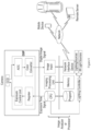
- Figure 1 schematically illustrates a plan view of an intersection of two roads 102 and 103.
- Embodiments of this invention include light sources 100 that can be positioned above (and optionally in front of) a crosswalk 104 for vertical illumination to provide illuminance E horiz , and one or more light sources 105 that can be positioned near one or both ends of the crosswalk, for example, to provide E vert components and/or light sources to provide more of a horizontal illuminance with E vert and E horiz components. These light sources may also project images as described below.
- Light sources 100 and 105 may be or comprise LED and laser light sources.
- a light source or light sources can be carried by pedestrian 106 in the form of a handheld device as shown in Figure 2 .
- the light source or sources may be for example a mobile phone or other pocket size device and/or may be worn on the pedestrian, for example on a belt or clipped on to a pocket, or worn over the shoulder, or around a neck or on bicycle such a on the handlebar, below the seat, on the peddles, wheels or spokes.
- the light sources can provide E vert illuminance on the pedestrian, and/or project an image 107 such as a crosswalk, stop, yield, or caution sign on the pavement or in a vertical location noticeable to the driver (but not for example where it would dazzle or blind a vehicle driver) such as where such a caution, yield, or stop sign may be traditionally placed.
- Such display images and text may be projected on both sides of the road where there is traffic from both directions.
- An image 107 presenting the text "stop” may have an octagonal shape on the road, for example.
- Such lighting and projection devices can be used on conventional crosswalks where additional lighting and warnings are desired as well as where a designated crosswalk is not available but a crossing must be made.
- the designated crosswalks may incorporate this technology in mounted devices that also provide E vert and E horiz illumination, can project the crosswalk image, and can project a circle or other shape around the pedestrian that follows the pedestrian(s) all the way across the street.
- the projection may also include an arrow indicating the direction of movement of the pedestrian.
- a spot light may be used instead of or in combination with this lighting that may also follow the pedestrian across the street.
- projections can include images and text on the pavement or above in locations readily visible to vehicle drivers in all relevant directions of travel, without dazzle, glare, or blinding and can be multicolor, such as white, red, yellow, green, and blue ( Figure 2 and Figure 3 ).
- Such mounted and mobile lighting systems may be used not only for crossing streets, but by pedestrians and bicycle riders as they walk or ride along the edges of street. These devices can also be used on pedestrian or sidewalks that have little or no lighting.
- These illumination systems can employ one or more detectors, sensors, or cameras that may function in the IR, ultrasonic, radar, and/or LiDAR range. Controllers and processors can take the detector, sensor, and/or camera output signals as input to output lighting control to the light source(s) and control the lighting of pixel elements in the matrix array by controlling which CMOS transistors are turned on and off, or controlling the laser beam rastering of color converting elements or pixels via a MEMS based mirror array or an acousto-optic reflector or deflector, for example.
- the road lighting system may be activated manually be a pedestrian, for example by pushing a button (not shown) on the light source support pole in Figure 4 .
- the road lighting system may alternatively be activated by a pedestrian sending a signal from a mobile device, or may automatically activate upon detecting the presence of a pedestrian.
- V2X communications may be used to provide position, speed, vehicle type and dimensions, etc. to adaptive front, rear, and side exterior lighting systems.
- GPS communications may additionally be used.
- Imaging processors can take the input of a camera, IR sensors, LiDAR, radar, ultrasound receivers and such, to map out an image of the traffic and pedestrian situation that can include location, speed, direction, etc. and send to a controller that can be optionally integrated with the processor a signal to control one or more lighting fixtures, light projections of warning images such as traffic type signs that can be multicolor and include text, as well as crosswalk projections, and pedestrian highlight, and communications to the vehicles and pedestrians.
- a spot light can illuminate a pedestrian and multiple spot lighting providing ample illuminance in the vertical plane E vert (horizontal light on the pedestrian) can be used for each pedestrian in the crossing that can emanate from a single light source such as an array or multiple light sources spatially separated can be used.
- the spot illumination need not be circular in shape and may be any shape that illuminates the pedestrian(s) and can follow the pedestrian(s) in real time. This spot illumination can be provided by light rays traveling in a direction horizontal to the pavement and normal to the vertical plane of the pedestrian and increase the vertical illuminance E vert .
- the horizontal illuminance can also follow the pedestrian(s) in real time can be any shape including for instance a rectangular section of the crossing that follows the pedestrian(s) movement.
- This E horiz illuminance can be in the form of a projection, where the area surrounding the pedestrian can be highlighted with a projection on or above the pavement, for example a partial or full circular-oval or square-rectangular type shape in white and red for example and a green arrow can be projected indicating the direction of movement.
- the horizontal illumination that is not part of the projection can be suppressed in an area around the pedestrian and the projection to maximize contrast, this suppressed or dark spot of horizontal illumination E horiz can also follow the pedestrian.
- Projections of traffic signs images that can include text and color can be projected on the ground ( Figure 2 and Figure 3 ) or above or on prelocated mounted screens that can be diffuse reflective or translucent to transmit with some scattering the projection to the opposite side that receives the projected image for viewing by the oncoming vehicles.
- displays can be used that can be programmed to change color and display a warning that is triggered when a pedestrian enters the street, this can be accomplished with one of the existing detectors and switched by the lighting controller or separate units can be used.
- the detector can also be determine the condition of the roadway, such as reflectivity, from rain and snow for example and adjust the projection accordingly for better visibility and location to allow for increased stopping distances.
- weather information may be received from an internet or Ethernet communication.
- the processor and/or controller may be connected to a network or the Ethernet that may communicate to the oncoming vehicle a visual and/or audible warning. This can be a visual warning on a dashboard display, heads-up display (HUD), or simply a warning light.
- HUD heads-up display
- the audible warning can also be from the dash display or HUD or can activate the radio speaker.
- a mobile phone or navigation device in the vehicle can be used to sound and/or display a warning.
- a warning can be communicated to a pedestrian via a mobile phone or other handheld lighting and/or communication device.
- the pedestrian's communications device may also be to communicate with the lighting system of the crosswalk to initiate a lighted crossing and receive instructions from the system on when to enter the crosswalk for example.
- An emissions source such as an infrared (IR) light source, for example a VCSEL or LED array can be used with a detector such as a camera to detect pedestrians.
- the camera and light source may be mounted in or integrated with one or more of the visible light sources 100 or 105 as shown in Figure 4 , for example, or may be mounted separately.
- signals from the camera may be processed by a processor or image analyzer and used by a lighting controller to control light sources 100 and 105 to perform as described above.
- the line schematically linking the processor or image analyzer to light source 105 indicates communication with a camera (detector) co-located with light source 105.
- one of the lines schematically linking the lighting controller to light source 105 indicates communication with an emission source used in combination with the camera (detector) co-located with light source 105.
- the camera can also detect the higher intensity white headlight beams of an oncoming vehicle as well as the lower intensity red taillights of a passing vehicle.
- the camera may comprise a CCD and digital signal processor (DSP) that communicate with each other as shown in Figure 6 , for example.
- the DSP may also communicate with the processor or an image analysis unit that can have an image input to which the DSP connects, an imaging processing unit, a CPU that can send an exposure signal back to the camera DSP, program, and memory.
- the camera DSP may further comprise an analog digital converter (ADC) that receives a CCD input, a color converter unit that outputs a digital image signal to the image input of the imaging processing unit, an exposure control unit that outputs a signal to the CCD, a register that receives an exposure signal from the CPU of the image processing unit and outputs signals to the exposure control unit and the color converter unit.
- ADC analog digital converter
- the CPU of the image analysis unit or processor can output a signal to a controller of the light sources.
- the controller can turn on and off various light sources and control the beam pattern from each of the individual light sources.
- the CPU of the image analysis unit or processor can also output a signal to a control unit of the IR light source, or the controller can operate and control all the light sources including the visible and IR.
- ultrasonic, LiDAR, radar, heat sensors that may detect IR, or pressure sensitive pads that can be installed below ground with appropriate sensors or detectors may be used along with optional supplemental sources used to generate the radiation or signal of the source to be detected.
- a portable system can be used.
- the illumination system can be carried by or worn on the pedestrian or a bicycle rider on mounted on the bicycle or other means of personal transportation such as skateboard, roller skates, or scooter.
- the portable device 120 can comprise a projector and/or illuminator, detector, computing module, and a transceiver.
- the projector/illuminator can be laser or LED based and use reflectors, lenses, and mirrors.
- the detector can include one or more sensors to detect motion and/or distance and can be for example a gyroscope, an accelerometer, GPS receiver, camera, or microphone.
- the transceiver can connect to a network or Ethernet and receive and transmit information to a remote server, a mobile device, or vehicle for example. Weather, traffic, and/or road conditions can be transmitted to the portable device from the remote server.
- Mobile devices such as mobile phones, PDAs or other like devices can transmit information about vehicles and other pedestrians to the portable device and visa-versa. Information can also be communicated directly from vehicles to the portable device of the pedestrian or bicycle rider and information about the pedestrian/bicycle rider can be transmitted back.
- the computing module can take the detector and transceiver inputs to generate appropriate illumination and/or projection display images, text messages, and colors based on these inputs.
- the computer module can also send appropriate warnings via the transceiver to mobile devices, vehicles, and remote servers through the network or Ethernet. This system is particularly useful when street crossings are made by pedestrians at non-designated mid-street and intersections and pedestrians or bicycle riders walking or riding along a dimly lit or busy street.
- the controller and processor can be integrated together in the same unit or module.
- visible and IR light source can be integrated together in the same fixture or any optional supplemental radiation source such as ultrasonic, radar, VCSEL, LED array, or LiDAR can be integrated together in a fixture. It is also possible to integrate all electronics together in the light source, so that detector radiation, detector, processor, controller as well as visible light emitting elements are together in a module or fixture that may be termed as a smart light or smart lighting source.
- the one or more light sources used in the systems described herein can provide a horizontal and vertical illuminance.
- the vertical illuminance can be less than the horizontal illuminance, the vertical illuminance can be equal the horizontal illuminance, and the vertical illuminance can be greater than the horizontal illuminance.
- the vertical illuminance be greater than the horizontal illuminance, so that the pedestrian is in positive contrast and background luminance is minimized, although the crosswalk is usually lit, so that its presence is visible.
- some variations of the systems described herein have an optional projection that can work in conjunction with the spot lighting to provide a line or boundary, partial or full around a pedestrian and/or the projection can be in the image of a traffic sign or text message. These projections can be projected on the ground or pavement and can have a local horizontal illuminance that is much higher than the surrounding horizontal illuminance.
- the horizontal illuminance of the projection can be higher than the surrounding local horizontal illuminance and approach the vertical illuminance of the pedestrian, be equal to the vertical illuminance of the pedestrian, or be greater than the vertical illuminance of the pedestrian.
- the spatial zone of the projection does not significantly overlap with the spatial zone of the vertical illuminance of the pedestrian in the view of drivers of oncoming vehicles and cause a lowering of contrast of the pedestrian or the projected image.
- the vertical illuminance is one-half or more the horizontal illuminance.
- the vertical illuminance is at least equal to the horizontal illuminance.
- the vertical illuminance is at least twice the horizontal illuminance.
- the vertical illuminance is at least five times the horizontal illuminance.
- the horizontal illuminance of the projection is at least twice the horizontal illuminance of the surroundings. In another embodiment, the horizontal illuminance of the projection is at least five times the horizontal illuminance of the surroundings. In another embodiment not corresponding to the claimed subject matter, the horizontal illuminance of the projection can be about equal to the vertical illuminance of the pedestrian. In another embodiment not corresponding to the claimed subject matter, the horizontal illuminance of the projection can be greater than the vertical illuminance of the pedestrian. In another embodiment not corresponding to the claimed subject matter, the vertical illumination of the pedestrian has minimal overlap with the horizontal illuminance of the projection in oncoming vehicles drivers' view.
- the luminance of a pedestrian is at least twice the luminance of the background or local background (outside of a projection). In another embodiment not corresponding to the claimed subject matter, the luminance of a pedestrian is at least five times the luminance of the background. In yet another embodiment not corresponding to the claimed subject matter, the luminance of a pedestrian is at least ten times the luminance of the background.
- the vertical illuminance of a pedestrian is at least 10 lx. In another embodiment, the vertical illuminance of a pedestrian is at least 20 lx. In yet another embodiment, the vertical illuminance of a pedestrian is at least 30 lx. In still another embodiment, the vertical illuminance of a pedestrian is at least 50 lx. In still yet another embodiment, the vertical illuminance of a pedestrian is at least 100 lx.
- the systems described herein may provide spot lighting or illumination of the pedestrian, where the vertical illumination of an object or pedestrian can be greater than the vertical illumination outside the spatial zone of this spot illumination.
- the spot vertical illumination is at least 1.5 times the vertical illumination outside the spot.
- the spot vertical illumination is at least twice the vertical illumination outside the spot.
- the spot vertical illumination is at least five times the vertical illumination outside the spot.
- the horizontal illumination is dimmed or turned off around the pedestrian and this dark hole follow the pedestrian, so that the vertical illumination of the spot lighting and horizontal illumination of the optional projection can be viewed with increased contrast to a vehicle driver.
- the power consumption for the road lighting systems described herein can be lower than conventional systems.
- the spot lighting of individual pedestrians in a crossing can supply excellent vertical illuminance on the pedestrian for the entire length of the crossing, without having to supply this level and uniformity of vertical illumination throughout the entire length of the crossing because the spot follows the pedestrian(s).
- the power consumption does depend on the area of illumination.
- 150 W may be consumed for a single lane street 3.5 m long with a 13500 lm metal halide bulb, can have a vertical illumination average of 85 lx with a poor uniformity of 0.6 and 500 W may be consumed for a two lane street 7 m long using two 19000 lm bulbs, can have a vertical illumination average of 180 lx with a uniformity of 0.7.
- the stationary lighting systems described herein can be turned off when pedestrians are not detected or can be dimly lit with a horizontal illuminance to make drivers aware of the crossing even though pedestrians are not present.
- the horizontal illumination can increase, so that the crosswalk is sufficiently illuminated and increased vertical illumination is provided to make the pedestrian readily visible.
- the inventive crosswalk lighting system may use less than 300 W for a two lane crossing and less than 90 W for a single lane crossing. Furthermore, such a system may use less than 200 W for a two lane crossing and less than 60 W for a single lane crossing.
- power consumption may be less and may be less dependent on the length of the crossing since vertical illumination is provided from the portable device at a nearly fixed distance to the holder and if projections are also used, they can be of a fixed length for example 4 to 10 ft. long projections of a crosswalk.
- Older designs for crosswalk lighting placed the Luminaires directly over the crosswalk. This provides high pavement illuminance E horiz , but may not adequately light the pedestrian. Newer designs move the light source at least 2 m before the cross walk relative to the direction of oncoming traffic to provide the necessary vertical illuminance (E vert ) of the pedestrian.
- E vert vertical illuminance
- a pedestrian may be represented as a cylinder 5 feet 10 inches tall, 1 foot in diameter with a reflectance of 18%.
- Refitting or retrofitting the older designs that typically use high pressure sodium or metal halide lamps with a LED array and/or laser light sources described herein may provide greatly improved pedestrian visibility without having to relocate the infrastructure.
- LED arrays and/or laser light source, detector, optional emission for the detector, processor and controller may provide for greatly improved pedestrian lighting and safety and may save on power consumption. Improved safety and energy consumption is possible whether the installation is of a new design specifically for employing this technology, a retrofit of new or old convention design, or a portable system.
- the illumination and/or projection devices used in the systems, devices, and methods described herein may be or include an LED array or laser. Some aspects of such LED arrays are further described next, with reference to Figure 8A - Figure 12 .
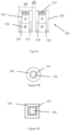
- Figure 8A and 8B show plan and schematic views of an example MxN matrix pixelated microLED 200, comprising MxN pixels 205.
- the number of individual pixels in the array can be, for example, 2 to 10 and can be used in a mobile phone flash and the like, 10 to 50 in some embodiments, 50 to 100 in some embodiments, 100 to 500 in other embodiments, 500 to 1000 in other embodiments, 1000 to 2500 in yet other embodiments, 2500 to 5000 in yet other embodiments, 5000 to 10000 in still yet other embodiments, these can be used for instance in adaptive vehicle headlights, adaptive street lights, adaptive crosswalk illumination and the like.
- Still other embodiments include 10000 to 100000 and 100000 to 500000 that can use LED or laser light sources, 500000 to 1000000, and 1000000 to 100000000 that can use laser light source or sources such as a raster scanned laser(s) may be used.
- Raster scanning may be accomplished with a microelectromechanical system (MEMS) based mirror or with an acousto-optic reflector or deflector.
- MEMS microelectromechanical system
- Figure 9A shows a partial cross sectional view of one embodiment of an LED matrix array 200.
- the n (205) and p-type (210) semiconductor layers sandwich an active region that emits light.
- the n and p-type semiconductor layers and the active region may themselves contain multiple layers of different doping levels and compositions.
- the active region may be a single light emitting layer, a homojunction, a single heterojunction, a double heterojunction or heterostructure, a single quantum well heterostructure (SQW), a multiple quantum well (MQW) structure, or a superlattice (SL) structure.
- the n and p-type semiconductor layers may be for example GaN or AlGaN and the active region may be InGaN and GaN.
- Other semiconductor material systems include AlGaInP, AlGaAs, and AlGaInAsP for example.
- the p-n junction can be passivated with a dielectric, such as SiO x , AlO x , SiON, SiAlON, TaO x , AlO x , or Si 3 N 4 or the like to prevent shorting or may be isolated by ion implantation, such as hydrogen, carbon, and oxygen ions for example.
- a dielectric such as SiO x , AlO x , SiON, SiAlON, TaO x , AlO x , or Si 3 N 4 or the like to prevent shorting or may be isolated by ion implantation, such as hydrogen, carbon, and oxygen ions for example.
- ion implantation such as hydrogen, carbon, and oxygen ions for example.
- such dielectric may be deposited on surfaces of the n and p layers in regions 220. Metal contacting the n-layer and the dielectric can extend to the p-layer side. P-metal may be deposited before or after the trench etch.
- metal contacts 240 to n-type material can extend to the p-side surface with isolation from the p-type material.
- the p-type and n-type metal electrodes may then be on the same side and can be bonded to a silicon wafer that may contain electronics such as a switching transistor, TVS, open and/or short detection and the like. Bonding can include soldering, such as AuSn or SnAgCu (SAC) solders, or a GGI bond using thermal and ultrasonic energy to form an Au bond interconnect.
- SAC SnAgCu
- the metal may be extended by plating for example past the n-layer after the growth substrate, for example sapphire, is removed.
- the n-metal can serve as the seed for plating and may be exposed by growth substrate removal, if the p-side trench and metallization extends completely through the n-layer to the substrate, by thinning the n-layer, or a subsequent trench etch from the n-side after substrate removal.
- the p and n-metal contacts are preferably reflective and may be for example Ag, Al, Ni, Ti, TiW, TiWN, Au, Zn and combinations and layers thereof.
- the extensions beyond the n-surface can be a reflective metal as described above or a TCO, such as ITO, ISO, AZO, IZO or a dielectric, such as sapphire, photoresist, SiO x , SiON, SiAlON, TaO x , AlO x , or Si 3 N 4 that may be reflective by TIR or a metallic coating.
- a TCO such as ITO, ISO, AZO, IZO
- a dielectric such as sapphire, photoresist, SiO x , SiON, SiAlON, TaO x , AlO x , or Si 3 N 4 that may be reflective by TIR or a metallic coating.
- the extensions may be used to hold or contain a wavelength converter 225, such as phosphor in silicone or other suitable binder or a ceramic phosphor.
- Phosphor may be applied by dispensing, ink-like jet printing, sedimentation, EPD, stenciling, spraying or molding.
- the pixel may be for example square, round, oval, or rectangular in shape.
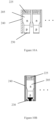
- Figure 9B and Figure 9C show that the p-electrode 230 can be square, rectangular, circular, or oval in shape surrounded by a thin dielectric 235 and the n-electrode 240 around the perimeter.
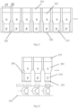
- the n-electrode may completely surround ( Figure 9A and Figure 11 ), partially surround ( Figure 10A ), or be to one side of the p-electrode ( Figure 12 ).
- the n-electrode may also overlap the p-electrode separated by a dielectric ( Figure 10B ).
- the electrodes may be connected in the device or by the Si backplane 245 (schematically shown for example in Figure 12 ) in a common cathode or anode configuration.
- the n and p-layer and electrode positions are shown in the figures for convenience, but their positions can also be swapped that is opposite from what is shown.
- Multiple matrix arrays may be used in an illumination device and these multiple arrays may be spaced apart from one another and do not have to be adjacent in an extended matrix configuration.
- one matrix in a crosswalk illumination system may provide for crosswalk illumination and another matrix is used to provide spot lighting that follows the pedestrians as they cross the street.
- Luminous efficacy can be 1 to 20 Im/W, 20 to 200 lm/W, and 200 to 500 Im/W in some embodiments.
- These arrays may be packaged with primary optics, such as lenslet arrays or compound parabolic concentrators (CPC) and may include secondary optics such as a projection lens.
- primary optics such as lenslet arrays or compound parabolic concentrators (CPC) and may include secondary optics such as a projection lens.
- CPC compound parabolic concentrators
Landscapes
- Physics & Mathematics (AREA)
- General Physics & Mathematics (AREA)
- Engineering & Computer Science (AREA)
- General Engineering & Computer Science (AREA)
- Mechanical Engineering (AREA)
- Lighting Device Outwards From Vehicle And Optical Signal (AREA)
- Traffic Control Systems (AREA)
- Circuit Arrangement For Electric Light Sources In General (AREA)
- Non-Portable Lighting Devices Or Systems Thereof (AREA)
- Road Signs Or Road Markings (AREA)
Claims (7)
- Straßenbeleuchtungssystem, eingesetzt an oder nahe einer Fahrbahn (102, 103), wobei das Straßenbeleuchtungssystem aufweist:eine oder mehrere Lichtquellen (100, 105);einen oder mehrere Detektoren, die dazu angeordnet sind, einen Fußgänger (106) an oder nahe der Fahrbahn (102, 103) zu erkennen;einen Prozessor, der dazu ausgebildet ist, Signale des einen oder der mehreren Detektoren zu verarbeiten; undeine Steuerung, die dazu ausgebildet ist, Signale von dem Prozessor zu empfangen und in Reaktion darauf, die eine oder die mehreren Lichtquellen (100, 105) zu steuern, um einen Bereich der Straßenoberfläche zu beleuchten, und dem Fußgänger eine Spot-Beleuchtung bereitzustellen, welche dem Fußgänger (106) folgt, während sich der Fußgänger (106) auf oder nahe der Fahrbahn (102, 103) bewegt, dadurch gekennzeichnet, dass die Beleuchtung des Fußgängers (106) von der einen oder den mehreren Lichtquellen (100, 105) eine vertikale Beleuchtungsstärkenkomponente in einer zu der Fahrbahn (102, 103) senkrechten Ebene und eine horizontale Komponente in einer zu der Fahrbahn (102, 103) parallelen Ebene aufweist, wobei die vertikale Beleuchtungsstärkenkomponente mindesten das Doppelte der horizontalen Beleuchtungsstärkenkomponente beträgt, wobei die Spot-Beleuchtung (108) des Fußgängers (106) einen Spot mit gedimmter oder ausgeschalteter horizontaler Beleuchtungsstärke in einer zu der Fahrbahn (102, 103) parallelen Ebene aufweist, welche erhöhten visuellen Kontrast bereitstellt und den Fußgänger (106) umgibt und diesem folgt.
- Straßenbeleuchtungssystem nach Anspruch 1, bei welchem die vertikale Beleuchtungsstärkenkomponente der Beleuchtung des Fußgängers (106) von der einen oder den mehreren Lichtquellen (100, 105) mindestens das Fünffache der horizontalen Beleuchtungsstärkenkomponente beträgt.
- Straßenbeleuchtungssystem nach Anspruch 1, bei welchemdie eine oder die mehreren Lichtquellen (100, 105) ein LED-Array (200) aufweist; unddie Steuerung dazu ausgebildet ist, Signale von dem Prozessor zu empfangen und in Reaktion darauf, Pixel (2025) in dem LED-Array zu steuern, um dem Fußgänger (106) die Spot-Beleuchtung (108) bereitzustellen, welche dem Fußgänger (106) folgt, während sich der Fußgänger (106) auf oder nahe der Fahrbahn (102, 103) bewegt.
- Straßenbeleuchtungssystem nach Anspruch 3, bei welchem
die Spot-Beleuchtung (108) des Fußgängers (106) eine Projektion (107) aufweist, welche dem Fußgänger (106) folgt und teilweise umgibt, während sich der Fußgänger (106) auf oder nahe der Fahrbahn (102, 103) bewegt. - Straßenbeleuchtungssystem nach Anspruch 4, bei welchem die Projektion (107) einen Pfeil aufweist, der die Richtung angibt, in welcher sich der Fußgänger (106) bewegt.
- Straßenbeleuchtungssystem nach Anspruch 4, bei welcher die Projektion (107) ein Verkehrsschild, eine Textnachricht, oder ein Verkehrszeichen und eine Textnachricht aufweist, welche für einen sich dem Fußgänger nähernden Fahrzeugführer sichtbar sind.
- Straßenbeleuchtungssystem nach Anspruch 4, bei welchem die horizontale Beleuchtungsstärke der Projektion (107) in einer zu der Fahrbahn (102, 103) parallelen Ebene mindestens das Doppelte der horizontalen Beleuchtungsstärke der umgebenden Fahrbahn (102, 103) beträgt.
Applications Claiming Priority (6)
| Application Number | Priority Date | Filing Date | Title |
|---|---|---|---|
| US201762608963P | 2017-12-21 | 2017-12-21 | |
| EP18163162 | 2018-03-21 | ||
| US16/228,516 US11107346B2 (en) | 2017-12-21 | 2018-12-20 | Road lighting |
| US16/228,514 US10885772B2 (en) | 2017-12-21 | 2018-12-20 | Road lighting |
| US16/228,506 US10957187B2 (en) | 2017-12-21 | 2018-12-20 | Road lighting |
| PCT/US2018/067132 WO2019126663A2 (en) | 2017-12-21 | 2018-12-21 | Road lighting |
Publications (2)
| Publication Number | Publication Date |
|---|---|
| EP3729403A2 EP3729403A2 (de) | 2020-10-28 |
| EP3729403B1 true EP3729403B1 (de) | 2025-04-02 |
Family
ID=66950534
Family Applications (1)
| Application Number | Title | Priority Date | Filing Date |
|---|---|---|---|
| EP18830995.9A Active EP3729403B1 (de) | 2017-12-21 | 2018-12-21 | Strassenbeleuchtung |
Country Status (7)
| Country | Link |
|---|---|
| US (6) | US10885772B2 (de) |
| EP (1) | EP3729403B1 (de) |
| JP (1) | JP7305649B2 (de) |
| KR (1) | KR102729211B1 (de) |
| CN (2) | CN115802565B (de) |
| TW (1) | TWI816725B (de) |
| WO (1) | WO2019126663A2 (de) |
Families Citing this family (44)
| Publication number | Priority date | Publication date | Assignee | Title |
|---|---|---|---|---|
| US10885772B2 (en) | 2017-12-21 | 2021-01-05 | Lumileds Llc | Road lighting |
| CN110097768B (zh) * | 2018-01-30 | 2021-12-21 | 西门子公司 | 交通信号指示方法、装置、系统和机器可读介质 |
| US11798406B2 (en) | 2018-03-21 | 2023-10-24 | Lumileds Llc | Road lighting |
| US11281084B2 (en) | 2018-07-18 | 2022-03-22 | Optonomous Technologies, Inc. | Illumination system with crystal phosphor mechanism and method of operation thereof |
| DE102018008213B4 (de) * | 2018-10-17 | 2024-02-29 | Mercedes-Benz Group AG | Verfahren zum Visualisieren eines Übergangs über eine Straße |
| US11480854B2 (en) * | 2018-12-26 | 2022-10-25 | Lumileds Llc | Vehicle side and rear exterior illumination and projection |
| US11004342B2 (en) * | 2019-06-04 | 2021-05-11 | Dick Campbell Company | Turn lane pedestrian indicator |
| JPWO2020251034A1 (de) * | 2019-06-13 | 2020-12-17 | ||
| DE102019120275A1 (de) * | 2019-07-26 | 2021-01-28 | Siteco Gmbh | Strassenleuchte mit kommunikationsschnittstelle zu fahrzeugen |
| IT201900017174A1 (it) * | 2019-09-25 | 2021-03-25 | Puda Soc Coop A R L | Sistema di sicurezza per attraversamenti pedonali |
| CN111145534A (zh) * | 2019-12-30 | 2020-05-12 | 深圳市综合交通设计研究院有限公司 | 道路交叉口安全岛交通疏导方法和系统 |
| US11610482B2 (en) * | 2020-03-16 | 2023-03-21 | Vihaan Gaurav | System to warn a motorist of the presence of a pedestrian in a crosswalk at a traffic intersection |
| CA3113473A1 (en) * | 2020-03-24 | 2021-09-24 | Arudi Srinivas Rajagopal | Traffic warning and data capture devices and methods |
| US10821938B1 (en) * | 2020-05-01 | 2020-11-03 | Moj.Io, Inc. | Compute system with theft alert mechanism and method of operation thereof |
| US11926344B1 (en) * | 2020-05-03 | 2024-03-12 | Matthew MacGregor Roy | Autonomous vehicle having light projector for illuminating ground under pedestrians and cyclists |
| KR102829342B1 (ko) * | 2020-05-08 | 2025-07-02 | 현대자동차주식회사 | 차량의 커뮤니케이션 조명 시스템 |
| US11790770B2 (en) * | 2020-07-02 | 2023-10-17 | On It Solutions, LLC | Illumination system for crossing zone |
| US11320104B1 (en) * | 2020-07-29 | 2022-05-03 | Kendall Perkins | Solar-powered light for motorists on roadways |
| US12146643B2 (en) * | 2020-12-21 | 2024-11-19 | Intel Corporation | Dynamically adjusting an infrastructure item |
| CN112738961B (zh) * | 2021-01-06 | 2023-04-18 | 苏州鱼得水电气科技有限公司 | 一种基于大数据的智能化道路照明用控制系统 |
| CN112483968A (zh) * | 2021-01-26 | 2021-03-12 | 深圳市帕特商贸有限公司 | 一种带夜间行人检测与提醒功能的路灯 |
| CN112921851B (zh) * | 2021-02-01 | 2022-06-10 | 武汉理工大学 | 一种自解释性的路中行人过街交通安全设施 |
| GB202102542D0 (en) * | 2021-02-23 | 2021-04-07 | Raynestorm Ltd | Hospitality smart system |
| TWI767646B (zh) * | 2021-04-06 | 2022-06-11 | 晶亮電工股份有限公司 | 行人智慧照明系統及其控制方法 |
| SK9419Y1 (sk) * | 2021-04-07 | 2022-01-26 | MVDr. Kovalovský Filip | Systém osvetlenia priechodov, najmä priechodov pre chodcov |
| EP4084580A1 (de) | 2021-04-30 | 2022-11-02 | Koninklijke Philips N.V. | Lichtausgabesystem und entwurfsverfahren |
| TWI752892B (zh) * | 2021-06-28 | 2022-01-11 | 晶亮電工股份有限公司 | 行人穿越道照明裝置 |
| US11741831B2 (en) * | 2021-11-30 | 2023-08-29 | Automotive Research & Testing Center | Intersection warning system based on information fusion and method thereof |
| US12543410B2 (en) * | 2021-12-14 | 2026-02-03 | Lumileds Singapore Pte. Ltd. | Light-collecting structures for a light-emitting array |
| US20230215274A1 (en) * | 2021-12-30 | 2023-07-06 | Gevin Joseph McDaniel | Intersection right-turn pedestrian alert system |
| US20250232592A1 (en) * | 2022-04-08 | 2025-07-17 | Sumitomo Electric Industries, Ltd. | Detection system, detection device, and method of installing detection device |
| JP7805632B2 (ja) * | 2022-05-24 | 2026-01-26 | 株式会社因幡電機製作所 | 死角表示装置 |
| TWI876420B (zh) * | 2022-07-18 | 2025-03-11 | 禾伸堂企業股份有限公司 | 多物件影像追蹤投射燈矩陣 |
| CN115162225B (zh) * | 2022-09-06 | 2022-11-22 | 南京智慧交通信息股份有限公司 | 一种基于智慧交通具有行人保护功能的智能警示系统 |
| TWI811157B (zh) * | 2022-11-17 | 2023-08-01 | 英田科技有限公司 | 具有雷射功能之照明裝置及具有該照明裝置的照明系統 |
| JP7822920B2 (ja) * | 2022-12-13 | 2026-03-03 | ダイムラー トラック エージー | 自動運転車両の制御システム |
| JP7768151B2 (ja) * | 2023-01-04 | 2025-11-12 | トヨタ自動車株式会社 | 移動体の移動支援方法及び移動支援システム |
| JP7775843B2 (ja) * | 2023-01-04 | 2025-11-26 | トヨタ自動車株式会社 | 移動体の移動支援方法及び移動支援システム |
| US20240280230A1 (en) * | 2023-02-17 | 2024-08-22 | Polara Enterprises, Llc | Overhead crosswalk lighting arrangement |
| US20240331543A1 (en) * | 2023-03-27 | 2024-10-03 | Ryan Leo Groszmann | Pedestrian crosswalk alert system |
| DE102024114305A1 (de) | 2023-05-25 | 2024-11-28 | Nichia Corporation | Lichtausstrahlungsvorrichtung und verkehrssystem |
| KR20250026542A (ko) * | 2023-08-17 | 2025-02-25 | 현대모비스 주식회사 | 차량용 정보표시 장치 및 이를 이용한 정보표시 방법 |
| TWI852758B (zh) * | 2023-09-07 | 2024-08-11 | 晶亮電工股份有限公司 | 用於照明行人穿越道的照明裝置 |
| CN119545623B (zh) * | 2024-11-29 | 2025-11-28 | 中栩建设工程集团有限公司 | 一种基于人工智能的路灯照明智能控制系统及方法 |
Family Cites Families (70)
| Publication number | Priority date | Publication date | Assignee | Title |
|---|---|---|---|---|
| FR13733E (fr) | 1910-09-19 | 1911-06-17 | Amandus Bartels | Procédé de préparation d'une matière analogue à la corne |
| DE305641C (de) | 1917-04-25 | 1919-05-21 | ||
| FR32611E (fr) | 1926-12-08 | 1928-02-14 | Entpr Et D Expl Ateliers D Arl | épurateur électrique |
| FR59178E (fr) | 1949-04-11 | 1954-05-06 | Procédé de fabrication des têtes d'arrêt des câbles de freins de bicyclettes etautres véhicules | |
| IL120175A (en) * | 1997-02-07 | 2000-11-21 | Tribelsky Zamir | Method for optically marking an elongated indication path and devices using this method |
| US6692245B1 (en) * | 1997-08-18 | 2004-02-17 | Ipl Inc. | Mold for making a window frame |
| JP2001338778A (ja) * | 2000-05-30 | 2001-12-07 | Matsushita Electric Works Ltd | 照明装置 |
| JP2003217869A (ja) * | 2002-01-28 | 2003-07-31 | Matsushita Electric Works Ltd | 照明装置 |
| US9955551B2 (en) * | 2002-07-12 | 2018-04-24 | Yechezkal Evan Spero | Detector controlled illuminating system |
| FR2850616B1 (fr) * | 2003-01-30 | 2006-02-17 | Valeo Vision | Procede d'eclairage module d'une route et projecteur de vehicule mettant en oeuvre ce procede |
| EP1623399A2 (de) * | 2003-05-07 | 2006-02-08 | Koninklijke Philips Electronics N.V. | Öffentliches dienstsystem |
| JP5262057B2 (ja) | 2006-11-17 | 2013-08-14 | 株式会社豊田中央研究所 | 照射装置 |
| CN201311671Y (zh) * | 2008-11-07 | 2009-09-16 | 永泰软件有限公司 | 基于步态模式追踪的多人检测算法的防尾随通道 |
| ES2321794B2 (es) * | 2009-03-13 | 2009-11-20 | Javier F. Dominguez Diez | Paso de peatones elevado con señalizacion luminosa. |
| KR101576623B1 (ko) | 2009-03-27 | 2015-12-10 | 주식회사 아모센스 | 엘이디 조명 장치 |
| US8517566B2 (en) * | 2009-09-25 | 2013-08-27 | Musco Corporation | Apparatus, method, and system for roadway lighting using solid-state light sources |
| DE102009057219B4 (de) * | 2009-10-24 | 2023-07-20 | Mercedes-Benz Group AG | Vorrichtung zur Steuerung eines Fahrlichts eines Fahrzeugs |
| JP2011175560A (ja) * | 2010-02-25 | 2011-09-08 | Tsumura Sogo Kenkyusho:Kk | 衝突防止装置 |
| TW201220952A (en) * | 2010-03-29 | 2012-05-16 | Koninkl Philips Electronics Nv | Network of heterogeneous devices including at least one outdoor lighting fixture node |
| JP2012028272A (ja) * | 2010-07-27 | 2012-02-09 | Panasonic Electric Works Co Ltd | 照明装置 |
| US9230419B2 (en) | 2010-07-27 | 2016-01-05 | Rite-Hite Holding Corporation | Methods and apparatus to detect and warn proximate entities of interest |
| US8651714B1 (en) | 2010-09-20 | 2014-02-18 | Noriaki Hamasaki | Portable lighting device |
| JP5083397B2 (ja) | 2010-09-29 | 2012-11-28 | 株式会社デンソー | 路車協調照明システム |
| KR20120042209A (ko) * | 2010-10-25 | 2012-05-03 | 주식회사 서연네트웍스 | 야간 횡단보도용 가로등 |
| WO2012116191A1 (en) * | 2011-02-23 | 2012-08-30 | Eve Biomedical, Inc. | Rotation-dependent transcriptional sequencing systems and methods of using |
| JP6057543B2 (ja) | 2011-05-23 | 2017-01-11 | エルジー イノテック カンパニー リミテッド | 照明装置 |
| CN103175080A (zh) * | 2011-12-23 | 2013-06-26 | 海洋王(东莞)照明科技有限公司 | 一种交通辅助装置 |
| US9057926B1 (en) * | 2012-01-27 | 2015-06-16 | Rockwell Collins, Inc. | Multi-wavelength emitter array |
| DE102012206691A1 (de) | 2012-04-24 | 2013-10-24 | Zumtobel Lighting Gmbh | Straßen- und Wegbeleuchtungssystem |
| WO2014007452A1 (ko) | 2012-07-02 | 2014-01-09 | 순천대학교 산학협력단 | 조명 장치 및 조명 방법 |
| GB2504334A (en) * | 2012-07-26 | 2014-01-29 | Sharp Kk | Headlight system with adaptive beams |
| JP5696701B2 (ja) * | 2012-08-31 | 2015-04-08 | 株式会社デンソー | 対歩行者報知装置 |
| CN102798065B (zh) * | 2012-09-11 | 2015-03-25 | 深圳大学 | 一种低灯位多维道路照明方法 |
| EP2896875B1 (de) | 2012-09-11 | 2019-05-22 | Shenzhen University | Mehrdimensionales strassenbeleuchtungssystem |
| WO2014109885A2 (en) * | 2013-01-09 | 2014-07-17 | Lsi Industries, Inc. | Lighting system control and synthetic event generation |
| CN103993563B (zh) * | 2013-02-20 | 2016-06-08 | 深圳市海洋王照明工程有限公司 | 斑马线信号装置 |
| JP5790698B2 (ja) | 2013-04-11 | 2015-10-07 | トヨタ自動車株式会社 | 情報表示装置、及び情報表示方法 |
| US9338850B2 (en) * | 2013-04-24 | 2016-05-10 | GE Lighting Solutions, LLC | Lighting systems and methods providing active glare control |
| RU2541591C1 (ru) * | 2013-10-03 | 2015-02-20 | Общество с ограниченной ответственностью "Научно-производственное объединение "ЯВИР" | Автономный комплекс обустройства пешеходного перехода с телеметрией на основе gsm/gprs модуля |
| TWI511612B (zh) | 2013-12-13 | 2015-12-01 | Lite On Technology Corp | 適用於路燈之環境偵測裝置及其環境偵測方法 |
| TW201531164A (zh) * | 2013-12-20 | 2015-08-01 | Sensity Systems Inc | 使用複合照明模型之動態空間分辨照明 |
| CN103770733B (zh) * | 2014-01-15 | 2017-01-11 | 中国人民解放军国防科学技术大学 | 一种驾驶员安全驾驶状态检测方法及装置 |
| US20170038018A1 (en) | 2014-04-15 | 2017-02-09 | 3M Innovative Properties Company | Control of bollard luminaire for crosswalk |
| EP3140214B1 (de) | 2014-05-05 | 2018-08-29 | WestRock Packaging Systems, LLC | Paneelverzahnungsvorrichtung für einen karton und zuschnitt dafür |
| US9831387B2 (en) * | 2014-06-14 | 2017-11-28 | Hiphoton Co., Ltd. | Light engine array |
| US20170182934A1 (en) | 2014-09-01 | 2017-06-29 | Mitsubishi Electric Corporation | Vehicle projection control system and method of controlling image projection |
| CN105467935A (zh) * | 2014-09-03 | 2016-04-06 | 秦皇岛中科百捷电子信息科技有限公司 | 一种建筑主动式节能监控系统及方法 |
| JP6746270B2 (ja) * | 2014-09-08 | 2020-08-26 | 株式会社小糸製作所 | 車両用表示システム |
| JP2016090318A (ja) | 2014-10-31 | 2016-05-23 | 株式会社日本自動車部品総合研究所 | 投影端末 |
| TWI575185B (zh) * | 2015-03-25 | 2017-03-21 | Intelligent lighting device for vehicle (2) | |
| CN104822196B (zh) * | 2015-04-15 | 2017-09-08 | 常州大学 | 一种基于视觉技术的路灯亮度自动调节系统 |
| CN204623641U (zh) * | 2015-05-13 | 2015-09-09 | 纳恩博(北京)科技有限公司 | 多向发光的行驶状态指示装置 |
| KR101628906B1 (ko) * | 2015-07-30 | 2016-06-09 | (주)미주 | 횡단보도 자동 조명 제어 장치 및 방법 |
| CN204945799U (zh) * | 2015-09-18 | 2016-01-06 | 天津鑫隆机场设备有限公司 | 基于路标线识别技术的助航灯光强检测车视频引导装置 |
| DE102015225410A1 (de) | 2015-12-16 | 2017-06-22 | Bayerische Motoren Werke Aktiengesellschaft | Verfahren und Steuereinheit zur Vermeidung von Gefahrensituation im Straßenverkehr |
| KR101655730B1 (ko) * | 2016-03-04 | 2016-09-08 | 주식회사 드림인테크 | 빔프로젝터를 구비한 스마트형 교통안전시스템 |
| CN105761526A (zh) * | 2016-03-06 | 2016-07-13 | 汪学林 | 一种交通信号灯 |
| CN105889882B (zh) * | 2016-06-06 | 2019-01-29 | 中国计量大学 | 一种道路路灯控制方法 |
| CN205844717U (zh) * | 2016-06-27 | 2016-12-28 | 淮安天宇智联科技有限公司 | 一种智能化摄影灯 |
| CN205919225U (zh) * | 2016-08-28 | 2017-02-01 | 郭新溢 | 一种智能夜灯 |
| KR101728080B1 (ko) * | 2016-09-13 | 2017-04-18 | 주식회사 우주씨앤티 | 도로 교통사고 예방장치 |
| CN106594581A (zh) * | 2016-10-27 | 2017-04-26 | 浙江工商职业技术学院 | 一种可自动跟随的照明灯具 |
| JP2018110057A (ja) | 2016-12-28 | 2018-07-12 | パナソニックIpマネジメント株式会社 | 照明システム、照明方法及びプログラム |
| KR101739988B1 (ko) * | 2017-02-09 | 2017-05-26 | (주)패스넷 | 무신호 횡단보도에서의 보행자 보호 시스템 |
| CN106900108B (zh) * | 2017-02-28 | 2018-10-26 | 横店集团得邦照明股份有限公司 | 一种自组织led场景灯 |
| JP6465317B2 (ja) | 2017-03-10 | 2019-02-06 | 株式会社Subaru | 画像表示装置 |
| US10893400B2 (en) * | 2017-03-10 | 2021-01-12 | Blackberry Limited | Pedestrian safety communication system and method |
| CN107085964B (zh) * | 2017-05-10 | 2018-10-26 | 深圳市夏瑞科技有限公司 | 基于图像增强的车辆自动驾驶系统 |
| CN107139836A (zh) * | 2017-06-29 | 2017-09-08 | 成都大学 | 一种大型客货车智能安全报警装置及方法 |
| US10885772B2 (en) | 2017-12-21 | 2021-01-05 | Lumileds Llc | Road lighting |
-
2018
- 2018-12-20 US US16/228,514 patent/US10885772B2/en active Active
- 2018-12-20 US US16/228,506 patent/US10957187B2/en active Active
- 2018-12-20 US US16/228,516 patent/US11107346B2/en active Active
- 2018-12-21 KR KR1020207021034A patent/KR102729211B1/ko active Active
- 2018-12-21 TW TW107146570A patent/TWI816725B/zh active
- 2018-12-21 WO PCT/US2018/067132 patent/WO2019126663A2/en not_active Ceased
- 2018-12-21 CN CN202211630530.5A patent/CN115802565B/zh active Active
- 2018-12-21 EP EP18830995.9A patent/EP3729403B1/de active Active
- 2018-12-21 CN CN201880090062.2A patent/CN111712864B/zh active Active
- 2018-12-21 JP JP2020534970A patent/JP7305649B2/ja active Active
-
2021
- 2021-08-19 US US17/407,019 patent/US11508235B2/en active Active
-
2022
- 2022-11-21 US US17/991,364 patent/US11798405B2/en active Active
- 2022-12-19 US US18/084,369 patent/US11854384B2/en active Active
Also Published As
| Publication number | Publication date |
|---|---|
| US11798405B2 (en) | 2023-10-24 |
| CN115802565A (zh) | 2023-03-14 |
| US20190197883A1 (en) | 2019-06-27 |
| US10885772B2 (en) | 2021-01-05 |
| US20230120794A1 (en) | 2023-04-20 |
| WO2019126663A2 (en) | 2019-06-27 |
| JP7305649B2 (ja) | 2023-07-10 |
| JP2021507420A (ja) | 2021-02-22 |
| WO2019126663A3 (en) | 2019-08-08 |
| US20190197882A1 (en) | 2019-06-27 |
| KR102729211B1 (ko) | 2024-11-13 |
| US11107346B2 (en) | 2021-08-31 |
| US20230110272A1 (en) | 2023-04-13 |
| US20210383683A1 (en) | 2021-12-09 |
| US20190197881A1 (en) | 2019-06-27 |
| CN111712864B (zh) | 2023-01-03 |
| TWI816725B (zh) | 2023-10-01 |
| TW201936010A (zh) | 2019-09-01 |
| US10957187B2 (en) | 2021-03-23 |
| KR20200103050A (ko) | 2020-09-01 |
| CN111712864A (zh) | 2020-09-25 |
| US11508235B2 (en) | 2022-11-22 |
| CN115802565B (zh) | 2025-08-08 |
| US11854384B2 (en) | 2023-12-26 |
| EP3729403A2 (de) | 2020-10-28 |
Similar Documents
| Publication | Publication Date | Title |
|---|---|---|
| US11798405B2 (en) | Road lighting | |
| US11798406B2 (en) | Road lighting | |
| US12360444B2 (en) | Vehicle side and rear exterior illumination and projection | |
| CN108859933B (zh) | 车辆用灯泡及车辆 | |
| US11465553B2 (en) | Illuminating lamp for vehicle | |
| US11772545B2 (en) | Apparatus, system and method for controlling lighting using gated imaging | |
| US10493902B2 (en) | Vehicle lighting system | |
| CN110966563B (zh) | 车辆用前照灯 | |
| US10730427B2 (en) | Lighting device | |
| CN104768313A (zh) | 一种用于车辆前照灯的智能控制系统 | |
| JP7370805B2 (ja) | 車両の路面描画装置。 | |
| CN111765433A (zh) | 车灯探测投影系统及其操作方法 |
Legal Events
| Date | Code | Title | Description |
|---|---|---|---|
| STAA | Information on the status of an ep patent application or granted ep patent |
Free format text: STATUS: UNKNOWN |
|
| STAA | Information on the status of an ep patent application or granted ep patent |
Free format text: STATUS: THE INTERNATIONAL PUBLICATION HAS BEEN MADE |
|
| PUAI | Public reference made under article 153(3) epc to a published international application that has entered the european phase |
Free format text: ORIGINAL CODE: 0009012 |
|
| STAA | Information on the status of an ep patent application or granted ep patent |
Free format text: STATUS: REQUEST FOR EXAMINATION WAS MADE |
|
| 17P | Request for examination filed |
Effective date: 20200721 |
|
| AK | Designated contracting states |
Kind code of ref document: A2 Designated state(s): AL AT BE BG CH CY CZ DE DK EE ES FI FR GB GR HR HU IE IS IT LI LT LU LV MC MK MT NL NO PL PT RO RS SE SI SK SM TR |
|
| AX | Request for extension of the european patent |
Extension state: BA ME |
|
| DAV | Request for validation of the european patent (deleted) | ||
| DAX | Request for extension of the european patent (deleted) | ||
| STAA | Information on the status of an ep patent application or granted ep patent |
Free format text: STATUS: EXAMINATION IS IN PROGRESS |
|
| 17Q | First examination report despatched |
Effective date: 20210915 |
|
| GRAP | Despatch of communication of intention to grant a patent |
Free format text: ORIGINAL CODE: EPIDOSNIGR1 |
|
| STAA | Information on the status of an ep patent application or granted ep patent |
Free format text: STATUS: GRANT OF PATENT IS INTENDED |
|
| INTG | Intention to grant announced |
Effective date: 20241021 |
|
| P01 | Opt-out of the competence of the unified patent court (upc) registered |
Free format text: CASE NUMBER: APP_62858/2024 Effective date: 20241126 |
|
| GRAS | Grant fee paid |
Free format text: ORIGINAL CODE: EPIDOSNIGR3 |
|
| GRAA | (expected) grant |
Free format text: ORIGINAL CODE: 0009210 |
|
| STAA | Information on the status of an ep patent application or granted ep patent |
Free format text: STATUS: THE PATENT HAS BEEN GRANTED |
|
| AK | Designated contracting states |
Kind code of ref document: B1 Designated state(s): AL AT BE BG CH CY CZ DE DK EE ES FI FR GB GR HR HU IE IS IT LI LT LU LV MC MK MT NL NO PL PT RO RS SE SI SK SM TR |
|
| REG | Reference to a national code |
Ref country code: GB Ref legal event code: FG4D |
|
| REG | Reference to a national code |
Ref country code: CH Ref legal event code: EP |
|
| REG | Reference to a national code |
Ref country code: IE Ref legal event code: FG4D |
|
| REG | Reference to a national code |
Ref country code: DE Ref legal event code: R096 Ref document number: 602018080770 Country of ref document: DE |
|
| REG | Reference to a national code |
Ref country code: NL Ref legal event code: MP Effective date: 20250402 |
|
| PG25 | Lapsed in a contracting state [announced via postgrant information from national office to epo] |
Ref country code: NL Free format text: LAPSE BECAUSE OF FAILURE TO SUBMIT A TRANSLATION OF THE DESCRIPTION OR TO PAY THE FEE WITHIN THE PRESCRIBED TIME-LIMIT Effective date: 20250402 |
|
| REG | Reference to a national code |
Ref country code: AT Ref legal event code: MK05 Ref document number: 1782087 Country of ref document: AT Kind code of ref document: T Effective date: 20250402 |
|
| PG25 | Lapsed in a contracting state [announced via postgrant information from national office to epo] |
Ref country code: FI Free format text: LAPSE BECAUSE OF FAILURE TO SUBMIT A TRANSLATION OF THE DESCRIPTION OR TO PAY THE FEE WITHIN THE PRESCRIBED TIME-LIMIT Effective date: 20250402 Ref country code: PT Free format text: LAPSE BECAUSE OF FAILURE TO SUBMIT A TRANSLATION OF THE DESCRIPTION OR TO PAY THE FEE WITHIN THE PRESCRIBED TIME-LIMIT Effective date: 20250804 Ref country code: ES Free format text: LAPSE BECAUSE OF FAILURE TO SUBMIT A TRANSLATION OF THE DESCRIPTION OR TO PAY THE FEE WITHIN THE PRESCRIBED TIME-LIMIT Effective date: 20250402 |
|
| REG | Reference to a national code |
Ref country code: LT Ref legal event code: MG9D |
|
| PG25 | Lapsed in a contracting state [announced via postgrant information from national office to epo] |
Ref country code: NO Free format text: LAPSE BECAUSE OF FAILURE TO SUBMIT A TRANSLATION OF THE DESCRIPTION OR TO PAY THE FEE WITHIN THE PRESCRIBED TIME-LIMIT Effective date: 20250702 Ref country code: GR Free format text: LAPSE BECAUSE OF FAILURE TO SUBMIT A TRANSLATION OF THE DESCRIPTION OR TO PAY THE FEE WITHIN THE PRESCRIBED TIME-LIMIT Effective date: 20250703 |
|
| PG25 | Lapsed in a contracting state [announced via postgrant information from national office to epo] |
Ref country code: PL Free format text: LAPSE BECAUSE OF FAILURE TO SUBMIT A TRANSLATION OF THE DESCRIPTION OR TO PAY THE FEE WITHIN THE PRESCRIBED TIME-LIMIT Effective date: 20250402 |
|
| PG25 | Lapsed in a contracting state [announced via postgrant information from national office to epo] |
Ref country code: BG Free format text: LAPSE BECAUSE OF FAILURE TO SUBMIT A TRANSLATION OF THE DESCRIPTION OR TO PAY THE FEE WITHIN THE PRESCRIBED TIME-LIMIT Effective date: 20250402 |
|
| PG25 | Lapsed in a contracting state [announced via postgrant information from national office to epo] |
Ref country code: HR Free format text: LAPSE BECAUSE OF FAILURE TO SUBMIT A TRANSLATION OF THE DESCRIPTION OR TO PAY THE FEE WITHIN THE PRESCRIBED TIME-LIMIT Effective date: 20250402 |
|
| PG25 | Lapsed in a contracting state [announced via postgrant information from national office to epo] |
Ref country code: AT Free format text: LAPSE BECAUSE OF FAILURE TO SUBMIT A TRANSLATION OF THE DESCRIPTION OR TO PAY THE FEE WITHIN THE PRESCRIBED TIME-LIMIT Effective date: 20250402 |
|
| PG25 | Lapsed in a contracting state [announced via postgrant information from national office to epo] |
Ref country code: RS Free format text: LAPSE BECAUSE OF FAILURE TO SUBMIT A TRANSLATION OF THE DESCRIPTION OR TO PAY THE FEE WITHIN THE PRESCRIBED TIME-LIMIT Effective date: 20250702 |
|
| PG25 | Lapsed in a contracting state [announced via postgrant information from national office to epo] |
Ref country code: IS Free format text: LAPSE BECAUSE OF FAILURE TO SUBMIT A TRANSLATION OF THE DESCRIPTION OR TO PAY THE FEE WITHIN THE PRESCRIBED TIME-LIMIT Effective date: 20250802 |
|
| PG25 | Lapsed in a contracting state [announced via postgrant information from national office to epo] |
Ref country code: LV Free format text: LAPSE BECAUSE OF FAILURE TO SUBMIT A TRANSLATION OF THE DESCRIPTION OR TO PAY THE FEE WITHIN THE PRESCRIBED TIME-LIMIT Effective date: 20250402 |
|
| REG | Reference to a national code |
Ref country code: DE Ref legal event code: R097 Ref document number: 602018080770 Country of ref document: DE |
|
| PGFP | Annual fee paid to national office [announced via postgrant information from national office to epo] |
Ref country code: GB Payment date: 20251223 Year of fee payment: 8 |
|
| PG25 | Lapsed in a contracting state [announced via postgrant information from national office to epo] |
Ref country code: SM Free format text: LAPSE BECAUSE OF FAILURE TO SUBMIT A TRANSLATION OF THE DESCRIPTION OR TO PAY THE FEE WITHIN THE PRESCRIBED TIME-LIMIT Effective date: 20250402 Ref country code: DK Free format text: LAPSE BECAUSE OF FAILURE TO SUBMIT A TRANSLATION OF THE DESCRIPTION OR TO PAY THE FEE WITHIN THE PRESCRIBED TIME-LIMIT Effective date: 20250402 |
|
| PGFP | Annual fee paid to national office [announced via postgrant information from national office to epo] |
Ref country code: FR Payment date: 20251230 Year of fee payment: 8 |
|
| PG25 | Lapsed in a contracting state [announced via postgrant information from national office to epo] |
Ref country code: CZ Free format text: LAPSE BECAUSE OF FAILURE TO SUBMIT A TRANSLATION OF THE DESCRIPTION OR TO PAY THE FEE WITHIN THE PRESCRIBED TIME-LIMIT Effective date: 20250402 |
|
| PG25 | Lapsed in a contracting state [announced via postgrant information from national office to epo] |
Ref country code: EE Free format text: LAPSE BECAUSE OF FAILURE TO SUBMIT A TRANSLATION OF THE DESCRIPTION OR TO PAY THE FEE WITHIN THE PRESCRIBED TIME-LIMIT Effective date: 20250402 |
|
| PG25 | Lapsed in a contracting state [announced via postgrant information from national office to epo] |
Ref country code: RO Free format text: LAPSE BECAUSE OF FAILURE TO SUBMIT A TRANSLATION OF THE DESCRIPTION OR TO PAY THE FEE WITHIN THE PRESCRIBED TIME-LIMIT Effective date: 20250402 Ref country code: SK Free format text: LAPSE BECAUSE OF FAILURE TO SUBMIT A TRANSLATION OF THE DESCRIPTION OR TO PAY THE FEE WITHIN THE PRESCRIBED TIME-LIMIT Effective date: 20250402 |
|
| PG25 | Lapsed in a contracting state [announced via postgrant information from national office to epo] |
Ref country code: IT Free format text: LAPSE BECAUSE OF FAILURE TO SUBMIT A TRANSLATION OF THE DESCRIPTION OR TO PAY THE FEE WITHIN THE PRESCRIBED TIME-LIMIT Effective date: 20250402 |
|
| PLBE | No opposition filed within time limit |
Free format text: ORIGINAL CODE: 0009261 |
|
| STAA | Information on the status of an ep patent application or granted ep patent |
Free format text: STATUS: NO OPPOSITION FILED WITHIN TIME LIMIT |
|
| REG | Reference to a national code |
Ref country code: CH Ref legal event code: L10 Free format text: ST27 STATUS EVENT CODE: U-0-0-L10-L00 (AS PROVIDED BY THE NATIONAL OFFICE) Effective date: 20260211 |
|
| 26N | No opposition filed |
Effective date: 20260105 |
|
| PGFP | Annual fee paid to national office [announced via postgrant information from national office to epo] |
Ref country code: DE Payment date: 20251229 Year of fee payment: 8 |