EP3728060B1 - Dosierventil für ein produkt - Google Patents
Dosierventil für ein produkt Download PDFInfo
- Publication number
- EP3728060B1 EP3728060B1 EP18891920.3A EP18891920A EP3728060B1 EP 3728060 B1 EP3728060 B1 EP 3728060B1 EP 18891920 A EP18891920 A EP 18891920A EP 3728060 B1 EP3728060 B1 EP 3728060B1
- Authority
- EP
- European Patent Office
- Prior art keywords
- valve
- stem
- metered
- product
- cylindrical body
- Prior art date
- Legal status (The legal status is an assumption and is not a legal conclusion. Google has not performed a legal analysis and makes no representation as to the accuracy of the status listed.)
- Active
Links
- 125000006850 spacer group Chemical group 0.000 claims description 40
- 239000012530 fluid Substances 0.000 claims description 11
- 238000004891 communication Methods 0.000 claims description 6
- 238000007789 sealing Methods 0.000 claims description 4
- 230000000694 effects Effects 0.000 claims description 3
- 238000005429 filling process Methods 0.000 description 8
- 239000007921 spray Substances 0.000 description 8
- 238000004519 manufacturing process Methods 0.000 description 5
- 238000000034 method Methods 0.000 description 5
- 230000007246 mechanism Effects 0.000 description 3
- 239000003380 propellant Substances 0.000 description 3
- 230000009471 action Effects 0.000 description 2
- 239000000443 aerosol Substances 0.000 description 2
- 230000004888 barrier function Effects 0.000 description 2
- 230000006835 compression Effects 0.000 description 2
- 238000007906 compression Methods 0.000 description 2
- 239000007788 liquid Substances 0.000 description 2
- 239000000463 material Substances 0.000 description 2
- NJPPVKZQTLUDBO-UHFFFAOYSA-N novaluron Chemical compound C1=C(Cl)C(OC(F)(F)C(OC(F)(F)F)F)=CC=C1NC(=O)NC(=O)C1=C(F)C=CC=C1F NJPPVKZQTLUDBO-UHFFFAOYSA-N 0.000 description 2
- 230000004913 activation Effects 0.000 description 1
- 239000004479 aerosol dispenser Substances 0.000 description 1
- 230000007423 decrease Effects 0.000 description 1
- 230000003247 decreasing effect Effects 0.000 description 1
- 230000002708 enhancing effect Effects 0.000 description 1
- 239000006260 foam Substances 0.000 description 1
- 238000001746 injection moulding Methods 0.000 description 1
- 238000003780 insertion Methods 0.000 description 1
- 230000037431 insertion Effects 0.000 description 1
- 239000003607 modifier Substances 0.000 description 1
- 238000000465 moulding Methods 0.000 description 1
- 239000000843 powder Substances 0.000 description 1
- 238000003825 pressing Methods 0.000 description 1
- 230000008569 process Effects 0.000 description 1
- 238000000926 separation method Methods 0.000 description 1
- 239000002904 solvent Substances 0.000 description 1
Images


Classifications
-
- B—PERFORMING OPERATIONS; TRANSPORTING
- B65—CONVEYING; PACKING; STORING; HANDLING THIN OR FILAMENTARY MATERIAL
- B65D—CONTAINERS FOR STORAGE OR TRANSPORT OF ARTICLES OR MATERIALS, e.g. BAGS, BARRELS, BOTTLES, BOXES, CANS, CARTONS, CRATES, DRUMS, JARS, TANKS, HOPPERS, FORWARDING CONTAINERS; ACCESSORIES, CLOSURES, OR FITTINGS THEREFOR; PACKAGING ELEMENTS; PACKAGES
- B65D83/00—Containers or packages with special means for dispensing contents
- B65D83/14—Containers or packages with special means for dispensing contents for delivery of liquid or semi-liquid contents by internal gaseous pressure, i.e. aerosol containers comprising propellant for a product delivered by a propellant
- B65D83/42—Filling or charging means
- B65D83/425—Delivery valves permitting filling or charging
-
- B—PERFORMING OPERATIONS; TRANSPORTING
- B65—CONVEYING; PACKING; STORING; HANDLING THIN OR FILAMENTARY MATERIAL
- B65D—CONTAINERS FOR STORAGE OR TRANSPORT OF ARTICLES OR MATERIALS, e.g. BAGS, BARRELS, BOTTLES, BOXES, CANS, CARTONS, CRATES, DRUMS, JARS, TANKS, HOPPERS, FORWARDING CONTAINERS; ACCESSORIES, CLOSURES, OR FITTINGS THEREFOR; PACKAGING ELEMENTS; PACKAGES
- B65D83/00—Containers or packages with special means for dispensing contents
- B65D83/14—Containers or packages with special means for dispensing contents for delivery of liquid or semi-liquid contents by internal gaseous pressure, i.e. aerosol containers comprising propellant for a product delivered by a propellant
- B65D83/16—Containers or packages with special means for dispensing contents for delivery of liquid or semi-liquid contents by internal gaseous pressure, i.e. aerosol containers comprising propellant for a product delivered by a propellant characterised by the actuating means
- B65D83/20—Containers or packages with special means for dispensing contents for delivery of liquid or semi-liquid contents by internal gaseous pressure, i.e. aerosol containers comprising propellant for a product delivered by a propellant characterised by the actuating means operated by manual action, e.g. button-type actuator or actuator caps
- B65D83/207—Actuators comprising a manually operated valve and being attachable to the aerosol container, e.g. downstream a valve fitted to the container; Actuators associated to container valves with valve seats located outside the aerosol container
-
- B—PERFORMING OPERATIONS; TRANSPORTING
- B65—CONVEYING; PACKING; STORING; HANDLING THIN OR FILAMENTARY MATERIAL
- B65D—CONTAINERS FOR STORAGE OR TRANSPORT OF ARTICLES OR MATERIALS, e.g. BAGS, BARRELS, BOTTLES, BOXES, CANS, CARTONS, CRATES, DRUMS, JARS, TANKS, HOPPERS, FORWARDING CONTAINERS; ACCESSORIES, CLOSURES, OR FITTINGS THEREFOR; PACKAGING ELEMENTS; PACKAGES
- B65D83/00—Containers or packages with special means for dispensing contents
- B65D83/14—Containers or packages with special means for dispensing contents for delivery of liquid or semi-liquid contents by internal gaseous pressure, i.e. aerosol containers comprising propellant for a product delivered by a propellant
- B65D83/42—Filling or charging means
-
- B—PERFORMING OPERATIONS; TRANSPORTING
- B65—CONVEYING; PACKING; STORING; HANDLING THIN OR FILAMENTARY MATERIAL
- B65D—CONTAINERS FOR STORAGE OR TRANSPORT OF ARTICLES OR MATERIALS, e.g. BAGS, BARRELS, BOTTLES, BOXES, CANS, CARTONS, CRATES, DRUMS, JARS, TANKS, HOPPERS, FORWARDING CONTAINERS; ACCESSORIES, CLOSURES, OR FITTINGS THEREFOR; PACKAGING ELEMENTS; PACKAGES
- B65D83/00—Containers or packages with special means for dispensing contents
- B65D83/14—Containers or packages with special means for dispensing contents for delivery of liquid or semi-liquid contents by internal gaseous pressure, i.e. aerosol containers comprising propellant for a product delivered by a propellant
- B65D83/44—Valves specially adapted therefor; Regulating devices
- B65D83/48—Lift valves, e.g. operated by push action
-
- B—PERFORMING OPERATIONS; TRANSPORTING
- B65—CONVEYING; PACKING; STORING; HANDLING THIN OR FILAMENTARY MATERIAL
- B65D—CONTAINERS FOR STORAGE OR TRANSPORT OF ARTICLES OR MATERIALS, e.g. BAGS, BARRELS, BOTTLES, BOXES, CANS, CARTONS, CRATES, DRUMS, JARS, TANKS, HOPPERS, FORWARDING CONTAINERS; ACCESSORIES, CLOSURES, OR FITTINGS THEREFOR; PACKAGING ELEMENTS; PACKAGES
- B65D83/00—Containers or packages with special means for dispensing contents
- B65D83/14—Containers or packages with special means for dispensing contents for delivery of liquid or semi-liquid contents by internal gaseous pressure, i.e. aerosol containers comprising propellant for a product delivered by a propellant
- B65D83/44—Valves specially adapted therefor; Regulating devices
- B65D83/52—Valves specially adapted therefor; Regulating devices for metering
- B65D83/525—Valves specially adapted therefor; Regulating devices for metering with means for adjusting the metered quantity
-
- B—PERFORMING OPERATIONS; TRANSPORTING
- B65—CONVEYING; PACKING; STORING; HANDLING THIN OR FILAMENTARY MATERIAL
- B65D—CONTAINERS FOR STORAGE OR TRANSPORT OF ARTICLES OR MATERIALS, e.g. BAGS, BARRELS, BOTTLES, BOXES, CANS, CARTONS, CRATES, DRUMS, JARS, TANKS, HOPPERS, FORWARDING CONTAINERS; ACCESSORIES, CLOSURES, OR FITTINGS THEREFOR; PACKAGING ELEMENTS; PACKAGES
- B65D83/00—Containers or packages with special means for dispensing contents
- B65D83/14—Containers or packages with special means for dispensing contents for delivery of liquid or semi-liquid contents by internal gaseous pressure, i.e. aerosol containers comprising propellant for a product delivered by a propellant
- B65D83/44—Valves specially adapted therefor; Regulating devices
- B65D83/52—Valves specially adapted therefor; Regulating devices for metering
- B65D83/54—Metering valves ; Metering valve assemblies
- B65D83/543—Metering valves ; Metering valve assemblies adapted for metering and for continuous delivery
-
- B—PERFORMING OPERATIONS; TRANSPORTING
- B65—CONVEYING; PACKING; STORING; HANDLING THIN OR FILAMENTARY MATERIAL
- B65D—CONTAINERS FOR STORAGE OR TRANSPORT OF ARTICLES OR MATERIALS, e.g. BAGS, BARRELS, BOTTLES, BOXES, CANS, CARTONS, CRATES, DRUMS, JARS, TANKS, HOPPERS, FORWARDING CONTAINERS; ACCESSORIES, CLOSURES, OR FITTINGS THEREFOR; PACKAGING ELEMENTS; PACKAGES
- B65D83/00—Containers or packages with special means for dispensing contents
- B65D83/14—Containers or packages with special means for dispensing contents for delivery of liquid or semi-liquid contents by internal gaseous pressure, i.e. aerosol containers comprising propellant for a product delivered by a propellant
- B65D83/44—Valves specially adapted therefor; Regulating devices
- B65D83/52—Valves specially adapted therefor; Regulating devices for metering
- B65D83/54—Metering valves ; Metering valve assemblies
- B65D83/546—Metering valves ; Metering valve assemblies the metering occurring at least partially in the actuating means
-
- B—PERFORMING OPERATIONS; TRANSPORTING
- B65—CONVEYING; PACKING; STORING; HANDLING THIN OR FILAMENTARY MATERIAL
- B65D—CONTAINERS FOR STORAGE OR TRANSPORT OF ARTICLES OR MATERIALS, e.g. BAGS, BARRELS, BOTTLES, BOXES, CANS, CARTONS, CRATES, DRUMS, JARS, TANKS, HOPPERS, FORWARDING CONTAINERS; ACCESSORIES, CLOSURES, OR FITTINGS THEREFOR; PACKAGING ELEMENTS; PACKAGES
- B65D83/00—Containers or packages with special means for dispensing contents
- B65D83/14—Containers or packages with special means for dispensing contents for delivery of liquid or semi-liquid contents by internal gaseous pressure, i.e. aerosol containers comprising propellant for a product delivered by a propellant
- B65D83/60—Contents and propellant separated
- B65D83/62—Contents and propellant separated by membrane, bag, or the like
Definitions
- the present disclosure relates to a device for dispensing product from a pressurized container.
- the present disclosure relates to such devices having a metered valve that dispenses a predetermined fixed quantity of product upon actuation.
- Aerosol dispensers are pressurized containers holding a liquid, powder gel, foam, oil or other product to be dispensed.
- Bag-on-Valve (“BOV”) systems generally include an aerosol valve with a barrier, diaphragm, or bag welded to the valve that separates product from propellant. Other systems do not employ a barrier.
- product to be dispensed is contained by a lower portion of an upright container and pressurized gas that collects is contained in the space above the product.
- a dip tube that extends from the valve to the bottom of the container draws in and directs product to a discharge opening when the valve mechanism is actuated and the propellant provides force to expel the product from the container.
- the present disclosure provides a fixed dosage or metered valve that allows a user to obtain an equal dosage of product from a first and then each successive actuation.
- the present disclosure also provides such a metered valve that repeatedly dispenses product from a container only in a fixed dosage with each activation.
- the present disclosure further provides such a metered valve that has rapid sequential dispensing of metered dosages.
- the present disclosure still further provides such a metered valve that when a user presses the actuator, only the amount of product accumulated in the dosing chamber is dispensed, and when the user releases the actuator, the dosing chamber is refilled with product again.
- the present disclosure also provides such a valve that is metered and automatically directs product to fill a dispensing dose chamber in an inactivated state and to dispense the content from it in an activated state by a dispensing mechanism that includes a spring loaded piston and a dispensing dose chamber.
- the present disclosure further provides such a valve that is metered and has a one way filling feature that allows a pressurized container to be filled with product through the valves stem so that the container is filled in one shot or action.
- This one way filling feature prevents product back flow or bypass metering prior to dispensing.
- the present disclosure still further provides such a valve operable in bag less or a BOV system where product is completely separated from the propellant by the bag.
- the present disclosure provides such a valve that in a BOV system, up to 100% product emptying, extended shelf life, even controlled spray patterns, and dispensing at any angle can be achieved.
- the present disclosure further provides such a valve that is configurable to dispense both metered and unmetered amounts of product.
- the present disclosure still further provides such a valve that is configurable with a spacer to dispense a variable metered amount of product.
- the present disclosure provides such a valve that in the BOV systems disclosed herein, product dispensing is done by bag pressure, and therefore these systems are suitable for high viscosity products.
- the metered valve according to the present disclosure can remarkably be configured to fit outside a can, inside the can, or inside a bag that is in the can.
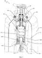
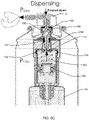
- Device 10 has a container 12, a spray cap or actuator 16, and a valve assembly for dispensing metered doses of product according to the present disclosure, which valve assembly or metered valve is generally represented by reference numeral 100.
- Container 12 can be, but is not limited to, a can, canister, or any suitable receptacle for holding a product to be dispensed from.
- Container 12 has an inner volume 14.
- Spray cap or actuator 16 operates device 10 to controls a spray rate of dispensed product.
- device 10 further has a bag 18 with product therein to be dispensed.
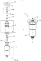
- valve housing 110 is a shell for the dosing chamber structure or body 150 that serves to provide a metered dose of product.
- valve housing 110 is a generally cylindrical shell with an inner surface 114 about a circumference thereof.
- valve housing 110 can have other shapes, such as for example, oblong, hexagonal, rectangular, and the like.
- Valve housing 110 receives dosing chamber structure 150 so that dosing chamber structure 150 is positioned in a lower portion 113 of valve housing 110.
- an upper portion 111 of valve housing 110 has a larger diameter than lower portion 113.
- Valve housing 110 has a base 116.
- a dip tube (not shown) attaches to tailpiece 118 and extends into container 12.
- Base 116 and tailpiece 118 have a bore 120 therethrough that provides fluid communication with an inner volume of valve housing 110.
- tailpiece 118 provides a surface area 122 around which a bag is welded.
- ribs 124 project radially from inner surface 114 by a rib depth.
- Ribs 124 extend vertically from base 116 to an annular ledge 128 that separates upper portion 111 and lower portion 113.
- Annular ledge provides for different internal circumferences of upper portion 111 and lower portion 113.
- Ribs 124 serve to maintain a virtually vertical or an axial alignment of body 150 shown in Fig. 3B , the dosing structure in valve housing 110. Stated another way, ribs 124 keep body 150 concentric to valve housing 110. Ribs 124 further maintain separation by a distance or the rib depth between the outer surface of dosing chamber structure 150 and inner surface 114, thereby resulting in vertically oriented channels through which product can flow therebetween.
- ribs 124 there can be three, four, five, six, seven, eight, or more ribs 124. Preferably, ribs 124 are equally spaced about inner surface 114 of valve housing 110.
- ribs 124 can also have a feature 125 to guide dosing chamber structure 150 during insertion into valve housing 110.
- Feature 125 can be, for example, an inward slanted surface at an upper end as shown.
- Ribs 124 preferably include feet 126 that project from base 116. With this configuration, feet 126 support a planar surface, such as the base of dosing structure or body 150 of Fig. 2 , so that the planar surface is vertically displaced from base 116 by the depth of the feet. This structure creates a plurality of channels below dosing chamber structure 150 through which product can flow. In some embodiments, the feet depth and rib depth are the same. In other embodiments, the feet depth is greater than the rib depth. In still other embodiments, feet depth is less than rib depth. Ribs 124 and feet 126 serve to maintain free flowing channels in metered valve 100.
- dosing chamber structure 150 is disposed in valve housing 110.
- Dosing chamber structure 150 has a lower portion or dose chamber 152 and an upper portion or stem tunnel 154.
- Dosing chamber structure 150 has a central axis with a bore 170 that communicates between an inner volume of dose chamber 152 and stem tunnel 154.
- dose chamber 152 is a hollow cylindrical body with an open bottom end 158 and a closed top end 159. Closed top end 159 has an upper surface 178 in the cylindrical body at a top end thereof. An inner annular surface of the cylindrical body is inner surface 176. An annular outer surface of dose chamber 152 is surface 179. Adjacent to top end 159, dose chamber 152 has an annular groove 172 around an outer circumference thereof. Annular groove 172 is sized to receive gasket ring 134 of Fig. 2 . In the embodiment shown, annular groove 172 is formed between two disc members having an outer diameter greater than an outer diameter of surface 179.
- At least one aperture 174 is disposed in annular groove 172 and through the body of dose chamber 152.
- each adjacent pair of apertures 174 is equally spaced apart.
- apertures 174 are equally sized, or both equally sized and equally spaced about the circumference.
- stem tunnel 154 projects vertically from top end 159.
- Stem tunnel 154 is a hollow cylindrical body with an open top end 160. Fluid communication between dose chamber 152 and stem tunnel 154 is by bore 170 through a central axis of body 150.
- Stem tunnel 154 is sized to receive valve stem 180. Further, stem tunnel has an outer diameter that is less than an outer diameter of dose chamber 152.
- Stem tunnel 154 has a disc member 156 that is horizontally disposed around an outer circumference thereof. Below disc member 156 is at least one aperture 157 through the cylindrical body of stem tunnel 154. Disc member 156 provides a top to valve housing 110.
- Disc member 156 has a top surface 166, bottom surface 162, and circumferential surface 164. Circumferential surface 164 is also a sealing surface to seal off valve housing 110.
- a plurality of triangular ribs 168 extend from the outer surface of stem tunnel 154 and along top surface 166 to circumferential surface 164. These triangular ribs 168 provide strength and maintain disc member preferably perpendicular, or at least substantially perpendicular, to a central axis of metered valve 100.
- piston 130 and piston spring 132 are inserted axially in dose chamber 152 so that the piston spring 132 is supported between upper surface 178 and piston 130.
- Piston 130 has an annular outer surface 136 that creates a fluid tight or substantially fluid tight friction seal against inner surface 176 of dose chamber 152. In this way, piston 130 seals dose chamber 152.
- Piston 130 is supported by a pedestal 131 and is axially displaceable so that when the piston moves up and down, this movement results in an increasing and decreasing, respectively, of dose chamber 152 volume. Grooves through a bottom surface of pedestal 131 form channels 133 and 135 that product can flow through when piston 130 rests on base 116.
- Piston spring 132 is preferably a coil spring that is biased against piston 130 and thus urges the piston 130 away from upper surface 178.
- a gasket ring 134 is seated in annular groove 172 and is sized to cover aperture(s) 174. With this configuration, gasket ring 134 provides a fluid/liquid tight seal between annular groove 172 and aperture(s) 174. As noted below, gasket ring 134 also serves as a one-way valve when filling container 12.
- protrusion 177 is cylindrical.
- spring 132 has a diameter larger than the protrusion 177 so that the spring circumscribes the protrusion.
- piston spring 132 is press fit around the protrusion.
- dose chamber structure 150 that includes dose chamber 152 is supported in valve housing 110 by feet 126 and ribs 124. As shown in Fig. 5A , the features of feet 126 and ribs 124 create clearance and channels, as shown in detail D, for product flow between surface 179 of dose chamber structure 150 and inner surface 114 of valve housing 110 as well as below dose chamber structure 150.
- stem spring 108 is compression coil spring.
- Stem spring 108 is axially disposed in stem tunnel 154 of body 150 and supports valve stem 180.
- Stem spring 108 provides the internal force required to return valve stem 180 to a closed position after actuation.
- stem tunnel 154 has a plurality of feet 163 disposed at a bottom end. Feet 163 are disposed about a central axis to create a seat that supports stem gasket 104.
- valve stem 180 is a cylindrical body that has a hollow, upper chamber 182 and a hollow, lower chamber 184.
- Upper chamber 182 has at least one aperture 186 disposed radially through the body.
- aperture 186 is recessed in a neck portion 187 of valve stem 180 that receives stem gasket 104.
- aperture 186 is at least two apertures on opposing sides of valve stem 180, or even three or more apertures equally spaced about a diameter of the valve stem.
- a larger cross sectional area of aperture 186 facilitates filling and dispensing of the product.
- Multiple apertures 186 allow for larger cross sectional product flow than a single aperture while at the same time using an equally sized gasket.
- Lower chamber 184 also has at least one aperture 188 disposed axially through the body of valve stem 180, and preferably at least two apertures on opposing sides. In certain embodiments, the at least two apertures, either apertures 186 or apertures 188, are three, four, or more apertures.
- Valve stem 180 moves axially in stem tunnel 154 and is biased against stem spring 108.
- Valve stem 180 has a circumferential groove 190 around an outer perimeter thereof. Circumferential groove 190 receives a selector gasket 106. By axial movement of valve stem 180, selector gasket 106 moves between a first or unactuated position that unseals and a second or actuated position that seals aperture 157.
- cup 102 mounts, orients, and seals metered valve 100 onto container 12.
- cup 102 can have a gasket (not shown).
- Cup 102 also encloses a top end of a valve housing 110.
- Cup 102 has an aperture through which a portion of valve stem 180 projects.
- Cup 102 has an inner surface that overlaps stem gasket 104.
- cup 102 serves to clamp valve stem 180, stem gasket 104, and dose chamber structure 150 together while at the same time providing a hermetic seal to container 12.
- Cup 102 also serves as an attachment platform for actuator 16 or the like, including an overcap or a spray dome.
- Stem gasket 104 maintains a gas tight seal and can also contact with product. Material selection for stem gasket 104 requires consideration of the solvent types that the stem gasket will be contacted with.
- Metered valve 100 can be connected or clinched to the aerosol can during a filling process, and can be filled according to accepted standard filling methods.
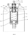
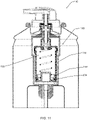
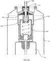
- Figs. 5A and 5B show the filling of container 12.
- Figs. 5C and 5D show dispensing.
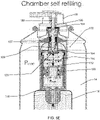
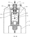
- Figs. 5E & 5F shows self-refilling.
- Fig. 5F shows filled container 12.
- valve stem 180 when valve stem 180 is pressed downward by a user, stem spring 108 is compressed as shown.
- Product flows under pressure through upper chamber 182, through aperture 186, and in the following order into and through: stem tunnel 154, aperture 188, lower chamber 184 and dose chamber 152.
- gasket ring 134 serves as a one-way valve during the filling process. Gasket ring 134 is deflected away from aperture 174 allowing the product to flow between inner surface 114 and outer surface 179 along the channels formed between ribs 124 and feet 126, and ultimately into bag 18. Piston 130 does not affect the filling process. In this position, selector gasket 106 seals aperture 157.
- Metered valve 100 surrounds piston 130 through the channels formed between ribs 124 and feet 126 and with aperture 157. This configuration enables the dispensing of high viscosity product due to the wider or larger cross-section areas that enable the product to flow more easily.
- Stem spring 108 exerts an upward force on valve stem 180 pushing it upward in stem tunnel 154 of dosing chamber structure 150.
- stem gasket 104 seals aperture 186, thereby disabling dispensing of product, whether metered or unmetered, in this state.
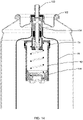
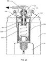
- Dose dispensing from metered valve 100 is shown in Figs. 5C and 5D .
- valve stem 180 When actuator 16 is pressed down, valve stem 180 is also pushed down, displacing alignment of aperture 186 and stem gasket 104.
- a pressure difference in dose chamber structure 150 i.e., an atmospheric pressure, causes product from the bag 18 to urge piston 130 upward to dispense all of the product that is accumulated in dose chamber 152.
- apertures 157 and 174 are sealed by their respective gaskets so that product can only flow from dose chamber 152 of dose chamber structure 150 through bore 170 into stem tunnel 154.
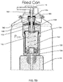
- Figs. 5E and 5F shows how dose chamber 152 of metered valve 100 is automatically refilled upon release of actuator 16.
- Stem spring 108 pushes valve stem 180 upward so that aperture 186 is sealed by stem gasket 104 and openings or aperture(s) 157 become unsealed.
- a pressure difference between the dosing chamber, i.e., atmospheric, and product in the bag 18 exists. This pressure difference causes product to flow to dose chamber 152 of dose chamber structure 150 via aperture 157, through stem tunnel 154, and bore 170. Pressurized product and together with the force of piston spring 132 push the piston 130 downward until base 116 is reached.
- the elements of the present system can be assembled sequentially, in a vertical orientation so that manufacturing is simplified by elimininating a need for a specific angle orientation.
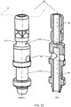
- valve stem 280 in place of valve stem 180 and selector gasket 106.
- Valve stem 280 is manufactured as a single piece from two disparate materials 282 and 284. This manufacturing can use known methods like two component injection molding and over-molding.
- Valve stem 280 functions substantially the same as the combination of valve stem 180 and selector gasket 106 except that it is a single element.
- Fig 7 provides an exemplary embodiment where dosing structure body 150 has as two discreet elements, dose chamber 152 and stem tunnel 154. Further, aperture 174 is through stem tunnel 154, instead of through dosing chamber 152.
- gasket ring 134 is disposed around stem tunnel to seal and unseal aperture 174 in accordance with the present disclosure. Accordingly, gasket 134 must be sized to fit around the stem tunnel.
- the assembly of this embodiment is easier and less complex. Gasket ring 174 needs only to stretch over the stem tunnel.
- valve stem 380 is used instead of valve stems 180 or 280.
- Valve stem 380 can be manufactured as a single piece, or like valve stem 180 can comprise a discrete gasket. Rather than a single gasket however, stem 380 has two sealing rings 382 and 384.
- a piston 230 is shown in detail in Fig. 10 and in position in the valve as shown in Fig. 11 .
- Piston 230 is used instead of piston 130.
- Piston 230 has an annular groove 232 into which an o-ring 234 is seated.
- a dosing chamber structure or body 250 is used instead of body or dosing chamber structure 150.
- Dosing chamber structure 250 unlike dosing chamber structure 150, does not have any apertures through inner surface 176 of dose chamber 152. Instead, dosing chamber structure 250 has an aperture 270 that is disposed through valve stem tunnel 154 as shown.
- FIG. 13 and 14 The present disclosure envisions embodiments without a housing. Such embodiments are shown in Fig. 13 and 14 .
- bag 18 is disposed around stem tunnel 154 to enclose all of dose chamber 152. Bag 18 is welded thereto at a designated area suitable for attachment.
- assembly 100 can also be fitted on or at an outside of a can or container 12. Assembly 100 can also be enclosed by a dome for use as separate unit for dispensing product in doses.
- metered valve 400 that is operable in a conventional product filling process to allow for the valve and bag to be vacuumed.
- Metered valve 400 will now be described with reference to Figs. 17 to 23 .
- Metered valve 400 is substantially the same as metered valve 100, but has a housing 410 instead of valve housing 110. Unlike valve housing 110, housing 410 has a groove 412 defined in outer surface 414. Within groove 412, there is at least one through hole 416 communicating with an inner volume of housing 410. Although preferably a circular aperture, through hole 416 can be a slit, or any other suitable geometry. Through hole 416 is preferably a plurality of through holes 416, or more preferably, a plurality of equally spaced through holes 416 along a circumference of groove 412. A housing gasket 418 is positioned below groove 412. Advantageously, housing gasket 418 is slideable into groove 412 during a filling process as will be discussed below.
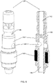
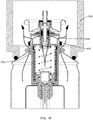
- Metered valve 400 is shown in Fig. 18 being inserted into container 12.
- a filling head 600 of a filling device is attached to container 12.
- An example of a filling device is AB175 BOV by Coster Tecnologie Speciali S.p.A. of Calceranica al Lago, Trento, Italy, although other such devices known in the art are suitable.
- metered valve 400 is held up by an inner collar of the device so that container 12, metered valve 400, and bag 18 can be vacuumed at the same time.
- this vacuuming can be performed on metered valve 400 because through hole 416 exposes the interior of housing 410 and valve mechanism to a negative pressure being applied by filling head 600.
- the arrows shown depict an exemplary vacuum flow.
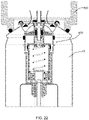
- Fig. 20 shows metered valve 400 after the vacuum process.
- a collet of filling head 600 lowers metered valve 400 into container 12.
- housing gasket 418 engages a rim of container 12 and slides into groove 412, thereby sealing through hole(s) 416.
- housing gasket 418 With housing gasket 418 now recessed or slide in groove 412 as shown in Fig. 21 , container 12 is then filled with air pressure as part of a standard under the cap filling procedure.
- metered valve 400 is cinched to container 12 and as shown in Fig. 23 , product is transferred into container 12 according to known BOV filling procedures as indicated by the arrow.
- a metered valve 500 has a bypass feature to also permit unmetered dispensing.
- Metered valve 500 has the following elements: cup 102, stem gasket 104, valve stem 180, selector gasket 106, stem spring 508, body or dose chamber structure 550, piston spring 132, piston 130 and valve housing 110.
- Dose chamber structure 550 is similar to dose chamber structure 150, however dose chamber structure 550 lacks the annular groove 172 and aperture 174 features of dose chamber structure 150. Since an annular groove and aperture are not present in this embodiment, there is a lack of a seat for a gasket ring 134. Thus, this embodiment also has no gasket ring around the dose chamber structure.
- Dose chamber structure 550 has a stem tunnel 554.
- Stem tunnel 554 is longer than stem tunnel 154 and extends down into a dose chamber 552.
- dose chamber 552 is substantially the same as dose chamber 152 except that dose chamber 552 does not have any horizontally disposed apertures, such as aperture 174.
- this embodiment uses a longer stem spring 508 than the other described embodiments to allow a longer stroke.
- Metered valve 500 operates in two different states: a first dispensing state, or metered state, where valve stem 180 is displaced by a first stroke distance to seal aperture 157 and a second dispensing state, or non-metered state, where the stem is pushed further displaced by a second stroke distance to unseal aperture 157. In the second dispensing state or non-metered state allows the product within the container to flow freely from the bag and bypass the dose dispensing chamber.
- a metered valve 500 is envisioned to be operable with actuators that have multiple strokes or allow for at least two stem states.
- metered valve 500 when metered valve 500 is in the non-metered or second dispensing state, i.e., metering disabled, metered valve 500 can also be both vacuumed and filled. That is, when aperture 188 and aperture 186 are unsealed, metered valve 500 operates bypassing the metering structures.
- metered valve 500 is in an assembled, but unactuated state.
- Fig. 25 the first dispensing state is shown, whereby product is dispensed in metered doses according to the same principles discussed above with respect to metered valves 100 and 400.
- Figs. 26 to 28 the second dispensing state is shown, with Fig. 26 showing unmetered product being dispensed, Fig. 27 showing vacuuming of the can, and Fig. 28 showing filling through the stem, as indicated by the arrows.
- valve stem 180 is displaced from about 0.85 to about 3.50 mm for the metered effect, and from about 4.00 to about 5.50 mm for the non-metered effect.
- the longer stem stroke causes valve stem 180 to travel further down in stem tunnel 554, thereby disabling selector gasket 106 that also allows the valve to be compliantly vacuumed of air.
- Selector gasket 106 allows for the dispensing in either a metered or non-metered state of high viscosity products, as well as enabling the vacuum and filling process of container 12. Again, the metered and non-metered option is achieved by using different stem pressing depth. Further, by the use of selector gasket 106 high viscosity product can be emitted or dosed upon a single actuation of valve 100.
- metered valve 500 is metered in a first state coinciding with a first stroke distance of valve stem 180 and unmetered in a second state coinciding with a second longer stroke distance of the valve stem.
- a metered valve or valve assembly 600 like metered valve 500, has a valve body 610, a container 612 with an inner volume 614, and a spray cap or actuator 616.
- container 612 can be, but is not limited to, a can, canister, or any suitable receptacle for holding a product to be dispensed from, and spray cap 616 operates device 600 to control a spray rate of dispensed product.
- device 600 also has a bag 618 with product therein to be dispensed.
- Metered valve 600 also has the bypass features of metered valve 500 to permit unmetered dispensing.
- spacer 700 is a tubular or hollow structure 710. Referring to Fig. 30 , spacer 700 has a height 740, an inner diameter 730, an outer surface 720, a top surface 780 and a bottom surface 790 (also shown in Fig. 31 ).
- spacer 700 can vary the amount of dispensed product as discussed further below.
- metered valve 600 can be manufactured to have a single set of dimensions or size for the housing 610 and valve stem 680, while the dispensing volume can be varied and controlled by the size of spacer 700.
- the volume of the dose can be reduced by reducing the volume of travel in the dose chamber by spacer 700 by an amount analogous to the height of spacer 700.
- Spacer 700 reduces the volume of the dose chamber by a volume of the spacer.
- metered valve 600 simplifies manufacturing and assembly while enhancing versatility of individual components.
- the dosage amount or dispensing volume can be adjusted, as desired for the end use application, while all other components of the metered valve 600 remain dimensionally the same.
- metered valve 600 is analogous to the metered valve 100 of Fig. 2 , in that meter valve 600 includes, in order as shown from top to bottom, cup 602, stem gasket 604, valve stem 680, selector gasket 606, stem spring 608, body or dose chamber or chamber structure 650, spacer 700, piston spring 632, piston 630 and valve housing 610.
- Valve housing 610 is a shell for the dose chamber structure or body 650 that serves to provide a metered dose of product.
- Spacer 700 is axially aligned in dose chamber 650. In certain embodiments, spacer 700 has an inner diameter that is greater than an outer diameter of stem tunnel 554 so that stem tunnel 554 extends at least partially into spacer 700.
- outer surface 720 of spacer 700 substantially coincides with the inner diameter of dose chamber 650.
- Top surface 780 of spacer 700 edges a bottom surface of dose chamber 650.
- spacer 700 is sized and maintained in position by a compression fit. The spacer interferes with the moving piston during the metered dispensing, thereby preventing piston 630 from completing a full stroke.
- a dosage is dispensed that is equal to an available volume of dose chamber 650 less a volume of spacer 700.
- piston 630 can move freely and a full stroke of the piston is possible.
- more product or a larger dosage can be dispensed in an amount equivalent to a volume of the spacer
- Spacer 700 creates an interference between an upper surface of dose chamber 650 and piston 630 to prevent dose chamber 650 from emptying completely.
- piston 630 Upon actuation, piston 630 is urged upward by internal pressure until engaging bottom surface 790.
- Dose chamber 650 is a similar to dose chamber 550 but further includes spacer 700 therein. Thus, the height and volume of spacer 700 decreases proportionally the useable volume of dose chamber 650.
- metered valve 600 operates in two different states: a first dispensing state, or metered state, where valve stem 680 is displaced by a first stroke distance to seal aperture 157 (shown better in Figure 3B ) and a second dispensing state, or non-metered state, where the stem is pushed further displaced by a second stroke distance to unseal aperture 157.
- the amount of product dispensed in the first dispensing state can be altered by the size and dimension of spacer 700.
- the second dispensing state or non-metered state allows the product in container 612 to flow freely from the bag and bypass the dose chamber 650.
- a metered valve 600 is envisioned to be operable with actuators that have multiple strokes or allow for at least two stem states.
- metered valve 600 when metered valve 600 is in the non-metered or second dispensing state, i.e., metering disabled, metered valve 600 can also be both vacuumed and filled. That is, when aperture 188 and aperture 186 (shown in Fig. 3C ) are unsealed, metered valve 600 operates bypassing the metering structures.
- Fig. 32 shows metered valve 600 in a metered state but without the spacer.
- Fig. 33 shows metered valve 600 in a metered state and with spacer 700.
- the metered state shown in Figs. 32 and 33 are at the end of the metered state.
- Spacer 700 allows for the manufacture and/or adaption of metered valve 600 to adjust to the needs of the user. Specifically, spacer 700 limits the movement of piston 630 to affect the metered amount. By the use of spacer 700, a customer can control the amount of metered product. Thus, spacer 700 can be configured as desired provided it fits in dose chamber 650 and about stem 680. Moreover, spacer 700 can be sized, especially height 740, as desired by the customer so that the metered amount is controlled as desired.
- BOV BOV
- the present disclosure is also envisioned to apply to dispensing systems that do not employ a bag.
- the ability to function as BOV makes it also fit to the medical and the food industries, and not just to personal care.
- metered valve of the present disclosure can be in place outside the container, inside the container or inside the bag (bag-on-valve).
- the term “about” means “approximately” and when used in conjunction with a number, “about” means any number within 10%, preferably 5%, and more preferably 2% of the stated number. Further, where a numerical range is provided, the range is intended to include any and all numbers within the numerical range, including the end points of the range.
- the term “substantially” means the complete or nearly complete extent or degree of an action, characteristic, property, state, structure, item, or result.
- an object that is “substantially” enclosed means that the object is either completely enclosed or nearly completely enclosed.
- the exact allowable degree of deviation from absolute completeness can in some cases depend on the specific context. However, generally, the nearness of completion will be to have the same overall result as if absolute and total completion were obtained.
Landscapes
- Chemical & Material Sciences (AREA)
- Dispersion Chemistry (AREA)
- Engineering & Computer Science (AREA)
- Mechanical Engineering (AREA)
- Containers And Packaging Bodies Having A Special Means To Remove Contents (AREA)
- Closures For Containers (AREA)
- Nozzles (AREA)
Claims (15)
- Dosierventil (100) zur Verwendung in einer Ventilbaugruppe zum Spenden einer zuvor bestimmten festen Produktmenge aus einem Behälter nach Betätigung, wobei das Ventil (100) umfasst:ein Gehäuse (110) mit einem hohlzylinderförmigen Körper mit einer offenen Oberseite, einem ebenen Boden, einer äußeren Oberfläche und einer Öffnung durch den ebenen Boden;eine hohle Dosierkammer mit einem unteren zylindrischen Körperabschnitt (152) mit einem offenen unteren Ende und einem oberen zylindrischen Körperabschnitt (154) mit einem offenen oberen Ende, wobei der obere zylindrische Körperabschnitt (154) von dem unteren zylindrischen Körperabschnitt (152) entlang einer vertikalen Achse aufragt, wobei der obere und der untere zylindrische Körperabschnitt (152, 154) über eine Öffnung durch die vertikale Achse in Fluidkommunikation miteinander stehen und wobei der obere zylindrische Körperabschnitt (154) ein ringförmiges Scheibenelement (156) aufweist, das radial davon absteht;eine ringförmige Dichtung (134), die auf dem offenen Ende des oberen zylindrischen Körperabschnitts (154) aufliegt;einen Ventilschaft (180) mit einer Bohrung in seinem oberen Abschnitt, die einen oberen Durchlass (182) bildet, einer Bohrung in seinem unteren Abschnitt, die einen unteren Durchlass (184) bildet, einer ersten horizontalen Öffnung (186) durch den Schaft (180), die mit dem oberen Durchlass (182) kommuniziert, und einer zweiten horizontalen Öffnung (188) durch den Schaft (180), die mit dem unteren Durchlass (184) kommuniziert, wobei der Schaft (180) entlang der vertikalen Achse axial verschiebbar ist und von einer ersten Feder (108) in dem oberen zylindrischen Körperabschnitt (154) so getragen wird, dass ein Teil des Schafts (180) durch die ringförmige Dichtung (134) hervorragt;ein Dichtungselement, das um einen äußeren Umfang des unteren Durchlasses (184) herum unterhalb der zweiten horizontalen Öffnung (188) angeordnet ist;einen Kolben (130), der in dem unteren zylindrischen Körperabschnitt (152) angeordnet ist und durch eine zweite Feder (132) und ein oberes Ende des unteren zylindrischen Körperabschnitts (152) gegen den ebenen Boden vorgespannt wird; undeine Dosierkammer (150) umfasst einen Hohlkörper und eine horizontal angeordnete Öffnung, wobei die horizontal angeordnete Öffnung sich unterhalb des Scheibenelements befindet und eine Fluidkommunikation mit dem Gehäuse bereitstellt, wobei die Dosierkammer (150) in dem Gehäuse (110) so angeordnet ist, dass das Scheibenelement das offene obere Ende eines Bechers (102) abdichtet,wobei der Schaft (180) um eine erste Strecke verschiebbar ist, so dass er eine abgemessene Dosis des Produkts abgibt, und um eine zweite Strecke, die größer ist als die erste Strecke, so dass er eine kontinuierliche Dosis des Produkts spendet.
- Ventil nach Anspruch 1, das ferner einen Abstandshalter (700) umfasst, dessen Größe beliebig gewählt werden kann, um die Menge an abgemessenem Produkts herbeizuführen.
- Ventil nach Anspruch 1, das ferner einen Abstandshalter (700) umfasst, der den Kolben (130) behindert und das Ausführen eines vollständigen Hubs verhindert, wodurch die dosierte Menge herbeigeführt wird.
- Ventil nach Anspruch 1, wobei die Dosierkammer (150) in dem Gehäuse (110) von einer Mehrzahl an Füßen (126) und einer Mehrzahl an Rippen (124) gestützt wird.
- Ventil nach Anspruch 4, wobei die Mehrzahl an Füßen (126) und Rippen (124) einen Abstand und Kanäle für den Produktfluss zwischen der Dosierkammer (150) und einer inneren Oberfläche des Gehäuses (110) schafft.
- Ventil nach Anspruch 1, das ferner eine Mehrzahl an vertikal angeordneten Rippen umfasst, die voneinander beabstandet sind und radial von einem Innendurchmesser des Gehäuses (110) unter Bildung von Kanälen für einen Fluidstrom dazwischen wegstehen.
- Ventil nach Anspruch 4, wobei die Mehrzahl an Füßen (126) von einer unteren Oberfläche des Gehäuses (110) nach oben ragt und um einen Umfang der unteren Oberfläche herum angeordnet ist.
- Ventil nach Anspruch 5, wobei das Ventil (100) den Kolben (130) durch die zwischen den Rippen (124) und den Füßen (126) gebildeten Kanäle umgibt, so dass die Abgabe eines hoch viskosen Produkts ermöglicht wird.
- Ventil nach Anspruch 1, wobei die ringförmige Dichtung (134) beim Befüllen des Behälters als Einwegventil dient.
- Ventil nach Anspruch 1, wobei das Gehäuse (110) ein Endstück (118) mit einem Durchlass (120) in Fluidkommunikation mit der Öffnung durch den ebenen Boden umfasst, so dass eine Fluidkommunikation mit einem Innenvolumen des Gehäuses (110) hergestellt wird.
- Ventil nach Anspruch 10, wobei das Endstück (118) direkt mit einem Beutel, der das Produkt enthält, verbunden ist.
- Ventil nach Anspruch 1, wobei die Dosierkammer (150) eine Öffnung aufweist, die durch einen Tunnel des Schafts (180) hindurch angeordnet ist, wobei der Schaft (180) einen Tunnel besitzt und wobei der Tunnel eine Öffnung aufweist und die Dichtung um den Tunnel herum angeordnet ist.
- Ventil nach Anspruch 1, wobei der obere zylindrische Körperabschnitt (152) entlang der vertikalen Achse in den unteren zylindrischen Körperabschnitt (154) hineinragt.
- Ventil nach Anspruch 1, wobei die Dosierkammer (150) nach Loslassen eines Betätigungselements (16) automatisch wieder gefüllt wird.
- Ventil nach Anspruch 1, das ferner eine Auswähldichtung (134) umfasst, die die Abgabe hoch viskoser Produkte entweder in abgemessenem oder in nicht abgemessenem Zustand ermöglicht.
Priority Applications (2)
| Application Number | Priority Date | Filing Date | Title |
|---|---|---|---|
| EP22169575.2A EP4071079B1 (de) | 2017-12-19 | 2018-09-20 | Dosierventil für ein produkt |
| EP22169576.0A EP4074622B1 (de) | 2017-12-19 | 2018-09-20 | Dosierventil für ein produkt |
Applications Claiming Priority (2)
| Application Number | Priority Date | Filing Date | Title |
|---|---|---|---|
| US201762607741P | 2017-12-19 | 2017-12-19 | |
| PCT/US2018/051948 WO2019125566A1 (en) | 2017-12-19 | 2018-09-20 | Metered valve for dispensing product |
Related Child Applications (4)
| Application Number | Title | Priority Date | Filing Date |
|---|---|---|---|
| EP22169576.0A Division EP4074622B1 (de) | 2017-12-19 | 2018-09-20 | Dosierventil für ein produkt |
| EP22169576.0A Division-Into EP4074622B1 (de) | 2017-12-19 | 2018-09-20 | Dosierventil für ein produkt |
| EP22169575.2A Division EP4071079B1 (de) | 2017-12-19 | 2018-09-20 | Dosierventil für ein produkt |
| EP22169575.2A Division-Into EP4071079B1 (de) | 2017-12-19 | 2018-09-20 | Dosierventil für ein produkt |
Publications (3)
| Publication Number | Publication Date |
|---|---|
| EP3728060A1 EP3728060A1 (de) | 2020-10-28 |
| EP3728060A4 EP3728060A4 (de) | 2021-08-18 |
| EP3728060B1 true EP3728060B1 (de) | 2022-11-02 |
Family
ID=66815596
Family Applications (3)
| Application Number | Title | Priority Date | Filing Date |
|---|---|---|---|
| EP18891920.3A Active EP3728060B1 (de) | 2017-12-19 | 2018-09-20 | Dosierventil für ein produkt |
| EP22169576.0A Active EP4074622B1 (de) | 2017-12-19 | 2018-09-20 | Dosierventil für ein produkt |
| EP22169575.2A Active EP4071079B1 (de) | 2017-12-19 | 2018-09-20 | Dosierventil für ein produkt |
Family Applications After (2)
| Application Number | Title | Priority Date | Filing Date |
|---|---|---|---|
| EP22169576.0A Active EP4074622B1 (de) | 2017-12-19 | 2018-09-20 | Dosierventil für ein produkt |
| EP22169575.2A Active EP4071079B1 (de) | 2017-12-19 | 2018-09-20 | Dosierventil für ein produkt |
Country Status (14)
| Country | Link |
|---|---|
| US (3) | US10399767B2 (de) |
| EP (3) | EP3728060B1 (de) |
| JP (3) | JP7025557B2 (de) |
| CN (1) | CN111511652A (de) |
| AR (1) | AR113647A1 (de) |
| AU (1) | AU2018390303B2 (de) |
| DE (1) | DE112018006448B4 (de) |
| ES (1) | ES2938636T3 (de) |
| GB (1) | GB2583263B (de) |
| MX (3) | MX2020005814A (de) |
| PL (1) | PL3728060T3 (de) |
| PT (3) | PT4074622T (de) |
| WO (1) | WO2019125566A1 (de) |
| ZA (2) | ZA202206472B (de) |
Families Citing this family (12)
| Publication number | Priority date | Publication date | Assignee | Title |
|---|---|---|---|---|
| FR3049275B1 (fr) * | 2016-03-23 | 2019-07-19 | Aptar France Sas | Valve doseuse et dispositif de distribution de produit fluide comportant une telle valve |
| US10399767B2 (en) * | 2017-12-19 | 2019-09-03 | Precision Valve Corporation | Metered valve for dispensing product |
| EP3536634B1 (de) | 2018-03-09 | 2021-04-28 | Aptar Radolfzell GmbH | Spender zum austrag von flüssigkeiten und betriebsverfahren hierzu |
| US10793343B1 (en) * | 2018-06-08 | 2020-10-06 | Nelson Alonso | Aerosol valve |
| EP4190716A1 (de) * | 2019-07-24 | 2023-06-07 | Lindal France SAS | Ventilteller für druckbehälter |
| US11253111B2 (en) | 2019-08-22 | 2022-02-22 | Gpcp Ip Holdings Llc | Skin care product dispensers and associated self-foaming compositions |
| PL239416B1 (pl) * | 2019-11-20 | 2021-11-29 | Marcin Kadula | Układ aerozolowego zaworu dozującego oraz pojemnik zawierający układ aerozolowego zaworu dozującego |
| US20210261401A1 (en) * | 2020-02-24 | 2021-08-26 | Healixir Health, LLC | Automated oil diffuser |
| JP7250740B2 (ja) * | 2020-09-04 | 2023-04-03 | 太平洋工業株式会社 | 定量弁、高圧容器及び喘息治療器 |
| PL243787B1 (pl) * | 2020-11-23 | 2023-10-09 | Marcin Kadula | Układ aerozolowego zaworu dawkującego |
| IT202000031442A1 (it) * | 2020-12-18 | 2022-06-18 | Coster Tecnologie Speciali Spa | Dispositivo di erogazione di una sostanza fluida |
| BE1030614B1 (nl) * | 2023-01-24 | 2024-01-12 | Tatjana Yazgheche | Een doseerinrichting voor een bag-on-valve verdeler |
Family Cites Families (45)
| Publication number | Priority date | Publication date | Assignee | Title |
|---|---|---|---|---|
| US2772820A (en) * | 1953-11-20 | 1956-12-04 | Valve Corp Of America Inc | Valve for aerosol dispenser |
| GB864392A (en) * | 1958-11-10 | 1961-04-06 | Rexall Drug Company Ltd | Improvements in or relating to dispensing devices for aerosols |
| US3018928A (en) * | 1958-11-24 | 1962-01-30 | Meshberg Philip | Metering valve |
| FR1325336A (fr) * | 1961-06-08 | 1963-04-26 | Seary Ltd | Chapeau doseur en forme de bouton-poussoir destiné à être utilisé avec des récipients sous pression |
| US3326469A (en) * | 1965-12-03 | 1967-06-20 | Precision Valve Corp | Spraying dispenser with separate holders for material and carrier fluid |
| US3377004A (en) * | 1966-10-03 | 1968-04-09 | Gen Mills Inc | Metered dispensing container |
| BE758980A (fr) * | 1970-01-21 | 1971-04-30 | Zyma Sa | Soupape doseuse |
| US3616971A (en) * | 1970-02-24 | 1971-11-02 | Precision Valve Corp | Dispenser and metering valve therefor |
| BE793319A (fr) * | 1971-12-28 | 1973-06-27 | Ciba Geigy | Distributeur aerosol pour produits fluides |
| ES444669A1 (es) * | 1975-01-29 | 1977-05-16 | Precision Valve Corp | Perfeccionamientos en valvulas distribuidoras de productos gaseosos a presion. |
| US3949939A (en) * | 1975-03-26 | 1976-04-13 | Smithkline Corporation | Metered spray device |
| GB2050303B (en) | 1979-05-21 | 1983-03-02 | Rhen Beteiligung Finanz | Dispensing valve |
| WO1988004638A1 (en) | 1986-12-17 | 1988-06-30 | Microvol Limited | Pressurised metering dispenser |
| JPH0370759A (ja) | 1989-08-11 | 1991-03-26 | Asahi Chem Ind Co Ltd | 加硫性含フッ素エラストマー組成物 |
| JPH0732462Y2 (ja) * | 1989-11-09 | 1995-07-26 | 東洋エアゾール工業株式会社 | エアゾール容器用定量弁 |
| GB9312196D0 (en) | 1993-06-14 | 1993-07-28 | Minnesota Mining & Mfg | Metered-dose aerosol valves |
| JP3066227B2 (ja) | 1993-07-22 | 2000-07-17 | 三菱樹脂株式会社 | パリソンの口栓部結晶化方法 |
| JP3274948B2 (ja) * | 1994-07-12 | 2002-04-15 | 株式会社ダイゾー | 二重エヤゾール装置の製造法および二重エヤゾール容器 |
| US5772085A (en) | 1995-03-10 | 1998-06-30 | Minnesota Mining And Manufacturing | Free flow aerosol valves |
| US6345739B1 (en) * | 1996-02-02 | 2002-02-12 | Daizo Co., Ltd. | Method for producing a double aerosol device and container therefor |
| JP3895428B2 (ja) * | 1997-05-01 | 2007-03-22 | 東洋エアゾール工業株式会社 | エアゾール容器用の定量噴射装置 |
| US6273304B1 (en) * | 1999-11-10 | 2001-08-14 | Toyo Aerosol Industry Co., Ltd. | Subdividing apparatus for aerosol container |
| GB0309936D0 (en) * | 2003-04-30 | 2003-06-04 | Bespak Plc | Improvements in valves for pressurised dispensing containers |
| BRPI0409812A (pt) | 2003-04-30 | 2006-05-09 | Bespak Plc | válvula de medição |
| US7124788B2 (en) | 2003-07-10 | 2006-10-24 | Precision Valve Corporation | Means and method for filling bag-on-valve aerosol barrier packs |
| GB0328564D0 (en) | 2003-12-10 | 2004-01-14 | Dunne Stephen T | Variable flow discharge metered dose valve |
| GB2417479B (en) | 2004-08-26 | 2006-09-13 | Bespak Plc | Improvements in metering valves for pressurised dispensing containers |
| US7726520B2 (en) | 2005-12-22 | 2010-06-01 | Innopak Inc. | Metered dispenser with feed-containing piston drive mechanism |
| FR2895735B1 (fr) * | 2005-12-30 | 2008-04-18 | Ecopack France | Valve a poche amelioree |
| GB2448294B (en) | 2006-12-13 | 2009-04-08 | Bespak Plc | Metering valve and dispensing apparatus |
| CN101595047B (zh) | 2007-01-31 | 2011-05-11 | Ips专利股份公司 | 用于分配加压流体的剂量的计量装置 |
| GB0719416D0 (en) | 2007-10-05 | 2007-11-14 | 3M Innovative Properties Co | Metered dose valve |
| US8678248B2 (en) | 2007-12-11 | 2014-03-25 | Summit Packaging Systems Inc | Metering valve |
| GB0917731D0 (en) * | 2009-10-09 | 2009-11-25 | Univ Salford | Liquid dispensing apparatus |
| FR2961795A1 (fr) * | 2010-06-28 | 2011-12-30 | Lindal France Sas | Valve de dosage pour flacon sous pression |
| US10138050B2 (en) | 2014-02-14 | 2018-11-27 | Summit Packaging Systems, Inc. | Dispensing valve incorporating a metering valve |
| US9254954B2 (en) | 2010-08-18 | 2016-02-09 | Summit Packaging Systems, Inc. | Metering valve |
| BR112013027936A2 (pt) | 2011-05-16 | 2017-01-17 | Procter & Gamble | método de fabricação de um aplicador de aerossol |
| JP5535982B2 (ja) * | 2011-05-24 | 2014-07-02 | 株式會社勝一 | 残余物排出機能を有する定量噴射容器及びそのノズル組立体 |
| CN202321216U (zh) * | 2011-12-14 | 2012-07-11 | 东莞怡信磁碟有限公司 | 一种可充式喷液瓶 |
| BE1020698A5 (nl) | 2012-05-24 | 2014-03-04 | Cruysberghs Rudiger | Verbeterd doseringsventiel. |
| US9527658B2 (en) | 2012-08-08 | 2016-12-27 | James H. Martin | Metering valve fillable through the valve |
| JP6172844B2 (ja) | 2013-04-10 | 2017-08-02 | 株式会社三谷バルブ | 噴射用ガス充填対応の正倒立バルブ機構およびこの正倒立バルブ機構を備えたエアゾール式製品 |
| US10399767B2 (en) * | 2017-12-19 | 2019-09-03 | Precision Valve Corporation | Metered valve for dispensing product |
| WO2019146289A1 (ja) * | 2018-01-29 | 2019-08-01 | 株式会社三谷バルブ | エアゾール容器の定量バルブ機構およびこの定量バルブ機構を備えたエアゾール式製品 |
-
2018
- 2018-09-20 US US16/136,752 patent/US10399767B2/en active Active
- 2018-09-20 PT PT221695760T patent/PT4074622T/pt unknown
- 2018-09-20 PT PT188919203T patent/PT3728060T/pt unknown
- 2018-09-20 PL PL18891920.3T patent/PL3728060T3/pl unknown
- 2018-09-20 CN CN201880082465.2A patent/CN111511652A/zh active Pending
- 2018-09-20 PT PT221695752T patent/PT4071079T/pt unknown
- 2018-09-20 AU AU2018390303A patent/AU2018390303B2/en active Active
- 2018-09-20 WO PCT/US2018/051948 patent/WO2019125566A1/en unknown
- 2018-09-20 DE DE112018006448.4T patent/DE112018006448B4/de active Active
- 2018-09-20 MX MX2020005814A patent/MX2020005814A/es unknown
- 2018-09-20 JP JP2020541584A patent/JP7025557B2/ja active Active
- 2018-09-20 EP EP18891920.3A patent/EP3728060B1/de active Active
- 2018-09-20 EP EP22169576.0A patent/EP4074622B1/de active Active
- 2018-09-20 EP EP22169575.2A patent/EP4071079B1/de active Active
- 2018-09-20 ES ES18891920T patent/ES2938636T3/es active Active
- 2018-09-20 GB GB2009406.6A patent/GB2583263B/en active Active
- 2018-12-18 AR ARP180103704A patent/AR113647A1/es active IP Right Grant
-
2019
- 2019-08-06 US US16/533,398 patent/US10723543B2/en active Active
-
2020
- 2020-06-29 US US16/915,232 patent/US11225372B2/en active Active
- 2020-07-13 MX MX2022004226A patent/MX2022004226A/es unknown
- 2020-07-13 MX MX2022004233A patent/MX2022004233A/es unknown
-
2022
- 2022-02-10 JP JP2022019329A patent/JP7449968B2/ja active Active
- 2022-02-10 JP JP2022019328A patent/JP7275337B2/ja active Active
- 2022-06-10 ZA ZA2022/06472A patent/ZA202206472B/en unknown
- 2022-06-10 ZA ZA2022/06471A patent/ZA202206471B/en unknown
Also Published As
Similar Documents
| Publication | Publication Date | Title |
|---|---|---|
| EP3728060B1 (de) | Dosierventil für ein produkt | |
| US5687884A (en) | Metering device for dispensing constant unit doses | |
| JPS61190467A (ja) | 加圧散布用バルブ装置 | |
| US9254954B2 (en) | Metering valve | |
| US6923342B2 (en) | Systems for dispensing multi-component products | |
| EP0101157B1 (de) | Aerosolventil | |
| JPH0784227B2 (ja) | エーロゾル分与用計量弁 | |
| JPH05254578A (ja) | 倒立姿勢で使う計量弁 | |
| JP2746586B2 (ja) | 非絞り型ポンプ組立物 | |
| JP2016510290A (ja) | 計量バルブ | |
| JPH06507140A (ja) | 流体分与容器 | |
| US3982674A (en) | Valve | |
| US6902085B2 (en) | Liquid or gel product dispenser forming a metering stick | |
| US3672545A (en) | Air pressure operated dispenser | |
| US4966313A (en) | Device enabling a spray valve to be used in any position | |
| US11787619B2 (en) | Valve for pressurized container | |
| US8408431B2 (en) | Valve | |
| AU2015218380A1 (en) | Dispensing valve incorporating a metering valve | |
| BR112020012301B1 (pt) | Válvula dosadora para dispensar produto |
Legal Events
| Date | Code | Title | Description |
|---|---|---|---|
| STAA | Information on the status of an ep patent application or granted ep patent |
Free format text: STATUS: THE INTERNATIONAL PUBLICATION HAS BEEN MADE |
|
| PUAI | Public reference made under article 153(3) epc to a published international application that has entered the european phase |
Free format text: ORIGINAL CODE: 0009012 |
|
| STAA | Information on the status of an ep patent application or granted ep patent |
Free format text: STATUS: REQUEST FOR EXAMINATION WAS MADE |
|
| 17P | Request for examination filed |
Effective date: 20200618 |
|
| AK | Designated contracting states |
Kind code of ref document: A1 Designated state(s): AL AT BE BG CH CY CZ DE DK EE ES FI FR GB GR HR HU IE IS IT LI LT LU LV MC MK MT NL NO PL PT RO RS SE SI SK SM TR |
|
| AX | Request for extension of the european patent |
Extension state: BA ME |
|
| DAV | Request for validation of the european patent (deleted) | ||
| DAX | Request for extension of the european patent (deleted) | ||
| A4 | Supplementary search report drawn up and despatched |
Effective date: 20210715 |
|
| RIC1 | Information provided on ipc code assigned before grant |
Ipc: B65D 49/02 20060101AFI20210709BHEP Ipc: B65D 83/42 20060101ALI20210709BHEP Ipc: B65D 83/44 20060101ALI20210709BHEP Ipc: B65D 83/48 20060101ALI20210709BHEP |
|
| GRAP | Despatch of communication of intention to grant a patent |
Free format text: ORIGINAL CODE: EPIDOSNIGR1 |
|
| STAA | Information on the status of an ep patent application or granted ep patent |
Free format text: STATUS: GRANT OF PATENT IS INTENDED |
|
| INTG | Intention to grant announced |
Effective date: 20220513 |
|
| GRAS | Grant fee paid |
Free format text: ORIGINAL CODE: EPIDOSNIGR3 |
|
| GRAA | (expected) grant |
Free format text: ORIGINAL CODE: 0009210 |
|
| STAA | Information on the status of an ep patent application or granted ep patent |
Free format text: STATUS: THE PATENT HAS BEEN GRANTED |
|
| AK | Designated contracting states |
Kind code of ref document: B1 Designated state(s): AL AT BE BG CH CY CZ DE DK EE ES FI FR GB GR HR HU IE IS IT LI LT LU LV MC MK MT NL NO PL PT RO RS SE SI SK SM TR |
|
| REG | Reference to a national code |
Ref country code: GB Ref legal event code: FG4D |
|
| REG | Reference to a national code |
Ref country code: CH Ref legal event code: EP Ref country code: AT Ref legal event code: REF Ref document number: 1528610 Country of ref document: AT Kind code of ref document: T Effective date: 20221115 |
|
| REG | Reference to a national code |
Ref country code: DE Ref legal event code: R096 Ref document number: 602018042716 Country of ref document: DE |
|
| REG | Reference to a national code |
Ref country code: IE Ref legal event code: FG4D |
|
| REG | Reference to a national code |
Ref country code: NL Ref legal event code: FP |
|
| REG | Reference to a national code |
Ref country code: PT Ref legal event code: SC4A Ref document number: 3728060 Country of ref document: PT Date of ref document: 20230220 Kind code of ref document: T Free format text: AVAILABILITY OF NATIONAL TRANSLATION Effective date: 20230215 |
|
| REG | Reference to a national code |
Ref country code: LT Ref legal event code: MG9D |
|
| REG | Reference to a national code |
Ref country code: ES Ref legal event code: FG2A Ref document number: 2938636 Country of ref document: ES Kind code of ref document: T3 Effective date: 20230413 |
|
| REG | Reference to a national code |
Ref country code: AT Ref legal event code: MK05 Ref document number: 1528610 Country of ref document: AT Kind code of ref document: T Effective date: 20221102 |
|
| PG25 | Lapsed in a contracting state [announced via postgrant information from national office to epo] |
Ref country code: SE Free format text: LAPSE BECAUSE OF FAILURE TO SUBMIT A TRANSLATION OF THE DESCRIPTION OR TO PAY THE FEE WITHIN THE PRESCRIBED TIME-LIMIT Effective date: 20221102 Ref country code: NO Free format text: LAPSE BECAUSE OF FAILURE TO SUBMIT A TRANSLATION OF THE DESCRIPTION OR TO PAY THE FEE WITHIN THE PRESCRIBED TIME-LIMIT Effective date: 20230202 Ref country code: LT Free format text: LAPSE BECAUSE OF FAILURE TO SUBMIT A TRANSLATION OF THE DESCRIPTION OR TO PAY THE FEE WITHIN THE PRESCRIBED TIME-LIMIT Effective date: 20221102 Ref country code: FI Free format text: LAPSE BECAUSE OF FAILURE TO SUBMIT A TRANSLATION OF THE DESCRIPTION OR TO PAY THE FEE WITHIN THE PRESCRIBED TIME-LIMIT Effective date: 20221102 Ref country code: AT Free format text: LAPSE BECAUSE OF FAILURE TO SUBMIT A TRANSLATION OF THE DESCRIPTION OR TO PAY THE FEE WITHIN THE PRESCRIBED TIME-LIMIT Effective date: 20221102 |
|
| PG25 | Lapsed in a contracting state [announced via postgrant information from national office to epo] |
Ref country code: RS Free format text: LAPSE BECAUSE OF FAILURE TO SUBMIT A TRANSLATION OF THE DESCRIPTION OR TO PAY THE FEE WITHIN THE PRESCRIBED TIME-LIMIT Effective date: 20221102 Ref country code: LV Free format text: LAPSE BECAUSE OF FAILURE TO SUBMIT A TRANSLATION OF THE DESCRIPTION OR TO PAY THE FEE WITHIN THE PRESCRIBED TIME-LIMIT Effective date: 20221102 Ref country code: IS Free format text: LAPSE BECAUSE OF FAILURE TO SUBMIT A TRANSLATION OF THE DESCRIPTION OR TO PAY THE FEE WITHIN THE PRESCRIBED TIME-LIMIT Effective date: 20230302 Ref country code: HR Free format text: LAPSE BECAUSE OF FAILURE TO SUBMIT A TRANSLATION OF THE DESCRIPTION OR TO PAY THE FEE WITHIN THE PRESCRIBED TIME-LIMIT Effective date: 20221102 Ref country code: GR Free format text: LAPSE BECAUSE OF FAILURE TO SUBMIT A TRANSLATION OF THE DESCRIPTION OR TO PAY THE FEE WITHIN THE PRESCRIBED TIME-LIMIT Effective date: 20230203 |
|
| P01 | Opt-out of the competence of the unified patent court (upc) registered |
Effective date: 20230523 |
|
| PG25 | Lapsed in a contracting state [announced via postgrant information from national office to epo] |
Ref country code: SM Free format text: LAPSE BECAUSE OF FAILURE TO SUBMIT A TRANSLATION OF THE DESCRIPTION OR TO PAY THE FEE WITHIN THE PRESCRIBED TIME-LIMIT Effective date: 20221102 Ref country code: RO Free format text: LAPSE BECAUSE OF FAILURE TO SUBMIT A TRANSLATION OF THE DESCRIPTION OR TO PAY THE FEE WITHIN THE PRESCRIBED TIME-LIMIT Effective date: 20221102 Ref country code: EE Free format text: LAPSE BECAUSE OF FAILURE TO SUBMIT A TRANSLATION OF THE DESCRIPTION OR TO PAY THE FEE WITHIN THE PRESCRIBED TIME-LIMIT Effective date: 20221102 Ref country code: DK Free format text: LAPSE BECAUSE OF FAILURE TO SUBMIT A TRANSLATION OF THE DESCRIPTION OR TO PAY THE FEE WITHIN THE PRESCRIBED TIME-LIMIT Effective date: 20221102 Ref country code: CZ Free format text: LAPSE BECAUSE OF FAILURE TO SUBMIT A TRANSLATION OF THE DESCRIPTION OR TO PAY THE FEE WITHIN THE PRESCRIBED TIME-LIMIT Effective date: 20221102 |
|
| REG | Reference to a national code |
Ref country code: DE Ref legal event code: R097 Ref document number: 602018042716 Country of ref document: DE |
|
| PG25 | Lapsed in a contracting state [announced via postgrant information from national office to epo] |
Ref country code: SK Free format text: LAPSE BECAUSE OF FAILURE TO SUBMIT A TRANSLATION OF THE DESCRIPTION OR TO PAY THE FEE WITHIN THE PRESCRIBED TIME-LIMIT Effective date: 20221102 Ref country code: AL Free format text: LAPSE BECAUSE OF FAILURE TO SUBMIT A TRANSLATION OF THE DESCRIPTION OR TO PAY THE FEE WITHIN THE PRESCRIBED TIME-LIMIT Effective date: 20221102 |
|
| PLBE | No opposition filed within time limit |
Free format text: ORIGINAL CODE: 0009261 |
|
| STAA | Information on the status of an ep patent application or granted ep patent |
Free format text: STATUS: NO OPPOSITION FILED WITHIN TIME LIMIT |
|
| 26N | No opposition filed |
Effective date: 20230803 |
|
| PGFP | Annual fee paid to national office [announced via postgrant information from national office to epo] |
Ref country code: TR Payment date: 20230906 Year of fee payment: 6 Ref country code: NL Payment date: 20230926 Year of fee payment: 6 Ref country code: IT Payment date: 20230921 Year of fee payment: 6 |
|
| PG25 | Lapsed in a contracting state [announced via postgrant information from national office to epo] |
Ref country code: SI Free format text: LAPSE BECAUSE OF FAILURE TO SUBMIT A TRANSLATION OF THE DESCRIPTION OR TO PAY THE FEE WITHIN THE PRESCRIBED TIME-LIMIT Effective date: 20221102 |
|
| PGFP | Annual fee paid to national office [announced via postgrant information from national office to epo] |
Ref country code: PT Payment date: 20230905 Year of fee payment: 6 Ref country code: PL Payment date: 20230905 Year of fee payment: 6 Ref country code: FR Payment date: 20230925 Year of fee payment: 6 Ref country code: BE Payment date: 20230927 Year of fee payment: 6 |
|
| PGFP | Annual fee paid to national office [announced via postgrant information from national office to epo] |
Ref country code: ES Payment date: 20231002 Year of fee payment: 6 |
|
| REG | Reference to a national code |
Ref country code: DE Ref legal event code: R119 Ref document number: 602018042716 Country of ref document: DE |
|
| REG | Reference to a national code |
Ref country code: CH Ref legal event code: PL |
|
| PG25 | Lapsed in a contracting state [announced via postgrant information from national office to epo] |
Ref country code: LU Free format text: LAPSE BECAUSE OF NON-PAYMENT OF DUE FEES Effective date: 20230920 |