EP3723970B1 - Verfahren und vorrichtung zum reinigen einer vulkanisierungsform - Google Patents
Verfahren und vorrichtung zum reinigen einer vulkanisierungsform Download PDFInfo
- Publication number
- EP3723970B1 EP3723970B1 EP18839824.2A EP18839824A EP3723970B1 EP 3723970 B1 EP3723970 B1 EP 3723970B1 EP 18839824 A EP18839824 A EP 18839824A EP 3723970 B1 EP3723970 B1 EP 3723970B1
- Authority
- EP
- European Patent Office
- Prior art keywords
- mould
- cleaning
- cleaned
- dry ice
- location
- Prior art date
- Legal status (The legal status is an assumption and is not a legal conclusion. Google has not performed a legal analysis and makes no representation as to the accuracy of the status listed.)
- Active
Links
Images


Classifications
-
- B—PERFORMING OPERATIONS; TRANSPORTING
- B29—WORKING OF PLASTICS; WORKING OF SUBSTANCES IN A PLASTIC STATE IN GENERAL
- B29C—SHAPING OR JOINING OF PLASTICS; SHAPING OF MATERIAL IN A PLASTIC STATE, NOT OTHERWISE PROVIDED FOR; AFTER-TREATMENT OF THE SHAPED PRODUCTS, e.g. REPAIRING
- B29C33/00—Moulds or cores; Details thereof or accessories therefor
- B29C33/70—Maintenance
- B29C33/72—Cleaning
-
- B—PERFORMING OPERATIONS; TRANSPORTING
- B24—GRINDING; POLISHING
- B24C—ABRASIVE OR RELATED BLASTING WITH PARTICULATE MATERIAL
- B24C1/00—Methods for use of abrasive blasting for producing particular effects; Use of auxiliary equipment in connection with such methods
- B24C1/003—Methods for use of abrasive blasting for producing particular effects; Use of auxiliary equipment in connection with such methods using material which dissolves or changes phase after the treatment, e.g. ice, CO2
-
- B—PERFORMING OPERATIONS; TRANSPORTING
- B24—GRINDING; POLISHING
- B24C—ABRASIVE OR RELATED BLASTING WITH PARTICULATE MATERIAL
- B24C3/00—Abrasive blasting machines or devices; Plants
- B24C3/02—Abrasive blasting machines or devices; Plants characterised by the arrangement of the component assemblies with respect to each other
- B24C3/06—Abrasive blasting machines or devices; Plants characterised by the arrangement of the component assemblies with respect to each other movable; portable
-
- B—PERFORMING OPERATIONS; TRANSPORTING
- B24—GRINDING; POLISHING
- B24C—ABRASIVE OR RELATED BLASTING WITH PARTICULATE MATERIAL
- B24C3/00—Abrasive blasting machines or devices; Plants
- B24C3/32—Abrasive blasting machines or devices; Plants designed for abrasive blasting of particular work, e.g. the internal surfaces of cylinder blocks
- B24C3/325—Abrasive blasting machines or devices; Plants designed for abrasive blasting of particular work, e.g. the internal surfaces of cylinder blocks for internal surfaces, e.g. of tubes
-
- B—PERFORMING OPERATIONS; TRANSPORTING
- B25—HAND TOOLS; PORTABLE POWER-DRIVEN TOOLS; MANIPULATORS
- B25J—MANIPULATORS; CHAMBERS PROVIDED WITH MANIPULATION DEVICES
- B25J11/00—Manipulators not otherwise provided for
- B25J11/008—Manipulators for service tasks
- B25J11/0085—Cleaning
-
- B—PERFORMING OPERATIONS; TRANSPORTING
- B25—HAND TOOLS; PORTABLE POWER-DRIVEN TOOLS; MANIPULATORS
- B25J—MANIPULATORS; CHAMBERS PROVIDED WITH MANIPULATION DEVICES
- B25J19/00—Accessories fitted to manipulators, e.g. for monitoring, for viewing; Safety devices combined with or specially adapted for use in connection with manipulators
- B25J19/02—Sensing devices
- B25J19/021—Optical sensing devices
- B25J19/022—Optical sensing devices using lasers
-
- B—PERFORMING OPERATIONS; TRANSPORTING
- B25—HAND TOOLS; PORTABLE POWER-DRIVEN TOOLS; MANIPULATORS
- B25J—MANIPULATORS; CHAMBERS PROVIDED WITH MANIPULATION DEVICES
- B25J19/00—Accessories fitted to manipulators, e.g. for monitoring, for viewing; Safety devices combined with or specially adapted for use in connection with manipulators
- B25J19/02—Sensing devices
- B25J19/021—Optical sensing devices
- B25J19/023—Optical sensing devices including video camera means
-
- B—PERFORMING OPERATIONS; TRANSPORTING
- B25—HAND TOOLS; PORTABLE POWER-DRIVEN TOOLS; MANIPULATORS
- B25J—MANIPULATORS; CHAMBERS PROVIDED WITH MANIPULATION DEVICES
- B25J19/00—Accessories fitted to manipulators, e.g. for monitoring, for viewing; Safety devices combined with or specially adapted for use in connection with manipulators
- B25J19/02—Sensing devices
- B25J19/026—Acoustical sensing devices
-
- B—PERFORMING OPERATIONS; TRANSPORTING
- B25—HAND TOOLS; PORTABLE POWER-DRIVEN TOOLS; MANIPULATORS
- B25J—MANIPULATORS; CHAMBERS PROVIDED WITH MANIPULATION DEVICES
- B25J5/00—Manipulators mounted on wheels or on carriages
- B25J5/007—Manipulators mounted on wheels or on carriages mounted on wheels
-
- B—PERFORMING OPERATIONS; TRANSPORTING
- B25—HAND TOOLS; PORTABLE POWER-DRIVEN TOOLS; MANIPULATORS
- B25J—MANIPULATORS; CHAMBERS PROVIDED WITH MANIPULATION DEVICES
- B25J9/00—Programme-controlled manipulators
- B25J9/16—Programme controls
- B25J9/1656—Programme controls characterised by programming, planning systems for manipulators
- B25J9/1664—Programme controls characterised by programming, planning systems for manipulators characterised by motion, path, trajectory planning
-
- B—PERFORMING OPERATIONS; TRANSPORTING
- B29—WORKING OF PLASTICS; WORKING OF SUBSTANCES IN A PLASTIC STATE IN GENERAL
- B29D—PRODUCING PARTICULAR ARTICLES FROM PLASTICS OR FROM SUBSTANCES IN A PLASTIC STATE
- B29D30/00—Producing pneumatic or solid tyres or parts thereof
- B29D30/06—Pneumatic tyres or parts thereof (e.g. produced by casting, moulding, compression moulding, injection moulding, centrifugal casting)
- B29D30/0601—Vulcanising tyres; Vulcanising presses for tyres
- B29D30/0662—Accessories, details or auxiliary operations
- B29D2030/0663—Mould maintenance, e.g. cleaning, washing, repairing
Definitions
- the present invention relates to the field of tire curing and more particularly to the cleaning of molds used for tire vulcanization.
- Tires are usually obtained by molding and vulcanizing a raw casing inside a mold installed in a curing press.
- the vulcanizing mold generally comprises sectors which form, after vulcanization, the radially outer surface or tread of the tire and shells arranged axially on either side of the sectors and form the sidewalls of the tire.
- the outer walls of the casing are pressed against the inner metal walls of the curing mold by means of a curing membrane which is expandable under the effect of a pressurized heat transfer fluid.
- the tread pattern of the mold linings and that of the shells is then imprinted on the raw casing which is then vulcanized using heat.
- Sectors and shells are metallic and are usually obtained by casting and mechanical machining techniques and sometimes have a coating layer.
- the sector patterns are often complex and the sectors may have vent holes. After a number of castings have been made, the mold must be cleaned to remove molding residues, e.g. rubber, oil, grease, which stick to the casting parts and clog the vent holes.
- sandblasting There are various techniques for cleaning vulcanization molds, including sandblasting, but this does not allow you to clean all the corners of the sectors properly, in addition, sand is very abrasive and can damage the molding surface and remove the coating from it when present. In addition, the sand used for cleaning must be removed.
- Another technique for cleaning molds is also known using a laser beam device, but it takes a lot of time and requires simultaneous suction of fumes and residues. In addition to its large size (its generator takes up a lot of space and is not suitable for cleaning a mold in the baking press), such a laser beam device can be dangerous for the user.
- Dry ice particles are projected at high speed against the walls of the mold, the ice sublimates on contact with the hot walls of the mold and instantly detaches the residues which are carried away by the resulting gases or are subsequently evacuated.
- an operator equipped with a dry ice lance comes as close as possible to a cooking press and operates the lance manually inside the mold.
- the dry ice projected inside the mold manages to clean it well, but in working conditions that are quite difficult for the operator, particularly in terms of noise (the noise generated by the cleaning operation reaches sound intensities of around 100 to 120 dB), danger linked to the temperature of the mold, poor visibility of the interior of the mold to be cleaned and, ultimately, fatigue.
- the document EP 2695728 describes a device for automatically cleaning vulcanization molds using dry ice.
- the device comprises an annular support carrying two spray nozzles and which is connected via a fixing arm to the frame of the device.
- the annular support contains linear guidance and translational movement systems for the cleaning nozzles in two orthogonal directions, each nozzle being furthermore moved in translation by a motorized arm in a direction perpendicular to the plane of the first two.
- the annular support is arranged so as to come face to face with a mold to be cleaned. While it certainly allows automatic cleaning of a vulcanization mold, this device nevertheless has the disadvantage of being very complex and bulky, which poses problems for cleaning molds in a press as well as molds of small dimensions.
- An objective of the invention is to remedy the aforementioned drawbacks and to provide an original solution making it possible to improve the ergonomics, flexibility and quality of cleaning of one or more tire vulcanization molds, while minimizing the time lost during operations related to cleaning.
- the cryogenic cleaning method of a vulcanization mold uses an autonomous cleaning apparatus which, when it receives a cleaning mission instruction from a control unit, navigates to the mold to be cleaned and automatically cleans it, without the intervention of an operator.
- the cleaning is carried out automatically, by controlling the movement of the spray nozzle on the basis of the 3D file of the mold to be cleaned or the dimensions (height, diameter) of the mold or on the basis of the images of the mold transmitted by a camera.
- the cleaning instructions are pre-programmed or sent by the control unit. The movement of the spray nozzle is thus adapted to the mold to be cleaned, which allows precise trajectories of the spray nozzle.
- the device performs cleaning using dry ice sprayed at high speed inside a hot mold located in the cooking press, which allows for fast and complete cleaning, of high quality, because it allows to remove even residues located in places that are difficult to access or poorly lit, or even subject to steam emissions, and this without causing ergonomic problems for a user. It allows for a gain in productivity, because the device, as soon as it is supplied with dry ice and electricity, can chain cleanings without waiting.
- said device communicates with at least one operator.
- the communication between the cleaning appliance and the operator is bilateral.
- the appliance can only start cleaning after receiving a cleaning mission instruction transmitted by the operator who accesses the control unit.
- the operator is of course provided with means of communication with the appliance (smartwatch, tablet, etc.) and can move around the workshop safely after communicating with the appliance.
- the communication is unilateral, from the appliance to the operator, which allows the user to be informed of the status of the appliance or the progress of the appliance's cleaning mission. This allows the operator to move away from the location that is being cleaned, which avoids any discomfort related to the loud noise during cleaning.
- said device communicates with an automatic control system for a cooking workshop in which the cooking press containing the mold to be cleaned is located.
- the curing workshop control system is a curing management system, it manages the inputs and outputs of raw tire blanks and cured tires from the workshop and manages the operation of all curing presses. This control system also counts the number of curing operations performed by a mold and decides when it must be cleaned. By making it communicate directly with the cleaning device, we ensure cleaning of the mold at the right time, without waiting time, because this can be done even outside the operators' working hours. We can also make the operator who checked the cured tire communicate with the curing workshop control system, which sends the cleaning device a mission instruction to clean the mold that has cured the checked tire and on which the operator has detected a defect.
- the method comprises a step in which the cleaning apparatus navigates around the obstacles identified during its navigation.
- AGVs autonomous guided vehicles
- control unit After receiving the information that the cleaning of the vulcanization mold is finished, the control unit sends a new vulcanization mold cleaning mission instruction to said device. This makes it possible to chain the cleaning operations, for greater efficiency.
- the device connects to an electrical charging socket and a compressed air socket adjacent to the base of the cooking press. This saves the energy stored in its batteries and gives the cleaning device more autonomy.
- the method comprises a step in which said apparatus returns to its storage location as soon as the dry ice filling level of the tank has fallen below a predetermined limit. This allows to ensure the quality of cleaning, the cleaning process can be resumed as soon as there is sufficient ice.
- said apparatus automatically refills its dry ice reservoir.
- the apparatus can drive to the dry ice storage reservoir and refill automatically, thereby saving time.
- the method comprises a step of blowing or suctioning the cleaning residues. This makes it possible to quickly evacuate all the cleaning residues and obtain a clean and operational vulcanization mold.
- the apparatus comprises means for communicating with at least one operator.
- the device comprises means of communication with an automaton for controlling a cooking workshop in which the cooking press comprising the mold to be cleaned is located.
- the apparatus includes navigation means enabling it to avoid obstacles.
- the device comprises means for identifying its location near the cooking press comprising the mold to be cleaned and means for connection to an electrical charging socket and to a compressed air socket adjacent to the base of the press.
- the apparatus comprises sensors for measuring the level of dry ice filling of the tank which are connected to said control system which sends an instruction to the control module for the return of the apparatus to its storage location as soon as the level of dry ice filling of the tank has fallen below a predetermined limit.
- the device comprises means for blowing or sucking up cleaning residues.
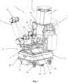
- the apparatus 1 comprises a collaborative mobile robot 10 comprising an autonomous mobile platform 2 on which is mounted an articulated arm 3 which carries a spray nozzle 4 connected to a dry ice dispenser and which moves with the platform.
- the autonomous mobile platform 2 comprises a chassis 20 of generally rectangular shape. The chassis is supported by two pairs of front and rear wheels 22, mounted freely in rotation, and it is moved by two differential wheels 21, each being driven in rotation by an electric motor.
- the autonomous mobile platform 20 also integrates electrical power supply batteries (not shown in the drawings).
- the autonomous mobile platform 2 further comprises sensors for scanning and identifying the environment, a microprocessor control device and wireless communication means, for example by wifi with a remote control unit.
- Such an autonomous mobile platform is for example of the MiR 200 TM type proposed by Mobile Industrial Robots ApS. It can carry up to 200 kg of load, it includes several sensors (ultrasonic and laser) and a 3D camera integrated connected to the microprocessor control unit of the platform.
- the autonomous mobile platform 20 is thus led to scan its environment, it identifies obstacles or people, which it manages to avoid, while calculating the most efficient route to move to its destination.
- the platform control device is connected to the on-board control system of the cleaning device, for example by an Ethernet type link.
- the articulated arm 3 is a collaborative robot arm that is mounted on the autonomous mobile platform 2 from which it receives power and control in operation. It goes without saying that the platform integrates proximity sensors that detect the approach of an operator or an object.
- the robot is of the collaborative type and includes force sensors that act on the collaborative robot accordingly in a generally known manner, in particular from the document US 9,669,548 .
- the force sensors of the collaborative robot act when the autonomous platform is stopped.
- the arm articulated arm 3 is of the collaborative robot type with six axes of rotation and comprises several arm sections articulated relative to each other.
- the last section 31 of the articulated arm 3 comprises an effector 32 which holds the body 41 of a spray nozzle 4 so that the nozzle moves with the arm.
- the body 41 of the spray nozzle 4 is extended by a lance 43.
- the lance 43 is covered with a sleeve 42 made of a material which has good thermal insulation properties, such as insulating wool, expanded polystyrene, etc.
- the spray nozzle is connected by means of a flexible hose (not shown in the drawings) to a dry ice dispenser, as will be explained in the following.
- a frame 5 is fixedly mounted on the upper face of the autonomous mobile platform 2.
- the frame 5 is metallic and forms a supporting structure for certain components of the vulcanization mold cleaning apparatus.
- the frame 5 comprises a first part 51 for supporting the articulated arm 3 and a second part 52 forming a support for other components of the apparatus.
- the articulated arm 3 is mounted at the front end of the part 51 of the frame 5 while being raised and offset relative to the front end of the mobile platform 2 so as to be able to more easily access the interior of the mold to be cleaned.
- the second part 52 of the frame 5 supports a dry ice dispenser 6 and an on-board control system 7.
- the dry ice dispenser 6 comprises a tank 61 which contains dry dry ice pellets at a temperature of approximately -78°C.
- the dry ice pellets have a cylindrical shape with a diameter of approximately 2 to 3 mm and a height of a few mm.
- dry ice microcrystals can be used.
- the dry ice pellets or microcrystals pass from the tank 61 into a distribution enclosure 62 from which they are projected at approximately 300 m/s onto the surface to be cleaned using compressed air.
- the compressed air at a pressure of between 1 and 15 bars arrives in the enclosure 62 from the compressed air network of the cooking workshop or from a compressor carried by the autonomous mobile platform 2.
- the enclosure 62 is connected to a fan carried by the autonomous platform.
- the entrance to enclosure 62 is equipped with a solenoid valve (not illustrated in the drawings) which is controlled by the control system 7 of the apparatus.
- the tank 61, the enclosure 62 and the pipes for transferring dry ice to the spray nozzle 4 are covered with thermal insulating materials.
- the control system 7 of the cleaning device is connected to the control device of the autonomous platform 2 which uses an on-board navigation system.
- the device includes in its memory a map of the workshop (which can be drawn by the device or downloaded from a digital medium) and is able to orient itself and navigate (it calculates its trajectory according to the starting point, the arrival point and the obstacles encountered) using SLAM (Simultaneous Localisation And Mapping) type algorithms.
- SLAM Simultaneous Localisation And Mapping
- the control system 7 is connected to the control and navigation device of the autonomous platform 2 which receives information from the sensors of the device to identify the location of the mold to be cleaned.
- the control and navigation device is connected to said sensors to adjust the position of the device and detect the location of the mold to be cleaned and possibly the objects to be avoided on its trajectory when it moves between a storage location of the device and the location of the mold to be cleaned.
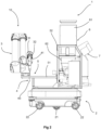
- the device also comprises wireless communication means, for example by wifi, with a remote control unit 100 which has the role of supervisor for the operation of the device, unit which transmits to it a mission instruction for cleaning the vulcanization mold.
- the onboard control system 7 is of the microprocessor computer type, therefore comprising one or more CPU processor units and RAM and ROM memories.
- the apparatus also includes a control module which allows the actuation of its components according to the instruction received from the control unit 100 via the control system 7.
- the cleaning device also includes a GSM type communication module with at least one operator.
- Each operator is equipped with a receiver device such as a smart watch, tablet or smartphone.
- a receiver device such as a smart watch, tablet or smartphone.
- the cleaning apparatus When not engaged in cleaning a vulcanization mold, the cleaning apparatus is placed in a storage location in which it is connected to an electrical charging station (not shown in the drawings).
- the storage location is provided with means for supplying dry ice from a storage tank or a dry ice manufacturing machine.
- the device 1 navigates to the location of the curing press containing the vulcanizing mold to be cleaned and parks next to it.
- the base of the curing press is equipped with a power supply terminal 8 for electricity and compressed air.
- the power supply terminal 8 is best seen at figure 3 . It comprises a mark 81 which is a shape recognition mark, the shape of the mark having been previously recorded in the memory of the cleaning device. Terminal 8 also comprises a compressed air supply socket 82 and an electrical supply socket 83.
- the compressed air connection is made via a quick pneumatic coupling with instant connection of the type marketed by the company PARKER HANNIFIN.
- the electrical connection is made using a quick coupling of the SELFPLUG ® magnetic coupling type from the company GULPLUG.
- the device 1 is placed in front of the mark 81, which ensures the precise positioning of the corresponding coupling socket of its compressed air connection hose in front of the compressed air socket 82 and of its respective electrical connector in front of the electrical supply socket 83.
- the cleaning appliance has an on-board compressor and carries enough electrical energy in its batteries that it does not need to connect to terminal 8.
- the cleaning apparatus directs the spray nozzle 4 towards the inside of the mould to be cleaned in accordance with the instructions received from its control system 7.
- the dry ice sprayed under pressure against the hot parts of the vulcanisation mould to be cleaned causes on the one hand a mechanical shock, due to the impact at high speed of the ice particles against the walls of the mold, and, on the other hand, a thermal shock, due to the difference in temperatures (approximately 170°C for the hot mold and around -78°C for the dry ice). Following the cumulative effects of the mechanical shock and the thermal shock, the molding residues detach from the wall of the mold.
- the dry ice passes directly from the solid state to the gaseous state, its volume is significantly increased (by approximately 800 times), which carries with it part of the cleaning residues.
- the solenoid valve which allows access of the dry ice into the enclosure 62 is closed and the nozzle 4 sends compressed air towards the mold, which allows the cleaning residues to be evacuated.
- the compressed air supply is blocked in the enclosure 62, which is then placed in communication with a fan which allows suction via the nozzle 4 (the access of the dry ice into the enclosure still being prevented by the solenoid valve).
- the suction action of the fan of the device allows the cleaning residues to be sucked via the nozzle 4 into the enclosure 62 which communicates for this purpose with an additional storage tank via a non-return valve (not illustrated in the drawings).
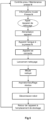
- FIG. 5 is a block diagram that illustrates the main steps of the vulcanization mold cleaning operation according to a first embodiment.
- the cleaning device thus communicates with the workshop control unit and performs the operation automatically according to the steps indicated on the figure 5 .
- This is a completely automatic cleaning operation.
- the cleaning of the vulcanization mold is decided after checking the cured tire or for preventive maintenance requested by the control unit of the curing workshop.
- the information is transmitted to the control or supervision unit, in this case the control unit of the curing workshop, which calls the cleaning device to carry out a vulcanization mold cleaning mission.
- the device checks the dry ice filling level of its tank and the charging level of its batteries and, if necessary, it recharges, then it leaves the storage location.
- the device moves autonomously to the press "N" to be cleaned for which it has received the cleaning mission instruction.
- the device knows the location of the press and calculates its optimum path for to get there in autonomous navigation mode.
- the device connects to compressed air and electricity at the power supply terminal provided for this purpose at the foot of the press. Once connected, the device starts the cleaning operation according to a pre-established program and based on the data received from the central unit. The mold is thus cleaned, the residues being removed during a blowing or suction operation carried out by the cleaning device. The collaborative mobile robot is then automatically disconnected by the device. The cleaning device returns to its storage location in autonomous navigation mode and waits for a new instruction.
- FIG. 6 is a block diagram that represents the steps of the vulcanization mold cleaning operation according to a second embodiment.
- the starting point is the inspection step of the cured tire, but the order is given this time by an operator, who is the expert in vulcanization molds, and who transmits his instructions via an interface of the control unit of the device.
- the cleaning device moves autonomously and performs the cleaning automatically, but it communicates with the operator who intervenes at certain steps before transmitting an instruction to the device. This is a semi-automatic cleaning operation.
- the vulcanization mold expert is called to check the mold that cured the checked tire and decides on a mold cleaning operation, either entirely or only on a part or area that produced defects on the tire.
- the expert then sends a cleaning mission instruction to the device.
- the device checks the dry ice filling level of its tank and the charging level of its batteries and, if necessary, it recharges, then it leaves the storage location.
- the device moves autonomously to the press to be cleaned "N" for which it received the cleaning mission instruction.
- the device knows the location of the press and calculates its optimum route to get there in autonomous navigation mode.
- the device stops and the operator connects it to compressed air and electricity at the power supply terminal provided for this purpose at the foot of the press.
- the expert sends the device an instruction to carry out a cleaning program that he has chosen. after performing the mold inspection.
- the device performs the cleaning operation. Once the mold has been cleaned, the residues are removed by a blowing or suction operation performed by the cleaning device.
- the device communicates with the expert to inform him of the end of the cleaning.
- the expert checks the quality of the cleaning carried out and disconnects the collaborative mobile robot.
- the device then returns to its storage location in autonomous navigation mode and waits for a new instruction.
- an autonomous guided vehicle instead of an autonomous platform guided by its sensors and a map based on SLAM-type algorithms, an autonomous guided vehicle, known by the abbreviation AGV, can be used, which navigates by following, for example, a magnetic rail, or by using radar.
- AGV autonomous guided vehicle
- a cleaning device comprising an autonomous guided vehicle comprises the same components as the one previously described.
- the cleaning device returns to its storage location as soon as the control system detects a malfunction of one of its components.
Landscapes
- Engineering & Computer Science (AREA)
- Mechanical Engineering (AREA)
- Robotics (AREA)
- Physics & Mathematics (AREA)
- Multimedia (AREA)
- Optics & Photonics (AREA)
- Acoustics & Sound (AREA)
- Moulds For Moulding Plastics Or The Like (AREA)
Claims (15)
- Verfahren zum Reinigen einer Vulkanisationsform für Reifen in einer Vulkanisierpresse mithilfe eines Geräts, das einen kollaborativen mobilen Roboter (10) aufweist, der ein Computerprogramm beinhaltet, wobei der Roboter eine autonome mobile Plattform (2), die auf Antriebsrädern montiert ist und Stromversorgungsbatterien aufweist, eine Trockeneisausgabeeinrichtung (6), Sensoren zur Identifizierung des Platzes der zu reinigenden Form und Motoren, die sein Bewegen zwischen einem Lagerplatz des Geräts und der zu reinigenden Form sowie das Bewegen eines beweglichen Gelenkarms (3) des Roboters gewährleisten, aufweist, wobei der Arm eine Sprühdüse (4) für Trockeneis aus der Ausgabeeinrichtung trägt, wobei das Gerät Mittel zur Kommunikation mit einer Steuereinheit umfasst, um die folgenden Vorgänge durchzuführen:- nachdem es eine Reinigungsauftragsanweisung für eine Vulkanisationsform erhalten hat und nachdem es den Stromladestand seiner Batterien und den Trockeneisfüllstand eines Tanks (61) der Ausgabeeinrichtung überprüft hat, seinen Lagerplatz zu verlassen;- automatisch zu dem Platz der zu reinigenden Form zu navigieren;- die Umgebung, in der sich die Vulkanisierpresse mit der zu reinigenden Form befindet, und gegebenenfalls Hindernisse automatisch zu scannen;- die Vulkanisierpresse mit der zu reinigenden Form automatisch zu identifizieren und sich in deren Nähe zu positionieren;- die Vulkanisationsform automatisch zu reinigen, indem der die Sprühdüse (4) tragende Arm gemäß einer Menge von Anweisungen in das Innere der Form geführt wird, so dass sie mit Trockeneis gereinigt wird;- mit der Steuereinheit zu kommunizieren, um sie über den Fortschritt des Reinigungsvorgangs zu informieren.
- Verfahren nach dem vorhergehenden Anspruch, dadurch gekennzeichnet, dass das Gerät mit mindestens einer Bedienperson kommuniziert.
- Verfahren nach einem der Ansprüche 1 oder 2, dadurch gekennzeichnet, dass das Gerät mit einem Steuerungsautomaten einer Vulkanisierwerkstatt kommuniziert, in der sich die Vulkanisierpresse mit der zu reinigenden Form befindet.
- Verfahren nach einem der vorhergehenden Ansprüche, dadurch gekennzeichnet, dass die Steuereinheit, nachdem sie die Information erhalten hat, dass die Reinigung der Vulkanisationsform beendet ist, eine neue Reinigungsauftragsanweisung für eine Vulkanisationsform an das Gerät sendet.
- Verfahren nach einem der vorhergehenden Ansprüche, dadurch gekennzeichnet, dass sich das Gerät, nachdem es die Vulkanisierpresse mit der zu reinigenden Form identifiziert hat, an eine Stromladesteckdose und an eine Druckluftsteckdose anschließt, die an den Sockel der Vulkanisierpresse angrenzen.
- Verfahren nach einem der vorhergehenden Ansprüche, dadurch gekennzeichnet, dass es einen Schritt umfasst, bei dem das Gerät an seinen Lagerplatz zurückkehrt, sobald der Trockeneisfüllstand des Tanks unter einen vorbestimmten Grenzwert gesunken ist.
- Verfahren nach Anspruch 6, dadurch gekennzeichnet, dass das Gerät seinen Tank automatisch wieder mit Trockeneis auffüllt.
- Verfahren nach einem der vorhergehenden Ansprüche, dadurch gekennzeichnet, dass es einen Schritt des Abblasens oder Absaugens der Reinigungsrückstände umfasst.
- Reinigungsgerät, das geeignet ist, eine Vulkanisationsform für Reifen in einer Vulkanisierpresse zu reinigen, aufweisend:- einen kollaborativen mobilen Roboter (10), der ein Computerprogramm beinhaltet, wobei der Roboter eine autonome mobile Plattform (2) aufweist, die auf Antriebsrädern montiert ist und Stromversorgungsbatterien aufweist;- eine Trockeneisausgabeeinrichtung (6), die mit einer Sprühdüse (4) verbunden ist, die von einem beweglichen Gelenkarm (3) des Roboters getragen wird;- Motoren, die sein Bewegen zwischen einem Lagerplatz des Geräts und der zu reinigenden Vulkanisationsform sowie das Bewegen des Gelenkarms gewährleisten;- Mittel zur Kommunikation mit einer Steuereinheit, die ihm eine Reinigungsauftragsanweisung für eine Vulkanisationsform übermittelt;- Sensoren, um den Platz der zu reinigenden Form zu identifizieren, und ein Steuersystem, das ein Navigationssystem verwendet;- wobei das Steuersystem mit den Sensoren verbunden ist, um die Position des Geräts zu justieren und den Platz der zu reinigenden Form und gegebenenfalls die Gegenstände auf seiner Bahn, wenn es sich zwischen einem Lagerplatz des Geräts und dem Platz der zu reinigenden Form bewegt, zu detektieren;- einen Speicher zur Speicherung digitaler Daten;- ein Bedienmodul, welches das Betätigen seiner Komponenten in Abhängigkeit von der von der Steuereinheit empfangenen Anweisung ermöglicht.
- Gerät nach Anspruch 9, dadurch gekennzeichnet, dass das Bedienmodul einen Prozessor umfasst, der, wenn er eine Reinigungsauftragsanweisung von der Steuereinheit empfängt, dazu programmiert ist:- den Stromladestand seiner Batterien und den Trockeneisfüllstand seines Tanks zu überprüfen,- dem Gerät zu ermöglichen, seinen Lagerplatz zu verlassen; und- automatisch zu dem Platz der zu reinigenden Form zu navigieren; und- die Umgebung, in der sich die Vulkanisierpresse mit der zu reinigenden Form befindet, und gegebenenfalls Hindernisse automatisch zu scannen; sowie- die Vulkanisierpresse mit der zu reinigenden Form automatisch zu identifizieren und sich in deren Nähe zu positionieren; und- die Vulkanisationsform automatisch zu reinigen, indem der die Sprühdüse tragende Arm gemäß einer Menge von Anweisungen in das Innere der Form geführt wird, so dass sie mit Trockeneis gereinigt wird; und- mit der Steuereinheit zu kommunizieren, um sie über den Fortschritt des Reinigungsvorgangs zu informieren.
- Gerät nach einem der Ansprüche 9 oder 10, dadurch gekennzeichnet, dass es Mittel zur Kommunikation mit mindestens einer Bedienperson umfasst.
- Gerät nach einem der Ansprüche 9 bis 11, dadurch gekennzeichnet, dass es Mittel zur Kommunikation mit einem Steuerungsautomaten einer Vulkanisierwerkstatt umfasst, in der sich die Vulkanisierpresse mit der zu reinigenden Form befindet.
- Gerät nach einem der Ansprüche 9 bis 12, dadurch gekennzeichnet, dass es Mittel zur Identifizierung seines Platzes bei der Vulkanisierpresse mit der zu reinigenden Form und Mittel zum Anschließen an eine Stromladesteckdose und an eine Druckluftsteckdose, die an den Sockel der Presse angrenzen, umfasst.
- Gerät nach einem der Ansprüche 9 bis 13, dadurch gekennzeichnet, dass es Sensoren zum Messen des Trockeneisfüllstands des Tanks aufweist, die mit dem Steuersystem verbunden sind, das eine Anweisung an das Bedienmodul zum Zurückkehren des Geräts an seinen Lagerplatz sendet, sobald der Trockeneisfüllstand des Tanks unter einen vorbestimmten Grenzwert gesunken ist.
- Gerät nach einem der Ansprüche 9 bis 14, dadurch gekennzeichnet, dass es Mittel zum Abblasen oder Absaugen der Reinigungsrückstände umfasst.
Applications Claiming Priority (2)
| Application Number | Priority Date | Filing Date | Title |
|---|---|---|---|
| FR1762145 | 2017-12-14 | ||
| PCT/FR2018/053245 WO2019115947A1 (fr) | 2017-12-14 | 2018-12-13 | Procede et appareil de nettoyage d'un moule de vulcanisation |
Publications (2)
| Publication Number | Publication Date |
|---|---|
| EP3723970A1 EP3723970A1 (de) | 2020-10-21 |
| EP3723970B1 true EP3723970B1 (de) | 2024-12-11 |
Family
ID=61521649
Family Applications (1)
| Application Number | Title | Priority Date | Filing Date |
|---|---|---|---|
| EP18839824.2A Active EP3723970B1 (de) | 2017-12-14 | 2018-12-13 | Verfahren und vorrichtung zum reinigen einer vulkanisierungsform |
Country Status (5)
| Country | Link |
|---|---|
| US (1) | US11992977B2 (de) |
| EP (1) | EP3723970B1 (de) |
| CN (1) | CN111465487B (de) |
| PL (1) | PL3723970T3 (de) |
| WO (1) | WO2019115947A1 (de) |
Families Citing this family (10)
| Publication number | Priority date | Publication date | Assignee | Title |
|---|---|---|---|---|
| JP6590010B2 (ja) * | 2018-02-09 | 2019-10-16 | 横浜ゴム株式会社 | 加硫用モールドの洗浄装置および方法 |
| US11407118B1 (en) * | 2018-12-10 | 2022-08-09 | Joseph E Augenbraun | Robot for performing dextrous tasks and related methods and systems |
| IT201900024406A1 (it) * | 2019-12-18 | 2021-06-18 | Primon Automazioni Srl | Struttura di robot mobile su navetta, particolarmente per lo scarico ed il carico di macchine di ritorcitura, filatura, roccatura, orditura, o tufting. |
| DE102020200467A1 (de) * | 2020-01-16 | 2021-07-22 | Continental Reifen Deutschland Gmbh | Reinigungsanlage sowie Reinigungsverfahren |
| CN114346987B (zh) * | 2021-12-16 | 2023-08-04 | 杭州申昊科技股份有限公司 | 一种防爆机器人的散热装置 |
| CN114750439B (zh) * | 2022-03-24 | 2023-12-29 | 安徽华泰尔环保科技有限公司 | 一种用于橡胶轮胎加工的硫化设备及其使用方法 |
| FR3140784B1 (fr) * | 2022-10-13 | 2024-10-25 | Ynsect | Système de nettoyage d’une structure de stockage comportant des alvéoles, ensemble et procédé correspondants. |
| CN115488915B (zh) * | 2022-11-14 | 2023-04-14 | 山东玲珑轮胎股份有限公司 | 一种硫化机机械手抓盘张开闭合度自动调整装置 |
| DE102023200238A1 (de) * | 2023-01-12 | 2024-07-18 | Continental Reifen Deutschland Gmbh | Unstetigförderer |
| CN118254310B (zh) * | 2024-01-16 | 2024-11-22 | 江苏库米特激光智能装备有限公司 | 一种轮胎模具激光清洗装置及使用方法 |
Citations (3)
| Publication number | Priority date | Publication date | Assignee | Title |
|---|---|---|---|---|
| DE19830397A1 (de) * | 1998-07-08 | 2000-01-20 | Diw Instandhaltung Gmbh | Vorrichtung und Verfahren zum Reinigen von Vulkanisierformen |
| FR2916152A1 (fr) * | 2007-05-14 | 2008-11-21 | Robosoft Sa | Robot polyvalent |
| WO2016105308A1 (en) * | 2014-12-25 | 2016-06-30 | Lang Yuzer Otomotiv Yan Sanayi Ve Ticaret Anonim Sirketi | Sidewall cleaning machine for tire curing mold |
Family Cites Families (11)
| Publication number | Priority date | Publication date | Assignee | Title |
|---|---|---|---|---|
| US6369353B1 (en) * | 1998-02-20 | 2002-04-09 | The Goodyear Tire & Rubber Company | Robotic laser tire mold cleaning system and method of use |
| US8437875B2 (en) * | 2008-10-27 | 2013-05-07 | Eusebio Guillermo Hernandez | Outdoor home cleaning robot |
| DE102012107225A1 (de) | 2012-08-07 | 2014-02-13 | enotech AG | Vorrichtung und Verfahren zum Reinigen von Vulkanisationsformen |
| CN203170637U (zh) * | 2013-04-19 | 2013-09-04 | 厦门金瑞镒贸易有限公司 | 一种自动干冰清洗轮胎模具的装置 |
| FR3005130B1 (fr) | 2013-04-24 | 2015-04-17 | Sonceboz Sa | Actionneur electrique a tige filetee |
| CN104941851B (zh) * | 2014-03-26 | 2018-07-20 | 安川(中国)机器人有限公司 | 清洗机器人系统及清洗方法和涂装机器人系统及涂装方法 |
| JP6140114B2 (ja) | 2014-07-31 | 2017-05-31 | ファナック株式会社 | 移動式人協調型ロボット |
| TR201415813A2 (tr) * | 2014-12-25 | 2016-07-21 | Lang Yuezer Otomotiv Yan San Ve Tic A S | Lastik kürlenme kalıbı temizleme robotu. |
| FR3042639B1 (fr) | 2015-10-20 | 2017-12-08 | Moving Magnet Tech | Actionneur lineaire a stabilite magnetique et force d'arrachement ameliorees |
| CN205614893U (zh) * | 2016-04-19 | 2016-10-05 | 河源市新天彩科技有限公司 | 一种摆动式吹气装置 |
| CN107053552A (zh) * | 2017-04-21 | 2017-08-18 | 烟台拓伟智能科技股份有限公司 | 硫化机模具自动清洗系统 |
-
2018
- 2018-12-13 PL PL18839824.2T patent/PL3723970T3/pl unknown
- 2018-12-13 US US16/772,412 patent/US11992977B2/en active Active
- 2018-12-13 WO PCT/FR2018/053245 patent/WO2019115947A1/fr not_active Ceased
- 2018-12-13 EP EP18839824.2A patent/EP3723970B1/de active Active
- 2018-12-13 CN CN201880080006.0A patent/CN111465487B/zh active Active
Patent Citations (3)
| Publication number | Priority date | Publication date | Assignee | Title |
|---|---|---|---|---|
| DE19830397A1 (de) * | 1998-07-08 | 2000-01-20 | Diw Instandhaltung Gmbh | Vorrichtung und Verfahren zum Reinigen von Vulkanisierformen |
| FR2916152A1 (fr) * | 2007-05-14 | 2008-11-21 | Robosoft Sa | Robot polyvalent |
| WO2016105308A1 (en) * | 2014-12-25 | 2016-06-30 | Lang Yuzer Otomotiv Yan Sanayi Ve Ticaret Anonim Sirketi | Sidewall cleaning machine for tire curing mold |
Also Published As
| Publication number | Publication date |
|---|---|
| PL3723970T3 (pl) | 2025-04-28 |
| EP3723970A1 (de) | 2020-10-21 |
| US20210078211A1 (en) | 2021-03-18 |
| CN111465487A (zh) | 2020-07-28 |
| CN111465487B (zh) | 2022-06-14 |
| US11992977B2 (en) | 2024-05-28 |
| WO2019115947A1 (fr) | 2019-06-20 |
Similar Documents
| Publication | Publication Date | Title |
|---|---|---|
| EP3723970B1 (de) | Verfahren und vorrichtung zum reinigen einer vulkanisierungsform | |
| US8646404B2 (en) | Modular system with platformed robot, booth, and fluid delivery system for tire spraying | |
| US20230257139A1 (en) | Products, Systems, and Methods for an Autonomous Drone Docking Station | |
| EP2872878B1 (de) | Vorrichtung zum versprühen eines farbstoffeindringungsprüfprodukts auf ein werkstück | |
| CN111348004B (zh) | 用于对车辆进行自主清洁的服务站 | |
| JP2007536927A (ja) | 成形機 | |
| CN106541329B (zh) | 集成设备 | |
| US20160074988A1 (en) | Processing module, processing apparatus, and processing method | |
| CN114054272A (zh) | 一种激光清洗管道内壁及防腐的装置及除锈喷漆的方法 | |
| CN106540895A (zh) | 清洗系统 | |
| FR2990639A1 (fr) | "installation pour la fabrication de recipients comportant un robot agence pour intervenir sur au moins deux unites" | |
| EP3880593B1 (de) | Verfahren und anlage zur übertragung von spulen | |
| EP3880594B1 (de) | Verfahren und anlage zur bereitstellung elastomerer produkte | |
| CN108058153B (zh) | 自主移动体和用于自主移动体的存储介质 | |
| US6283825B1 (en) | Automatic trimmer machine | |
| EP1413362B1 (de) | Verfahren und Kabine zur Vorbereitung und Lackierung von Oberflächen im selben Raum | |
| EP3084144B1 (de) | Vorrichtung zur reinigung eines turbomaschinenmoduls | |
| KR100742717B1 (ko) | 타이어금형용 드라이아이스 세척장치 | |
| FR3128652A1 (fr) | Dispositif polyvalent et automatisé d’élimination des défauts de surface par abrasion | |
| JP6870125B1 (ja) | Hsstタイヤの製造プロセス、およびhsstタイヤの製造システム、並びにhsstタイヤの製造プロセスで製造されたhsstタイヤ | |
| CN220233102U (zh) | 晶圆减薄设备 | |
| TWI409139B (zh) | 鍍膜及滾圓設備 | |
| JP2009066702A (ja) | レンズのクリーニング方法およびクリーニング装置 | |
| EP3814026B1 (de) | Reinigungssystem und verfahren zur graffitientfernung | |
| US20210031242A1 (en) | Spray applicator apparatuses for generating uniform spray patterns and methods incorporating the same |
Legal Events
| Date | Code | Title | Description |
|---|---|---|---|
| STAA | Information on the status of an ep patent application or granted ep patent |
Free format text: STATUS: UNKNOWN |
|
| STAA | Information on the status of an ep patent application or granted ep patent |
Free format text: STATUS: THE INTERNATIONAL PUBLICATION HAS BEEN MADE |
|
| PUAI | Public reference made under article 153(3) epc to a published international application that has entered the european phase |
Free format text: ORIGINAL CODE: 0009012 |
|
| STAA | Information on the status of an ep patent application or granted ep patent |
Free format text: STATUS: REQUEST FOR EXAMINATION WAS MADE |
|
| 17P | Request for examination filed |
Effective date: 20200714 |
|
| AK | Designated contracting states |
Kind code of ref document: A1 Designated state(s): AL AT BE BG CH CY CZ DE DK EE ES FI FR GB GR HR HU IE IS IT LI LT LU LV MC MK MT NL NO PL PT RO RS SE SI SK SM TR |
|
| AX | Request for extension of the european patent |
Extension state: BA ME |
|
| DAV | Request for validation of the european patent (deleted) | ||
| DAX | Request for extension of the european patent (deleted) | ||
| STAA | Information on the status of an ep patent application or granted ep patent |
Free format text: STATUS: EXAMINATION IS IN PROGRESS |
|
| 17Q | First examination report despatched |
Effective date: 20220322 |
|
| REG | Reference to a national code |
Ref country code: DE Ref legal event code: R079 Free format text: PREVIOUS MAIN CLASS: B29D0030060000 Ipc: B29C0033720000 Ref country code: DE Ref legal event code: R079 Ref document number: 602018077564 Country of ref document: DE Free format text: PREVIOUS MAIN CLASS: B29D0030060000 Ipc: B29C0033720000 |
|
| GRAP | Despatch of communication of intention to grant a patent |
Free format text: ORIGINAL CODE: EPIDOSNIGR1 |
|
| STAA | Information on the status of an ep patent application or granted ep patent |
Free format text: STATUS: GRANT OF PATENT IS INTENDED |
|
| RIC1 | Information provided on ipc code assigned before grant |
Ipc: B24C 3/32 20060101ALI20240715BHEP Ipc: B24C 3/06 20060101ALI20240715BHEP Ipc: B24C 1/00 20060101ALI20240715BHEP Ipc: B25J 19/02 20060101ALI20240715BHEP Ipc: B25J 11/00 20060101ALI20240715BHEP Ipc: G05D 1/00 20060101ALI20240715BHEP Ipc: B25J 5/00 20060101ALI20240715BHEP Ipc: B29D 30/06 20060101ALI20240715BHEP Ipc: B29C 33/72 20060101AFI20240715BHEP |
|
| INTG | Intention to grant announced |
Effective date: 20240729 |
|
| GRAS | Grant fee paid |
Free format text: ORIGINAL CODE: EPIDOSNIGR3 |
|
| GRAA | (expected) grant |
Free format text: ORIGINAL CODE: 0009210 |
|
| STAA | Information on the status of an ep patent application or granted ep patent |
Free format text: STATUS: THE PATENT HAS BEEN GRANTED |
|
| AK | Designated contracting states |
Kind code of ref document: B1 Designated state(s): AL AT BE BG CH CY CZ DE DK EE ES FI FR GB GR HR HU IE IS IT LI LT LU LV MC MK MT NL NO PL PT RO RS SE SI SK SM TR |
|
| REG | Reference to a national code |
Ref country code: GB Ref legal event code: FG4D Free format text: NOT ENGLISH |
|
| REG | Reference to a national code |
Ref country code: CH Ref legal event code: EP |
|
| REG | Reference to a national code |
Ref country code: IE Ref legal event code: FG4D Free format text: LANGUAGE OF EP DOCUMENT: FRENCH |
|
| REG | Reference to a national code |
Ref country code: DE Ref legal event code: R096 Ref document number: 602018077564 Country of ref document: DE |
|
| REG | Reference to a national code |
Ref country code: LT Ref legal event code: MG9D |
|
| PG25 | Lapsed in a contracting state [announced via postgrant information from national office to epo] |
Ref country code: HR Free format text: LAPSE BECAUSE OF FAILURE TO SUBMIT A TRANSLATION OF THE DESCRIPTION OR TO PAY THE FEE WITHIN THE PRESCRIBED TIME-LIMIT Effective date: 20241211 |
|
| PGFP | Annual fee paid to national office [announced via postgrant information from national office to epo] |
Ref country code: DE Payment date: 20250121 Year of fee payment: 7 |
|
| PG25 | Lapsed in a contracting state [announced via postgrant information from national office to epo] |
Ref country code: FI Free format text: LAPSE BECAUSE OF FAILURE TO SUBMIT A TRANSLATION OF THE DESCRIPTION OR TO PAY THE FEE WITHIN THE PRESCRIBED TIME-LIMIT Effective date: 20241211 |
|
| PG25 | Lapsed in a contracting state [announced via postgrant information from national office to epo] |
Ref country code: BG Free format text: LAPSE BECAUSE OF FAILURE TO SUBMIT A TRANSLATION OF THE DESCRIPTION OR TO PAY THE FEE WITHIN THE PRESCRIBED TIME-LIMIT Effective date: 20241211 |
|
| REG | Reference to a national code |
Ref country code: NL Ref legal event code: MP Effective date: 20241211 |
|
| PG25 | Lapsed in a contracting state [announced via postgrant information from national office to epo] |
Ref country code: ES Free format text: LAPSE BECAUSE OF FAILURE TO SUBMIT A TRANSLATION OF THE DESCRIPTION OR TO PAY THE FEE WITHIN THE PRESCRIBED TIME-LIMIT Effective date: 20241211 |
|
| PG25 | Lapsed in a contracting state [announced via postgrant information from national office to epo] |
Ref country code: NO Free format text: LAPSE BECAUSE OF FAILURE TO SUBMIT A TRANSLATION OF THE DESCRIPTION OR TO PAY THE FEE WITHIN THE PRESCRIBED TIME-LIMIT Effective date: 20250311 |
|
| PG25 | Lapsed in a contracting state [announced via postgrant information from national office to epo] |
Ref country code: GR Free format text: LAPSE BECAUSE OF FAILURE TO SUBMIT A TRANSLATION OF THE DESCRIPTION OR TO PAY THE FEE WITHIN THE PRESCRIBED TIME-LIMIT Effective date: 20250312 Ref country code: LV Free format text: LAPSE BECAUSE OF FAILURE TO SUBMIT A TRANSLATION OF THE DESCRIPTION OR TO PAY THE FEE WITHIN THE PRESCRIBED TIME-LIMIT Effective date: 20241211 |
|
| PGFP | Annual fee paid to national office [announced via postgrant information from national office to epo] |
Ref country code: FR Payment date: 20250205 Year of fee payment: 7 Ref country code: CZ Payment date: 20250131 Year of fee payment: 7 |
|
| PG25 | Lapsed in a contracting state [announced via postgrant information from national office to epo] |
Ref country code: RS Free format text: LAPSE BECAUSE OF FAILURE TO SUBMIT A TRANSLATION OF THE DESCRIPTION OR TO PAY THE FEE WITHIN THE PRESCRIBED TIME-LIMIT Effective date: 20250311 |
|
| PG25 | Lapsed in a contracting state [announced via postgrant information from national office to epo] |
Ref country code: NL Free format text: LAPSE BECAUSE OF FAILURE TO SUBMIT A TRANSLATION OF THE DESCRIPTION OR TO PAY THE FEE WITHIN THE PRESCRIBED TIME-LIMIT Effective date: 20241211 |
|
| REG | Reference to a national code |
Ref country code: AT Ref legal event code: MK05 Ref document number: 1750057 Country of ref document: AT Kind code of ref document: T Effective date: 20241211 |
|
| PG25 | Lapsed in a contracting state [announced via postgrant information from national office to epo] |
Ref country code: SM Free format text: LAPSE BECAUSE OF FAILURE TO SUBMIT A TRANSLATION OF THE DESCRIPTION OR TO PAY THE FEE WITHIN THE PRESCRIBED TIME-LIMIT Effective date: 20241211 |
|
| PGFP | Annual fee paid to national office [announced via postgrant information from national office to epo] |
Ref country code: PL Payment date: 20250203 Year of fee payment: 7 |
|
| PG25 | Lapsed in a contracting state [announced via postgrant information from national office to epo] |
Ref country code: IS Free format text: LAPSE BECAUSE OF FAILURE TO SUBMIT A TRANSLATION OF THE DESCRIPTION OR TO PAY THE FEE WITHIN THE PRESCRIBED TIME-LIMIT Effective date: 20250411 |
|
| PGFP | Annual fee paid to national office [announced via postgrant information from national office to epo] |
Ref country code: IT Payment date: 20250328 Year of fee payment: 7 |
|
| PG25 | Lapsed in a contracting state [announced via postgrant information from national office to epo] |
Ref country code: PT Free format text: LAPSE BECAUSE OF FAILURE TO SUBMIT A TRANSLATION OF THE DESCRIPTION OR TO PAY THE FEE WITHIN THE PRESCRIBED TIME-LIMIT Effective date: 20250411 |
|
| PG25 | Lapsed in a contracting state [announced via postgrant information from national office to epo] |
Ref country code: EE Free format text: LAPSE BECAUSE OF FAILURE TO SUBMIT A TRANSLATION OF THE DESCRIPTION OR TO PAY THE FEE WITHIN THE PRESCRIBED TIME-LIMIT Effective date: 20241211 |
|
| PG25 | Lapsed in a contracting state [announced via postgrant information from national office to epo] |
Ref country code: RO Free format text: LAPSE BECAUSE OF FAILURE TO SUBMIT A TRANSLATION OF THE DESCRIPTION OR TO PAY THE FEE WITHIN THE PRESCRIBED TIME-LIMIT Effective date: 20241211 Ref country code: AT Free format text: LAPSE BECAUSE OF FAILURE TO SUBMIT A TRANSLATION OF THE DESCRIPTION OR TO PAY THE FEE WITHIN THE PRESCRIBED TIME-LIMIT Effective date: 20241211 |
|
| PG25 | Lapsed in a contracting state [announced via postgrant information from national office to epo] |
Ref country code: SK Free format text: LAPSE BECAUSE OF FAILURE TO SUBMIT A TRANSLATION OF THE DESCRIPTION OR TO PAY THE FEE WITHIN THE PRESCRIBED TIME-LIMIT Effective date: 20241211 |
|
| REG | Reference to a national code |
Ref country code: CH Ref legal event code: PL |
|
| PG25 | Lapsed in a contracting state [announced via postgrant information from national office to epo] |
Ref country code: LU Free format text: LAPSE BECAUSE OF NON-PAYMENT OF DUE FEES Effective date: 20241213 |
|
| PG25 | Lapsed in a contracting state [announced via postgrant information from national office to epo] |
Ref country code: SE Free format text: LAPSE BECAUSE OF FAILURE TO SUBMIT A TRANSLATION OF THE DESCRIPTION OR TO PAY THE FEE WITHIN THE PRESCRIBED TIME-LIMIT Effective date: 20241211 |
|
| REG | Reference to a national code |
Ref country code: DE Ref legal event code: R097 Ref document number: 602018077564 Country of ref document: DE |
|
| PG25 | Lapsed in a contracting state [announced via postgrant information from national office to epo] |
Ref country code: MC Free format text: LAPSE BECAUSE OF FAILURE TO SUBMIT A TRANSLATION OF THE DESCRIPTION OR TO PAY THE FEE WITHIN THE PRESCRIBED TIME-LIMIT Effective date: 20241211 |
|
| REG | Reference to a national code |
Ref country code: BE Ref legal event code: MM Effective date: 20241231 |
|
| PG25 | Lapsed in a contracting state [announced via postgrant information from national office to epo] |
Ref country code: DK Free format text: LAPSE BECAUSE OF FAILURE TO SUBMIT A TRANSLATION OF THE DESCRIPTION OR TO PAY THE FEE WITHIN THE PRESCRIBED TIME-LIMIT Effective date: 20241211 |
|
| PG25 | Lapsed in a contracting state [announced via postgrant information from national office to epo] |
Ref country code: BE Free format text: LAPSE BECAUSE OF NON-PAYMENT OF DUE FEES Effective date: 20241231 |
|
| PLBE | No opposition filed within time limit |
Free format text: ORIGINAL CODE: 0009261 |
|
| STAA | Information on the status of an ep patent application or granted ep patent |
Free format text: STATUS: NO OPPOSITION FILED WITHIN TIME LIMIT |
|
| PG25 | Lapsed in a contracting state [announced via postgrant information from national office to epo] |
Ref country code: CH Free format text: LAPSE BECAUSE OF NON-PAYMENT OF DUE FEES Effective date: 20241231 |
|
| PG25 | Lapsed in a contracting state [announced via postgrant information from national office to epo] |
Ref country code: IE Free format text: LAPSE BECAUSE OF NON-PAYMENT OF DUE FEES Effective date: 20241213 |
|
| 26N | No opposition filed |
Effective date: 20250912 |
|
| GBPC | Gb: european patent ceased through non-payment of renewal fee |
Effective date: 20250311 |