EP3720726B1 - Heizmodul für eine heizanlage eines bewohnbaren fahrzeugs - Google Patents
Heizmodul für eine heizanlage eines bewohnbaren fahrzeugs Download PDFInfo
- Publication number
- EP3720726B1 EP3720726B1 EP18815148.4A EP18815148A EP3720726B1 EP 3720726 B1 EP3720726 B1 EP 3720726B1 EP 18815148 A EP18815148 A EP 18815148A EP 3720726 B1 EP3720726 B1 EP 3720726B1
- Authority
- EP
- European Patent Office
- Prior art keywords
- air
- heating
- heating module
- module
- section
- Prior art date
- Legal status (The legal status is an assumption and is not a legal conclusion. Google has not performed a legal analysis and makes no representation as to the accuracy of the status listed.)
- Active
Links
- 238000010438 heat treatment Methods 0.000 title claims description 389
- 239000004020 conductor Substances 0.000 claims description 2
- 238000006073 displacement reaction Methods 0.000 description 41
- 239000007789 gas Substances 0.000 description 15
- 238000013461 design Methods 0.000 description 14
- 238000004891 communication Methods 0.000 description 12
- 238000011144 upstream manufacturing Methods 0.000 description 7
- 238000009434 installation Methods 0.000 description 6
- 230000006378 damage Effects 0.000 description 4
- 230000005611 electricity Effects 0.000 description 4
- 238000002156 mixing Methods 0.000 description 4
- 230000001681 protective effect Effects 0.000 description 4
- 230000007704 transition Effects 0.000 description 4
- 238000012546 transfer Methods 0.000 description 3
- 244000089486 Phragmites australis subsp australis Species 0.000 description 2
- 238000004026 adhesive bonding Methods 0.000 description 2
- 238000004378 air conditioning Methods 0.000 description 2
- 238000010586 diagram Methods 0.000 description 2
- 238000005485 electric heating Methods 0.000 description 2
- 230000005484 gravity Effects 0.000 description 2
- 238000000265 homogenisation Methods 0.000 description 2
- 238000005259 measurement Methods 0.000 description 2
- 238000013021 overheating Methods 0.000 description 2
- RYGMFSIKBFXOCR-UHFFFAOYSA-N Copper Chemical compound [Cu] RYGMFSIKBFXOCR-UHFFFAOYSA-N 0.000 description 1
- 238000009529 body temperature measurement Methods 0.000 description 1
- 238000002485 combustion reaction Methods 0.000 description 1
- 230000001276 controlling effect Effects 0.000 description 1
- 229910052802 copper Inorganic materials 0.000 description 1
- 239000010949 copper Substances 0.000 description 1
- 230000001419 dependent effect Effects 0.000 description 1
- 238000011161 development Methods 0.000 description 1
- 230000018109 developmental process Effects 0.000 description 1
- 230000000694 effects Effects 0.000 description 1
- 239000000463 material Substances 0.000 description 1
- 239000000203 mixture Substances 0.000 description 1
- 230000001105 regulatory effect Effects 0.000 description 1
- 238000009423 ventilation Methods 0.000 description 1
Images


Classifications
-
- B—PERFORMING OPERATIONS; TRANSPORTING
- B60—VEHICLES IN GENERAL
- B60H—ARRANGEMENTS OF HEATING, COOLING, VENTILATING OR OTHER AIR-TREATING DEVICES SPECIALLY ADAPTED FOR PASSENGER OR GOODS SPACES OF VEHICLES
- B60H1/00—Heating, cooling or ventilating [HVAC] devices
- B60H1/22—Heating, cooling or ventilating [HVAC] devices the heat being derived otherwise than from the propulsion plant
- B60H1/2215—Heating, cooling or ventilating [HVAC] devices the heat being derived otherwise than from the propulsion plant the heat being derived from electric heaters
-
- B—PERFORMING OPERATIONS; TRANSPORTING
- B60—VEHICLES IN GENERAL
- B60H—ARRANGEMENTS OF HEATING, COOLING, VENTILATING OR OTHER AIR-TREATING DEVICES SPECIALLY ADAPTED FOR PASSENGER OR GOODS SPACES OF VEHICLES
- B60H1/00—Heating, cooling or ventilating [HVAC] devices
- B60H1/00357—Air-conditioning arrangements specially adapted for particular vehicles
- B60H1/00364—Air-conditioning arrangements specially adapted for particular vehicles for caravans or trailers
-
- B—PERFORMING OPERATIONS; TRANSPORTING
- B60—VEHICLES IN GENERAL
- B60H—ARRANGEMENTS OF HEATING, COOLING, VENTILATING OR OTHER AIR-TREATING DEVICES SPECIALLY ADAPTED FOR PASSENGER OR GOODS SPACES OF VEHICLES
- B60H1/00—Heating, cooling or ventilating [HVAC] devices
- B60H1/00507—Details, e.g. mounting arrangements, desaeration devices
- B60H1/00514—Details of air conditioning housings
- B60H1/00542—Modular assemblies
-
- F—MECHANICAL ENGINEERING; LIGHTING; HEATING; WEAPONS; BLASTING
- F24—HEATING; RANGES; VENTILATING
- F24H—FLUID HEATERS, e.g. WATER OR AIR HEATERS, HAVING HEAT-GENERATING MEANS, e.g. HEAT PUMPS, IN GENERAL
- F24H3/00—Air heaters
- F24H3/02—Air heaters with forced circulation
- F24H3/04—Air heaters with forced circulation the air being in direct contact with the heating medium, e.g. electric heating element
- F24H3/0405—Air heaters with forced circulation the air being in direct contact with the heating medium, e.g. electric heating element using electric energy supply, e.g. the heating medium being a resistive element; Heating by direct contact, i.e. with resistive elements, electrodes and fins being bonded together without additional element in-between
- F24H3/0429—For vehicles
-
- B—PERFORMING OPERATIONS; TRANSPORTING
- B60—VEHICLES IN GENERAL
- B60H—ARRANGEMENTS OF HEATING, COOLING, VENTILATING OR OTHER AIR-TREATING DEVICES SPECIALLY ADAPTED FOR PASSENGER OR GOODS SPACES OF VEHICLES
- B60H1/00—Heating, cooling or ventilating [HVAC] devices
- B60H1/00007—Combined heating, ventilating, or cooling devices
- B60H1/00021—Air flow details of HVAC devices
- B60H2001/00078—Assembling, manufacturing or layout details
- B60H2001/00092—Assembling, manufacturing or layout details of air deflecting or air directing means inside the device
-
- B—PERFORMING OPERATIONS; TRANSPORTING
- B60—VEHICLES IN GENERAL
- B60H—ARRANGEMENTS OF HEATING, COOLING, VENTILATING OR OTHER AIR-TREATING DEVICES SPECIALLY ADAPTED FOR PASSENGER OR GOODS SPACES OF VEHICLES
- B60H1/00—Heating, cooling or ventilating [HVAC] devices
- B60H1/22—Heating, cooling or ventilating [HVAC] devices the heat being derived otherwise than from the propulsion plant
- B60H2001/2268—Constructional features
Definitions
- the invention relates to a heating module for a heating system of a habitable vehicle.
- habitable vehicle refers to all types of powered or non-powered vehicles in which one or more people can live. Such habitable vehicles are in particular mobile homes, caravans or ships or boats.
- Previous heating systems for habitable vehicles are based on the principle that heated air exits from a usually central heating system into the habitable space or is distributed to different locations in the habitable space via a system of pipes or hoses.
- This heater usually houses a heating unit (electric or gas operated) and a fan. In order to be able to guarantee an appropriate heating output, more powerful and therefore generally larger heaters are required for a larger habitable room.
- a heating arrangement for heating a medium flowing through the heating arrangement is known, with a housing with a first and a second housing part.
- a heating assembly is arranged in the housing.
- the DE 10 2010 060 446 A1 discloses an electric heater with a fluid-conducting housing in which a helical radiator is accommodated.
- the invention is based on the object of providing a flexible heating module for a heating system, which requires little space and can be functionally integrated into the heating system.
- the heating module allows connection to other components, resulting in a heating system overall.
- Such a heating module which in particular does not have its own blower device, can be flexibly installed and used in a heating system.
- the space requirement of the heating module is very small.
- the air inlet opening can be designed to be connectable to a blower device separate from the heating module.
- the heating module is an independent heater.
- the heating module preferably has a blower device.
- the heating module has a sensor device which is set up to detect the temperature of the air flowing through the heating module.
- the heating module can have a control device that is set up to control the heating module.
- the control device can have an interface that is set up to provide a communication connection to a device separate from the heating module.
- the heating module can also be integrated into a heating system for control purposes.
- the sensor device can be arranged in a central region of an air guide element in relation to a flow cross section of the heating module. In this way, in particular, the area of a heated air flow is measured in which the highest temperature usually prevails across the flow cross section, so that the release of excessively heated air is reliably ruled out can be. This makes it possible, in particular, to prevent the risk of heat damage to vehicle components or injuries to people.
- a deviation in the position of the sensor device relative to a center of the flow cross section can be less than or equal to 20% of a diameter of the air guide element.
- the sensor device can be arranged along a - preferably central - longitudinal axis of the air guide element.
- the essentially central arrangement with respect to the cross section or along the longitudinal axis serves the purpose of allowing the heating module to be installed in different installation positions (and therefore also different rotational positions relative to gravity), with the sensor device measuring reliably in each case. For example, if the sensor device were not arranged in the middle but closer to a wall, the sensor device would possibly react later in time if the wall was further away from the earth's gravity field and the air was therefore "deeper" down.
- the sensor device is located within a recirculation area of a displacement element.
- the displacement element thus displaces the air radially outwards and the sensor device is located in the area in which the displaced air flows back again.
- the sensor device is located in a cross section of the displacement element or in a projection of the cross section, i.e. z. B. in the geometric extension of the cross section.
- the sensor device is located behind the displacer element in an air flow direction.
- the displacement element can be designed so that it directs air around the sensor device, so that air deflected by the displacement element reaches the sensor device. Furthermore, it can be provided that only the deflected air reaches the sensor device. This avoids direct contact of the sensor device with the actual air flow.
- the air guide element forms, so to speak, an inner housing of the module housing.
- the air guide element can be optimized with regard to the flow of air, in particular with regard to its shape or cross section.
- the air guide element can be particularly circular or elliptical in cross section.
- the module housing can independently of this have a different external design, in particular the module housing can have essentially flat outer surfaces, which simplifies installation along generally flat vehicle structures, such as walls, panels, floors and the like.
- the guide sections can be designed as tubular components. Each guide section can be an inherently stable component.
- the guide sections can be connected to one another at their respective ends, wherein the guide sections can in particular be designed such that the first guide section and the second guide section are coupled to the third guide section by means of a positive connection, such as a plug connection or latching connection.
- a positive connection such as a plug connection or latching connection.
- other types of connection are also conceivable, such as a threaded connection in which a short external thread is provided on one guide section and a corresponding internal thread on the other guide section.
- the guide sections can also be connected to one another in a material-locking manner, for example by gluing.
- the heating element of the heating module is arranged behind the first guide section in the direction of flow. According to the invention, the heating element is accommodated in the third guide section.
- the heating module can therefore generally be installed very easily and in a space-saving manner, since only a connection to an energy source, for example a power connection, needs to be provided. Furthermore, the heating module can also be easily integrated into an existing heating system. It is particularly advantageous that air flows passively through the heating module, i.e. the heating module itself does not have a built-in fan.
- the air guide element can be designed to be essentially symmetrical with respect to a central plane orthogonal to the flow direction, so that the heating module can be oriented as desired when installed in a heating system can be.
- the first guide section and the second guide section can be designed to be essentially similar or identical.
- a flow channel of the air guide element can be designed to be cross-sectionally symmetrical. In particular, this enables the heating module to be installed in any twisted manner, in particular twisted in relation to pipe or hose connections or twisted in relation to a structural component of the vehicle, such as a wall or a floor.
- the sensor device is arranged in a sensor receptacle which is held by a plurality of webs, the webs being provided on the second guide section or on the first guide section and extending essentially in the radial direction from the sensor receptacle.
- the extension in the radial direction describes in particular that the webs run from radially inside to radially outside in relation to, for example, a circular guide section.
- the term extension in the radial direction is not intended to define whether the web follows the radius exactly in a straight line or whether the web is designed to be slightly inclined to the radius or curved or curved.
- Some or all webs have an air duct that is designed to guide air flowing through in the direction of the sensor device.
- air can be guided to the sensor from different areas of the particularly heated air flow.
- the air from the different flow areas is mixed, so that any temperature differences in the different flow areas are somewhat compensated for. Accordingly, this can ensure that the sensor device measures or detects an average temperature of the heated air flow.
- the webs can consist of a thermally conductive material.
- the material used has a thermal conductivity greater than or equal to 15 W/(m*K). It is conceivable, for example, that the webs are designed as copper webs that form a kind of star.
- the sensor device can be arranged in the third guide section, with a web holding the sensor device.
- the sensor device can be designed as a fuse - preferably as a fuse - which reacts when a temperature is exceeded.
- the sensor device can have at least two temperature fuses that are axially spaced apart from one another along a longitudinal axis of the air guide element.
- the heating element has several separate heating components, e.g. B. separate heating coils. Each heating component is assigned a temperature fuse.
- the heating module can have a displacement element which is designed to displace air flowing through radially outwards.
- the displacement element can be connected to the sensor holder.
- the displacement element can be designed to direct the main flow of heated air around the sensor device.
- the displacement element ensures that the sensor device does not come into direct contact with the main flow of heated air. Rather, the heated air is first guided around the displacement element and the sensor device and then guided to the sensor device by means of the above-mentioned air ducts in the webs.
- the diverted air essentially flows from radially outside to radially inside to the sensor device.
- the sensor device can also be arranged upstream of the main flow direction in relation to the air ducts in the webs. This can further improve the mixing of air whose temperature is recorded.
- the sensor device is located in the recirculation area behind a displacement element.
- the displacement element thus displaces the air radially outwards and the sensor device is located in the area into which the air flows back, so that the temperature measurement also takes place in this area.
- the displacement element can also have a continuous recess for guiding air.
- the air in the recess is guided counter to the direction of flow in the flow channel - that is, from the air inlet opening to the air outlet opening - and thus, as it were, back.
- the air in the recess thus flows from the direction of the air outlet opening in the direction of the air inlet opening.
- a sensor device is located within the recess.
- An outside of the displacement element and the inside of the air guide element can delimit an annular flow channel section.
- the dimensioning of the displacement element can influence the design of the annular flow cross section.
- a type of nozzle effect can also be created by narrowing the flow cross section, so that the heated air is accelerated somewhat in the direction of the air outlet opening.
- the displacement element can be arranged in the flow direction between the heating coil and the air outlet opening. This means that the displacement element is only effective in part of the flow cross section of the heating module.
- the displacement element can be designed as a hemispherical or paraboloid-shaped cover. Such a cover can be arranged upstream of the sensor device and protect the sensor device from the direct air flow.
- the displacement element can be arranged in the flow direction between the air inlet opening and the air outlet opening and can be surrounded by turns of the heating coil or generally the active components of a heating element.
- the displacement element extends essentially over the entire length of the air guide element, in particular it extends over the entire length of the third guide section.
- the flow cross section is annular over almost the entire length of the heating module.
- the heating element can be designed as an electrical heating element.
- the heating element can have at least one heating coil with several turns.
- the heating module or the electrical heating element can have two heating coils that are arranged one after the other in the flow direction.
- the two heating coils can preferably be controlled individually. Alternatively, both heating coils are controlled in the same way.
- the provision of two heating coils enables in particular a two-stage operation of the heating module. In the first stage, only one heating coil can be heated. In a second stage, electricity flows through both heating coils and heats them up.
- two heating coils can also be arranged in such a way that they are repeated in the direction of flow one turn of one heating coil is followed by one turn of the other heating coil. In such a configuration, the turns of the two heating coils alternate. In other words, you can also say that the turns overlap or are intertwined in the direction of flow. With this embodiment it is also possible to enable the two-stage operation described above.
- successive turns of the same heating coil in the direction of flow can have a changing diameter.
- the diameter can become larger or smaller from one turn to the next (adjacent) turn. This allows the heat transfer to the air flowing through to be influenced and optimized.
- the diameter changes continuously in one direction.
- the control device of the heating module can be housed in an additional housing arranged on the module housing.
- the additional housing can be set up to accommodate a circuit board associated with the control device.
- the additional housing allows easy access to the control device so that it can be easily replaced or configured if necessary.
- the additional housing can be provided with sufficient ventilation slots to prevent the control device from overheating.
- the additional housing can be designed such that it delimits a receiving space for the control device with an outside of the module housing.
- the control device is therefore accommodated in a space which is formed by an outside of the module housing and also by the additional housing.
- the additional housing can be pushed or plugged onto the module housing.
- the heating module can have at least one deflection element which is arranged on a guide section which is connected to the air inlet opening or the air outlet opening, the deflection element being designed as a ring through which the air flows.
- the deflection element designed as a ring can have an inner diameter that changes in the direction of flow.
- the ring can be conical, in particular it can expand conically in the direction of flow.
- the heating module can have a plurality of deflection elements which are arranged on a guide section which is connected to the air inlet opening or the air outlet opening connected is.
- the deflection elements can have a constant relative position to the guide section. In one embodiment, the deflection elements are therefore not moved relative to the module housing, but are statically fixed. Furthermore, the deflection elements can be arranged along a circle, so that a deflection ring is formed.
- the deflection elements serve in particular to distribute or flow the conveyed air in the heating module in such a way that optimal heat transfer can take place in the area of the heating coil. Furthermore, the deflection elements lead to improved mixing of the air arriving at the heating module and subsequent more uniform heating.
- the deflection elements can be arranged along two circles, so that an inner deflection ring and an outer deflection ring are formed in relation to the radial direction.
- the inner deflection ring can have deflection elements that differ from the deflection elements of the outer deflection ring with respect to the deflection direction of the air flow. In this way, in particular the flow of air into the heating module can be optimized.
- the deflection element designed as a ring can also function as a carrier for deflection elements arranged in the circle.
- the deflection element or the plurality of deflection elements can be arranged in an adapter device which can be reversibly connected to the air inlet opening of the module housing.
- the deflection or measurement can also be carried out using components that can be plugged on via the adapter. Therefore, e.g. B. two heating units would be plugged one behind the other and the adapters would be attached to the input and output.
- the deflection element or the plurality of deflection elements can surround a central section that allows a direct axial directional flow. Such a central section would form a free recess in relation to the flow cross section through which air can flow essentially unhindered.
- the adapter device can be used to connect, for example, components or pipes to the heating module.
- the adapter device can also have components that perform an additional function. This is, for example, a homogenization of the air flow via at least one deflection element and/or the determination of a temperature, with a mixture of different temperature fields being brought about via at least one displacement element.
- deflection elements in the area of the air inlet opening or in the area of the first guide section of the air guide element also has the advantage that the heating module can be coupled to different upstream blower devices or other system components.
- air conveyed to the heating module is guided or redirected by the deflection elements in such a way that an air flow in the air guide element that is improved for the heating module and the heating of the air can be generated.
- At least one air duct component - preferably in the form of a pipe bend - is present for homogenizing a flow of air guided in the air duct component.
- the function of homogenizing the air flow is extended outwards into the area of the air guide component. The homogenization of the air flow - especially across the flow cross section - in turn serves the purpose of heating the air more effectively.
- the air duct component can have at least one pipe bend with bend sections.
- the bend sections limit paths in the pipe bend.
- the tracks also serve to guide air.
- the pipe bend can be stretched or comprise an angle.
- the pipe bend as an exemplary embodiment of the air guidance component generally serves to generate a substantially uniform air flow by splitting an air flow that enters the pipe bend and guiding it through the individual tracks.
- the air duct component can be connected or connected to the air inlet opening or the air outlet opening.
- the first heating module can be connectable both directly and via an adapter device with at least one separate entity - for example a blower device or a general system component or a pipe or a hose or a pipe bend - or with at least two different separate entities, so that a deflection of air takes place in a guide section of the first heating module and in the entity connected to the first heating module directly or via the adapter device.
- the first heating module is correspondingly connected to the separate entity.
- the first heating module or specifically the housing of the first heating module can thus be designed in such a way that the air inlet opening and/or the air outlet opening allows - depending on the application of the heating module - a direct or indirect connection to be made to a separate entity.
- such an indirect or direct connection can also take place with two different entities (e.g. a device with a fan and a pipe).
- the respective opening therefore allows a direct connection and a connection via an adapter device.
- the separate entity is, for example, a blower device or another possibly active system component (e.g. a heater or an air conditioning system).
- the separate entity can also serve primarily to guide air, insofar as it is a pipe or a hose.
- the connection should be such and the first heating module should have such a nature that the deflection of the air - in particular for the purpose of homogenizing the air - both in a guide section of the first heating module (in particular the first or second guide section) and in of the connected entity takes place.
- a separate component or component is integrated and used for a function of the heating module, so that the function of redirecting or homogenizing the air is carried out from the first heating module.
- heating module described above can be used as the first heating module in a heating system described below. If the term “heating module” is used alone below, it is to be understood as the “first heating module” in connection with the description of the heating system. In this respect, the terms “heating module” alone and “first heating module” describe the same parts, whereas the term “second heating module” describes a different component.
- the heating system can have the following features.
- the blower device may be a stand-alone blower device or part of a heating unit or an air conditioning unit.
- the individual components are available as modules and can be installed in different locations depending on the available installation space.
- the blower device can be arranged upstream of the first heating module.
- the heating system can additionally have a control device connected wirelessly or by wire to the first heating module and the blower device, which is set up to control the first heating module and the blower device.
- the control device provided for such a modular heating system allows the various modules or components of the heating system to be easily controlled or regulated, even if the modules or components should be arranged at a distance from one another.
- the first heating module has a sensor device which is set up to detect the temperature of the air flowing through the first heating module. In this way, in particular, the temperature of the air emerging from the heating module can be recorded so that it is not too hot when it exits into the habitable room. This makes it possible, in particular, to prevent the risk of heat damage to vehicle components or injuries to people.
- the first heating module has an air guide element accommodated in the first module housing, which has a plurality of interconnected guide sections which are arranged one behind the other between the air inlet opening and the air outlet opening.
- the air guide element forms, so to speak, an inner housing of the module housing.
- the air guide element can be optimized with regard to the flow of air, in particular with regard to its shape or cross section.
- the air guide element can be particularly circular or elliptical in cross section.
- the module housing can independently of this have a different external design, in particular the module housing can have essentially flat outer surfaces, which simplifies installation along generally flat vehicle structures, such as walls, panels, floors and the like.
- the guide sections can be designed as tubular components. Each guide section can be an inherently stable component.
- the guide sections can be connected to one another at their respective ends, wherein the guide sections can in particular be designed such that the first guide section and the second guide section are coupled to the third guide section by means of a positive connection, such as a plug connection or latching connection.
- a positive connection such as a plug connection or latching connection.
- other types of connection are also conceivable, such as a threaded connection in which a short external thread is provided on one guide section and a corresponding internal thread on the other guide section.
- the guide sections can also be connected to one another in a material-locking manner, for example by gluing.
- the first heating module can be designed as a heater with a heating element, which is designed to heat air that the blower device conveys.
- the first heating module can be an electric heater with a heating coil - as an example of the heating element - which is used to heat air is designed that promotes the blower device.
- the heating coil can be arranged in the third guide section.
- An electric heating module can usually be installed very easily and in a space-saving manner, as only a power connection needs to be provided.
- an electric heater can also be easily integrated into an existing heating system as a heating module. It is particularly advantageous that air flows passively through the heating module, ie the heating module itself does not have a built-in fan.
- the first guide section of the air guide element can have a plurality of deflection elements, so that air conveyed by the blower device is deflected in certain directions at the deflection elements when entering the first heating module and/or when exiting the first heating module.
- the deflection elements serve in particular to distribute or flow the conveyed air in the heating module in such a way that optimal heat transfer can take place in the area of the heating coil. Furthermore, the deflection elements lead to improved mixing of the air arriving at the heating module and subsequent more uniform heating.
- the heating system can have a second heating module, which is separate from the first heating module and which is located upstream of the first heating module. This makes it possible to use the first heating module as additional heating or as an alternative heating to the second heating module.
- the second heating module and the blower device can be accommodated together in the second module housing.
- the second heating module and the blower device form a heating unit.
- the second heating module and the blower device can also form a type of main heating system in the heating system of the habitable vehicle, whereby the heating system can be supplemented by the first heating module as additional or alternative heating.
- the control device can be connected to the second heating module wirelessly or by wire and is set up to communicate with the second heating module. This enables the first heating module to be operated in coordination with the second heating module.
- the term control device is also to be understood as comprising several control units, such as control boards, assigned to the heating modules, for example, these control units being in communication with one another.
- a control device can also include an external device, such as a mobile phone, a tablet computer or the like, on which a corresponding Application for controlling the heating system is saved and can be executed.
- the external device can, for example, have a wireless radio connection to the control device or a control unit.
- the second heating module may be an electric heater or a gas heater or a diesel heater (or generally a fuel-powered heater).
- a first heating module which is designed as an electric heater
- a second heating module which is designed as a gas heater or diesel heater
- the heating system can be operated with gas alone or with electricity alone or combined.
- the use of electric heating is particularly advantageous if the habitable vehicle is in the same place for a long time and an external power connection is available.
- the use of the gas heater can be advantageous for short downtimes when there is no external power connection or the user does not want an external power connection to be used.
- the first module housing can be attached or attached to the second module housing by means of an adapter device.
- an adapter device This enables the first heating module and the second heating module to be assembled in a compact manner.
- the adapter device also makes it possible to retrofit a heating system, for example if the heating system initially only has a second heating module (with an integrated fan) and is to be supplemented by a first heating module.
- the first heating module and the blower device can be arranged spatially separately from one another and can be connected to one another in terms of air flow by means of a pipe or a hose.
- the first heating module and the second heating module are connected to one another in terms of air flow via a pipe or hose connection. This allows the design of the heating system with its modular components to be made more flexible.
- the heating system can have at least one system module arranged downstream of the first heating module, which is connected to the first heating module in terms of air flow, the system module being a further pipe or a hose or an air flow divider or a further blower device. This enables better distribution of the air heated in the first heating module to desired areas in the inhabited room.
- FIG. 1 A simplified and schematic diagram of a heating system 10 is shown.
- the heating system has a first heating module 12, which is connected to a separate blower device 14.
- the air flow connection 16 between the first heating module 12 and the blower device 14 is illustrated here only by a line. Air to be heated is conveyed from the blower device 14 to the first heating module 12 via the line 16. The air is heated in the first heating module 12 and then exits the first heating module 12 again. The heated air can emerge directly from the first heating module 12 into a habitable room, as symbolized by the arrow 18.
- the first heating module 12 can be connected downstream with another Component 20 of the heating system 10 may be connected, the connection being symbolized here by another arrow 22.
- the further component 20 can be, for example, a distributor, another blower device or a pipe or hose. It is also conceivable that not just another component 20 is connected, but several components. In particular, it can be considered to provide a blower device 14 and a further (first) heating module 12 as further components, so that the blower device 14 shown here and the first heating module 12 are followed by another blower device 14 and a first heating module 12, which are simplified here are shown as a further component 20.
- the first heating module 12 and the blower device 14 have a communication connection 24, which is shown as a dash-dotted line.
- a communication connection 26 can also be present between the first heating module 12 and the further component 20.
- the blower device 14 can be part of a second heating module 28. It is particularly considered that the second heating module 28 and the blower device 14 form an integrated heater.
- a communication connection 30 can also be provided between the first heating module 12 and the second heating module 28. Settings of the heating system 10 can be made, for example, on the first heating module 12 and/or on the second heating module 28, in particular on corresponding control devices (not shown).
- the first heating module 12 and/or the blower device 14 and/or the second heating module 28 and/or the further component(s) 20 have a wireless communication interface 32.
- wireless communication interfaces 32 the various modules or components of the heating system 10 can exchange (control) data with one another.
- the remote control 34 can be implemented, for example, in the form of an application on a mobile phone or a tablet computer. It goes without saying that the remote control 34 also has a communication interface 32.
- a WLAN or a Bluetooth connection can serve as a wireless communication connection.
- the first heating module 12 or the second heating module 28 can be controlled by means of the wireless communication connection, and other modules or components of the heating system 10 can be controlled by means of wired connections, such as the lines 24, 26, 30.
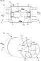
- Figure 2 shows a schematic top view of an embodiment of a heating system 10 with the first heating module 12 and the second heating module 28.
- the first heating module 12 has a first module housing 36.
- the second heating module 28 has a second module housing 38. In the example shown, the first heating module 12 and the second heating module 28 are directly connected to one another.
- first heating module 12 and the second heating module 28 can be connected to one another by means of an adapter device 40.
- Figure 3A shows the disconnected state of the two heating modules 12, 28.
- Fig. 2 shows the connected state when the first heating module 12 is connected in the direction of the arrow in Figure 3A has been plugged into the adapter device 40.
- the first heating module 12 and the second heating module 28 have suitable mechanical interfaces (or generally contact areas) for the removal or supply of air, so that they can be connected directly to one another.
- Figure 3B shows the possibility that an air flow connection in the form of a pipe or a hose 42 is possible between the first heating module 12 and the second heating module 28.
- the first heating module 12 has a pipe adapter 44 into which the pipe or hose 42 can be inserted and fastened.
- second heating module 28 has a blower device not visible in these figures. By means of the blower device, air is conveyed from the second heating module 28 to the first heating module 12. Furthermore, it should be noted that instead of the second heating module 28, only one blower device (without a heating function) could be connected to the first heating module, as shown in FIG Fig. 1 shown schematically and explained above.
- the second heating module 28 can, for example, be a heater that is operated with gas or diesel or electrically.
- the first heating module 12 is preferably an electrically operated heater.
- the second heating module 28 shown here has an air inlet opening 46 in its second module housing 38.
- the air inlet opening 46 is covered by a protective grille 48.
- Into the second Air sucked in from the heating module 28 is circulated within the second heating module 28 (by means of the invisible blower device) and heated (by means of an invisible gas burner), and then exits again at an air outlet opening 50.
- the second heating module 28 can also only be operated to circulate air without the air being heated therein.
- a gas connection 52 is provided on the second heating module 28.
- the second heating module 28 has an exhaust gas outlet 54, at which exhaust gases can exit after the combustion of gas or can be discharged via an exhaust gas line, not shown here.
- the first heating module 12 has an air inlet opening 56 and an air outlet opening 58 on its first module housing 36.
- the air inlet opening 56 is in the case of Fig. 2 or 3B by means of the adapter device 40 arranged directly opposite the air outlet opening 50 of the second heating module when the two heating modules are connected to one another.
- the hose or pipe 42 extends between the air outlet opening 50 of the second heating module 28 and the air inlet opening 56 of the first heating module 12.
- the pipe adapter 44 is arranged at the air inlet opening 56.
- the first heating module 12 has a protective grille 60 in the area of its air outlet opening 58.
- the heating system 10 can be operated in such a way that the blower device 14 ( Fig. 1 ) conveyed air is only heated by the first heating module 12.
- the heating system 10 can be operated in such a way that air conveyed by the blower device 14 is only heated by the second heating module 28.
- the first heating module 12 can be used as an additional or supplementary heater for the second heating module 28.
- the heating system 10 can be operated either with gas or with electricity or in combination.
- the operation of the first heating module 12 is particularly suitable when the habitable vehicle is connected to an external power connection.
- the control or regulation of the two heating modules can also be set up in such a way that the respective consumption of gas or electricity is optimized. This can be done in particular taking into account parameters such as the outside temperature, the current inside temperature, the indoor temperature to be achieved or the like.
- both heating modules are operated in such a way that they are coordinated with one another in such a way that a heating output of the heating system 10 is achieved which warms up the habitable room to a desired internal temperature within a minimal period of time.
- FIG 4 is the first heating module 12 with the off Fig. 3B known pipe or hose connection 42 shown as part of a heating system 10.
- the hose connection 42 is contacted via the pipe adapter 44 with the air inlet opening 56 of the first heating module 12.
- a further pipe adapter 44a is arranged instead of the protective grille 60.
- a further tubular or hose-shaped connecting line 62 is connected to this pipe adapter 44a.
- the pipe or hose 62 has a distributor element 64, from which the air flow can exit in different directions or can be forwarded if another pipe or hose-like connecting element should be connected to the distributor element 64.
- the connecting line 62 and/or the distribution element 64 can also be referred to as further components of the heating system, which are shown in the schematic Figure 1 are subsumed as a further component 20.
- an additional housing 66 is provided on the module housing 36 of the first heating module 12.
- the additional housing 66 serves to accommodate electronic components not visible in these figures, which are primarily set up to control the first heating module 12.
- the first heating module 12 that can be used in the heating system 10 is described in more detail. If the term “heating module” is used alone below, in the context of this application it always means the “first heating module” of the heating system. In this respect, the properties and features of the heating module 12 described below can also be understood as further developments for the first heating module 12 of the heating system 10 described above.
- FIG. 5 shows the heating module 12 in a perspective exploded view.
- the (first) module housing 36 has a lower half-shell 36a and an upper half-shell 36b.
- the two half-shells 36a, 36b can be connected to one another in a form-fitting manner.
- the upper half-shell 36b has a circumferential Spring 68 and the lower half-shell 36a has a groove 70.
- the two half-shells 36a, 36b are secured in the connected state by means of screws (not shown).
- corresponding screw openings 72a and 72b are also noted, which are provided in the respective half-shells 36a, 36b.
- FIG 5 The view is clear of the air outlet opening 58 of the first module housing 36.
- the module housing 36 has a substantially circular flange 74 in the area of the air outlet opening 58. This can be done on this flange 74 Figures 2 and 3 Protective grid 60 shown can be attached. Furthermore, the flange 74 can be used in the Figure 4 pipe adapter 44a shown can be connected.
- the air inlet opening 56 of the module housing 36 can be partially seen in the area of the lower half-shell 36a. Also visible at the air outlet opening 58 is an end face 124c of a displacer element, which will be described in more detail later, and which deflects air to a sensor device.
- An air guide element 76 is accommodated in the (first) module housing 36.
- the air guide element 76 forms a type of inner housing through which the air to be heated flows along a main flow direction SR.
- a pipe adapter 44 or 44a is shown as an example, which is in particular designed to accommodate a pipe or a hose 42 or 62 ( Fig. 4 ) to be connected to the (first) heating module 12.
- an additional housing 66 is arranged on the (first) module housing 36.
- the additional housing can also be formed by a lower half-shell 66a and an upper half-shell 66b.
- the two half-shells 66a, 66b of the additional housing 66 can also be connected to one another in a form-fitting manner.
- the upper half-shell 66b has a spring 78 and a groove 80 is provided on the lower half-shell.
- the additional housing 66 is designed to accommodate circuit boards 82, 84.
- the two circuit boards 82, 84 form a control device 86 of the (first) heating module 12.
- Two sockets 88 can be seen on the circuit board 84 as an example.
- connection 24, 26, 30 can be used for communication with other components of the heating system 10 (see Figure 1 ) can be connected.
- An electrical cable 90 is shown schematically and in simplified form between the two circuit boards 82, 84. This cable 90 serves in particular to power the (first) heating module 12 or one (or more) heating coils arranged therein as an exemplary embodiment of the heating element, which are not visible in the figure because they are accommodated in the air guide element 76.
- Figure 6 shows in one to Figure 5 Similar perspective exploded view of the air guide element 76.
- the air guide element 76 is formed in this example by a first guide section 92, a second guide section 94 and a third guide section 96.
- the first guide section 92 is arranged in the assembled state of the (first) heating module 12 in the area or, in relation to the flow direction SR, just behind the air inlet opening 56.
- the second guide section 94 is arranged in the assembled state of the (first) heating module 12 in the area or, in relation to the flow direction SR, just before the air outlet opening 58.
- the first guide section 92 has a plurality of deflection elements 98.
- the deflection elements 98 are arranged here along a circle and together form a deflection ring 100.
- the deflection elements 98 have a bent or curved shape relative to an axial direction of the air guide element 76 that is parallel to the flow direction SR.
- the deflection elements 98 can also be referred to as a type of turbine blades.
- the deflection elements 98 are firmly connected to the first guide section 92, in particular formed in one piece as an integral component.
- the second guide section 94 has a plurality of webs 102 which extend from radially outside to radially inside in relation to a radial direction RR.
- the webs 102 are firmly connected to the second guide section 94, in particular formed in one piece as an integral component.
- the end face 124c of the displacement element 124 for the sensor device 130 should also be noted here.
- the third guide section 96 is included between the first guide section 92 and the second guide section 94.
- the first guide section 92 and the second guide section 94 can be plugged onto the third guide section 96.
- the third guide section 96 has a substantially circular flow cross section.
- the circular shape has two opposing flattened sections 104.
- Corresponding flattened sections 106, 108 can also be seen on the first guide section 92 and the second guide section 94, respectively.
- the flattened sections 104, 106, 108 also serve as a kind of securing of the positive plug connection, so that the guide sections 92, 94, 96 cannot rotate relative to one another.
- the air guide element 76 is in Figure 7 shown in a longitudinal section, which corresponds approximately to section line VII-VII of the Figure 5 corresponds.
- the first guide section 92, the second guide section 94 and the third guide section 96 can be seen in the assembled state. Air enters the main flow direction SR Fig. 7 from the left into the first guide section 92 and flows through the air guide element 76 until it exits again at the second guide section 94.
- Two heating coils 110, 112 are arranged in the third guide section 96.
- the two heating coils 110, 112 are arranged one after the other in the flow direction SR or in the axial direction AR.
- the heating coils are attached to a lower flattened section 104 of the third guide section 96.
- Each heating coil 110, 112 has two electrical connections 114a, 114b or 116a, 116b arranged outside the third guide section 96.
- a respective fuse 118 is arranged in the area of each heating coil 110, 112. The fuses 118 serve in particular to prevent the heating coils 110, 112 from overheating.
- the deflection elements 98 on the first guide section 92 can also be seen.
- the deflection ring 100 has a central opening 120 through which air can also flow. Air that flows in in the area of the deflection elements 98 is directed in particular radially outwards, so that essentially the entire flow cross section formed by the third guide section 96 can be used. This is illustrated by the short arrows 122.
- a displacer element 124 with an end face 124c is also arranged in the flow cross section of the air guide element 76.
- the displacement element 124 is designed to displace the air radially outwards and the end face 124c also enables the return of the air to the sensor device 130. It has a side or surface 126 facing the flow direction SR, which is curved or curved .
- the side 126 facing the flow SR is spherical, in particular designed as a spherical cap or hemisphere, or as a paraboloid.
- the displacement element 124 serves as a cover for a receiving space 128 of a sensor device 130.
- the receiving space 128 (sensor receptacle) is provided in a central area of the second guide section 94.
- the displacement element 124 can be an integral part of the second guide section 94.
- the sensor device 130 is set up to detect the temperature of the heated air.
- the webs 102 of the second guide section 94 (see also the following Figure 10 ) have air guide channels 132, which are designed to direct heated air from the main flow towards the receiving space 128 and the sensor device 130 arranged therein.
- the sensor device 130 is therefore not exposed to the main flow of heated air, but rather measures the temperature of a part of the air branched off or removed from the main flow. This also ensures in particular that an average temperature is measured that corresponds as closely as possible to the temperature that the air has when it comes out of the (first) module housing 36 ( Fig. 2 to 5 ) exit.
- the displacement element 124 in particular its outside 134, and the inside 136 of the air guide element 76, in particular the third guide section 96, delimit an annular flow channel section 138.
- Fig. 8 shows one to the Figures 5 and 6 Similar perspective exploded view of the third guide section 96 and the heating coils 110 and 112 arranged therein. From the illustration it can be seen that the third guide section 96 can be formed by two essentially semicircular partial profiles 96a, 96b. Both partial profiles have respective flange sections 140a, 140b, on which the two partial profiles 96a, 96b can be connected to one another.
- Each heating coil 110, 112 has two essentially straight connecting sections 142.
- the connection section 142 is followed by a transition section 144.
- Starting from the transition section 144, several turns 146 can then be seen, which merge into one another in a spiral shape.
- the spiral-shaped turns 146 in particular those turns with the smallest radius or diameter, are connected radially on the inside by a transverse section 148 running along the axial direction AR.
- FIG 9 shows an alternative embodiment of the (first) heating module 12 in a perspective partial sectional view.
- the heating module 12 has a displacement element 224, which extends essentially over the entire length of the air guide element 76.
- the displacement element 224 has a central section 224a, which is directly connected to the first guide section 92 and the second guide section 94 is connected.
- a hemispherical cover element 224b is provided in the area of the first guide section 92.
- Opposite the cover element 224b is the end face 224c.
- the flow cross section of the air guide element 76 is annular over essentially the entire length.
- the annular flow channel 238 is delimited by the outside 234 of the displacement element 224 and the inside 236 of the air guide element 76.
- FIG. 9 An alternative arrangement of two heating coils 210, 212 can also be seen.
- the first heating coil 210 has several turns 246a following one another in a helical manner.
- the second heating coil 212 has several turns 246b following one another in a helical manner.
- the two heating coils 210, 212 are arranged along the axial direction AR in such a way that their turns 246a, 246b alternate.
- the respective turns 246a and 246b are designed such that their diameter increases along the flow direction.
- Figure 10 shows a perspective view of the second guide section 94. Reference is made to the third guide section 96 ( Figs. 6 and 7 ) facing side. As already mentioned, several webs 102 are arranged on the second guide section 94. In the present example, three webs 102 are shown. However, the number of webs 102 is not limited to three; only two webs can be provided or more than three. This illustration also shows the receiving space 128 for the sensor device 130, not shown here ( Figs. 6 and 7 ) visible. An air duct 132 is provided on each web 102 and is designed to redirect or branch off heated air in the direction of the receiving space 128. As a result, part of the air is diverted from different areas of the air flow and sent to the sensor device 130 ( Figs.
- the displacement element 124, 224 and the sensor device or sensor element 130 are located along the longitudinal axis of the first heating module 12. This axial arrangement also relates to the fuses 118 of the variant in FIG Figures 6 and 7 .
- Fig. 11 the first guide section 92 is shown with the deflection elements 98 arranged along a circle.
- the deflection elements 98 are connected to one another with a circular or ring-shaped base 97.
- the annular base 97 is also part of the deflection ring 100, which is formed by all deflection elements 98.
- the radially outer ring element 99 is connected to a circumferential sleeve 103 of the first guide section 92 by means of webs 101.
- the deflection elements 98 have a shovel-like profile. Radially on the outside, ring sector-shaped air passages 103 are formed between two adjacent webs 101.
- the first guide section 92 is preferably formed in one piece with the deflection elements; in particular, the first guide section 92 can be made as an injection-molded part made of plastic.
- the air passages 105 can also be closed by the components, the adapter device, the end region of a pipe, etc.
- a simplified guide section 192 is shown with deflection elements 198a and 198b arranged along two essentially concentric circles.
- Radially inner deflection elements 198a redirect incoming air in a different direction than the radially outer deflection elements 198b.
- the inner deflection elements 198a are arranged along an annular base 197a.
- the outer deflection elements 198b are arranged along an annular base 197b.
- the radially inner deflection elements 198a form a first deflection ring 100.
- the radially outer deflection elements 198b form a second deflection ring 300.
- guide section 192 for example, instead of one in the previous ones Figures 6 and 11 shown first guide section 92 can be used in a heating module 12.
- further radially outer structural configurations are omitted or not shown, even if corresponding adjustments or structural configurations may be required for installation in a heating module 12.
- FIG. 13 A simplified guide section 292 is shown with a deflection element 298 designed as a conical ring.
- the annular deflection element 298 is held by several webs 201 in a central or central area of the flow cross section. Due to the conical design of the annular deflection element 298, incoming air is displaced radially outwards. A free space or a recess 301 is provided inside the deflection element 298, through which air can flow in the axial direction essentially undisturbed.
- Guide section 192 shown can be used in a heating module 12.
- further radially outer structural configurations are omitted or not shown, even if corresponding adjustments or structural configurations may be required for installation in a heating module 12.
- the Figure 14 shows in the partial figures A) and B) two perspective and simplified representations of a displacement element 324, which is designed as a plate.
- the displacement element 324 is here, for example, attached to the second guide section 394 via radial struts 325.
- the exemplary embodiment shown is a flat and curvature-free plate. In alternative embodiments, these are concave or convex or possibly otherwise curved plates, for example in shape similar to that in Figure 6 or 7 Displacer element 124 shown.
- the displacer element 324 is designed here as a circular plate. However, it is also conceivable that the displacement element 324 be a polygonal plate, for example a hexagon, an octagon or the like.
- a sensor element 330 is shown schematically in the flow direction SR behind the displacement element 324.
- the position of the sensor element 330 is in particular such that it is in the recirculation area (indicated by curved arrows RG) of the displacer element 324.
- This design is intended in addition to the designs with the webs.
- the embodiment shown can be used, for example, on the air inlet opening 56 (see Fig. 3 to 5 ) or at the air outlet opening 58 (please refer Fig. 3 to 5 ) of the heating module can be arranged so that the temperature of the air supplied or removed can be measured.
- the Figure 15 shows in the partial figures A) and B) a simplified longitudinal sectional view and a simplified perspective partial sectional view of a displacement element 424 in the central region of the heating module or the air guide element 476 and thus in the region in which the supplied air is heated.
- the central cylindrical - here primarily tubular - section 424a is delimited by two covers 424b, 424c, which are each designed here as flat plates. However, the plates could also be curved.
- a sensor element 430 is also arranged in the cylindrical section 424a, which here, as in the other embodiments, is also located on the longitudinal axis LA.
- the middle section 424a is received at its axial ends in recesses 429b, 429c in the covers 424b, 424c.
- the recesses 429b, 429b can be designed, for example, as an annular groove.
- the covers 424b, 424c and the middle section 424a held by them are arranged in the air guide element 476 by means of struts 425.
- the air flows around the displacement element 424, in particular around the central sections 424a from the air inlet opening 56 ( Fig. 3 to 5 ) to the air outlet opening 58 ( Fig. 3 to 5 ) of the heating module.
- the air in the recess or in the interior 424d of the displacement element 424 or the central section 424a flows in the opposite direction UR, i.e. back towards the air inlet opening 56. Therefore, there are open feed areas 427 and discharge areas at both ends of the cylindrical section 424a 427 for the air.
- the air flow counter to the main flow direction SR is in the Figure 15A illustrated by corresponding arrows UR.
- the air guide element 476 of the Figure 15 has a substantially symmetrical structure with respect to a central plane which orthogonally intersects the longitudinal axis LA. Accordingly, a heating module with such a design of the air guide element 476 can be installed in any orientation in the flow path of a heating system.
- FIG 16A shows the heating module 12 in a simplified perspective view, as already shown in the Figures 2 to 9 has been presented.
- a bent or curved pipe piece 41 is attached to the air inlet opening 56.
- the pipe or the pipe bend 41 is already in the Fig. 5
- Pipe adapter 44 shown is connected to the module housing 36.
- a curved or bent hose (not shown) to the air inlet opening 56, in particular using the pipe adapter 44 or an adapter that may be adapted for hose connections.
- the pipe bend 41 is an exemplary embodiment of an air duct component that serves to homogenize the flow of air that is supplied to the first heating module 12.
- the curved or curved pipe section 41 serves in particular to supply air conveyed by a blower (not shown) to the heating module 12 in a flow that is as homogeneous as possible. If an air flow that is as homogeneous as possible is supplied, the effectiveness of the heating module 12 is increased.
- Figure 16B shows a sectional view (longitudinal section) through the pipe section 41 and the transition into the module housing 36.
- Several ribs or curved sections 43 are formed in the pipe bend 41. These ribs or arch sections 43 serve to guide air and are examples of deflection elements inside the air guide component.
- Four ribs or arch sections 43 are shown as an example, resulting in five paths 45 in which air can flow. Through the ribs or arch sections 43, air in the tracks 45 can be guided specifically in the direction of the deflection elements 98. In other words, it can also be said that the deflection elements 98 are lengthened by the ribs or arch sections 43.
- the pipe adapter 44 has an upstream first section 44b with a first inner diameter IM1.
- a second section 44c with a second inner diameter IM2 follows downstream.
- the first inside diameter IM1 is larger than the second inside diameter.
- the transition between the first section 44b and the second section 44c is formed by a stop surface 47.
- a (straight) pipe or a hose or the curved pipe section 41 can rest on this stop surface 47.
- the outer diameter of the pipe section 41 is matched to the inner diameter IM1 of the first section 44b.
- Figure 16C shows the pipe adapter in a simplified perspective view.
- the two sections 44b and 44c can be seen.
- the stop surface 47 is along the inner circumference of the two sections 44b, 44c visible.
- Locking elements 49 can be provided on the first section 44b, in which a pipe or hose to be connected is accommodated.
- the illustration shows two latching elements 49 as an example, the number of latching elements 49 not being limited to two, but can also be larger. It goes without saying that corresponding counterparts are also present on the pipe or hose, in particular locking recesses into which the locking elements 49 can engage.
- guide recesses 51 can also be arranged on the first section 44b. Corresponding guide elements that are present on the pipe to be connected (eg pipe bend 41) or on the hose to be connected can be inserted into such guide recesses 51.
- the pipe adapter 44 can be connected to the module housing 12, for example, by several screw connections 53.
- interlocking or corresponding connecting structures on the pipe adapter 44 and on the pipe or pipe bend 41 to be connected can also be designed differently than the locking elements 49 and guide recesses 51 shown here.
- the locking elements and corresponding snap-in receptacles could be arranged interchangeably, the same applies for guide recesses and corresponding guide elements.
- the pipe bend 41 is free of curvature and is therefore equal to a straight piece of pipe.
- the ribs or arch sections 43 of this embodiment of the pipe bend 41 are therefore also free of curvature in this embodiment.
- the ones here with reference to the Figures 1 to 4 presented heating system 10 or that here with reference to the Figures 5 to 16 presented (first) heating module 12 enable a heating system to be set up or an existing heating arrangement to be expanded in a habitable vehicle in a flexible manner.
- the (first) heating module 12 is designed as a compact electric heater, which can be easily connected to air-conducting elements in such a way that air can be heated by means of the (first) heating module 12.
- the (first) heating module 12 does not have its own (integrated) fan, but rather is connected to a separate fan, which can in particular also be part of an existing heater (second heating module 28).
Landscapes
- Engineering & Computer Science (AREA)
- Physics & Mathematics (AREA)
- Thermal Sciences (AREA)
- Mechanical Engineering (AREA)
- Chemical & Material Sciences (AREA)
- Combustion & Propulsion (AREA)
- General Engineering & Computer Science (AREA)
- Air-Conditioning For Vehicles (AREA)
- Direct Air Heating By Heater Or Combustion Gas (AREA)
Description
- Die Erfindung betrifft ein Heizmodul für eine Heizanlage eines bewohnbaren Fahrzeugs.
- Unter dem Begriff bewohnbares Fahrzeug werden alle Arten von angetriebenen oder nicht angetriebenen Fahrzeugen verstanden, in denen eine Person oder mehrere Personen auch wohnen kann bzw. können. Bei solchen bewohnbaren Fahrzeugen handelt es sich insbesondere um Wohnmobile, Wohnwagen oder Schiffe bzw. Boote.
- Bisherige Heizanlagen für bewohnbare Fahrzeuge basieren auf dem Prinzip, dass von einer in der Regel zentralen Heizung aus, erwärmte Luft in den bewohnbaren Raum austritt bzw. über ein System von Rohren oder Schläuchen an unterschiedliche Stellen im bewohnbaren Raum verteilt wird. Üblicherweise sind in dieser Heizung ein Heizaggregat (elektrisch oder mit Gas betrieben) und ein Gebläse untergebracht. Um eine entsprechende Heizleistung gewährleisten zu können, sind für einen größeren bewohnbaren Raum entsprechend auch leistungsstärkere und damit in der Regel von ihren Dimensionen her größere Heizungen erforderlich.
- Aus der
DE 10 2013 001 441 A1 ist eine Heizungsanordnung zum Aufheizen eines die Heizungsanordnung durchströmenden Mediums bekannt, mit einem Gehäuse mit einem ersten und einem zweiten Gehäuseteil. In dem Gehäuse ist eine Heizbaugruppe angeordnet. - Die
DE 10 2010 060 446 A1 offenbart einen elektrischen Heizer mit einem ein Fluid führenden Gehäuse, in dem ein wendelförmiger Heizkörper aufgenommen ist. - Der Erfindung liegt die Aufgabe zu Grunde, ein flexibel einsetzbares Heizmodul für eine Heizanlage bereitzustellen, das einen geringen Platzbedarf aufweist und funktionstechnisch in die Heizanlage integrierbar ist.
- Diese Aufgabe wird gelöst durch ein elektrisches Heizmodul gemäß dem unabhängigen Anspruch 1. Mögliche Ausgestaltungen des Heizmoduls sind in den abhängigen Ansprüchen enthalten.
- Es wird ein Heizmodul für eine Heizanlage für ein bewohnbares Fahrzeug bereitgestellt mit:
- einem Modulgehäuse mit einer Lufteintrittsöffnung und einer Luftaustrittsöffnung,
- einem im Modulgehäuse aufgenommenen Luftführungselement, das mehrere Führungsabschnitte aufweist und das mit der Lufteintrittsöffnung und der Luftaustrittsöffnung verbunden ist, und
- wenigstens einem Heizelement, wobei das Heizelement dazu eingerichtet ist, Luft, die von der Lufteintrittsöffnung zur Luftaustrittsöffnung strömt, zu erwärmen.
- Das Heizmodul erlaubt in einer Ausgestaltung die Verbindung mit weiteren Komponenten, sodass sich insgesamt eine Heizanlage ergibt.
- Ein derartiges Heizmodul, das insbesondere keine eigene Gebläsevorrichtung aufweist, kann flexibel in einer Heizanlage eingebaut und eingesetzt werden. Dabei ist der Platzbedarf des Heizmoduls sehr gering.
- Die Lufteintrittsöffnung kann dazu eingerichtet sein, mit einer von dem Heizmodul gesonderten Gebläsevorrichtung verbindbar zu sein.
- In einer alternativen Ausgestaltung handelt es sich bei dem Heizmodul um eine eigenständige Heizung. Hierfür verfügt das Heizmodul in einer Ausgestaltung vorzugsweise über eine Gebläsevorrichtung.
- Das Heizmodul weist eine Sensorvorrichtung auf, die dazu eingerichtet ist, die Temperatur der das Heizmodul durchströmenden Luft zu erfassen.
- Ferner kann das Heizmodul eine Steuervorrichtung aufweisen, die dazu eingerichtet ist, das Heizmodul anzusteuern. Dabei kann die Steuervorrichtung eine Schnittstelle aufweisen, die dazu eingerichtet ist, eine Kommunikationsverbindung zu einem von dem Heizmodul gesonderten Gerät bereitzustellen.
- Durch die Steuervorrichtung mit ihrer Schnittstelle kann das Heizmodul auch steuertechnisch in eine Heizanlage integriert werden.
- Die Sensorvorrichtung kann bezogen auf einen Strömungsquerschnitt des Heizmoduls in einem zentralen Bereich eines Luftführungselements angeordnet sein. Hierdurch wird insbesondere der Bereich eines erwärmten Luftstroms gemessen, in dem verteilt über den Strömungsquerschnitt üblicherweise die höchste Temperatur herrscht, sodass die Abgabe von zu stark erwärmter Luft zuverlässig ausgeschlossen werden kann. Dies ermöglicht insbesondere, die Gefahr von Hitzeschäden an Bauteilen des Fahrzeugs oder von Verletzungen von Personen zu verhindern.
- Eine Abweichung der Position der Sensorvorrichtung relativ zu einer Mitte des Strömungsquerschnitts kann kleiner oder gleich 20% eines Durchmessers des Luftführungselements betragen. Ferner kann die Sensorvorrichtung entlang einer - vorzugsweise zentrischen - Längsachse des Luftführungselements angeordnet sein. Die im Wesentlichen mittige Anordnung bezüglich des Querschnitts bzw. entlang der Längsachse dient dem Zweck, dass das Heizmodul mit unterschiedlichen Einbaulagen (damit auch unterschiedlichen Drehlagen relativ zur Erdanziehung) verbaut werden kann, wobei die Sensorvorrichtung jeweils zuverlässig misst. Wäre die Sensorvorrichtung beispielsweise nicht mittig, sondern näher an einer Wandung angeordnet, so würde die Sensorvorrichtung gegebenenfalls zeitlich später reagieren, wenn die Wandung weiter vom Erdschwerefeld entfernt und die Luft somit "tiefer" unten stehen würde.
- In einer Ausgestaltung befindet sich die Sensorvorrichtung innerhalb eines Rezirkulationsgebiets eines Verdrängerelements. Das Verdrängerelement verdrängt somit die Luft radial nach außen und die Sensorvorrichtung befindet sich in dem Bereich, in welchem die verdrängte Luft wieder zurückströmt.
- In einer ergänzenden oder alternativen Ausgestaltung befindet sich die Sensorvorrichtung in einem Querschnitt des Verdrängerelements oder in einer Projektion des Querschnitts, also z. B. in der geometrischen Verlängerung des Querschnitts. Insbesondere befindet sich die Sensorvorrichtung in einer Luftströmungsrichtung hinter dem Verdrängerelement.
- Das Verdrängerelement kann so ausgestaltet sein, dass es Luft um die Sensorvorrichtung leitet, sodass durch das Verdrängerelement umgelenkte Luft die Sensorvorrichtung erreicht. Weiterhin kann vorgesehen sein, dass nur die umgelenkt Luft die Sensorvorrichtung erreicht. Hierdurch wird somit ein direkter Kontakt der Sensorvorrichtung mit der eigentlichen Luftströmung vermieden.
- Das Luftführungselement weist die folgenden Teile bzw. Führungsabschnitte auf:
- einen ersten Führungsabschnitt, der mit der Lufteintrittsöffnung verbunden ist,
- einen zweiten Führungsabschnitt, der mit der Luftaustrittsöffnung verbunden ist, und
- einen dritten Führungsabschnitt, der zwischen dem ersten und dem zweiten Führungsabschnitt aufgenommen und mit diesen verbunden ist.
- Das Luftführungselement bildet sozusagen ein Innengehäuse des Modulgehäuses.
- Dabei kann das Luftführungselement in Bezug auf das Strömen von Luft optimiert werden, insbesondere hinsichtlich seiner Form bzw. seines Querschnitts. Das Luftführungselement kann im Querschnitt insbesondere kreisförmig oder ellipsenförmig ausgebildet sein. Das Modulgehäuse kann hiervon unabhängig eine andere äußere Gestaltung aufweisen, insbesondere kann das Modulgehäuse im Wesentlichen ebene Außenflächen aufweisen, die den Einbau entlang von in der Regel ebenen Fahrzeugstrukturen, wie Wänden, Verkleidungen, Boden und dergleichen vereinfacht.
- Die Führungsabschnitte können als rohrartige Bauteile ausgebildet sein. Dabei kann jeder Führungsabschnitt ein in sich stabiles Bauteil sein. Die Führungsabschnitte können an ihren betreffenden Enden miteinander verbunden werden, wobei die Führungsabschnitte insbesondere so ausgebildet werden können, dass der erste Führungsabschnitt und der zweite Führungsabschnitt mittels einer Formschlussverbindung, wie etwa Steckverbindung oder Rastverbindung, mit dem dritten Führungsabschnitt gekoppelt sind. Denkbar sind aber auch andere Verbindungsarten wie etwa eine Gewindeverbindung, bei der an einem Führungsabschnitt ein kurzes Außengewinde vorgesehen ist und an dem anderen Führungsabschnitt ein korrespondierendes Innengewinde. Ferner können die Führungsabschnitt bei Bedarf auch materialschlüssig miteinander verbunden sein, etwa durch eine Verklebung.
- Das Heizelement des Heizmoduls ist in Strömungsrichtung hinter dem ersten Führungsabschnitt angeordnet. Erfindungsgemäß ist das Heizelement in dem dritten Führungsabschnitt aufgenommen. Das Heizmodul kann somit in der Regel sehr einfach und platzsparend eingebaut werden, da lediglich ein Anschluss an eine Energiequelle, beispielsweise Stromanschluss, vorgesehen werden muss. Ferner kann das Heizmodul auch einfach in eine bestehende Heizanlage integriert werden. Dabei ist es besonders vorteilhaft, dass das Heizmodul passiv von Luft durchströmt wird, d.h. das Heizmodul selbst verfügt nicht über ein eingebautes Gebläse.
- Gemäß einer Ausgestaltung kann das Luftführungselement in Bezug auf eine zur Strömungsrichtung orthogonalen Mittelebene im Wesentlichen symmetrisch ausgebildet ist, sodass das Heizmodul beim Einbau in eine Heizanlage beliebig ausgerichtet sein kann. Dabei können insbesondere der erste Führungsabschnitt und der zweite Führungsabschnitt im Wesentlichen gleichartig oder identisch ausgebildet sein.
- Ein Strömungskanal des Luftführungselements kann querschnittssymmetrisch ausgebildet sein. Dies ermöglicht insbesondere ein beliebig verdrehtes Einbauen des Heizmoduls, insbesondere verdreht in Relation zu Rohr- oder Schlauchanschlüssen oder verdreht in Relation zu einem Strukturbauteil des Fahrzeugs, wie etwa eine Wand oder ein Boden.
- Bei dem Heizmodul ist die Sensorvorrichtung in einer Sensoraufnahme angeordnet, die durch mehrere Stege gehalten ist, wobei die Stege an dem zweiten Führungsabschnitt oder an dem ersten Führungsabschnitt vorgesehen sind und sich im Wesentlichen in radialer Richtung von der Sensoraufnahme aus erstrecken. Dabei wird mit der Erstreckung in radialer Richtung insbesondere beschrieben, dass die Stege von radial innen nach radial außen verlaufen bezogen auf einen beispielsweise kreisförmigen Führungsabschnitt. Der Begriff Erstreckung in radialer Richtung soll aber nicht definieren, ob der Steg exakt geradlinig dem Radius folgt oder ob der Steg ggf. leicht geneigt zum Radius oder bogenförmig bzw. geschwungen ausgebildet ist.
- Einige oder alle Stege weisen einen Luftführungskanal auf, der so ausgebildet ist, durchströmende Luft in Richtung der Sensorvorrichtung zu leiten. Hierdurch kann aus unterschiedlichen Bereichen des insbesondere erwärmten Luftstroms Luft zum Sensor geführt werden. Im Bereich des Sensors wird die Luft aus den unterschiedlichen Strömungsbereichen gemischt, sodass gegebenenfalls Temperaturunterschiede in den verschiedenen Strömungsbereichen etwas ausgeglichen werden. Entsprechend kann hierdurch gewährleistet werden, dass die Sensorvorrichtung eine gemittelte Temperatur des erwärmten Luftstroms misst bzw. erfasst.
- Einige oder alle Stege können aus einem temperaturleitfähigen Material bestehen. Vorzugsweise hat das verwendete Material eine Wärmeleitfähigkeit größer oder gleich 15 W/(m * K). Denkbar ist beispielsweise, dass die Stege als Kupferstege ausgebildet sind, die eine Art Stern bilden.
- Die Sensorvorrichtung kann im dritten Führungsabschnitt angeordnet sein, wobei ein Steg die Sensorvorrichtung hält.
- Ferner kann die Sensorvorrichtung als Sicherung - vorzugsweise als Schmelzsicherung - ausgebildet sein, die auf das Überschreiten einer Temperatur reagiert.
- Die Sensorvorrichtung kann mindestens zwei entlang einer Längsachse des Luftführungselements axial voneinander beabstandete Temperatur-Sicherungen aufweisen.
- In einer Ausgestaltung verfügt das Heizelement über mehrere separate Heizkomponenten, z. B. separate Heizwendeln. Jeder der Heizkomponente ist dabei eine Temperatur-Sicherung zugeordnet.
- Das Heizmodul kann ein Verdrängerelement aufweisen, das dazu eingerichtet ist, durchströmende Luft nach radial außen zu verdrängen. Dabei kann das Verdrängerelement mit der Sensoraufnahme verbunden sein. Ferner kann das Verdrängerelement dazu eingerichtet sein, den Hauptstrom von erwärmter Luft um die Sensorvorrichtung zu leiten. Durch das Verdrängerelement wird gewährleistet, dass die Sensorvorrichtung nicht direkt bzw. unmittelbar mit dem Hauptstrom der erwärmten Luft in Kontakt kommt. Vielmehr wird die erwärmte Luft zunächst um das Verdrängerelement und die Sensorvorrichtung herumgeführt und anschließend mittels der oben erwähnten Luftführungskanälen in den Stegen zur Sensorvorrichtung geleitet. Dabei strömt die umgeleitete Luft im Wesentlichen von radial außen nach radial innen zur Sensorvorrichtung. Die Sensorvorrichtung kann in Bezug auf die Luftführungskanäle in den Stegen bezogen auf die Hauptströmungsrichtung auch stromaufwärts angeordnet sein. Hierdurch kann die Durchmischung von Luft, deren Temperatur erfasst wird, noch verbessert werden.
- In einer Ausgestaltung befindet sich die Sensorvorrichtung in dem Rezirkulationsgebiet hinter einem Verdrängerelement. Das Verdrängerelement verdrängt somit die Luft nach radial außen und in dem Gebiet, in welchen die Luft wieder zurückströmt, befindet sich die Sensorvorrichtung, sodass in diesem Gebiet auch die Temperaturmessung stattfindet.
- Das Verdrängerelement kann auch eine durchgehende Aussparung zum Führen von Luft aufweisen. In einer Ausgestaltung wird beispielsweise die Luft in der Aussparung entgegen der Strömungsrichtung im Strömungskanal - also von der Lufteintrittsöffnung zur Luftaustrittsöffnung - und damit gleichsam zurück geführt. Die Luft in der Aussparung strömt somit von der Richtung der Luftaustrittsöffnung in die Richtung der Lufteintrittsöffnung. In einer Ausgestaltung befindet sich eine Sensorvorrichtung innerhalb der Aussparung.
- Eine Außenseite des Verdrängerelements und die Innenseite des Luftführungselements können einen ringförmigen Strömungskanalabschnitt begrenzen. Dabei kann insbesondere durch die Dimensionierung des Verdrängerelements Einfluss auf die Ausgestaltung des ringförmigen Strömungsquerschnitts genommen werden. Dabei kann durch eine Verengung des Strömungsquerschnitts auch eine Art Düsenwirkung erzeugt werden, sodass die erwärmte Luft in Richtung der Luftaustrittsöffnung etwas beschleunigt wird.
- Das Verdrängerelement kann in Strömungsrichtung zwischen der Heizwendel und der Luftaustrittsöffnung angeordnet sein. Das heißt, dass das Verdrängerelement nur in einem Teil des Strömungsquerschnitts des Heizmoduls wirksam ist. Insbesondere kann das Verdrängerelement als halbkugelförmige oder paraboloidförmige Abdeckung ausgeführt sein. Eine solche Abdeckung kann stromaufwärts der Sensorvorrichtung angeordnet sein und die Sensorvorrichtung vor der direkten Luftströmung schützen.
- Alternativ hierzu kann das Verdrängerelement in Strömungsrichtung zwischen der Lufteintrittsöffnung und der Luftaustrittsöffnung angeordnet sein und von Windungen der Heizwendel oder allgemein den aktiven Komponenten eines Heizelements umgeben sein. In einer solchen Ausgestaltung erstreckt sich das Verdrängerelement im Wesentlichen über die gesamte Länge des Luftführungselements, insbesondere erstreckt es sich über die gesamte Länge des dritten Führungsabschnitts. Dabei ist der Strömungsquerschnitt über beinahe die gesamte Länge des Heizmoduls ringförmig ausgebildet.
- Das Heizelement kann als elektrisches Heizelement ausgestaltet sein. Dabei kann das Heizelement wenigstens eine Heizwendel mit mehreren Windungen aufweisen.
- Das Heizmodul bzw. das elektrische Heizelement kann zwei Heizwendeln aufweisen, die in Strömungsrichtung nacheinander angeordnet sind. Die beiden Heizwendeln können bevorzugt einzeln angesteuert werden. Alternativ werden beide Heizwendeln gleich angesteuert. Das Vorsehen von zwei Heizwendeln ermöglicht insbesondere einen zweistufigen Betrieb des Heizmoduls. Dabei kann bei einer ersten Stufe nur eine Heizwendel aufgeheizt werden. Bei einer zweiten Stufe werden beide Heizwendeln von Strom durchflossen und erhitzt.
- Alternativ zu einer sequentiellen Anordnung von zwei Heizwendeln können zwei Heizwendeln auch so angeordnet sein, dass in Strömungsrichtung wiederholt auf eine Windung der einen Heizwendel eine Windung der anderen Heizwendel folgt. In einer solchen Ausgestaltung wechseln sich also die Windungen der beiden Heizwendeln ab. Anders ausgedrückt kann man auch sagen, dass sich die Windungen in Strömungsrichtung überlagern bzw. ineinander verschlungen sind. Auch bei dieser Ausgestaltung ist es möglich, den oben beschriebenen zweistufigen Betrieb zu ermöglichen.
- Bei dem Heizmodul können in Strömungsrichtung aufeinander folgende Windungen der gleichen Heizwendel einen sich verändernden Durchmesser aufweisen. Insbesondere kann der Durchmesser von einer Windung zur nächsten (benachbarten) Windung größer oder kleiner werden. Hierdurch kann die Wärmeübertragung auf die durchströmende Luft beeinflusst und optimiert werden. In einer Ausgestaltung ändert sich der Durchmesser stetig in einer Richtung.
- Die Steuervorrichtung des Heizmoduls kann in einem am Modulgehäuse angeordneten Zusatzgehäuse untergebracht sein. Dabei kann das Zusatzgehäuse dazu eingerichtet sein, eine zur Steuervorrichtung zugehörige Platine aufzunehmen. Das Zusatzgehäuse ermöglicht einen leichten Zugang zur Steuervorrichtung, um gegebenenfalls deren Austausch oder Konfiguration einfach vornehmen zu können. Ferner kann das Zusatzgehäuse mit ausreichend Lüftungsschlitzen versehen sein, um ein Überhitzen der Steuervorrichtung vermeiden zu können.
- Um eine kompakte Bauweise des Heizmoduls zu unterstützen, kann das Zusatzgehäuse so ausgebildet sein, dass es mit einer Außenseite des Modulgehäuses einen Aufnahmeraum für die Steuervorrichtung begrenzt. Dabei wird die Steuervorrichtung also in einem Raum aufgenommen, der von einer Außenseite des Modulgehäuses und im Übrigen vom Zusatzgehäuse gebildet wird. Das Zusatzgehäuse kann dabei auf das Modulgehäuse aufschiebbar oder aufsteckbar sein.
- Das Heizmodul kann mindestens ein Umlenkelement aufweisen, das an einem Führungsabschnitt angeordnet ist, der mit der Lufteintrittsöffnung oder der Luftaustrittsöffnung verbunden ist, wobei das Umlenkelement als ein von der Luft durchströmter Ring ausgestaltet ist. Dabei kann das als Ring ausgestaltete Umlenkelement einen in Strömungsrichtung sich ändernden Innendurchmesser aufweisen. Beispielsweise kann der Ring konisch ausgebildet sein, insbesondere sich in Strömungsrichtung konisch aufweiten.
- Das Heizmodul kann mehrere Umlenkelemente aufweisen, die an einem Führungsabschnitt angeordnet sind, der mit der Lufteintrittsöffnung oder der Luftaustrittsöffnung verbunden ist. Dabei können die Umlenkelemente eine konstante relative Position zu dem Führungsabschnitt aufweisen. Die Umlenkelemente werden somit in einer Ausgestaltung nicht relativ zum Modulgehäuse bewegt, sondern sind statisch fixiert. Ferner können die Umlenkelemente entlang eines Kreises angeordnet sein, sodass ein Umlenkkranz gebildet ist. Die Umlenkelemente dienen insbesondere dazu, die geförderte Luft im Heizmodul so zu verteilen bzw. strömen zu lassen, dass eine optimale Wärmeübertragung im Bereich der Heizwendel erfolgen kann. Ferner führen die Umlenkelemente zu einer verbesserten Durchmischung der beim Heizmodul ankommenden Luft und zu einer anschließend gleichmäßigeren Erwärmung.
- Die Umlenkelemente können entlang zweier Kreise angeordnet sein, sodass bezogen auf die Radialrichtung ein innerer Umlenkkranz und einen äußerer Umlenckranz gebildet sind. Dabei kann der innere Umlenkkranz Umlenkelemente aufweisen, die sich von den Umlenkelementen des äußeren Umlenkkranzes in Bezug auf die Umlenkrichtung der Luftströmung unterscheiden. Hierdurch kann insbesondere das Einströmen von Luft in das Heizmodul optimiert werden.
- Das als Ring ausgestaltete Umlenkelement kann auch als Träger von in dem Kreis angeordneten Umlenkelementen fungieren.
- Das Umlenkelement oder die mehreren Umlenkelemente können in einer Adaptervorrichtung angeordnet sein, die reversibel mit der Lufteintrittsöffnung des Modulgehäuses verbindbar ist. Hierdurch kann die Umlenkung oder die Messung somit auch durch Komponenten geschehen, die durch den Adapter aufsteckbar sind. Daher ließen sich z. B. zwei Heizeinheiten hintereinander stecken und am Ein- und Ausgang würden jeweils die Adapter angebracht werden.
- Ferner kann das Umlenkelement oder die mehreren Umlenkelemente einen mittigen Abschnitt umgeben, der eine direkte axiale Richtströmung erlaubt. Ein solcher mittiger Abschnitt würde in Bezug auf den Strömungsquerschnitt eine freie Aussparung bilden, durch die Luft im Wesentlichen ungehindert strömen kann.
- Je nach Ausgestaltung kann die Adaptervorrichtung dem Anschluss von beispielsweise Komponenten oder Rohren an das Heizmodul dienen. In anderen Ausgestaltung kann die Adaptervorrichtung auch über Bauteile verfügen, die eine zusätzliche Funktion übernehmen. Dies ist beispielsweise eine Homogenisierung des Luftstroms über wenigstens ein Umlenkelement und/oder das Ermitteln einer Temperatur, wobei über wenigstens ein Verdrängerelement eine Mischung von unterschiedlichen Temperaturfeldern bewirkt wird. Diese Adaptervorrichtungen mit einer zusätzlichen Funktionalität erlauben beispielsweise den modularen Zusammenbau des Heizmoduls oder einer Kombination von mehreren Heizmodulen.
- Das Vorsehen von Umlenkelementen im Bereich der Lufteintrittsöffnung bzw. im Bereich des ersten Führungsabschnitts des Luftführungselements hat auch den Vorteil, dass das Heizmodul mit unterschiedlichen vorgeschalteten Gebläsevorrichtungen oder sonstigen Anlagekomponenten gekoppelt werden kann. Durch die Umlenkelemente wird zum Heizmodul geförderte Luft in jedem Fall so geleitet bzw. umgelenkt, dass eine für das Heizmodul und das Erwärmen der Luft verbesserte Luftströmung im Luftführungselement erzeugt werden kann.
- In einer Ausgestaltung ist wenigstens eine Luftführungskomponente - vorzugsweise in Form eines Rohrbogens - für eine Homogenisierung einer Strömung einer in der Luftführungskomponente geführten Luft vorhanden. In dieser Ausgestaltung wird beispielsweise die Funktion der Homogenisierung der Luftströmung, wie sie im ersten Führungsabschnitt erfolgt, nach außen in den Bereich der Luftführungskomponente hinein verlängert. Die Homogenisierung der Luftströmung - insbesondere über den Strömungsquerschnitt - dient wiederum dem Zweck, dass das Erhitzen der Luft effektiver erfolgt.
- In einer Ausgestaltung kann die Luftführungskomponente über wenigstens einen Rohrbogen mit Bogenabschnitten verfügen. Die Bogenabschnitte begrenzen dabei Bahnen in dem Rohrbogen. Weiterhin dienen die Bahnen der Führung von Luft. Der Rohrbogen kann dabei gestreckt ausgeführt sein oder einen Winkel umfassen.
- Der Rohrbogen als ein Ausführungsbeispiel für die Luftführungskomponente dient allgemein der Erzeugung einer im Wesentlichen gleichmäßigen Luftströmung, indem ein Luftstrom, der in den Rohrbogen eintritt, gleichsam aufgeteilt und durch die einzelnen Bahnen geführt wird.
- Weiterhin kann in einer weiteren Ausgestaltung die Luftführungskomponente mit der Lufteintrittsöffnung oder der Luftaustrittsöffnung verbindbar oder verbunden sein.
- Das erste Heizmodul kann in einer Ausgestaltung sowohl unmittelbar als auch über eine Adaptervorrichtung mit mindestens einer separaten Entität - beispielsweise einer Gebläsevorrichtung oder einer allgemeinen Anlagenkomponente oder einem Rohr oder einem Schlauch oder einem Rohrbogen - oder mit mindestens zwei unterschiedlichen separaten Entitäten verbindbar sein, sodass eine Umlenkung von Luft in einem Führungsabschnitt des ersten Heizmoduls und in der unmittelbar oder über die Adaptervorrichtung mit dem ersten Heizmodul verbundenen Entität stattfindet. Als Teil der Heizanlage ist das erste Heizmodul entsprechend mit der separaten Entität verbunden. Das erste Heizmodul oder speziell das Gehäuse des ersten Heizmoduls kann somit derartig ausgestaltet sein, dass die Lufteintrittsöffnung und/oder die Luftaustrittsöffnung es erlaubt, dass - je nach Anwendung des Heizmoduls - eine unmittelbare oder eine mittelbare Verbindung mit einer separaten Entität vorgenommen wird. In einer Erweiterung kann auch eine solche mittelbare bzw. unmittelbare Verbindung mit zwei unterschiedlichen Entitäten (z. B. einer Vorrichtung mit Gebläse und einem Rohr) stattfinden. Die jeweilige Öffnung erlaubt also einen unmittelbaren Verbund und eine Verbindung über eine Adaptervorrichtung. Die separate Entität ist beispielsweise eine Gebläsevorrichtung oder eine sonstige, ggf. aktive Anlagenkomponente (z. B. eine Heizung oder eine Klimaanlage). Alternativ kann die separate Entität jedoch auch hauptsächlich der Führung von Luft dienen, insofern es sich um ein Rohr oder um einen Schlauch handelt. Die Verbindung soll dabei derartig sein und verfügt das erste Heizmodul dabei über eine solche Beschaffenheit, dass die Umlenkung der Luft - insbesondere für den Zweck der Homogenisierung der Luft - sowohl in einem Führungsabschnitt des ersten Heizmoduls (insbesondere dem ersten oder zweiten Führungsabschnitt) als auch in der angeschlossenen Entität stattfindet. In dieser Ausgestaltung wird somit eine separate Komponente oder ein separates Bauteil für eine Funktion des Heizmoduls eingebunden und verwendet, sodass die Funktion der Umlenkung bzw. Homogenisierung der Luft aus dem ersten Heizmodul herausgeführt wird.
- Das oben beschriebene Heizmodul kann in einer nachfolgend beschriebenen Heizanlage als erstes Heizmodul eingesetzt werden. Sofern nachfolgend der Begriff "Heizmodul" alleine verwendet wird, ist er im Zusammenhang mit der Beschreibung der Heizanlage als "erstes Heizmodul" zu verstehen. Insoweit werden mit den Begriffen "Heizmodul" alleine und "erstes Heizmodul" die gleichen Teile beschrieben, wohingegen der Begriff "zweites Heizmodul" ein anderes Bauteil beschreibt. Die Heizanlage kann die nachfolgend aufgeführten Merkmale aufweisen.
- Eine Heizanlage für ein bewohnbares Fahrzeug kann bereitgestellt werden mit:
- einem ersten Heizmodul, das in einem ersten Modulgehäuse aufgenommen ist, wobei das erste Heizmodul eine Lufteintrittsöffnung und eine Luftaustrittsöffnung aufweist,
- einer von dem ersten Heizmodul gesonderten Gebläsevorrichtung, die in einem zweiten Modulgehäuse aufgenommen ist,
- wobei die Gebläsevorrichtung und das erste Heizmodul mittels einer Verbindungsanordnung luftströmungstechnisch miteinander verbunden sind, und
- wobei die Gebläsevorrichtung relativ zu dem ersten Heizmodul deart angeordnet ist, dass von der Gebläsevorrichtung geförderte Luft bei der Lufteintrittsöffnung in das erste Heizmodul eintritt, das erste Heizmodul durchströmt und bei der Luftaustrittsöffnung das erste Heizmodul wieder verlässt.
- Bei der Gebläsevorrichtung kann es sich um eine eigenständige Gebläsevorrichtung oder um einen Teil einer Heizeinheit oder einer Klimaanlageneinheit handeln.
- Bei einer solchen Heizanlage sind die einzelnen Komponenten als Module verfügbar und können je nach verfügbarem Bauraum an unterschiedlichen Stellen eingebaut werden.
- Die Gebläsevorrichtung kann stromaufwärts von dem ersten Heizmodul angeordnet sein.
- In einer Ausgestaltung kann die Heizungsanlage zusätzlich über eine mit dem ersten Heizmodul und der Gebläsevorrichtung drahtlos oder drahtgebunden verbundenen Steuervorrichtung verfügen, die dazu eingerichtet ist, das erste Heizmodul und die Gebläsevorrichtung anzusteuern.
- Durch die für eine solche modulare Heizanlage vorgesehene Steuereinrichtung können die verschiedenen Module bzw. Komponenten der Heizanlage einfach angesteuert bzw. geregelt werden, auch wenn die Module bzw. Komponenten entfernt voneinander angeordnet sein sollten.
- Bei der Heizanlage weist das erste Heizmodul eine Sensorvorrichtung auf, die dazu eingerichtet ist, die Temperatur der das erste Heizmodul durchströmenden Luft zu erfassen. Hierdurch kann insbesondere die Temperatur der aus dem Heizmodul austretenden Luft erfasst werden, sodass diese beim Austritt in den bewohnbaren Raum nicht zu heiß ist. Dies ermöglicht insbesondere, die Gefahr von Hitzeschäden an Bauteilen des Fahrzeugs oder von Verletzungen von Personen zu verhindern.
- Das erste Heizmodul weist ein im ersten Modulgehäuse aufgenommenes Luftführungselement auf, das mehrere miteinander verbundene Führungsabschnitte aufweist, die zwischen der Lufteintrittsöffnung und der Luftaustrittsöffnung hintereinander angeordnet sind. Das Luftführungselement bildet sozusagen ein Innengehäuse des Modulgehäuses. Dabei kann das Luftführungselement in Bezug auf das Strömen von Luft optimiert werden, insbesondere hinsichtlich seiner Form bzw. seines Querschnitts. Das Luftführungselement kann im Querschnitt insbesondere kreisförmig oder ellipsenförmig ausgebildet sein. Das Modulgehäuse kann hiervon unabhängig eine andere äußere Gestaltung aufweisen, insbesondere kann das Modulgehäuse im Wesentlichen ebene Außenflächen aufweisen, die den Einbau entlang von in der Regel ebenen Fahrzeugstrukturen, wie Wänden, Verkleidungen, Boden und dergleichen vereinfacht.
- Das Luftführungselement weist folgende Teile bzw. Führungsabschnitte auf:
- einen ersten Führungsabschnitt, der mit der Lufteintrittsöffnung verbunden ist,
- einen zweiten Führungsabschnitt, der mit der Luftaustrittsöffnung verbunden ist, und
- einen dritten Führungsabschnitt, der zwischen dem ersten und dem zweiten Führungsabschnitt aufgenommen und mit diesen verbunden ist.
- Die Führungsabschnitte können als rohrartige Bauteile ausgebildet sein. Dabei kann jeder Führungsabschnitt ein in sich stabiles Bauteil sein. Die Führungsabschnitte können an ihren betreffenden Enden miteinander verbunden werden, wobei die Führungsabschnitte insbesondere so ausgebildet werden können, dass der erste Führungsabschnitt und der zweite Führungsabschnitt mittels einer Formschlussverbindung, wie etwa Steckverbindung oder Rastverbindung, mit dem dritten Führungsabschnitt gekoppelt sind. Denkbar sind aber auch andere Verbindungsarten wie etwa eine Gewindeverbindung, bei der an einem Führungsabschnitt ein kurzes Außengewinde vorgesehen ist und an dem anderen Führungsabschnitt ein korrespondierendes Innengewinde. Ferner können die Führungsabschnitte bei Bedarf auch materialschlüssig miteinander verbunden sein, etwa durch eine Verklebung.
- Das erste Heizmodul kann als Heizung mit einem Heizelement ausgebildet sein, die zur Erwärmung von Luft ausgestaltet ist, die die Gebläsevorrichtung fördert. Bei der Heizanlage kann das erste Heizmodul eine elektrische Heizung mit einer Heizwendel - als Beispiel für das Heizelement - sein, die zur Erwärmung von Luft ausgestaltet ist, die die Gebläsevorrichtung fördert. Dabei kann die Heizwendel in dem dritten Führungsabschnitt angeordnet sein. Ein elektrisches Heizmodul kann in der Regel sehr einfach und platzsparend eingebaut werden, da lediglich ein Stromanschluss vorgesehen werden muss. Ferner kann eine elektrische Heizung als Heizmodul auch einfach in eine bestehende Heizanlage integriert werden. Dabei ist es besonders vorteilhaft, dass das Heizmodul passiv von Luft durchströmt wird, d.h. das Heizmodul selbst verfügt nicht über ein eingebautes Gebläse.
- Der erste Führungsabschnitt des Luftführungselements kann mehrere Umlenkelemente aufweisen, sodass von der Gebläsevorrichtung geförderte Luft beim Eintritt in das erste Heizmodul und/oder beim Austritt aus dem ersten Heizmodul an den Umlenkelementen in bestimmte Richtungen umgelenkt wird. Die Umlenkelemente dienen insbesondere dazu, die geförderte Luft im Heizmodul so zu verteilen bzw. strömen zu lassen, dass eine optimale Wärmeübertragung im Bereich der Heizwendel erfolgen kann. Ferner führen die Umlenkelemente zu einer verbesserten Durchmischung der beim Heizmodul ankommenden Luft und zu einer anschließend gleichmäßigeren Erwärmung.
- Die Heizanlage kann ein zweites Heizmodul aufweisen, das von dem ersten Heizmodul gesondert ist und das dem ersten Heizmodul vorgelagert ist. Dies ermöglicht es, das erste Heizmodul als Zusatzheizung oder als Alternativheizung zu dem zweiten Heizmodul einzusetzen.
- Das zweite Heizmodul und die Gebläsevorrichtung können gemeinsam in dem zweiten Modulgehäuse untergebracht sein. Dabei bilden das zweite Heizmodul und die Gebläsevorrichtung eine Heizeinheit. Das zweite Heizmodul und die Gebläsevorrichtung können in der Heizanlage des bewohnbaren Fahrzeug auch eine Art Hauptheizung bilden, wobei die Heizanlage durch das erste Heizmodul als Zusatz- oder Alternativheizung ergänzt werden kann.
- Die Steuervorrichtung kann mit dem zweiten Heizmodul drahtlos oder drahtgebunden verbunden sein und dazu eingerichtet ist, mit dem zweiten Heizmodul zu kommunizieren. Dies ermöglicht es, dass das erste Heizmodul in Abstimmung mit dem zweiten Heizmodul betrieben werden kann. Der Begriff Steuervorrichtung ist in diesem Zusammenhang auch so zu verstehen, dass sie mehrere beispielsweise den Heizmodulen zugeordnete Steuereinheiten, wie etwa Steuerplatinen umfasst, wobei diese Steuereinheiten miteinander in Kommunikationsverbindung stehen. Ferner kann zu einer Steuervorrichtung auch ein externes Gerät gehören, wie etwa ein mobiles Telefon, ein Tablet-Computer oder dergleichen, auf dem ein entsprechende Applikation zur Steuerung der Heizanlage gespeichert ist und ausgeführt werden kann. Das externe Gerät kann beispielsweise über eine drahtlose Funkverbindung mit der Steuervorrichtung bzw. einer Steuereinheit stehen.
- Bei der Heizanlage kann die Steuereinrichtung dazu eingerichtet sein, die Heizanlage
- mit dem ersten Heizmodul alleine und der Gebläsevorrichtung oder
- mit dem zweiten Heizmodul alleine und der Gebläsevorrichtung oder
- mit dem ersten Heizmodul und dem zweiten Heizmodul gemeinsam und der Gebläsevorrichtung
- Das zweite Heizmodul kann eine Elektroheizung oder eine Gasheizung oder eine Dieselheizung (oder allgemein eine mit Brennstoff betriebene Heizung) sein. Insbesondere die Kombination aus einem ersten Heizmodul, das als elektrische Heizung ausgeführt ist, und einem zweiten Heizmodul, das als Gasheizung oder Dieselheizung ausgeführt ist, führen zu einer hohen Flexibilisierung im Betrieb. Dabei kann die Heizanlage je nach verfügbarer Energiequelle mit Gas alleine oder mit Strom allein oder kombiniert betrieben werden. Die Verwendung der elektrischen Heizung ist insbesondere dann von Vorteil, wenn das bewohnbare Fahrzeug länger an dem gleichen Ort steht und ein externer Stromanschluss vorhanden ist. Die Verwendung der Gasheizung kann bei kurzen Standzeiten vorteilhaft sein, wenn kein externer Stromanschluss vorhanden ist oder es vom Benutzer nicht gewünscht ist, dass ein externer Stromanschluss eingesetzt wird.
- Bei der Heizanlage kann das erste Modulgehäuse mittels einer Adaptervorrichtung am zweiten Modulgehäuse befestigbar oder befestigt sein. Dies ermöglicht einen Zusammenbau des ersten Heizmoduls und des zweiten Heizmoduls in einer kompakten Art und Weise. Ferner wird durch die Adaptervorrichtung auch ein Nachrüsten einer Heizanlage ermöglicht, etwa wenn die Heizanlage anfänglich nur ein zweites Heizmodul (mit integriertem Gebläse) aufweist und um ein erstes Heizmodul ergänzt werden soll.
- Bei der Heizanlage können das erste Heizmodul und die Gebläsevorrichtung räumlich getrennt voneinander angeordnet sein und luftströmungstechnisch mittels eines Rohres oder eines Schlauches miteinander verbunden sein. Denkbar ist in diesem Zusammenhang auch, dass das erste Heizmodul und das zweite Heizmodul (mit integriertem Gebläse) über eine Rohr- oder Schlauchverbindung luftströmungstechnisch miteinander verbunden sind. Hierdurch kann die Ausgestaltung der Heizanlage mit ihren modularen Komponenten weiter flexibilisiert werden.
- Die Heizanlage kann wenigstens ein stromabwärts des ersten Heizmoduls angeordnetes Anlagenmodul aufweisen, das luftströmungstechnisch mit dem ersten Heizmodul verbunden ist, wobei das Anlagenmodul ein weiteres Rohr oder ein Schlauch oder ein Luftströmungsteiler oder eine weitere Gebläsevorrichtung ist. Dies ermöglicht eine bessere Verteilung der im ersten Heizmodul aufgewärmten Luft zu gewünschten Bereichen im bewohnten Raum.
- Nachfolgend wird die Erfindung unter Bezugnahme auf die anliegenden Figuren anhand einer Ausführungsform beschrieben, dabei zeigt:
- Fig. 1
- eine schematische Prinzipdarstellung einer Heizanlage;
- Fig. 2
- ein Ausführungsform einer Heizanlage mit einem erstem Heizmodul und einemzweitem Heizmodul;
- Fig. 3
- in Teilfigur A) eine Verbindung von erstem Heizmodul und zweitem Heizmodul mittels einer Adaptervorrichtung und in Teilfigur B) mittels eines Luft führenden Rohres bzw. Schlauches;
- Fig. 4
- das erste Heizmodul mit einem weiteren Rohr bzw. Schlauch zur Verteilung von erwärmter Luft;
- Fig. 5
- eine perspektivische Explosionsdarstellung eines (ersten) Heizmoduls;
- Fig. 6
- eine perspektivische Explosionsdarstellung eines Luftführungselements des (ersten) Heizmoduls der
Fig. 5 ; - Fig. 7
- eine Längsschnittdarstellung des (ersten) Heizmoduls der
Fig. 5 etwa entsprechend einer Schnittlinie VII-VII derFig.5 ; - Fig. 8
- eine perspektivische Explosionsdarstellung eines dritten Führungsabschnitts und von Heizwendeln des (ersten) Heizmoduls der
Fig. 5 ; - Fig. 9
- eine teilgeschnittene Perspektivdarstellung einer alternativen Ausführungsform des (ersten) Heizmoduls;
- Fig. 10
- eine perspektivische Darstellung eines zweiten Führungsabschnitts, wobei die strömungszugewandte (Innen-)Seite sichtbar ist.
- Fig. 11
- in den Teilfiguren A) und B) perspektivische Darstellungen eines Führungsabschnitts mit mehreren Umlenkelementen in einem Umlenkkranz;
- Fig. 12
- in den Teilfiguren A) und B) perspektivische Darstellungen eines Führungsabschnitts mit mehreren Umlenkelementen in zwei Umlenkkränzen;
- Fig. 13
- in den Teilfiguren A) und B) perspektivische Darstellungen eines Führungsabschnitts mit einem ringförmigen Umlenkelement;
- Fig. 14
- in den Teilfiguren A) und B) perspektivische Darstellungen eines Führungsabschnitts mit Verdrängerelement;
- Fig. 15
- in den Teilfiguren A) und B) eine Längsschnittdarstellung und eine teilgeschnittene Perspektivdarstellung des Luftführungselements mit Verdrängerelement;
- Fig. 16
- in den Teilfiguren A) bis C) eine Verbindung zwischen Heizmodul und Rohrstück mittels eines Rohradapters.
- In
Figur 1 ist vereinfacht und schematisch ein Prinzipdiagramm einer Heizanlage 10 dargestellt. Die Heizanlage weist ein erstes Heizmodul 12 auf, das mit einer gesonderten Gebläsevorrichtung 14 verbunden ist. Die luftströmungstechnische Verbindung 16 zwischen dem ersten Heizmodul 12 und der Gebläsevorrichtung 14 ist hier nur durch eine Linie illustriert. Zu erwärmende Luft wird von der Gebläsevorrichtung 14 mittels der Leitung 16 zum ersten Heizmodul 12 gefördert. Die Luft wird im ersten Heizmodul 12 erwärmt und tritt dann wieder aus dem ersten Heizmodul 12 aus. Die erwärmte Luft kann dabei direkt aus dem ersten Heizmodul 12 in einem bewohnbaren Raum austreten, wie dies durch den Pfeil 18 symbolisiert ist. Alternativ kann das erste Heizmodul 12 stromabwärts mit einer weiteren Komponente 20 der Heizanlage 10 verbunden sein, wobei die Verbindung hier durch einen weiteren Pfeil 22 symbolisiert ist. - Die weitere Komponente 20 kann beispielsweise ein Verteiler, eine weitere Gebläsevorrichtung oder ein Rohr bzw. Schlauch sein. Denkbar ist auch, dass sich nicht nur eine weitere Komponente 20 anschließt, sondern mehrere Komponenten. Es kann insbesondere daran gedacht werden, als weitere Komponenten noch eine Gebäsevorrichtung 14 und ein weiteres (erstes) Heizmodul 12 vorzusehen, sodass auf die hier dargestellte Gebläsevorrichtung 14 und das erste Heizmodul 12 nochmals eine Gebläsevorrichtung 14 und ein erstes Heizmodul 12 folgen, die hier vereinfacht als weitere Komponente 20 dargestellt sind.
- Das erste Heizmodul 12 und die Gebläsevorrichtung 14 weisen eine Kommunikationsverbindung 24 auf, die als strichpunktierte Linie dargestellt ist. Eine Kommunikationsverbindung 26 kann auch zwischen dem ersten Heizmodul 12 und der weiteren Komponente 20 vorhanden sein.
- Die Gebläsevorrichtung 14 kann Teil eines zweiten Heizmoduls 28 sein. Es wird insbesondere daran gedacht, dass das zweite Heizmodul 28 und die Gebläsevorrichtung 14 eine integrierte Heizung bilden. Auch zwischen dem ersten Heizmodul 12 und dem zweiten Heizmodul 28 kann bei dieser Ausgestaltung eine Kommunikationsverbindung 30 vorgesehen sein. Einstellungen der Heizanlage 10 können beispielsweise am ersten Heizmodul 12 oder/und am zweiten Heizmodul 28 vorgenommen werden, insbesondere an entsprechenden Steuervorrichtungen (nicht dargestellt).
- Denkbar ist auch, dass das erste Heizmodul 12 und/oder die Gebläsevorrichtung 14 oder/und das zweite Heizmodul 28 oder/und die weitere(n) Komponente(n) 20 über eine drahtlose Kommunikationsschnittstelle 32 verfügen. Mittels drahtloser Kommunikationsschnittstellen 32 können die verschiedenen Module bzw. Komponenten der Heizanlage 10 untereinander (Steuer-)Daten austauschen. Ferner ist es auch denkbar, die Module bzw. Komponenten mittels einer drahtlosen Fernbedienung 34 der Heizanlage 10 zu anzusteuern. Die Fernbedienung 34 kann beispielsweise in Form einer Applikation auf einem mobilen Telefon oder einem Tabletcomputer realisiert sein. Es versteht sich von selbst, dass auch die Fernbedienung 34 über einem Kommunikationsschnittstelle 32 verfügt. Als drahtlose Kommunikationsverbindung kann beispielsweise ein WLAN oder eine Bluetooth-Verbindung dienen. Hinsichtlich der Kommunikationsverbindung ist es auch denkbar, dass beispielsweise das erste Heizmodul 12 oder das zweite Heizmodul 28 mittels der drahtlosen Kommunikationsverbindung angesteuert werden können, und andere Module bzw. Komponenten der Heizanlage 10 mittels kabelgebundener Verbindungen, wie etwa die Leitungen 24, 26, 30, angesteuert werden.
-
Figur 2 zeigt in einer schematischen Draufsicht eine Ausführungsform einer Heizanlage 10 mit dem ersten Heizmodul 12 und dem zweiten Heizmodul 28. Das erste Heizmodul 12 weist ein erstes Modulgehäuse 36 auf. Das zweite Heizmodul 28 weist ein zweites Modulgehäuse 38 auf. Im dargestellten Beispiel sind das erste Heizmodul 12 und das zweite Heizmodul 28 direkt miteinander verbunden. - Wie aus der
Figur 3A ersichtlich, können das erste Heizmodul 12 und das zweite Heizmodul 28 mittels einer Adaptervorrichtung 40 miteinander verbunden sein.Figur 3A zeigt hierbei den nicht verbundenen Zustand der beiden Heizmodule 12, 28.Fig. 2 zeigt den verbundenen Zustand, wenn das erste Heizmodul 12 entsprechend der Pfeilrichtung inFigur 3A auf die Adaptervorrichtung 40 gesteckt worden ist. In einer alternativen Ausgestaltung verfügen das erste Heizmodul 12 und das zweite Heizmodul 28 über passende mechanische Schnittstellen (oder allgemein Kontaktbereiche) für das Abführen bzw. Zuführen von Luft, sodass sie direkt miteinander verbunden werden können. -
Figur 3B zeigt die Möglichkeit, dass zwischen dem ersten Heizmodul 12 und dem zweiten Heizmodul 28 ein luftströmungstechnische Verbindung in Form eines Rohres oder eines Schlauches 42 möglich ist. Hierzu weist das erste Heizmodul 12 einen Rohradapter 44 auf, in den das Rohr bzw. der Schlauch 42 eingeführt und befestigt werden kann. - Es wird darauf hingewiesen, dass das in den
Figuren 2 und 3 dargestellte zweite Heizmodul 28 eine in diesen Figuren nicht sichtbare Gebläsevorrichtung aufweist. Mittels der Gebläsevorrichtung wird Luft vom zweiten Heizmodul 28 zum ersten Heizmodul 12 gefördert. Ferner wird darauf hingewiesen, dass anstelle des zweiten Heizmoduls 28 auch nur eine Gebläsevorrichtung (ohne Heizfunktion) mit dem ersten Heizmodul verbunden sein könnte, so wie dies inFig. 1 schematisch dargestellt und oben erläutert worden ist. - Das zweite Heizmodul 28 kann beispielsweise eine Heizung sein, die mit Gas oder mit Diesel oder elektrisch betrieben wird. Das erste Heizmodul 12 ist vorzugsweise eine elektrisch betriebene Heizung. Das hier dargestellte zweite Heizmodul 28 weist in seinem zweiten Modulgehäuse 38 eine Lufteintrittsöffnung 46 auf. Die Lufteintrittsöffnung 46 ist durch ein Schutzgitter 48 abgedeckt. In das zweite Heizmodul 28 angesaugte Luft wird innerhalb des zweiten Heizmoduls 28 umgewälzt (mittels der nicht sichtbaren Gebläsevorrichtung) und erwärmt (mittels eines nicht sichtbaren Gasbrenners), und tritt dann an einer Luftaustrittsöffnung 50 wieder aus. Das zweite Heizmodul 28 kann auch nur zum Umwälzen von Luft betrieben werden, ohne dass die Luft darin erwärmt wird. Der Vollständigkeit halber wird noch darauf hingewiesen, dass am zweiten Heizmodul 28 ein Gasanschluss 52 vorgesehen ist. Ferner weist das zweite Heizmodul 28 einen Abgasauslass 54 auf, an dem Abgase nach der Verbrennung von Gas austreten können bzw. über eine hier nicht weiter dargestellte Abgasleitung abgeführt werden können.
- Das erste Heizmodul 12 weist an seinem ersten Modulgehäuse 36 eine Lufteintrittsöffnung 56 und eine Luftaustrittsöffnung 58 auf. Die Lufteintrittsöffnung 56 ist im Falle der
Fig. 2 bzw. 3B mittels der Adaptervorrichtung 40 unmittelbar gegenüber der Luftaustrittsöffnung 50 des zweiten Heizmoduls angeordnet, wenn die beiden Heizmodule miteinander verbunden sind. Im Beispiel derFig. 3B erstreckt sich zwischen der Luftaustrittsöffnung 50 des zweiten Heizmoduls 28 und der Lufteintrittsöffnung 56 des ersten Heizmoduls 12 der Schlauch bzw. das Rohr 42. An der Lufteintrittsöffnung 56 ist der Rohradapter 44 angeordnet. Das erste Heizmodul 12 weist im Bereich seiner Luftaustrittsöffnung 58 ein Schutzgitter 60 auf. - Die Heizanlage 10 kann so betrieben werden, dass durch die Gebläsevorrichtung 14 (
Fig. 1 ) geförderte Luft nur durch das erste Heizmodul 12 erwärmt wird. Alternativ kann die Heizanlage 10 so betrieben werden, dass durch die Gebläsevorrichtung 14 geförderte Luft nur durch das zweite Heizmodul 28 erwärmt wird. Schließlich ist es auch möglich, die Heizanlage 10 so zu betreiben, dass durch die Gebläsevorrichtung 14 geförderte Luft sowohl im zweiten Heizmodul 28, als auch im ersten Heizmodul 12 aufgewärmt wird. - Wie insbesondere aus den
Figuren 2 und 3 ersichtlich, kann das erste Heizmodul 12 als Zusatz- bzw. Ergänzungsheizung zum zweiten Heizmodul 28 eingesetzt werden. Unter der Berücksichtigung, dass das zweite Heizmodul 28 im dargestellten Beispiel eine Gasheizung ist und das erste Heizmodul 12 eine Elektroheizung, kann ein Heizbetrieb der Heizanlage 10 wahlweise mit Gas oder mit Strom oder kombiniert erfolgen. Der Betrieb des ersten Heizmoduls 12 bietet sich insbesondere dann an, wenn das bewohnbare Fahrzeug mit einem externen Stromanschluss verbunden ist. In einem kombinierten Heizbetrieb von ersten Heizmodul 12 und zweitem Heizmodul 28 kann die Steuerung bzw. Regelung der beiden Heizmodule auch so eingerichtet sein, dass der jeweilige Verbrauch von Gas bzw. Strom optimiert wird. Dies kann insbesondere unter Berücksichtigung von Parametern erfolgen, wie etwa der Außentemperatur, der aktuellen Innentemperatur, der zu erreichende Innentemperatur oder dergleichen. Denkbar ist beispielsweise auch eine Art Schnellaufheizungsbetrieb, bei dem beide Heizmodule so aufeinander abgestimmt betrieben werden, dass eine Heizleistung der Heizanlage 10 erreicht wird, die den bewohnbaren Raum innerhalb einer minimalen Zeitdauer auf eine gewünschte Innentemperatur aufwärmt. - In
Figur 4 ist das erste Heizmodul 12 mit der ausFig. 3B bekannten Rohr- bzw. Schlauchverbindung 42 dargestellt als Teil einer Heizanlage 10. Die Schlauchverbindung 42 ist dabei über den Rohradapter 44 mit der Lufteintrittsöffnung 56 des ersten Heizmoduls 12 kontaktiert. Im Bereich der Luftaustrittsöffnung 58 ist anstatt des Schutzgitters 60 ein weiterer Rohradapter 44a angeordnet. An diesem Rohradapter 44a ist eine weitere rohr- bzw. schlauchförmige Verbindungsleitung 62 angeschlossen. Stromabwärts weist das Rohr bzw. der Schlauch 62 ein Verteilerelement 64 auf, an dem der Luftstrom in unterschiedliche Richtungen austreten kann oder weitergeleitet werden kann, wenn sich an das Verteilerelement 64 noch ein weiteres rohr- bzw. schlauchartiges Verbindungselement anschließen sollte. Die Verbindungsleitung 62 oder/und das Verteilerelement 64 können auch als weitere Komponenten der Heizanlage bezeichnet werden, die in der schematischenFigur 1 als weitere Komponente 20 subsumiert sind. - In den
Figuren 2 bis 4 ist ferner ersichtlich, dass an dem Modulgehäuse 36 des ersten Heizmoduls 12 ein Zusatzgehäuse 66 vorgesehen ist. Das Zusatzgehäuse 66 dient der Aufnahme von in diesen Figuren nicht sichtbaren elektronischen Bauteilen, die vornehmlich zur Steuerung des ersten Heizmoduls 12 eingerichtet sind. - Nachfolgend wird unter Bezugnahme auf die
Figuren 5 bis 10 das in der Heizanlage 10 einsetzbare erste Heizmodul 12 genauer beschrieben. Sofern nachfolgend der Begriff "Heizmodul" alleine verwendet wird, ist damit im Kontext dieser Anmeldung immer das "erste Heizmodul" der Heizanlage gemeint. Insoweit können nachfolgend beschriebene Eigenschaften und Merkmale des Heizmoduls 12 auch als Weiterbildungen für das oben beschriebene erste Heizmodul 12 der Heizanlage 10 verstanden werden. -
Figur 5 zeigt das Heizmodul 12 in einer perspektivischen Explosionsdarstellung. Das (erste) Modulgehäuse 36 weist eine untere Halbschale 36a und eine obere Halbschale 36b auf. Die beiden Halbschalen 36a, 36b sind insbesondere formschlüssig miteinander verbindbar. Hierzu weist die obere Halbschale 36b eine umlaufende Feder 68 auf und die untere Halbschale 36a weist eine Nut 70 auf. Die beiden Halbschalen 36a, 36b sind mittels nicht dargestellter Schrauben im verbundenen Zustand gesichert. Diesbezüglich wird auch entsprechende Schrauböffnungen 72a und 72b hingewiesen, die in den jeweiligen Halbschalen 36a, 36b vorgesehen sind. - In
Figur 5 ist der Blick freigegeben auf die Luftaustrittsöffnung 58 des ersten Modulgehäuses 36. Das Modulgehäuse 36 weist im Bereich der Luftaustrittsöffnung 58 einen im Wesentlichen kreisförmigen Flansch 74 auf. An diesem Flansch 74 kann das in denFiguren 2 und 3 dargestellte Schutzgitter 60 angebracht werden. Ferner kann mit dem Flansch 74 ein in derFigur 4 dargestellter Rohradapter 44a verbunden werden. Die Lufteintrittsöffnung 56 des Modulgehäuses 36 ist teilweise im Bereich der unteren Halbschale 36a ersichtlich. Zu erkennen ist auch an der Luftaustrittsöffnung 58 eine Stirnseite 124c eines später noch genauer beschriebenen Verdrängerelements, das Luft zu einer Sensorvorrichtung umlenkt. - In dem (ersten) Modulgehäuse 36 ist eine Luftführungselement 76 aufgenommen. Das Luftführungselement 76 bildet eine Art Innengehäuse, durch das die zu erwärmende Luft entlang einer Hauptströmungsrichtung SR hindurchströmt. Stromaufwärts des Luftströmungselements 76 ist beispielhaft ein Rohradapter 44 bzw. 44a dargestellt, der insbesondere dazu eingerichtet ist, ein Rohr bzw. einen Schlauch 42 bzw. 62 (
Fig. 4 ) mit dem (ersten) Heizmodul 12 zu verbinden. - Wie bereits unter Bezugnahme auf die
Figuren 2 bis 4 erwähnt, ist am (ersten) Modulgehäuse 36 ein Zusatzgehäuse 66 angeordnet. Das Zusatzgehäuse kann ebenfalls durch eine untere Halbschale 66a und eine obere Halbschale 66b gebildet werden. Die beiden Halbschalen 66a, 66b des Zusatzgehäuses 66 sind ebenfalls formschlüssig miteinander verbindbar. Hierzu weist die obere Halbschale 66b eine Feder 78 auf und an der unteren Halbschale ist eine Nut 80 bereitgestellt. Das Zusatzgehäuse 66 ist dazu eingerichtet, Platinen 82, 84 aufzunehmen. Die beiden Platinen 82, 84 bilden eine Steuervorrichtung 86 des (ersten) Heizmoduls 12. An der Platine 84 sind beispielhaft zwei Steckdosen 88 ersichtlich. An diesen Steckdosen 88 können beispielsweise Kabelverbindungen 24, 26, 30 zur Kommunikation mit anderen Komponenten der Heizanlage 10 (sieheFigur 1 ) angeschlossen werden. Zwischen den beiden Platinen 82, 84 ist schematisch und vereinfacht ein elektrisches Kabel 90 dargestellt. Dieses Kabel 90 dient insbesondere der Stromversorgung des (ersten) Heizmoduls 12 bzw. einer (oder mehrere) darin angeordneter Heizwendel als ein Ausführungsbeispiel für das Heizelement, die in der Figur nicht sichtbar sind, weil sie im Luftführungselement 76 untergebracht sind. -
Figur 6 zeigt in einer zurFigur 5 ähnlichen perspektivischen Explosionsdarstellung das Luftführungselement 76. Das Luftführungselement 76 wird in diesem Beispiel durch einen ersten Führungsabschnitt 92, einen zweiten Führungsabschnitt 94 und einen dritten Führungsabschnitt 96 gebildet. Der erste Führungsabschnitt 92 ist im zusammengebauten Zustand des (ersten) Heizmoduls 12 im Bereich oder bezogen auf die Strömungsrichtung SR kurz hinter der Lufteintrittsöffnung 56 angeordnet. Der zweite Führungsabschnitt 94 ist im zusammengebauten Zustand des (ersten) Heizmoduls 12 im Bereich oder bezogen auf die Strömungsrichtung SR kurz vor der Luftaustrittsöffnung 58 angeordnet. - Der erste Führungsabschnitt 92 weist mehrere Umlenkelemente 98 auf. Die Umlenkelemente 98 sind hier entlang eines Kreises angeordnet und bilden gemeinsam einen Umlenkkranz 100. Die Umlenkelemente 98 weisen eine bezogen auf eine zur Strömungsrichtung SR parallele Axialrichtung des Luftführungselements 76 gebogene bzw. gekrümmte Formgebung auf. Man kann die Umlenkelemente 98 auch als eine Art Turbinenschaufeln bezeichnen. Die Umlenkelemente 98 sind mit dem ersten Führungsabschnitt 92 fest verbunden, insbesondere einstückig als integrales Bauteil ausgebildet.
- Der zweite Führungsabschnitt 94 weist mehrere Stege 102 auf, die sich bezogen auf eine Radialrichtung RR von radial außen nach radial innen erstrecken. Die Stege 102 sind mit dem zweiten Führungsabschnitt 94 fest verbunden, insbesondere einstückig als integrales Bauteil ausgebildet. Zu beachten ist auch hier die Stirnseite 124c des Verdrängerelements 124 für die Sensorvorrichtung 130.
- Zwischen dem ersten Führungsabschnitt 92 und dem zweiten Führungsabschnitt 94 ist der dritte Führungsabschnitt 96 aufgenommen. Der erste Führungsabschnitt 92 und der zweite Führungsabschnitt 94 sind auf den dritten Führungsabschnitt 96 aufsteckbar. Der dritte Führungsabschnitt 96 weist einen im Wesentlichen kreisförmigen Strömungsquerschnitt auf. Allerdings weist die Kreisform zwei gegenüberliegende abgeflachte Abschnitte 104 auf. Korrespondierende abgeflachte Abschnitte 106, 108 sind auch am ersten Führungsabschnitt 92 bzw. am zweiten Führungsabschnitt 94 ersichtlich. Die abgeflachten Abschnitte 104, 106, 108 dienen im zusammengebauten Zustand des Luftführungselements 76 auch als eine Art Sicherung der formschlüssigen Steckverbindung, sodass sich die Führungsabschnitte 92, 94, 96 nicht relativ zueinander verdrehen können.
- Das Luftführungselement 76 ist in
Figur 7 in einer Längsschnittdarstellung gezeigt, die etwa einer Schnittlinie VII-VII derFigur 5 entspricht. Ersichtlich sind der erste Führungsabschnitt 92, der zweite Führungsabschnitt 94 und der dritte Führungsabschnitt 96 im zusammengebauten Zustand. Luft tritt entsprechend der Hauptströmungsrichtung SR in derFig. 7 von links in den ersten Führungsabschnitt 92 ein und strömt durch das Luftführungselement 76 bis sie beim zweiten Führungsabschnitt 94 wieder austritt. - In dem dritten Führungsabschnitt 96 sind zwei Heizwendeln 110, 112 angeordnet. Im vorliegenden Beispiel sind die beiden Heizwendeln 110, 112 in Strömungsrichtung SR bzw. in Axialrichtung AR nacheinander angeordnet. Die Heizwendeln sind an einem unteren abgeflachten Abschnitt 104 des dritten Führungsabschnitts 96 befestigt. Jede Heizwendel 110, 112 weist zwei außerhalb des dritten Führungsabschnitts 96 angeordnete elektrische Anschlüsse 114a, 114b bzw. 116a, 116b auf. Im Bereich von jeder Heizwendel 110, 112 ist eine jeweilige Schmelzsicherung 118 angeordnet. Die Schmelzsicherungen 118 dienen insbesondere dazu, ein Überhitzen der Heizwendeln 110, 112 zu verhindern.
- Aus der Schnittdarstellung der
Figur 7 sind auch die Umlenkelemente 98 am ersten Führungsabschnitt 92 ersichtlich. Der Umlenkkranz 100 weist eine zentrale Öffnung 120 auf, durch die ebenfalls Luft hindurchströmen kann. Luft, die im Bereich der Umlenkelemente 98 einströmt, wird insbesondere nach radial außen geleitet, sodass im Wesentlichen der gesamte vom dritten Führungsabschnitt 96 gebildete Strömungsquerschnitt genutzt werden kann. Dies ist durch die kurzen Pfeile 122 illustriert. - Im Strömungsquerschnitt des Luftführungselements 76 ist ferner ein Verdrängerelement 124 mit einer Stirnseite 124c angeordnet. Das Verdrängerelement 124 ist dazu eingerichtet, die Luft nach radial außen zu verdrängen und die Stirnseite 124c ermöglicht auch die Rückführung der Luft zu der Sensorvorrichtung 130. Es weist eine der Strömungsrichtung SR zugewandte Seite bzw. Fläche 126 auf, die gebogen bzw. gekrümmt ausgebildet ist. Insbesondere ist die der Strömung SR zugewandte Seite 126 kugelförmig, insbesondere als Kugelkalotte oder Halbkugel, oder als Paraboloid ausgestaltet. Im vorliegenden Beispiel dient das Verdrängerelement 124 als Abdeckung für einen Aufnahmeraum 128 einer Sensorvorrichtung 130. Der Aufnahmeraum 128 (Sensoraufnahme) ist in einem zentralen Bereich des zweiten Führungsabschnitts 94 vorgesehen. In einer Ausgestaltung kann das Verdrängerelement 124 integraler Bestandteil des zweiten Führungsabschnitts 94 sein.
- Die Sensorvorrichtung 130 ist dazu eingerichtet, die Temperatur der erwärmten Luft zu erfassen. Die Stege 102 des zweiten Führungsabschnitts 94 (vergleiche hierzu auch die nachfolgende
Figur 10 ) weisen Luftführungskanäle 132 auf, die dazu eingerichtet sind, erwärmte Luft aus dem Hauptstrom in Richtung des Aufnahmeraums 128 und der darin angeordneten Sensorvorrichtung 130 zu leiten. Die Sensorvorrichtung 130 ist somit nicht dem Hauptstrom der erwärmten Luft ausgesetzt, sondern misst die Temperatur von einem aus dem Hauptstrom abgezweigten bzw. entnommenen Teil der Luft. Hierdurch wird insbesondere auch gewährleistet, dass eine mittlere Temperatur gemessen wird, die möglichst exakt derjenigen Temperatur entspricht, welche die Luft aufweist, wenn sie aus dem (ersten) Modulgehäuse 36 (Fig. 2 bis 5 ) austritt. Das Verdrängerelement 124, insbesondere dessen Außenseite 134, und die Innenseite 136 des Luftführungselements 76, insbesondere des dritten Führungsabschnitts 96, begrenzen einen ringförmigen Strömungskanalabschnitt 138. -
Fig. 8 zeigt ein zu denFiguren 5 und6 ähnliche perspektivische Explosionsdarstellung des dritten Führungsabschnitts 96 und der darin angeordneten Heizwendeln 110 und 112. Aus der Darstellung ist ersichtlich, dass der dritte Führungsabschnitt 96 durch zwei im Wesentlichen halbkreisförmigen Teilprofilen 96a, 96b gebildet werden kann. Beide Teilprofile weisen jeweilige Flanschabschnitte 140a, 140b auf, an denen die beiden Teilprofile 96a, 96b miteinander verbunden werden können. - Aus der Zusammenschau der
Figuren 7 und8 ist auch die Formgebung für die beiden Heizwendeln 110, 112 ersichtlich. Jede Heizwendel 110, 112, weist zwei im Wesentlichen geradlinig verlaufende Anschlussabschnitte 142 auf. An den Anschlussabschnitt 142 schließt sich jeweils ein Übergangsabschnitt 144 an. Ausgehend vom Übergangsabschnitt 144 sind dann mehrere Windungen 146 ersichtlich, die spiralförmig ineinander übergehen. Die sprialförmigen Windungen 146, insbesondere diejenigen Windungen mit dem kleinsten Radius bzw. Durchmesser, sind radial innen, durch einen entlang der Axialrichtung AR verlaufenden Querabschnitt 148 verbunden. -
Figur 9 zeigt in einer perspektivischen Teilschnittdarstellung eine alternative Ausgestaltung des (ersten) Heizmoduls 12. Dabei weist das Heizmodul 12 ein Verdrängerelement 224 auf, das sich im Wesentlichen über die gesamte Länge des Luftführungselement 76 erstreckt. Insbesondere weist das Verdrängerelement 224 einen Zentralabschnitt 224a auf, der direkt mit dem ersten Führungsabschnitt 92 und dem zweiten Führungsabschnitt 94 verbunden ist. Im Bereich des ersten Führungsabschnitts 92 ist ein halbkugelförmiges Abdeckelement 224b vorgesehen. Gegenüber dem Abdeckelement 224b befindet sich die Stirnseite 224c. Hierdurch wird anströmende Luft vor dem Eintritt in den dritten Führungsabschnitt 96 allseitig nach radial außen verdrängt und insbesondere auch Luft für die Messung der Sensorvorrichtung zugeführt. Der Strömungsquerschnitt des Luftführungselements 76 ist über im Wesentlichen die gesamte Länge ringförmig ausgestaltet. Dabei wird der ringförmige Strömungskanal 238 begrenzt durch die Außenseite 234 des Verdrängerelements 224 und die Innenseite 236 des Luftführungselement 76. - In
Figur 9 ist auch eine alternative Anordnung von zwei Heizwendeln 210, 212 ersichtlich. Die erste Heizwendel 210 weist mehrere helixartig aufeinander folgende Windungen 246a auf. Die zweite Heizwendel 212 weist mehrere helixartig aufeinander folgende Windungen 246b auf. Entlang der Axialrichtung AR sind die beiden Heizwendeln 210, 212 so angeordnet, dass sich ihre Windungen 246a, 246b abwechseln. Bei jeder Heizwendel 210, 212 sind die jeweiligen Windungen 246a und 246b so ausgebildet, dass deren Durchmesser entlang der Strömungsrichtung größer wird. -
Figur 10 zeigt eine perspektivische Ansicht des zweiten Führungsabschnitts 94. Es wird auf die dem dritten Führungsabschnitt 96 (Fig. 6 und 7 ) zugewandte Seite geblickt. Wie bereits erwähnt, sind am zweiten Führungsabschnitt 94 mehrere Stege 102 angeordnet. Im vorliegenden Beispiel sind drei Stege 102 dargestellt. Die Anzahl der Stege 102 ist aber nicht auf drei beschränkt, es können auch nur zwei Stege vorgesehen sein oder mehr als drei. Aus dieser Darstellung ist ferner der Aufnahmeraum 128 für die hier nicht dargestellte Sensorvorrichtung 130 (Fig. 6 und 7 ) ersichtlich. An jedem Steg 102 ist ein Luftführungskanal 132 vorgesehen, der dazu eingerichtet ist, erwärmte Luft in Richtung des Aufnahmeraums 128 umzuleiten bzw. abzuzweigen. Hierdurch wird aus unterschiedlichen Bereichen des Luftstroms ein Teil der Luft abgezweigt und zur Sensorvorrichtung 130 (Fig. 6 und 7 ) geleitet. Hierdurch erfolgt eine gute Durchmischung von Luft aus dem Luftstrom, sodass die Temperatur eines gemischten Luftanteils gemessen wird. Dies ermöglicht das Bestimmen bzw. Erfassen einer gemittelten Temperatur, die insbesondere möglichst exakt der Temperatur entspricht beim Austritt aus dem (ersten) Heizmodul 12. Dargestellt ist auch die Stirnseite 124c des Verdrängerelements, die der Führung von umgelenkter Luft zu der Sensorvorrichtung dient. - In den gezeigten Ausgestaltungen befinden sich jeweils das Verdrängerelement 124, 224 und die Sensorvorrichtung bzw. das Sensorelement 130 entlang der Längsachse des ersten Heizmoduls 12. Diese axiale Anordnung bezieht sich auch auf die Schmelzsicherungen 118 der Variante in den
Figuren 6 und 7 . - In
Fig. 11 ist der erste Führungsabschnitt 92 mit den entlang eines Kreises angeordneten Umlenkelementen 98 gezeigt. Dabei zeigt dieFigur 11A die der Strömung bzw. Strömungsrichtung SR zugwandte (äußere) Seite und dieFig. 11B die abgewandte (innere) Seite des ersten Führungsabschnitts 92. Die Umlenkelemente 98 sind mit einer kreis- bzw. ringförmigen Basis 97 untereinander verbunden. Die ringförmige Basis 97 ist ebenfalls Teil des Umlenkkranzes 100, der durch alle Umlenkelemente 98 gebildet ist. Radial außen sind die Umlenkelemente 98 von einem weiteren Ringelement 99 umgeben. Das radial äußere Ringelement 99 ist mittels Stegen 101 mit einer Umfangshülse 103 des erste Führungsabschnitts 92 verbunden. Wie aus den beiden Darstellungen ersichtlich, weisen die Umlenkelemente 98 ein schaufelartiges Profil auf. Radial außen sind zwischen zwei benachbarten Stegen 101 jeweils ringsektorförmige Luftdurchlässe 103 gebildet. Wie bereits oben erwähnt, ist der erste Führungsabschnitt 92 mit den Umlenkelementen vorzugsweise einstückig ausgebildet, insbesondere kann der erste Führungsabschnitt 92 als Spritzgussteil aus Kunststoff hergestellt sein. Je nach Ausgestaltung der Anlagenkomponente, mit welcher der erste Führungsabschnitt 92 in Kontakt bekommt, oder in Abhängigkeit von der Ausgestaltung der ggf. verwendeten Adaptervorrichtung usw. können die Luftdurchlässe 105 auch durch die Komponenten, die Adaptervorrichtung, den Endbereichs eines Rohrs usw. verschlossen sein. - In
Fig. 12 ist ein vereinfachter Führungsabschnitt 192 dargestellt mit entlang von zwei im Wesentlichen konzentrischen Kreisen angeordneten Umlenkelementen 198a und 198b. Dabei zeigt dieFigur 12A die der Strömung bzw. Strömungsrichtung SR zugwandte (äußere) Seite und dieFig. 12B die abgewandte (innere) Seite des Führungsabschnitts 192. Radial innere Umlenkelemente 198a leiten dabei einströmende Luft in eine andere Richtung um als die radial äußeren Umlenkelemente 198b. Die inneren Umlenkelemente 198a sind entlang einer ringförmigen Basis 197a angeordnet. Die äußeren Umlenkelemente 198b sind entlang einer ringförmigen Basis 197b angeordnet. Die radial inneren Umlenkelemente 198a bilden in diesem Beispiel einen ersten Umlenkkranz 100. Die radial äußeren Umlenkelemente 198b bilden einen zweiten Umlenkkranz 300. Es wird darauf hingewiesen, dass der in derFig. 12 dargestellte Führungsabschnitt 192 beispielsweise anstatt eines in den vorherigenFiguren 6 und11 dargestellten ersten Führungsabschnitts 92 in einem Heizmodul 12 eingesetzt werden kann. Bei dem inFig. 12 dargestellten Führungsabschnitt 192 sind insbesondere weiter radial außen liegende konstruktive Ausgestaltungen weggelassen bzw. nicht dargestellt, auch wenn für einen Einbau in einem Heizungsmodul 12 gegebenenfalls entsprechende Anpassungen bzw. konstruktive Ausgestaltungen erforderlich sind. - In
Fig. 13 ist ein vereinfachter Führungsabschnitt 292 dargestellt mit einem als konischem Ring ausgebildeten Umlenkelement 298. Das ringförmige Umlenkelemente 298 ist durch mehrere Stege 201 in einem zentralen bzw. mittigen Bereich des Strömungsquerschnitts gehalten. Durch die konische Ausgestaltung des ringförmigen Umlenkelements 298 wird anströmende Luft nach radial außen verdrängt. Im Inneren des Umlenkelements 298 ist ein Freiraum bzw. eine Aussparung 301 vorgesehen, durch die Luft in Axialrichtung im Wesentlichen ungestört strömen kann. Es wird darauf hingewiesen, dass der in derFig. 13 dargestellte Führungsabschnitt 292 beispielsweise anstatt eines in den vorherigenFiguren 6 und11 dargestellten ersten Führungsabschnitts 92 oder eines inFig. 12 dargestellten Führungsabschnitts 192 in einem Heizmodul 12 eingesetzt werden kann. Bei dem inFig. 13 dargestellten Führungsabschnitt 292 sind insbesondere weiter radial außen liegende konstruktive Ausgestaltungen weggelassen bzw. nicht dargestellt, auch wenn für einen Einbau in einem Heizungsmodul 12 gegebenenfalls entsprechende Anpassungen bzw. konstruktive Ausgestaltungen erforderlich sind. - Die
Figur 14 zeigt in den Teilfiguren A) und B) zwei perspektivische und vereinfachte Darstellungen eines Verdrängerelements 324, das als Platte ausgestaltet ist. Das Verdrängerelement 324 ist hier beispielhaft über radiale Streben 325 an dem zweiten Führungsabschnitt 394 befestigt. Im gezeigten Ausführungsbeispiel handelt es sich um eine plane und krümmungsfreie Platte. In alternativen Ausgestaltungen handelt es sich um konkave oder konvexe oder ggf. anderweitig gekrümmte Platten, beispielsweise in der Form ähnlich zu dem inFigur 6 oder 7 dargestellten Verdrängerelement 124. Das Verdrängerelement 324 ist hier als kreisförmige Platte ausgebildet. Es ist allerdings auch denkbar, dass das Verdrängerelement 324 eine polygonale Platte sein, beispielsweise ein Sechseck, ein Achteck oder dergleichen. In Strömungsrichtung SR hinter dem Verdrängerelement 324 ist schematisch ein Sensorelement 330 dargestellt. Die Position des Sensorelements 330 ist insbesondere derartig, dass es sich in dem Rezirkulationsgebiet (angedeutet durch gebogene Pfeile RG) des Verdrängerelements 324 befindet. Diese Ausgestaltung ist ergänzend zu den Ausgestaltungen mit den Stegen vorgesehen. Die gezeigte Ausgestaltung kann beispielsweise an der Lufteintrittsöffnung 56 (sieheFig. 3 bis 5 ) oder an der Luftaustrittsöffnung 58 (sieheFig. 3 bis 5 ) des Heizmoduls angeordnet werden, sodass jeweils die Temperatur der zugeführten oder abgeführten Luft gemessen werden kann. - Die
Figur 15 zeigt in den Teilfiguren A) und B) eine vereinfachte Längsschnittansicht und eine vereinfachte perspektivische Teilschnittansicht eines Verdrängerelements 424 im mittleren Bereich des Heizmoduls bzw. des Luftführungselements 476 und somit im Bereich, in welchem die zugeführte Luft erwärmt wird. Der mittige zylindrische - hier vor allem rohrförmige - Abschnitt 424a wird von zwei Deckeln 424b, 424c begrenzt, die hier jeweils als plane Platten ausgestaltet sind. Die Platten könnten jedoch auch gekrümmt sein. Zwischen dem zylindrischen Abschnitt 424a und den Deckeln 424b, 424c befinden sich jeweils Zwischenräume 427, die das Strömen der Luft erlauben. In dem zylindrischen Abschnitt 424a ist weiterhin ein Sensorelement 430 angeordnet, das sich hier wie bei den anderen Ausgestaltungen auch auf der Längsachse LA befindet. Der mittlere Abschnitt 424a ist an seinen axialen Enden jeweils in Ausnehmungen 429b, 429c der Deckel 424b, 424c aufgenommen. Die Ausnehmungen 429b, 429b können beispielsweise als Ringnut ausgebildet sein. Die Deckel 424b, 424c und der durch sie gehaltene mittlere Abschnitt 424a sind mittels Streben 425 im Luftführungselement 476 angeordnet. - Bei dem Verdrängerelement 424 strömt die Luft um das Verdrängerelement 424, insbesondere um den zentralen Abschnitte 424aherum von der Lufteintrittsöffnung 56 (
Fig. 3 bis 5 ) zur Luftaustrittsöffnung 58 (Fig. 3 bis 5 ) des Heizmoduls. Die Luft in der Aussparung bzw. im Innenraum 424d des Verdrängerelements 424 bzw. des zentralen Abschnitts 424a strömt jedoch in umgekehrter Richtung UR, also zurück in Richtung auf die Lufteintrittsöffnung 56. Daher befinden sich an beiden Enden des zylindrischen Abschnitts 424a offene Zuführungsbereiche 427 und Abführungsbereiche 427 für die Luft. Die Luftführung entgegen der Hauptströmungsrichtung SR ist in derFigur 15A durch entsprechende Pfeile UR illustriert. - Das Luftführungselement 476 der
Figur 15 weist einen bezogen auf eine Mittelebene, welche die Längsachse LA orthogonal schneidet, im Wesentlichen symmetrischen Aufbau auf. Entsprechend kann ein Heizmodul mit einer derartigen Ausgestaltung des Luftführungselements 476 in beliebiger Ausrichtung in den Strömungsweg einer Heizanlage eingebaut werden. -
Figur 16A zeigt in einer vereinfachten perspektivischen Darstellung das Heizmodul 12, wie es bereits in denFiguren 2 bis 9 vorgestellt worden ist. Im Bereich der Lufteintrittsöffnung 56 ist ein gebogenes bzw. gekrümmtes Rohrstück 41 angebracht. Das Rohr bzw. der Rohrbogen 41 ist mittels eines bereits in derFig. 5 dargestellten Rohradapters 44 mit dem Modulgehäuse 36 verbunden. Alternativ zu einem solchen Rohrbogen 41 ist es auch denkbar einen gekrümmten bzw. gebogenen Schlauch (nicht dargestellt) mit der Lufteintrittsöffnung 56 zu verbinden, insbesondere unter Verwendung des Rohradapters 44 bzw. eines für Schlauchverbindungen gegebenenfalls angepassten Adapters. Der Rohrbogen 41 ist dabei ein Ausführungsbeispiel für eine Luftführungskomponente, die der Homogenisierung der Strömung der Luft dient, die dem ersten Heizmodul 12 zugeführt wird. - Der gekrümmte bzw. gebogene Rohrabschnitt 41 dient insbesondere von einem nicht dargestellten Gebläse geförderte Luft in einem möglichst homogenen Strom dem Heizmodul 12 zuzuführen. Wird ein möglichst homogener Luftstrom zugeführt, wird die Effektivität des Heizmoduls 12 erhöht.
-
Figur 16B zeigt eine Schnittdarstellung (Längsschnitt) durch das Rohrstück 41 und den Übergang in das Modulgehäuse 36. In dem Rohrbogen 41 sind mehrere Rippen oder Bogenabschnitte 43 ausgebildet. Diese Rippen bzw. Bogenabschnitte 43 dienen der Führung von Luft und sind Beispiele für Umlenkelemente im Inneren der Luftführungskomponente. Beispielhaft sind vier Rippen bzw. Bogenabschnitte 43 dargestellt, wobei sich hieraus beispielhaft fünf Bahnen 45 ergeben, in denen Luft strömen kann. Durch die Rippen bzw. Bogenabschnitte 43 kann Luft in den Bahnen 45 gezielt in Richtung der Umlenkelemente 98 geführt werden. Anders ausgedrückt kann auch gesagt werden, dass durch die Rippen bzw. Bogenabschnitte 43 die Umlenkelemente 98 verlängert werden. - Der Rohradapter 44 weist einen stromaufwärts befindlichen ersten Abschnitt 44b mit einem ersten Innendurchmesser IM1 auf. Stromabwärts schließt sich ein zweiter Abschnitt 44c mit einem zweiten Innendurchmesser IM2 an. Der erste Innendurchmesser IM1 ist dabei größer als der zweite Innendurchmesser. Der Übergang zwischen dem ersten Abschnitt 44b und dem zweiten Abschnitt 44c wird durch eine Anschlagsfläche 47 gebildet. An dieser Anschlagsfläche 47 kann beispielsweise ein (gerades) Rohr oder ein Schlauch oder das gebogene Rohrstück 41 anliegen. Dabei ist der Außendurchmesser des Rohrstücks 41 auf den Innendurchmesser IM1 des ersten Abschnitts 44b abgestimmt.
-
Figur 16C zeigt den Rohradapter in einer vereinfachten perspektivischen Darstellung. Es sind insbesondere die beiden Abschnitte 44b und 44c ersichtlich. Entlang des Innenumfangs der beiden Abschnitte 44b, 44c ist die Anschlagsfläche 47 ersichtlich. An dem ersten Abschnitt 44b, in dem ein anzuschließendes Rohr bzw. ein anzuschließender Schlauch aufgenommen wird, können Rastelemente 49 vorgesehen sein. In der Darstellung sind beispielhaft zwei Rastelemente 49 dargestellt, wobei die Anzahl der Rastelemente 49 nicht auf zwei beschränkt ist, sondern auch größer sein kann. Es versteht sich von selbst, dass an dem Rohr bzw. Schlauch auch entsprechende Gegenstücke vorhanden sind, insbesondere Rastausnehmungen, in welche die Rastelemente 49 eingreifen können. Ferner können an dem ersten Abschnitt 44b auch Führungsaussparungen 51 angeordnet sein. In solche Führungsaussparungen 51 können korrespondierende Führungselemente eingeführt werden, die an dem anzuschließenden Rohr (z.B. Rohrbogen 41) oder an dem anzuschließenden Schlauch vorhanden sind. - Der Rohradapter 44 kann beispielsweise durch mehrere Schraubverbindungen 53 mit dem Modulgehäuse 12 verbunden sein. Selbstverständlich können ineinander greifende bzw. korrespondierende Verbindungsstrukturen an dem Rohradapter 44 und an dem zu verbindenden Rohr bzw. Rohrbogen 41 auch andersartig ausgeführt sein, als die hier dargestellten Rastelemente 49 und Führungsaussparungen 51. Insbesondere könnten die Rastelemente und entsprechende Raustaufnahmen vertauscht angeordnet sein, Gleiches gilt für Führungsaussparungen und entsprechende Führungselemente.
- In einer alternativen - nicht dargestellten - Ausführung ist der Rohrbogen 41 frei von einer Krümmung und ist somit gleich einem geraden Rohrstück. Die Rippen bzw. Bogenabschnitte 43 dieser Ausgestaltung des Rohrbogens 41 sind bei dieser Ausgestaltung somit auch frei von einer Krümmung.
- In einer ergänzenden Ausgestaltung befindet sich ein Rohrbogen 41 der mit Bezug auf
Fig. 16 beschriebenen Form oder auch ohne eine Krümmung an der Luftaustrittsöffnung 56 des Heizmoduls 12. Je nach Ausgestaltung wird somit zumindest die zugeführte oder die abgeführte Luft homogenisiert. - Die hier unter Bezugnahme auf die
Figuren 1 bis 4 vorgestellte Heizanlage 10 bzw. das hier unter Bezugnahme auf dieFiguren 5 bis 16 vorgestellte (erste) Heizmodul 12 ermöglichen in flexibler Art und Weise einen Aufbau einer Heizanlage oder eine Erweiterung einer bestehenden Heizungsanordnung in einem bewohnbaren Fahrzeug. Insbesondere ist das (ersten) Heizmodul 12 als kompakte Elektroheizung ausgebildet, die in einfacher Weise mit luftführenden Elementen so verbunden werden kann, dass Luft mittels des (ersten) Heizmoduls 12 erwärmt werden kann. Dabei weist das (erste) Heizmodul 12 kein eigenes (integriertes) Gebläse auf, sondern wird mit einem gesonderten Gebläse verbunden, das insbesondere auch Teil einer bestehenden Heizung (zweites Heizmodul 28) sein kann.
Claims (4)
- Heizmodul (12) für eine Heizanlage (10) eines bewohnbaren Fahrzeugs mit- einem Modulgehäuse (36) mit einer Lufteintrittsöffnung (56) und einer Luftaustrittsöffnung (58),- einem im Modulgehäuse (36) aufgenommenen Luftführungselement (76), das mehrere Führungsabschnitte (92, 94, 96) aufweist und das mit der Lufteintrittsöffnung (56) und der Luftaustrittsöffnung (58) verbunden ist, und mit- wenigstens einem Heizelement (110, 112; 210, 212), wobei das Heizelement (110, 112; 210, 212) dazu eingerichtet ist, Luft, die von der Lufteintrittsöffnung (56) zur Luftaustrittsöffnung (58) strömt, zu erwärmen;wobei das Luftführungselement (76) die folgenden Führungsabschnitte aufweist:- einen ersten Führungsabschnitt (92), der mit der Lufteintrittsöffnung (56) verbunden ist,- einen zweiten Führungsabschnitt (94), der mit der Luftaustrittsöffnung (58) verbunden ist, und- einen dritten Führungsabschnitt (96), der zwischen dem ersten und dem zweiten Führungsabschnitt (92, 94) aufgenommen und mit diesen verbunden ist; und wobei- das Heizelement (110, 112; 210, 212) in dem dritten Führungsabschnitt (96) aufgenommen ist;dadurch gekennzeichnet, dass- das Heizmodul (12) eine Sensorvorrichtung (130) aufweist, die dazu eingerichtet ist, die Temperatur der das Heizmodul (12) durchströmenden Luft zu erfassen;- die Sensorvorrichtung (130) in einer Sensoraufnahme (128) angeordnet ist, die durch mehrere Stege (102) gehalten ist, und wobei die Stege (102) sich in radialer Richtung (RR) von der Sensoraufnahme (128) aus erstrecken; und dass- einige oder alle Stege (102) einen Luftführungskanal (132) aufweisen, der so ausgebildet ist, durchströmende Luft in Richtung der Sensorvorrichtung (130) zu leiten.
- Heizmodul nach Anspruch 1, wobei einige oder alle Stege (102) aus einem temperaturleitfähigen Material mit einer Wärmeleitfähigkeit größer oder gleich 15 W/(m * K) bestehen.
- Heizmodul nach einem der vorstehenden Ansprüche, wobei die Sensorvorrichtung (130) als Schmelzsicherung (118) ausgebildet ist, die auf das Überschreiten einer Temperatur reagiert.
- Heizmodul nach einem der vorstehenden Ansprüche, wobei- mehre Temperatur-Sicherungen (118) in dem dritten Führungsabschnitt (96) angeordnet sind,- das Heizelement (110, 112; 210, 212) mehrere Heizkomponenten (110, 112; 210, 212) aufweist, und wobei- jeder Heizkomponente (110, 112; 210, 212) eine Temperatur-Sicherung (118) zugeordnet ist.
Applications Claiming Priority (2)
| Application Number | Priority Date | Filing Date | Title |
|---|---|---|---|
| DE102017129031.1A DE102017129031A1 (de) | 2017-12-06 | 2017-12-06 | Heizmodul für eine Heizanlage eines bewohnbaren Fahrzeugs |
| PCT/EP2018/083348 WO2019110506A2 (de) | 2017-12-06 | 2018-12-03 | Heizmodul für eine heizanlage eines bewohnbaren fahrzeugs |
Publications (2)
| Publication Number | Publication Date |
|---|---|
| EP3720726A2 EP3720726A2 (de) | 2020-10-14 |
| EP3720726B1 true EP3720726B1 (de) | 2024-01-24 |
Family
ID=64650379
Family Applications (1)
| Application Number | Title | Priority Date | Filing Date |
|---|---|---|---|
| EP18815148.4A Active EP3720726B1 (de) | 2017-12-06 | 2018-12-03 | Heizmodul für eine heizanlage eines bewohnbaren fahrzeugs |
Country Status (7)
| Country | Link |
|---|---|
| US (1) | US11541724B2 (de) |
| EP (1) | EP3720726B1 (de) |
| CN (1) | CN111372797B (de) |
| AU (1) | AU2018379143B2 (de) |
| CA (1) | CA3081444C (de) |
| DE (1) | DE102017129031A1 (de) |
| WO (1) | WO2019110506A2 (de) |
Families Citing this family (2)
| Publication number | Priority date | Publication date | Assignee | Title |
|---|---|---|---|---|
| CN115518853B (zh) * | 2022-09-14 | 2023-12-05 | 浙江日鼎涂装科技有限公司 | 一种加热室空气热交换结构 |
| USD1017782S1 (en) * | 2023-06-19 | 2024-03-12 | Wenyong Wang | Recirculation parking heater |
Citations (2)
| Publication number | Priority date | Publication date | Assignee | Title |
|---|---|---|---|---|
| DE1079808B (de) * | 1957-06-05 | 1960-04-14 | Schilde Maschb Ag | Decken- oder Wandlufterhitzer runder Bauart |
| DE102014215682B3 (de) * | 2014-08-07 | 2015-12-31 | Siemens Aktiengesellschaft | Elektrische Heizvorrichtung |
Family Cites Families (32)
| Publication number | Priority date | Publication date | Assignee | Title |
|---|---|---|---|---|
| US1232598A (en) * | 1913-11-05 | 1917-07-10 | John K Norstrom | Heating and ventilating apparatus. |
| US2656782A (en) * | 1950-01-03 | 1953-10-27 | Trane Co | Adjustable air distributor |
| DE1906045U (de) * | 1964-10-12 | 1964-12-10 | Appbau Rothemuehle Brandt & Kr | Leitschaufelgitter fuer rohrkruemmer in regenerativen lufterhitzern. |
| DE1579775A1 (de) | 1966-06-20 | 1971-04-29 | Oelheizgeraetewerk Veb | Benzin- und OElheizgeraet mit Druckluftzerstaeubung fuer Fahrgastraumheizung |
| DE6930121U (de) * | 1969-07-28 | 1970-03-05 | Lebrecht Knipping | Einrichtung zum elektrischen antrieb eines haartrocken- u. -frisiergeraetes. |
| NL181292C (nl) | 1976-06-08 | 1987-07-16 | Nederlandse Gasunie Nv | Inrichting voor het verbeteren van het stromingsprofiel in een gasleiding. |
| DE8229509U1 (de) | 1982-10-21 | 1983-08-04 | Gebrüder Trox, GmbH, 4133 Neukirchen-Vluyn | Regelventil zum Konstanthalten des Volumenstromes, insbesondere in lufttechnischen Anlagen |
| DE8502450U1 (de) * | 1985-01-30 | 1985-05-15 | Schober, Elisabeth, 8000 München | Stutzen für den Anschluß im Zuluftkanal einer Kraftfahrzeug-Luftheizungsanlage |
| US4610703A (en) * | 1986-01-31 | 1986-09-09 | Thaddeus Kowalczyk | Air purifier for protecting motor vechicle occupants from pollution |
| US4814579A (en) * | 1986-04-07 | 1989-03-21 | Innovative Scientific Development, Inc. | Electric resistance air reating system for an aircraft cabin |
| JPH06281483A (ja) * | 1993-03-25 | 1994-10-07 | Mitsubishi Electric Corp | 空気流量計 |
| DE19753373A1 (de) * | 1996-12-10 | 1998-06-25 | Papst Motoren Gmbh & Co Kg | Axiallüfter-Gehäuse |
| GB2322103A (en) | 1997-02-14 | 1998-08-19 | Philip Alexander Paul Buckley | Rapid de-mister for vehicle windscreens |
| DE19942502A1 (de) * | 1999-09-07 | 2001-03-08 | Bosch Gmbh Robert | Vorrichtung zur Messung von zumindest einem Parameter eines in einer Leitung strömenden Mediums |
| DE10016642A1 (de) * | 2000-04-04 | 2001-10-18 | Bosch Gmbh Robert | Vorrichtung zur Bestimmung zumindest eines Parameters eines strömenden Mediums |
| DE10121904A1 (de) | 2001-05-03 | 2002-11-14 | Buhler Motor Gmbh | Belüftungsvorrichtung für Fahrzeuge |
| AU2002365285A1 (en) * | 2001-11-19 | 2003-06-10 | Care Key Gmbh | Device and method for heating at least one window pane in a motor vehicle |
| DE20304546U1 (de) * | 2003-03-24 | 2003-05-22 | Thomae Uwe | Elektrische Kfz-Heizung |
| US20060249499A1 (en) | 2005-05-06 | 2006-11-09 | Winkler Wolfgang A | Heating unit |
| JP5012249B2 (ja) | 2006-08-07 | 2012-08-29 | 株式会社デンソー | 車両空調用吹出ダクトおよび車両用空調装置 |
| DE102006048440A1 (de) | 2006-10-12 | 2008-04-17 | Webasto Ag | System mit einem modular ausgebildeten Heizgerät und Verfahren zum Wechseln eines Moduls des Heizgeräts |
| DE102007006058B4 (de) | 2007-02-02 | 2009-11-26 | Microhellix Systems Gmbh | Elektrisches Heizmodul zur Luftstromerwärmung, insbesondere zur Heizung und Belüftung von Sitzen |
| US20090239463A1 (en) | 2008-03-20 | 2009-09-24 | Lakhi Goenka | Diffuser for a heating, ventilating, and air conditioning system |
| US9167629B2 (en) * | 2009-11-09 | 2015-10-20 | Dbk David + Baader Gmbh | Electric heater |
| DE102010001811B4 (de) * | 2010-02-11 | 2019-05-16 | Mahle International Gmbh | Luftausströmer und Kraftfahrzeugklimaanlage |
| KR101406369B1 (ko) | 2010-06-11 | 2014-06-12 | 현대자동차주식회사 | 저소음 연소식 히터장치 |
| DE102010031127A1 (de) * | 2010-07-08 | 2012-01-12 | Endress + Hauser Flowtec Ag | Messaufnehmer eines thermischen Durchflussmessgeräts zur Ermittlung des Durchflusses eines Mediums durch ein Messrohr und Verfahren zu dessen Herstellung |
| DE102013001441B4 (de) * | 2013-01-29 | 2015-07-16 | Esw Gmbh | Heizungsanordnung zum Aufheizen eines die Heizungsanordnung durchströmenden Mediums |
| CN106414129B (zh) | 2014-03-27 | 2019-11-01 | 特灵国际有限公司 | 扩散器环 |
| EP3283706B1 (de) * | 2015-04-14 | 2019-09-18 | EJOT AUSTRIA GmbH & Co KG | Konsole zur befestigung von fassadenelementen |
| DE102015016613A1 (de) * | 2015-12-22 | 2017-06-22 | Liebherr-Transportation Systems Gmbh & Co. Kg | Lüfter mit Heizfunktion |
| KR101715575B1 (ko) * | 2016-10-12 | 2017-03-13 | 주식회사 희성 | 캠핑트레일러 또는 캠핑카의 원격 제어시스템 및 제어방법 |
-
2017
- 2017-12-06 DE DE102017129031.1A patent/DE102017129031A1/de active Pending
-
2018
- 2018-12-03 CN CN201880068324.5A patent/CN111372797B/zh active Active
- 2018-12-03 US US16/770,353 patent/US11541724B2/en active Active
- 2018-12-03 CA CA3081444A patent/CA3081444C/en active Active
- 2018-12-03 EP EP18815148.4A patent/EP3720726B1/de active Active
- 2018-12-03 AU AU2018379143A patent/AU2018379143B2/en active Active
- 2018-12-03 WO PCT/EP2018/083348 patent/WO2019110506A2/de unknown
Patent Citations (2)
| Publication number | Priority date | Publication date | Assignee | Title |
|---|---|---|---|---|
| DE1079808B (de) * | 1957-06-05 | 1960-04-14 | Schilde Maschb Ag | Decken- oder Wandlufterhitzer runder Bauart |
| DE102014215682B3 (de) * | 2014-08-07 | 2015-12-31 | Siemens Aktiengesellschaft | Elektrische Heizvorrichtung |
Also Published As
| Publication number | Publication date |
|---|---|
| EP3720726A2 (de) | 2020-10-14 |
| WO2019110506A3 (de) | 2019-08-15 |
| CA3081444A1 (en) | 2019-06-13 |
| US20200298667A1 (en) | 2020-09-24 |
| CN111372797B (zh) | 2023-05-23 |
| CN111372797A (zh) | 2020-07-03 |
| CA3081444C (en) | 2022-11-22 |
| AU2018379143A1 (en) | 2020-04-16 |
| DE102017129031A1 (de) | 2019-06-06 |
| WO2019110506A2 (de) | 2019-06-13 |
| US11541724B2 (en) | 2023-01-03 |
| AU2018379143B2 (en) | 2022-06-23 |
| WO2019110506A4 (de) | 2019-10-17 |
Similar Documents
| Publication | Publication Date | Title |
|---|---|---|
| EP3720726B1 (de) | Heizmodul für eine heizanlage eines bewohnbaren fahrzeugs | |
| EP2653770A1 (de) | Verbinder, insbesondere Schnellverbinder | |
| EP3084163B1 (de) | Mischrohranordnung mit gehäuse | |
| DE19920061C1 (de) | Heizungs- oder Klimaanlage für eine Fahrgastzelle eines Kraftfahrzeugs | |
| DE10261966B4 (de) | Luftheizgerät zur Integration in eine luftführende Gehäuseanordnung | |
| DE10211591B4 (de) | Luftheizgerät zur Integration in eine luftführende Gehäuseanordnung | |
| DE102015114648A1 (de) | Garofen mit vorrichtung zur verteilung von wasser für die erzeugung von dampf im inneren der garkammer des ofens | |
| DE3303987C2 (de) | ||
| WO2019110508A2 (de) | Modulare heizanlage für ein bewohnbares fahrzeug | |
| DE2847017C2 (de) | Zuluftauslaß für die Decke von zu belüftenden und zu klimatisierenden Räumen | |
| WO2018041501A1 (de) | Wärmetauscherintegration | |
| WO2020030506A1 (de) | Elektrisches heizgerät | |
| EP3447378A1 (de) | Fahrzeugheizgerät | |
| EP3234471B1 (de) | Deckenradiatorprofil | |
| DE102006031406A1 (de) | Heizkörper, insbesondere Röhrenradiator | |
| EP2821729B1 (de) | Wärmeübertragereinrichtung und Heizvorrichtung | |
| DE102011088568B4 (de) | Fahrzeugheizgerät | |
| EP1571021B1 (de) | Heizluftein- und Ausströmbaugruppe für ein Heizgerät | |
| DE102015109510B4 (de) | Ventilanordnung, insbesondere für ein Fahrzeugtemperiergerät, und Temperiergerät | |
| EP3385628A1 (de) | Ventilwärmeelement | |
| DE102013009515A1 (de) | Klimaanlage für ein Fahrzeug | |
| DE102018120374A1 (de) | Luftverteiler für ein Warmluft erzeugendes Heizgerät | |
| WO2024056808A1 (de) | Modularer wärmetauscher und lüftungsgerät | |
| EP3390193A1 (de) | Klimakanal für ein schienenfahrzeug, mit heizelement | |
| DE102023110555A1 (de) | Modularer Wärmetauscher und Lüftungsgerät |
Legal Events
| Date | Code | Title | Description |
|---|---|---|---|
| STAA | Information on the status of an ep patent application or granted ep patent |
Free format text: STATUS: UNKNOWN |
|
| STAA | Information on the status of an ep patent application or granted ep patent |
Free format text: STATUS: THE INTERNATIONAL PUBLICATION HAS BEEN MADE |
|
| PUAI | Public reference made under article 153(3) epc to a published international application that has entered the european phase |
Free format text: ORIGINAL CODE: 0009012 |
|
| STAA | Information on the status of an ep patent application or granted ep patent |
Free format text: STATUS: REQUEST FOR EXAMINATION WAS MADE |
|
| 17P | Request for examination filed |
Effective date: 20191202 |
|
| AK | Designated contracting states |
Kind code of ref document: A2 Designated state(s): AL AT BE BG CH CY CZ DE DK EE ES FI FR GB GR HR HU IE IS IT LI LT LU LV MC MK MT NL NO PL PT RO RS SE SI SK SM TR |
|
| AX | Request for extension of the european patent |
Extension state: BA ME |
|
| RIN1 | Information on inventor provided before grant (corrected) |
Inventor name: POHLMUELLER, ADAM Inventor name: LAGING, JOHANNES Inventor name: MOEHRING, MARIO Inventor name: UENNUE, KAMIL Inventor name: PIEGSA, SIEGFRIED Inventor name: ERDOGAN, FIKRET Inventor name: DOEMOETOER, MIHAI |
|
| DAV | Request for validation of the european patent (deleted) | ||
| DAX | Request for extension of the european patent (deleted) | ||
| STAA | Information on the status of an ep patent application or granted ep patent |
Free format text: STATUS: EXAMINATION IS IN PROGRESS |
|
| 17Q | First examination report despatched |
Effective date: 20210709 |
|
| GRAP | Despatch of communication of intention to grant a patent |
Free format text: ORIGINAL CODE: EPIDOSNIGR1 |
|
| STAA | Information on the status of an ep patent application or granted ep patent |
Free format text: STATUS: GRANT OF PATENT IS INTENDED |
|
| INTG | Intention to grant announced |
Effective date: 20230801 |
|
| GRAS | Grant fee paid |
Free format text: ORIGINAL CODE: EPIDOSNIGR3 |
|
| P01 | Opt-out of the competence of the unified patent court (upc) registered |
Effective date: 20231020 |
|
| GRAA | (expected) grant |
Free format text: ORIGINAL CODE: 0009210 |
|
| STAA | Information on the status of an ep patent application or granted ep patent |
Free format text: STATUS: THE PATENT HAS BEEN GRANTED |
|
| AK | Designated contracting states |
Kind code of ref document: B1 Designated state(s): AL AT BE BG CH CY CZ DE DK EE ES FI FR GB GR HR HU IE IS IT LI LT LU LV MC MK MT NL NO PL PT RO RS SE SI SK SM TR |
|
| REG | Reference to a national code |
Ref country code: GB Ref legal event code: FG4D Free format text: NOT ENGLISH |
|
| REG | Reference to a national code |
Ref country code: CH Ref legal event code: EP |
|
| REG | Reference to a national code |
Ref country code: DE Ref legal event code: R096 Ref document number: 502018014051 Country of ref document: DE |
|
| REG | Reference to a national code |
Ref country code: IE Ref legal event code: FG4D Free format text: LANGUAGE OF EP DOCUMENT: GERMAN |
|
| REG | Reference to a national code |
Ref country code: LT Ref legal event code: MG9D |