EP3720726B1 - Module de chauffage pour système de chauffage d'un véhicule habitable - Google Patents
Module de chauffage pour système de chauffage d'un véhicule habitable Download PDFInfo
- Publication number
- EP3720726B1 EP3720726B1 EP18815148.4A EP18815148A EP3720726B1 EP 3720726 B1 EP3720726 B1 EP 3720726B1 EP 18815148 A EP18815148 A EP 18815148A EP 3720726 B1 EP3720726 B1 EP 3720726B1
- Authority
- EP
- European Patent Office
- Prior art keywords
- air
- heating
- heating module
- module
- section
- Prior art date
- Legal status (The legal status is an assumption and is not a legal conclusion. Google has not performed a legal analysis and makes no representation as to the accuracy of the status listed.)
- Active
Links
- 238000010438 heat treatment Methods 0.000 title claims description 389
- 239000004020 conductor Substances 0.000 claims description 2
- 238000006073 displacement reaction Methods 0.000 description 41
- 239000007789 gas Substances 0.000 description 15
- 238000013461 design Methods 0.000 description 14
- 238000004891 communication Methods 0.000 description 12
- 238000011144 upstream manufacturing Methods 0.000 description 7
- 238000009434 installation Methods 0.000 description 6
- 230000006378 damage Effects 0.000 description 4
- 230000005611 electricity Effects 0.000 description 4
- 238000002156 mixing Methods 0.000 description 4
- 230000001681 protective effect Effects 0.000 description 4
- 230000007704 transition Effects 0.000 description 4
- 238000012546 transfer Methods 0.000 description 3
- 244000089486 Phragmites australis subsp australis Species 0.000 description 2
- 238000004026 adhesive bonding Methods 0.000 description 2
- 238000004378 air conditioning Methods 0.000 description 2
- 238000010586 diagram Methods 0.000 description 2
- 238000005485 electric heating Methods 0.000 description 2
- 230000005484 gravity Effects 0.000 description 2
- 238000000265 homogenisation Methods 0.000 description 2
- 238000005259 measurement Methods 0.000 description 2
- 238000013021 overheating Methods 0.000 description 2
- RYGMFSIKBFXOCR-UHFFFAOYSA-N Copper Chemical compound [Cu] RYGMFSIKBFXOCR-UHFFFAOYSA-N 0.000 description 1
- 238000009529 body temperature measurement Methods 0.000 description 1
- 238000002485 combustion reaction Methods 0.000 description 1
- 230000001276 controlling effect Effects 0.000 description 1
- 229910052802 copper Inorganic materials 0.000 description 1
- 239000010949 copper Substances 0.000 description 1
- 230000001419 dependent effect Effects 0.000 description 1
- 238000011161 development Methods 0.000 description 1
- 230000018109 developmental process Effects 0.000 description 1
- 230000000694 effects Effects 0.000 description 1
- 239000000463 material Substances 0.000 description 1
- 239000000203 mixture Substances 0.000 description 1
- 230000001105 regulatory effect Effects 0.000 description 1
- 238000009423 ventilation Methods 0.000 description 1
Images


Classifications
-
- B—PERFORMING OPERATIONS; TRANSPORTING
- B60—VEHICLES IN GENERAL
- B60H—ARRANGEMENTS OF HEATING, COOLING, VENTILATING OR OTHER AIR-TREATING DEVICES SPECIALLY ADAPTED FOR PASSENGER OR GOODS SPACES OF VEHICLES
- B60H1/00—Heating, cooling or ventilating [HVAC] devices
- B60H1/22—Heating, cooling or ventilating [HVAC] devices the heat being derived otherwise than from the propulsion plant
- B60H1/2215—Heating, cooling or ventilating [HVAC] devices the heat being derived otherwise than from the propulsion plant the heat being derived from electric heaters
-
- B—PERFORMING OPERATIONS; TRANSPORTING
- B60—VEHICLES IN GENERAL
- B60H—ARRANGEMENTS OF HEATING, COOLING, VENTILATING OR OTHER AIR-TREATING DEVICES SPECIALLY ADAPTED FOR PASSENGER OR GOODS SPACES OF VEHICLES
- B60H1/00—Heating, cooling or ventilating [HVAC] devices
- B60H1/00357—Air-conditioning arrangements specially adapted for particular vehicles
- B60H1/00364—Air-conditioning arrangements specially adapted for particular vehicles for caravans or trailers
-
- B—PERFORMING OPERATIONS; TRANSPORTING
- B60—VEHICLES IN GENERAL
- B60H—ARRANGEMENTS OF HEATING, COOLING, VENTILATING OR OTHER AIR-TREATING DEVICES SPECIALLY ADAPTED FOR PASSENGER OR GOODS SPACES OF VEHICLES
- B60H1/00—Heating, cooling or ventilating [HVAC] devices
- B60H1/00507—Details, e.g. mounting arrangements, desaeration devices
- B60H1/00514—Details of air conditioning housings
- B60H1/00542—Modular assemblies
-
- F—MECHANICAL ENGINEERING; LIGHTING; HEATING; WEAPONS; BLASTING
- F24—HEATING; RANGES; VENTILATING
- F24H—FLUID HEATERS, e.g. WATER OR AIR HEATERS, HAVING HEAT-GENERATING MEANS, e.g. HEAT PUMPS, IN GENERAL
- F24H3/00—Air heaters
- F24H3/02—Air heaters with forced circulation
- F24H3/04—Air heaters with forced circulation the air being in direct contact with the heating medium, e.g. electric heating element
- F24H3/0405—Air heaters with forced circulation the air being in direct contact with the heating medium, e.g. electric heating element using electric energy supply, e.g. the heating medium being a resistive element; Heating by direct contact, i.e. with resistive elements, electrodes and fins being bonded together without additional element in-between
- F24H3/0429—For vehicles
-
- B—PERFORMING OPERATIONS; TRANSPORTING
- B60—VEHICLES IN GENERAL
- B60H—ARRANGEMENTS OF HEATING, COOLING, VENTILATING OR OTHER AIR-TREATING DEVICES SPECIALLY ADAPTED FOR PASSENGER OR GOODS SPACES OF VEHICLES
- B60H1/00—Heating, cooling or ventilating [HVAC] devices
- B60H1/00007—Combined heating, ventilating, or cooling devices
- B60H1/00021—Air flow details of HVAC devices
- B60H2001/00078—Assembling, manufacturing or layout details
- B60H2001/00092—Assembling, manufacturing or layout details of air deflecting or air directing means inside the device
-
- B—PERFORMING OPERATIONS; TRANSPORTING
- B60—VEHICLES IN GENERAL
- B60H—ARRANGEMENTS OF HEATING, COOLING, VENTILATING OR OTHER AIR-TREATING DEVICES SPECIALLY ADAPTED FOR PASSENGER OR GOODS SPACES OF VEHICLES
- B60H1/00—Heating, cooling or ventilating [HVAC] devices
- B60H1/22—Heating, cooling or ventilating [HVAC] devices the heat being derived otherwise than from the propulsion plant
- B60H2001/2268—Constructional features
Definitions
- the invention relates to a heating module for a heating system of a habitable vehicle.
- habitable vehicle refers to all types of powered or non-powered vehicles in which one or more people can live. Such habitable vehicles are in particular mobile homes, caravans or ships or boats.
- Previous heating systems for habitable vehicles are based on the principle that heated air exits from a usually central heating system into the habitable space or is distributed to different locations in the habitable space via a system of pipes or hoses.
- This heater usually houses a heating unit (electric or gas operated) and a fan. In order to be able to guarantee an appropriate heating output, more powerful and therefore generally larger heaters are required for a larger habitable room.
- a heating arrangement for heating a medium flowing through the heating arrangement is known, with a housing with a first and a second housing part.
- a heating assembly is arranged in the housing.
- the DE 10 2010 060 446 A1 discloses an electric heater with a fluid-conducting housing in which a helical radiator is accommodated.
- the invention is based on the object of providing a flexible heating module for a heating system, which requires little space and can be functionally integrated into the heating system.
- the heating module allows connection to other components, resulting in a heating system overall.
- Such a heating module which in particular does not have its own blower device, can be flexibly installed and used in a heating system.
- the space requirement of the heating module is very small.
- the air inlet opening can be designed to be connectable to a blower device separate from the heating module.
- the heating module is an independent heater.
- the heating module preferably has a blower device.
- the heating module has a sensor device which is set up to detect the temperature of the air flowing through the heating module.
- the heating module can have a control device that is set up to control the heating module.
- the control device can have an interface that is set up to provide a communication connection to a device separate from the heating module.
- the heating module can also be integrated into a heating system for control purposes.
- the sensor device can be arranged in a central region of an air guide element in relation to a flow cross section of the heating module. In this way, in particular, the area of a heated air flow is measured in which the highest temperature usually prevails across the flow cross section, so that the release of excessively heated air is reliably ruled out can be. This makes it possible, in particular, to prevent the risk of heat damage to vehicle components or injuries to people.
- a deviation in the position of the sensor device relative to a center of the flow cross section can be less than or equal to 20% of a diameter of the air guide element.
- the sensor device can be arranged along a - preferably central - longitudinal axis of the air guide element.
- the essentially central arrangement with respect to the cross section or along the longitudinal axis serves the purpose of allowing the heating module to be installed in different installation positions (and therefore also different rotational positions relative to gravity), with the sensor device measuring reliably in each case. For example, if the sensor device were not arranged in the middle but closer to a wall, the sensor device would possibly react later in time if the wall was further away from the earth's gravity field and the air was therefore "deeper" down.
- the sensor device is located within a recirculation area of a displacement element.
- the displacement element thus displaces the air radially outwards and the sensor device is located in the area in which the displaced air flows back again.
- the sensor device is located in a cross section of the displacement element or in a projection of the cross section, i.e. z. B. in the geometric extension of the cross section.
- the sensor device is located behind the displacer element in an air flow direction.
- the displacement element can be designed so that it directs air around the sensor device, so that air deflected by the displacement element reaches the sensor device. Furthermore, it can be provided that only the deflected air reaches the sensor device. This avoids direct contact of the sensor device with the actual air flow.
- the air guide element forms, so to speak, an inner housing of the module housing.
- the air guide element can be optimized with regard to the flow of air, in particular with regard to its shape or cross section.
- the air guide element can be particularly circular or elliptical in cross section.
- the module housing can independently of this have a different external design, in particular the module housing can have essentially flat outer surfaces, which simplifies installation along generally flat vehicle structures, such as walls, panels, floors and the like.
- the guide sections can be designed as tubular components. Each guide section can be an inherently stable component.
- the guide sections can be connected to one another at their respective ends, wherein the guide sections can in particular be designed such that the first guide section and the second guide section are coupled to the third guide section by means of a positive connection, such as a plug connection or latching connection.
- a positive connection such as a plug connection or latching connection.
- other types of connection are also conceivable, such as a threaded connection in which a short external thread is provided on one guide section and a corresponding internal thread on the other guide section.
- the guide sections can also be connected to one another in a material-locking manner, for example by gluing.
- the heating element of the heating module is arranged behind the first guide section in the direction of flow. According to the invention, the heating element is accommodated in the third guide section.
- the heating module can therefore generally be installed very easily and in a space-saving manner, since only a connection to an energy source, for example a power connection, needs to be provided. Furthermore, the heating module can also be easily integrated into an existing heating system. It is particularly advantageous that air flows passively through the heating module, i.e. the heating module itself does not have a built-in fan.
- the air guide element can be designed to be essentially symmetrical with respect to a central plane orthogonal to the flow direction, so that the heating module can be oriented as desired when installed in a heating system can be.
- the first guide section and the second guide section can be designed to be essentially similar or identical.
- a flow channel of the air guide element can be designed to be cross-sectionally symmetrical. In particular, this enables the heating module to be installed in any twisted manner, in particular twisted in relation to pipe or hose connections or twisted in relation to a structural component of the vehicle, such as a wall or a floor.
- the sensor device is arranged in a sensor receptacle which is held by a plurality of webs, the webs being provided on the second guide section or on the first guide section and extending essentially in the radial direction from the sensor receptacle.
- the extension in the radial direction describes in particular that the webs run from radially inside to radially outside in relation to, for example, a circular guide section.
- the term extension in the radial direction is not intended to define whether the web follows the radius exactly in a straight line or whether the web is designed to be slightly inclined to the radius or curved or curved.
- Some or all webs have an air duct that is designed to guide air flowing through in the direction of the sensor device.
- air can be guided to the sensor from different areas of the particularly heated air flow.
- the air from the different flow areas is mixed, so that any temperature differences in the different flow areas are somewhat compensated for. Accordingly, this can ensure that the sensor device measures or detects an average temperature of the heated air flow.
- the webs can consist of a thermally conductive material.
- the material used has a thermal conductivity greater than or equal to 15 W/(m*K). It is conceivable, for example, that the webs are designed as copper webs that form a kind of star.
- the sensor device can be arranged in the third guide section, with a web holding the sensor device.
- the sensor device can be designed as a fuse - preferably as a fuse - which reacts when a temperature is exceeded.
- the sensor device can have at least two temperature fuses that are axially spaced apart from one another along a longitudinal axis of the air guide element.
- the heating element has several separate heating components, e.g. B. separate heating coils. Each heating component is assigned a temperature fuse.
- the heating module can have a displacement element which is designed to displace air flowing through radially outwards.
- the displacement element can be connected to the sensor holder.
- the displacement element can be designed to direct the main flow of heated air around the sensor device.
- the displacement element ensures that the sensor device does not come into direct contact with the main flow of heated air. Rather, the heated air is first guided around the displacement element and the sensor device and then guided to the sensor device by means of the above-mentioned air ducts in the webs.
- the diverted air essentially flows from radially outside to radially inside to the sensor device.
- the sensor device can also be arranged upstream of the main flow direction in relation to the air ducts in the webs. This can further improve the mixing of air whose temperature is recorded.
- the sensor device is located in the recirculation area behind a displacement element.
- the displacement element thus displaces the air radially outwards and the sensor device is located in the area into which the air flows back, so that the temperature measurement also takes place in this area.
- the displacement element can also have a continuous recess for guiding air.
- the air in the recess is guided counter to the direction of flow in the flow channel - that is, from the air inlet opening to the air outlet opening - and thus, as it were, back.
- the air in the recess thus flows from the direction of the air outlet opening in the direction of the air inlet opening.
- a sensor device is located within the recess.
- An outside of the displacement element and the inside of the air guide element can delimit an annular flow channel section.
- the dimensioning of the displacement element can influence the design of the annular flow cross section.
- a type of nozzle effect can also be created by narrowing the flow cross section, so that the heated air is accelerated somewhat in the direction of the air outlet opening.
- the displacement element can be arranged in the flow direction between the heating coil and the air outlet opening. This means that the displacement element is only effective in part of the flow cross section of the heating module.
- the displacement element can be designed as a hemispherical or paraboloid-shaped cover. Such a cover can be arranged upstream of the sensor device and protect the sensor device from the direct air flow.
- the displacement element can be arranged in the flow direction between the air inlet opening and the air outlet opening and can be surrounded by turns of the heating coil or generally the active components of a heating element.
- the displacement element extends essentially over the entire length of the air guide element, in particular it extends over the entire length of the third guide section.
- the flow cross section is annular over almost the entire length of the heating module.
- the heating element can be designed as an electrical heating element.
- the heating element can have at least one heating coil with several turns.
- the heating module or the electrical heating element can have two heating coils that are arranged one after the other in the flow direction.
- the two heating coils can preferably be controlled individually. Alternatively, both heating coils are controlled in the same way.
- the provision of two heating coils enables in particular a two-stage operation of the heating module. In the first stage, only one heating coil can be heated. In a second stage, electricity flows through both heating coils and heats them up.
- two heating coils can also be arranged in such a way that they are repeated in the direction of flow one turn of one heating coil is followed by one turn of the other heating coil. In such a configuration, the turns of the two heating coils alternate. In other words, you can also say that the turns overlap or are intertwined in the direction of flow. With this embodiment it is also possible to enable the two-stage operation described above.
- successive turns of the same heating coil in the direction of flow can have a changing diameter.
- the diameter can become larger or smaller from one turn to the next (adjacent) turn. This allows the heat transfer to the air flowing through to be influenced and optimized.
- the diameter changes continuously in one direction.
- the control device of the heating module can be housed in an additional housing arranged on the module housing.
- the additional housing can be set up to accommodate a circuit board associated with the control device.
- the additional housing allows easy access to the control device so that it can be easily replaced or configured if necessary.
- the additional housing can be provided with sufficient ventilation slots to prevent the control device from overheating.
- the additional housing can be designed such that it delimits a receiving space for the control device with an outside of the module housing.
- the control device is therefore accommodated in a space which is formed by an outside of the module housing and also by the additional housing.
- the additional housing can be pushed or plugged onto the module housing.
- the heating module can have at least one deflection element which is arranged on a guide section which is connected to the air inlet opening or the air outlet opening, the deflection element being designed as a ring through which the air flows.
- the deflection element designed as a ring can have an inner diameter that changes in the direction of flow.
- the ring can be conical, in particular it can expand conically in the direction of flow.
- the heating module can have a plurality of deflection elements which are arranged on a guide section which is connected to the air inlet opening or the air outlet opening connected is.
- the deflection elements can have a constant relative position to the guide section. In one embodiment, the deflection elements are therefore not moved relative to the module housing, but are statically fixed. Furthermore, the deflection elements can be arranged along a circle, so that a deflection ring is formed.
- the deflection elements serve in particular to distribute or flow the conveyed air in the heating module in such a way that optimal heat transfer can take place in the area of the heating coil. Furthermore, the deflection elements lead to improved mixing of the air arriving at the heating module and subsequent more uniform heating.
- the deflection elements can be arranged along two circles, so that an inner deflection ring and an outer deflection ring are formed in relation to the radial direction.
- the inner deflection ring can have deflection elements that differ from the deflection elements of the outer deflection ring with respect to the deflection direction of the air flow. In this way, in particular the flow of air into the heating module can be optimized.
- the deflection element designed as a ring can also function as a carrier for deflection elements arranged in the circle.
- the deflection element or the plurality of deflection elements can be arranged in an adapter device which can be reversibly connected to the air inlet opening of the module housing.
- the deflection or measurement can also be carried out using components that can be plugged on via the adapter. Therefore, e.g. B. two heating units would be plugged one behind the other and the adapters would be attached to the input and output.
- the deflection element or the plurality of deflection elements can surround a central section that allows a direct axial directional flow. Such a central section would form a free recess in relation to the flow cross section through which air can flow essentially unhindered.
- the adapter device can be used to connect, for example, components or pipes to the heating module.
- the adapter device can also have components that perform an additional function. This is, for example, a homogenization of the air flow via at least one deflection element and/or the determination of a temperature, with a mixture of different temperature fields being brought about via at least one displacement element.
- deflection elements in the area of the air inlet opening or in the area of the first guide section of the air guide element also has the advantage that the heating module can be coupled to different upstream blower devices or other system components.
- air conveyed to the heating module is guided or redirected by the deflection elements in such a way that an air flow in the air guide element that is improved for the heating module and the heating of the air can be generated.
- At least one air duct component - preferably in the form of a pipe bend - is present for homogenizing a flow of air guided in the air duct component.
- the function of homogenizing the air flow is extended outwards into the area of the air guide component. The homogenization of the air flow - especially across the flow cross section - in turn serves the purpose of heating the air more effectively.
- the air duct component can have at least one pipe bend with bend sections.
- the bend sections limit paths in the pipe bend.
- the tracks also serve to guide air.
- the pipe bend can be stretched or comprise an angle.
- the pipe bend as an exemplary embodiment of the air guidance component generally serves to generate a substantially uniform air flow by splitting an air flow that enters the pipe bend and guiding it through the individual tracks.
- the air duct component can be connected or connected to the air inlet opening or the air outlet opening.
- the first heating module can be connectable both directly and via an adapter device with at least one separate entity - for example a blower device or a general system component or a pipe or a hose or a pipe bend - or with at least two different separate entities, so that a deflection of air takes place in a guide section of the first heating module and in the entity connected to the first heating module directly or via the adapter device.
- the first heating module is correspondingly connected to the separate entity.
- the first heating module or specifically the housing of the first heating module can thus be designed in such a way that the air inlet opening and/or the air outlet opening allows - depending on the application of the heating module - a direct or indirect connection to be made to a separate entity.
- such an indirect or direct connection can also take place with two different entities (e.g. a device with a fan and a pipe).
- the respective opening therefore allows a direct connection and a connection via an adapter device.
- the separate entity is, for example, a blower device or another possibly active system component (e.g. a heater or an air conditioning system).
- the separate entity can also serve primarily to guide air, insofar as it is a pipe or a hose.
- the connection should be such and the first heating module should have such a nature that the deflection of the air - in particular for the purpose of homogenizing the air - both in a guide section of the first heating module (in particular the first or second guide section) and in of the connected entity takes place.
- a separate component or component is integrated and used for a function of the heating module, so that the function of redirecting or homogenizing the air is carried out from the first heating module.
- heating module described above can be used as the first heating module in a heating system described below. If the term “heating module” is used alone below, it is to be understood as the “first heating module” in connection with the description of the heating system. In this respect, the terms “heating module” alone and “first heating module” describe the same parts, whereas the term “second heating module” describes a different component.
- the heating system can have the following features.
- the blower device may be a stand-alone blower device or part of a heating unit or an air conditioning unit.
- the individual components are available as modules and can be installed in different locations depending on the available installation space.
- the blower device can be arranged upstream of the first heating module.
- the heating system can additionally have a control device connected wirelessly or by wire to the first heating module and the blower device, which is set up to control the first heating module and the blower device.
- the control device provided for such a modular heating system allows the various modules or components of the heating system to be easily controlled or regulated, even if the modules or components should be arranged at a distance from one another.
- the first heating module has a sensor device which is set up to detect the temperature of the air flowing through the first heating module. In this way, in particular, the temperature of the air emerging from the heating module can be recorded so that it is not too hot when it exits into the habitable room. This makes it possible, in particular, to prevent the risk of heat damage to vehicle components or injuries to people.
- the first heating module has an air guide element accommodated in the first module housing, which has a plurality of interconnected guide sections which are arranged one behind the other between the air inlet opening and the air outlet opening.
- the air guide element forms, so to speak, an inner housing of the module housing.
- the air guide element can be optimized with regard to the flow of air, in particular with regard to its shape or cross section.
- the air guide element can be particularly circular or elliptical in cross section.
- the module housing can independently of this have a different external design, in particular the module housing can have essentially flat outer surfaces, which simplifies installation along generally flat vehicle structures, such as walls, panels, floors and the like.
- the guide sections can be designed as tubular components. Each guide section can be an inherently stable component.
- the guide sections can be connected to one another at their respective ends, wherein the guide sections can in particular be designed such that the first guide section and the second guide section are coupled to the third guide section by means of a positive connection, such as a plug connection or latching connection.
- a positive connection such as a plug connection or latching connection.
- other types of connection are also conceivable, such as a threaded connection in which a short external thread is provided on one guide section and a corresponding internal thread on the other guide section.
- the guide sections can also be connected to one another in a material-locking manner, for example by gluing.
- the first heating module can be designed as a heater with a heating element, which is designed to heat air that the blower device conveys.
- the first heating module can be an electric heater with a heating coil - as an example of the heating element - which is used to heat air is designed that promotes the blower device.
- the heating coil can be arranged in the third guide section.
- An electric heating module can usually be installed very easily and in a space-saving manner, as only a power connection needs to be provided.
- an electric heater can also be easily integrated into an existing heating system as a heating module. It is particularly advantageous that air flows passively through the heating module, ie the heating module itself does not have a built-in fan.
- the first guide section of the air guide element can have a plurality of deflection elements, so that air conveyed by the blower device is deflected in certain directions at the deflection elements when entering the first heating module and/or when exiting the first heating module.
- the deflection elements serve in particular to distribute or flow the conveyed air in the heating module in such a way that optimal heat transfer can take place in the area of the heating coil. Furthermore, the deflection elements lead to improved mixing of the air arriving at the heating module and subsequent more uniform heating.
- the heating system can have a second heating module, which is separate from the first heating module and which is located upstream of the first heating module. This makes it possible to use the first heating module as additional heating or as an alternative heating to the second heating module.
- the second heating module and the blower device can be accommodated together in the second module housing.
- the second heating module and the blower device form a heating unit.
- the second heating module and the blower device can also form a type of main heating system in the heating system of the habitable vehicle, whereby the heating system can be supplemented by the first heating module as additional or alternative heating.
- the control device can be connected to the second heating module wirelessly or by wire and is set up to communicate with the second heating module. This enables the first heating module to be operated in coordination with the second heating module.
- the term control device is also to be understood as comprising several control units, such as control boards, assigned to the heating modules, for example, these control units being in communication with one another.
- a control device can also include an external device, such as a mobile phone, a tablet computer or the like, on which a corresponding Application for controlling the heating system is saved and can be executed.
- the external device can, for example, have a wireless radio connection to the control device or a control unit.
- the second heating module may be an electric heater or a gas heater or a diesel heater (or generally a fuel-powered heater).
- a first heating module which is designed as an electric heater
- a second heating module which is designed as a gas heater or diesel heater
- the heating system can be operated with gas alone or with electricity alone or combined.
- the use of electric heating is particularly advantageous if the habitable vehicle is in the same place for a long time and an external power connection is available.
- the use of the gas heater can be advantageous for short downtimes when there is no external power connection or the user does not want an external power connection to be used.
- the first module housing can be attached or attached to the second module housing by means of an adapter device.
- an adapter device This enables the first heating module and the second heating module to be assembled in a compact manner.
- the adapter device also makes it possible to retrofit a heating system, for example if the heating system initially only has a second heating module (with an integrated fan) and is to be supplemented by a first heating module.
- the first heating module and the blower device can be arranged spatially separately from one another and can be connected to one another in terms of air flow by means of a pipe or a hose.
- the first heating module and the second heating module are connected to one another in terms of air flow via a pipe or hose connection. This allows the design of the heating system with its modular components to be made more flexible.
- the heating system can have at least one system module arranged downstream of the first heating module, which is connected to the first heating module in terms of air flow, the system module being a further pipe or a hose or an air flow divider or a further blower device. This enables better distribution of the air heated in the first heating module to desired areas in the inhabited room.
- FIG. 1 A simplified and schematic diagram of a heating system 10 is shown.
- the heating system has a first heating module 12, which is connected to a separate blower device 14.
- the air flow connection 16 between the first heating module 12 and the blower device 14 is illustrated here only by a line. Air to be heated is conveyed from the blower device 14 to the first heating module 12 via the line 16. The air is heated in the first heating module 12 and then exits the first heating module 12 again. The heated air can emerge directly from the first heating module 12 into a habitable room, as symbolized by the arrow 18.
- the first heating module 12 can be connected downstream with another Component 20 of the heating system 10 may be connected, the connection being symbolized here by another arrow 22.
- the further component 20 can be, for example, a distributor, another blower device or a pipe or hose. It is also conceivable that not just another component 20 is connected, but several components. In particular, it can be considered to provide a blower device 14 and a further (first) heating module 12 as further components, so that the blower device 14 shown here and the first heating module 12 are followed by another blower device 14 and a first heating module 12, which are simplified here are shown as a further component 20.
- the first heating module 12 and the blower device 14 have a communication connection 24, which is shown as a dash-dotted line.
- a communication connection 26 can also be present between the first heating module 12 and the further component 20.
- the blower device 14 can be part of a second heating module 28. It is particularly considered that the second heating module 28 and the blower device 14 form an integrated heater.
- a communication connection 30 can also be provided between the first heating module 12 and the second heating module 28. Settings of the heating system 10 can be made, for example, on the first heating module 12 and/or on the second heating module 28, in particular on corresponding control devices (not shown).
- the first heating module 12 and/or the blower device 14 and/or the second heating module 28 and/or the further component(s) 20 have a wireless communication interface 32.
- wireless communication interfaces 32 the various modules or components of the heating system 10 can exchange (control) data with one another.
- the remote control 34 can be implemented, for example, in the form of an application on a mobile phone or a tablet computer. It goes without saying that the remote control 34 also has a communication interface 32.
- a WLAN or a Bluetooth connection can serve as a wireless communication connection.
- the first heating module 12 or the second heating module 28 can be controlled by means of the wireless communication connection, and other modules or components of the heating system 10 can be controlled by means of wired connections, such as the lines 24, 26, 30.
- Figure 2 shows a schematic top view of an embodiment of a heating system 10 with the first heating module 12 and the second heating module 28.
- the first heating module 12 has a first module housing 36.
- the second heating module 28 has a second module housing 38. In the example shown, the first heating module 12 and the second heating module 28 are directly connected to one another.
- first heating module 12 and the second heating module 28 can be connected to one another by means of an adapter device 40.
- Figure 3A shows the disconnected state of the two heating modules 12, 28.
- Fig. 2 shows the connected state when the first heating module 12 is connected in the direction of the arrow in Figure 3A has been plugged into the adapter device 40.
- the first heating module 12 and the second heating module 28 have suitable mechanical interfaces (or generally contact areas) for the removal or supply of air, so that they can be connected directly to one another.
- Figure 3B shows the possibility that an air flow connection in the form of a pipe or a hose 42 is possible between the first heating module 12 and the second heating module 28.
- the first heating module 12 has a pipe adapter 44 into which the pipe or hose 42 can be inserted and fastened.
- second heating module 28 has a blower device not visible in these figures. By means of the blower device, air is conveyed from the second heating module 28 to the first heating module 12. Furthermore, it should be noted that instead of the second heating module 28, only one blower device (without a heating function) could be connected to the first heating module, as shown in FIG Fig. 1 shown schematically and explained above.
- the second heating module 28 can, for example, be a heater that is operated with gas or diesel or electrically.
- the first heating module 12 is preferably an electrically operated heater.
- the second heating module 28 shown here has an air inlet opening 46 in its second module housing 38.
- the air inlet opening 46 is covered by a protective grille 48.
- Into the second Air sucked in from the heating module 28 is circulated within the second heating module 28 (by means of the invisible blower device) and heated (by means of an invisible gas burner), and then exits again at an air outlet opening 50.
- the second heating module 28 can also only be operated to circulate air without the air being heated therein.
- a gas connection 52 is provided on the second heating module 28.
- the second heating module 28 has an exhaust gas outlet 54, at which exhaust gases can exit after the combustion of gas or can be discharged via an exhaust gas line, not shown here.
- the first heating module 12 has an air inlet opening 56 and an air outlet opening 58 on its first module housing 36.
- the air inlet opening 56 is in the case of Fig. 2 or 3B by means of the adapter device 40 arranged directly opposite the air outlet opening 50 of the second heating module when the two heating modules are connected to one another.
- the hose or pipe 42 extends between the air outlet opening 50 of the second heating module 28 and the air inlet opening 56 of the first heating module 12.
- the pipe adapter 44 is arranged at the air inlet opening 56.
- the first heating module 12 has a protective grille 60 in the area of its air outlet opening 58.
- the heating system 10 can be operated in such a way that the blower device 14 ( Fig. 1 ) conveyed air is only heated by the first heating module 12.
- the heating system 10 can be operated in such a way that air conveyed by the blower device 14 is only heated by the second heating module 28.
- the first heating module 12 can be used as an additional or supplementary heater for the second heating module 28.
- the heating system 10 can be operated either with gas or with electricity or in combination.
- the operation of the first heating module 12 is particularly suitable when the habitable vehicle is connected to an external power connection.
- the control or regulation of the two heating modules can also be set up in such a way that the respective consumption of gas or electricity is optimized. This can be done in particular taking into account parameters such as the outside temperature, the current inside temperature, the indoor temperature to be achieved or the like.
- both heating modules are operated in such a way that they are coordinated with one another in such a way that a heating output of the heating system 10 is achieved which warms up the habitable room to a desired internal temperature within a minimal period of time.
- FIG 4 is the first heating module 12 with the off Fig. 3B known pipe or hose connection 42 shown as part of a heating system 10.
- the hose connection 42 is contacted via the pipe adapter 44 with the air inlet opening 56 of the first heating module 12.
- a further pipe adapter 44a is arranged instead of the protective grille 60.
- a further tubular or hose-shaped connecting line 62 is connected to this pipe adapter 44a.
- the pipe or hose 62 has a distributor element 64, from which the air flow can exit in different directions or can be forwarded if another pipe or hose-like connecting element should be connected to the distributor element 64.
- the connecting line 62 and/or the distribution element 64 can also be referred to as further components of the heating system, which are shown in the schematic Figure 1 are subsumed as a further component 20.
- an additional housing 66 is provided on the module housing 36 of the first heating module 12.
- the additional housing 66 serves to accommodate electronic components not visible in these figures, which are primarily set up to control the first heating module 12.
- the first heating module 12 that can be used in the heating system 10 is described in more detail. If the term “heating module” is used alone below, in the context of this application it always means the “first heating module” of the heating system. In this respect, the properties and features of the heating module 12 described below can also be understood as further developments for the first heating module 12 of the heating system 10 described above.
- FIG. 5 shows the heating module 12 in a perspective exploded view.
- the (first) module housing 36 has a lower half-shell 36a and an upper half-shell 36b.
- the two half-shells 36a, 36b can be connected to one another in a form-fitting manner.
- the upper half-shell 36b has a circumferential Spring 68 and the lower half-shell 36a has a groove 70.
- the two half-shells 36a, 36b are secured in the connected state by means of screws (not shown).
- corresponding screw openings 72a and 72b are also noted, which are provided in the respective half-shells 36a, 36b.
- FIG 5 The view is clear of the air outlet opening 58 of the first module housing 36.
- the module housing 36 has a substantially circular flange 74 in the area of the air outlet opening 58. This can be done on this flange 74 Figures 2 and 3 Protective grid 60 shown can be attached. Furthermore, the flange 74 can be used in the Figure 4 pipe adapter 44a shown can be connected.
- the air inlet opening 56 of the module housing 36 can be partially seen in the area of the lower half-shell 36a. Also visible at the air outlet opening 58 is an end face 124c of a displacer element, which will be described in more detail later, and which deflects air to a sensor device.
- An air guide element 76 is accommodated in the (first) module housing 36.
- the air guide element 76 forms a type of inner housing through which the air to be heated flows along a main flow direction SR.
- a pipe adapter 44 or 44a is shown as an example, which is in particular designed to accommodate a pipe or a hose 42 or 62 ( Fig. 4 ) to be connected to the (first) heating module 12.
- an additional housing 66 is arranged on the (first) module housing 36.
- the additional housing can also be formed by a lower half-shell 66a and an upper half-shell 66b.
- the two half-shells 66a, 66b of the additional housing 66 can also be connected to one another in a form-fitting manner.
- the upper half-shell 66b has a spring 78 and a groove 80 is provided on the lower half-shell.
- the additional housing 66 is designed to accommodate circuit boards 82, 84.
- the two circuit boards 82, 84 form a control device 86 of the (first) heating module 12.
- Two sockets 88 can be seen on the circuit board 84 as an example.
- connection 24, 26, 30 can be used for communication with other components of the heating system 10 (see Figure 1 ) can be connected.
- An electrical cable 90 is shown schematically and in simplified form between the two circuit boards 82, 84. This cable 90 serves in particular to power the (first) heating module 12 or one (or more) heating coils arranged therein as an exemplary embodiment of the heating element, which are not visible in the figure because they are accommodated in the air guide element 76.
- Figure 6 shows in one to Figure 5 Similar perspective exploded view of the air guide element 76.
- the air guide element 76 is formed in this example by a first guide section 92, a second guide section 94 and a third guide section 96.
- the first guide section 92 is arranged in the assembled state of the (first) heating module 12 in the area or, in relation to the flow direction SR, just behind the air inlet opening 56.
- the second guide section 94 is arranged in the assembled state of the (first) heating module 12 in the area or, in relation to the flow direction SR, just before the air outlet opening 58.
- the first guide section 92 has a plurality of deflection elements 98.
- the deflection elements 98 are arranged here along a circle and together form a deflection ring 100.
- the deflection elements 98 have a bent or curved shape relative to an axial direction of the air guide element 76 that is parallel to the flow direction SR.
- the deflection elements 98 can also be referred to as a type of turbine blades.
- the deflection elements 98 are firmly connected to the first guide section 92, in particular formed in one piece as an integral component.
- the second guide section 94 has a plurality of webs 102 which extend from radially outside to radially inside in relation to a radial direction RR.
- the webs 102 are firmly connected to the second guide section 94, in particular formed in one piece as an integral component.
- the end face 124c of the displacement element 124 for the sensor device 130 should also be noted here.
- the third guide section 96 is included between the first guide section 92 and the second guide section 94.
- the first guide section 92 and the second guide section 94 can be plugged onto the third guide section 96.
- the third guide section 96 has a substantially circular flow cross section.
- the circular shape has two opposing flattened sections 104.
- Corresponding flattened sections 106, 108 can also be seen on the first guide section 92 and the second guide section 94, respectively.
- the flattened sections 104, 106, 108 also serve as a kind of securing of the positive plug connection, so that the guide sections 92, 94, 96 cannot rotate relative to one another.
- the air guide element 76 is in Figure 7 shown in a longitudinal section, which corresponds approximately to section line VII-VII of the Figure 5 corresponds.
- the first guide section 92, the second guide section 94 and the third guide section 96 can be seen in the assembled state. Air enters the main flow direction SR Fig. 7 from the left into the first guide section 92 and flows through the air guide element 76 until it exits again at the second guide section 94.
- Two heating coils 110, 112 are arranged in the third guide section 96.
- the two heating coils 110, 112 are arranged one after the other in the flow direction SR or in the axial direction AR.
- the heating coils are attached to a lower flattened section 104 of the third guide section 96.
- Each heating coil 110, 112 has two electrical connections 114a, 114b or 116a, 116b arranged outside the third guide section 96.
- a respective fuse 118 is arranged in the area of each heating coil 110, 112. The fuses 118 serve in particular to prevent the heating coils 110, 112 from overheating.
- the deflection elements 98 on the first guide section 92 can also be seen.
- the deflection ring 100 has a central opening 120 through which air can also flow. Air that flows in in the area of the deflection elements 98 is directed in particular radially outwards, so that essentially the entire flow cross section formed by the third guide section 96 can be used. This is illustrated by the short arrows 122.
- a displacer element 124 with an end face 124c is also arranged in the flow cross section of the air guide element 76.
- the displacement element 124 is designed to displace the air radially outwards and the end face 124c also enables the return of the air to the sensor device 130. It has a side or surface 126 facing the flow direction SR, which is curved or curved .
- the side 126 facing the flow SR is spherical, in particular designed as a spherical cap or hemisphere, or as a paraboloid.
- the displacement element 124 serves as a cover for a receiving space 128 of a sensor device 130.
- the receiving space 128 (sensor receptacle) is provided in a central area of the second guide section 94.
- the displacement element 124 can be an integral part of the second guide section 94.
- the sensor device 130 is set up to detect the temperature of the heated air.
- the webs 102 of the second guide section 94 (see also the following Figure 10 ) have air guide channels 132, which are designed to direct heated air from the main flow towards the receiving space 128 and the sensor device 130 arranged therein.
- the sensor device 130 is therefore not exposed to the main flow of heated air, but rather measures the temperature of a part of the air branched off or removed from the main flow. This also ensures in particular that an average temperature is measured that corresponds as closely as possible to the temperature that the air has when it comes out of the (first) module housing 36 ( Fig. 2 to 5 ) exit.
- the displacement element 124 in particular its outside 134, and the inside 136 of the air guide element 76, in particular the third guide section 96, delimit an annular flow channel section 138.
- Fig. 8 shows one to the Figures 5 and 6 Similar perspective exploded view of the third guide section 96 and the heating coils 110 and 112 arranged therein. From the illustration it can be seen that the third guide section 96 can be formed by two essentially semicircular partial profiles 96a, 96b. Both partial profiles have respective flange sections 140a, 140b, on which the two partial profiles 96a, 96b can be connected to one another.
- Each heating coil 110, 112 has two essentially straight connecting sections 142.
- the connection section 142 is followed by a transition section 144.
- Starting from the transition section 144, several turns 146 can then be seen, which merge into one another in a spiral shape.
- the spiral-shaped turns 146 in particular those turns with the smallest radius or diameter, are connected radially on the inside by a transverse section 148 running along the axial direction AR.
- FIG 9 shows an alternative embodiment of the (first) heating module 12 in a perspective partial sectional view.
- the heating module 12 has a displacement element 224, which extends essentially over the entire length of the air guide element 76.
- the displacement element 224 has a central section 224a, which is directly connected to the first guide section 92 and the second guide section 94 is connected.
- a hemispherical cover element 224b is provided in the area of the first guide section 92.
- Opposite the cover element 224b is the end face 224c.
- the flow cross section of the air guide element 76 is annular over essentially the entire length.
- the annular flow channel 238 is delimited by the outside 234 of the displacement element 224 and the inside 236 of the air guide element 76.
- FIG. 9 An alternative arrangement of two heating coils 210, 212 can also be seen.
- the first heating coil 210 has several turns 246a following one another in a helical manner.
- the second heating coil 212 has several turns 246b following one another in a helical manner.
- the two heating coils 210, 212 are arranged along the axial direction AR in such a way that their turns 246a, 246b alternate.
- the respective turns 246a and 246b are designed such that their diameter increases along the flow direction.
- Figure 10 shows a perspective view of the second guide section 94. Reference is made to the third guide section 96 ( Figs. 6 and 7 ) facing side. As already mentioned, several webs 102 are arranged on the second guide section 94. In the present example, three webs 102 are shown. However, the number of webs 102 is not limited to three; only two webs can be provided or more than three. This illustration also shows the receiving space 128 for the sensor device 130, not shown here ( Figs. 6 and 7 ) visible. An air duct 132 is provided on each web 102 and is designed to redirect or branch off heated air in the direction of the receiving space 128. As a result, part of the air is diverted from different areas of the air flow and sent to the sensor device 130 ( Figs.
- the displacement element 124, 224 and the sensor device or sensor element 130 are located along the longitudinal axis of the first heating module 12. This axial arrangement also relates to the fuses 118 of the variant in FIG Figures 6 and 7 .
- Fig. 11 the first guide section 92 is shown with the deflection elements 98 arranged along a circle.
- the deflection elements 98 are connected to one another with a circular or ring-shaped base 97.
- the annular base 97 is also part of the deflection ring 100, which is formed by all deflection elements 98.
- the radially outer ring element 99 is connected to a circumferential sleeve 103 of the first guide section 92 by means of webs 101.
- the deflection elements 98 have a shovel-like profile. Radially on the outside, ring sector-shaped air passages 103 are formed between two adjacent webs 101.
- the first guide section 92 is preferably formed in one piece with the deflection elements; in particular, the first guide section 92 can be made as an injection-molded part made of plastic.
- the air passages 105 can also be closed by the components, the adapter device, the end region of a pipe, etc.
- a simplified guide section 192 is shown with deflection elements 198a and 198b arranged along two essentially concentric circles.
- Radially inner deflection elements 198a redirect incoming air in a different direction than the radially outer deflection elements 198b.
- the inner deflection elements 198a are arranged along an annular base 197a.
- the outer deflection elements 198b are arranged along an annular base 197b.
- the radially inner deflection elements 198a form a first deflection ring 100.
- the radially outer deflection elements 198b form a second deflection ring 300.
- guide section 192 for example, instead of one in the previous ones Figures 6 and 11 shown first guide section 92 can be used in a heating module 12.
- further radially outer structural configurations are omitted or not shown, even if corresponding adjustments or structural configurations may be required for installation in a heating module 12.
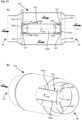
- FIG. 13 A simplified guide section 292 is shown with a deflection element 298 designed as a conical ring.
- the annular deflection element 298 is held by several webs 201 in a central or central area of the flow cross section. Due to the conical design of the annular deflection element 298, incoming air is displaced radially outwards. A free space or a recess 301 is provided inside the deflection element 298, through which air can flow in the axial direction essentially undisturbed.
- Guide section 192 shown can be used in a heating module 12.
- further radially outer structural configurations are omitted or not shown, even if corresponding adjustments or structural configurations may be required for installation in a heating module 12.
- the Figure 14 shows in the partial figures A) and B) two perspective and simplified representations of a displacement element 324, which is designed as a plate.
- the displacement element 324 is here, for example, attached to the second guide section 394 via radial struts 325.
- the exemplary embodiment shown is a flat and curvature-free plate. In alternative embodiments, these are concave or convex or possibly otherwise curved plates, for example in shape similar to that in Figure 6 or 7 Displacer element 124 shown.
- the displacer element 324 is designed here as a circular plate. However, it is also conceivable that the displacement element 324 be a polygonal plate, for example a hexagon, an octagon or the like.
- a sensor element 330 is shown schematically in the flow direction SR behind the displacement element 324.
- the position of the sensor element 330 is in particular such that it is in the recirculation area (indicated by curved arrows RG) of the displacer element 324.
- This design is intended in addition to the designs with the webs.
- the embodiment shown can be used, for example, on the air inlet opening 56 (see Fig. 3 to 5 ) or at the air outlet opening 58 (please refer Fig. 3 to 5 ) of the heating module can be arranged so that the temperature of the air supplied or removed can be measured.
- the Figure 15 shows in the partial figures A) and B) a simplified longitudinal sectional view and a simplified perspective partial sectional view of a displacement element 424 in the central region of the heating module or the air guide element 476 and thus in the region in which the supplied air is heated.
- the central cylindrical - here primarily tubular - section 424a is delimited by two covers 424b, 424c, which are each designed here as flat plates. However, the plates could also be curved.
- a sensor element 430 is also arranged in the cylindrical section 424a, which here, as in the other embodiments, is also located on the longitudinal axis LA.
- the middle section 424a is received at its axial ends in recesses 429b, 429c in the covers 424b, 424c.
- the recesses 429b, 429b can be designed, for example, as an annular groove.
- the covers 424b, 424c and the middle section 424a held by them are arranged in the air guide element 476 by means of struts 425.
- the air flows around the displacement element 424, in particular around the central sections 424a from the air inlet opening 56 ( Fig. 3 to 5 ) to the air outlet opening 58 ( Fig. 3 to 5 ) of the heating module.
- the air in the recess or in the interior 424d of the displacement element 424 or the central section 424a flows in the opposite direction UR, i.e. back towards the air inlet opening 56. Therefore, there are open feed areas 427 and discharge areas at both ends of the cylindrical section 424a 427 for the air.
- the air flow counter to the main flow direction SR is in the Figure 15A illustrated by corresponding arrows UR.
- the air guide element 476 of the Figure 15 has a substantially symmetrical structure with respect to a central plane which orthogonally intersects the longitudinal axis LA. Accordingly, a heating module with such a design of the air guide element 476 can be installed in any orientation in the flow path of a heating system.
- FIG 16A shows the heating module 12 in a simplified perspective view, as already shown in the Figures 2 to 9 has been presented.
- a bent or curved pipe piece 41 is attached to the air inlet opening 56.
- the pipe or the pipe bend 41 is already in the Fig. 5
- Pipe adapter 44 shown is connected to the module housing 36.
- a curved or bent hose (not shown) to the air inlet opening 56, in particular using the pipe adapter 44 or an adapter that may be adapted for hose connections.
- the pipe bend 41 is an exemplary embodiment of an air duct component that serves to homogenize the flow of air that is supplied to the first heating module 12.
- the curved or curved pipe section 41 serves in particular to supply air conveyed by a blower (not shown) to the heating module 12 in a flow that is as homogeneous as possible. If an air flow that is as homogeneous as possible is supplied, the effectiveness of the heating module 12 is increased.
- Figure 16B shows a sectional view (longitudinal section) through the pipe section 41 and the transition into the module housing 36.
- Several ribs or curved sections 43 are formed in the pipe bend 41. These ribs or arch sections 43 serve to guide air and are examples of deflection elements inside the air guide component.
- Four ribs or arch sections 43 are shown as an example, resulting in five paths 45 in which air can flow. Through the ribs or arch sections 43, air in the tracks 45 can be guided specifically in the direction of the deflection elements 98. In other words, it can also be said that the deflection elements 98 are lengthened by the ribs or arch sections 43.
- the pipe adapter 44 has an upstream first section 44b with a first inner diameter IM1.
- a second section 44c with a second inner diameter IM2 follows downstream.
- the first inside diameter IM1 is larger than the second inside diameter.
- the transition between the first section 44b and the second section 44c is formed by a stop surface 47.
- a (straight) pipe or a hose or the curved pipe section 41 can rest on this stop surface 47.
- the outer diameter of the pipe section 41 is matched to the inner diameter IM1 of the first section 44b.
- Figure 16C shows the pipe adapter in a simplified perspective view.
- the two sections 44b and 44c can be seen.
- the stop surface 47 is along the inner circumference of the two sections 44b, 44c visible.
- Locking elements 49 can be provided on the first section 44b, in which a pipe or hose to be connected is accommodated.
- the illustration shows two latching elements 49 as an example, the number of latching elements 49 not being limited to two, but can also be larger. It goes without saying that corresponding counterparts are also present on the pipe or hose, in particular locking recesses into which the locking elements 49 can engage.
- guide recesses 51 can also be arranged on the first section 44b. Corresponding guide elements that are present on the pipe to be connected (eg pipe bend 41) or on the hose to be connected can be inserted into such guide recesses 51.
- the pipe adapter 44 can be connected to the module housing 12, for example, by several screw connections 53.
- interlocking or corresponding connecting structures on the pipe adapter 44 and on the pipe or pipe bend 41 to be connected can also be designed differently than the locking elements 49 and guide recesses 51 shown here.
- the locking elements and corresponding snap-in receptacles could be arranged interchangeably, the same applies for guide recesses and corresponding guide elements.
- the pipe bend 41 is free of curvature and is therefore equal to a straight piece of pipe.
- the ribs or arch sections 43 of this embodiment of the pipe bend 41 are therefore also free of curvature in this embodiment.
- the ones here with reference to the Figures 1 to 4 presented heating system 10 or that here with reference to the Figures 5 to 16 presented (first) heating module 12 enable a heating system to be set up or an existing heating arrangement to be expanded in a habitable vehicle in a flexible manner.
- the (first) heating module 12 is designed as a compact electric heater, which can be easily connected to air-conducting elements in such a way that air can be heated by means of the (first) heating module 12.
- the (first) heating module 12 does not have its own (integrated) fan, but rather is connected to a separate fan, which can in particular also be part of an existing heater (second heating module 28).
Landscapes
- Engineering & Computer Science (AREA)
- Physics & Mathematics (AREA)
- Thermal Sciences (AREA)
- Mechanical Engineering (AREA)
- Chemical & Material Sciences (AREA)
- Combustion & Propulsion (AREA)
- General Engineering & Computer Science (AREA)
- Air-Conditioning For Vehicles (AREA)
- Direct Air Heating By Heater Or Combustion Gas (AREA)
Claims (4)
- Module de chauffage (12) pour une installation de chauffage (10) d'un véhicule habitable comprenant- un boîtier de module (36) comprenant une ouverture d'entrée d'air (56) et une ouverture de sortie d'air (58),- un élément de guidage d'air (76) logé dans le carter de module (36), qui présente plusieurs sections de guidage (92, 94, 96) et qui est relié à l'ouverture d'entrée d'air (56) et l'ouverture de sortie d'air (58), et comprenant- au moins un élément chauffant (110, 112 ; 210, 212), dans lequel l'élément chauffant (110, 112 ; 210, 212) est installé pour réchauffer l'air qui s'écoule de l'ouverture d'entrée d'air (56) à l'ouverture de sortie d'air (58) ;dans lequel l'élément de guidage d'air (76) présente les sections de guidage suivantes :- une première section de guidage (92) qui est reliée à l'ouverture d'entrée d'air (56),- une deuxième section de guidage (94) qui est reliée à l'ouverture de sortie d'air (58), et- une troisième section de guidage (96) qui est logée entre les première et deuxième sections de guidage (92, 94) et est reliée à celles-ci ;et dans lequel- l'élément chauffant (110, 112 ; 210, 212) est logé dans la troisième section de guidage (96);caractérisé en ce que- le module de chauffage (12) présente un dispositif à capteur (130) qui est installé pour capter la température de l'air traversant le module de chauffage (12) ;- le dispositif à capteur (130) est disposé dans un logement de capteur (128) qui est tenu par plusieurs passerelles (102), et dans lequel les passerelles (102) s'étendent dans la direction radiale (RR) à partir du logement de capteur (128) ; et que- quelques passerelles (102) ou toutes comportent un canal de guidage d'air (132) qui est formé de manière à conduire l'air traversant dans la direction du dispositif à capteur (130).
- Module de chauffage selon la revendication 1, dans lequel quelques passerelles (102) ou toutes sont constituées d'un matériau thermiquement conducteur, d'une conductivité thermique supérieure ou égale à 15 W/(m*K).
- Module de chauffage selon l'une des revendications précédentes, dans lequel le dispositif à capteur (130) est conformé en fusible (118) qui réagit au dépassement d'une température.
- Module de chauffage selon l'une des revendications précédentes, dans lequel- plusieurs protections thermiques (118) sont disposées dans la troisième section de guidage (96),- l'élément chauffant (110, 112; 210, 212) présente plusieurs composants chauffants (110, 112 ; 210, 212), et dans lequel- à chaque composant chauffant (110, 112 ; 210, 212) est associé une protection thermique (118).
Applications Claiming Priority (2)
| Application Number | Priority Date | Filing Date | Title |
|---|---|---|---|
| DE102017129031.1A DE102017129031A1 (de) | 2017-12-06 | 2017-12-06 | Heizmodul für eine Heizanlage eines bewohnbaren Fahrzeugs |
| PCT/EP2018/083348 WO2019110506A2 (fr) | 2017-12-06 | 2018-12-03 | Module de chauffage pour système de chauffage d'un véhicule habitable |
Publications (2)
| Publication Number | Publication Date |
|---|---|
| EP3720726A2 EP3720726A2 (fr) | 2020-10-14 |
| EP3720726B1 true EP3720726B1 (fr) | 2024-01-24 |
Family
ID=64650379
Family Applications (1)
| Application Number | Title | Priority Date | Filing Date |
|---|---|---|---|
| EP18815148.4A Active EP3720726B1 (fr) | 2017-12-06 | 2018-12-03 | Module de chauffage pour système de chauffage d'un véhicule habitable |
Country Status (7)
| Country | Link |
|---|---|
| US (1) | US11541724B2 (fr) |
| EP (1) | EP3720726B1 (fr) |
| CN (1) | CN111372797B (fr) |
| AU (1) | AU2018379143B2 (fr) |
| CA (1) | CA3081444C (fr) |
| DE (1) | DE102017129031A1 (fr) |
| WO (1) | WO2019110506A2 (fr) |
Families Citing this family (3)
| Publication number | Priority date | Publication date | Assignee | Title |
|---|---|---|---|---|
| CN115518853B (zh) * | 2022-09-14 | 2023-12-05 | 浙江日鼎涂装科技有限公司 | 一种加热室空气热交换结构 |
| WO2024134349A1 (fr) * | 2022-12-19 | 2024-06-27 | Gentherm Gmbh | Module de chauffage par convection |
| USD1017782S1 (en) * | 2023-06-19 | 2024-03-12 | Wenyong Wang | Recirculation parking heater |
Citations (2)
| Publication number | Priority date | Publication date | Assignee | Title |
|---|---|---|---|---|
| DE1079808B (de) * | 1957-06-05 | 1960-04-14 | Schilde Maschb Ag | Decken- oder Wandlufterhitzer runder Bauart |
| DE102014215682B3 (de) * | 2014-08-07 | 2015-12-31 | Siemens Aktiengesellschaft | Elektrische Heizvorrichtung |
Family Cites Families (32)
| Publication number | Priority date | Publication date | Assignee | Title |
|---|---|---|---|---|
| US1232598A (en) * | 1913-11-05 | 1917-07-10 | John K Norstrom | Heating and ventilating apparatus. |
| US2656782A (en) * | 1950-01-03 | 1953-10-27 | Trane Co | Adjustable air distributor |
| DE1906045U (de) * | 1964-10-12 | 1964-12-10 | Appbau Rothemuehle Brandt & Kr | Leitschaufelgitter fuer rohrkruemmer in regenerativen lufterhitzern. |
| DE1579775A1 (de) | 1966-06-20 | 1971-04-29 | Oelheizgeraetewerk Veb | Benzin- und OElheizgeraet mit Druckluftzerstaeubung fuer Fahrgastraumheizung |
| DE6930121U (de) * | 1969-07-28 | 1970-03-05 | Lebrecht Knipping | Einrichtung zum elektrischen antrieb eines haartrocken- u. -frisiergeraetes. |
| NL181292C (nl) | 1976-06-08 | 1987-07-16 | Nederlandse Gasunie Nv | Inrichting voor het verbeteren van het stromingsprofiel in een gasleiding. |
| DE8229509U1 (de) | 1982-10-21 | 1983-08-04 | Gebrüder Trox, GmbH, 4133 Neukirchen-Vluyn | Regelventil zum Konstanthalten des Volumenstromes, insbesondere in lufttechnischen Anlagen |
| DE8502450U1 (de) * | 1985-01-30 | 1985-05-15 | Schober, Elisabeth, 8000 München | Stutzen für den Anschluß im Zuluftkanal einer Kraftfahrzeug-Luftheizungsanlage |
| US4610703A (en) * | 1986-01-31 | 1986-09-09 | Thaddeus Kowalczyk | Air purifier for protecting motor vechicle occupants from pollution |
| US4814579A (en) * | 1986-04-07 | 1989-03-21 | Innovative Scientific Development, Inc. | Electric resistance air reating system for an aircraft cabin |
| JPH06281483A (ja) * | 1993-03-25 | 1994-10-07 | Mitsubishi Electric Corp | 空気流量計 |
| DE19753373A1 (de) * | 1996-12-10 | 1998-06-25 | Papst Motoren Gmbh & Co Kg | Axiallüfter-Gehäuse |
| GB2322103A (en) | 1997-02-14 | 1998-08-19 | Philip Alexander Paul Buckley | Rapid de-mister for vehicle windscreens |
| DE19942502A1 (de) * | 1999-09-07 | 2001-03-08 | Bosch Gmbh Robert | Vorrichtung zur Messung von zumindest einem Parameter eines in einer Leitung strömenden Mediums |
| DE10016642A1 (de) * | 2000-04-04 | 2001-10-18 | Bosch Gmbh Robert | Vorrichtung zur Bestimmung zumindest eines Parameters eines strömenden Mediums |
| DE10121904A1 (de) | 2001-05-03 | 2002-11-14 | Buhler Motor Gmbh | Belüftungsvorrichtung für Fahrzeuge |
| AU2002365285A1 (en) * | 2001-11-19 | 2003-06-10 | Care Key Gmbh | Device and method for heating at least one window pane in a motor vehicle |
| DE20304546U1 (de) * | 2003-03-24 | 2003-05-22 | Thomae, Uwe, 98646 Gleichamberg | Elektrische Kfz-Heizung |
| US20060249499A1 (en) | 2005-05-06 | 2006-11-09 | Winkler Wolfgang A | Heating unit |
| JP5012249B2 (ja) | 2006-08-07 | 2012-08-29 | 株式会社デンソー | 車両空調用吹出ダクトおよび車両用空調装置 |
| DE102006048440A1 (de) | 2006-10-12 | 2008-04-17 | Webasto Ag | System mit einem modular ausgebildeten Heizgerät und Verfahren zum Wechseln eines Moduls des Heizgeräts |
| DE102007006058B4 (de) | 2007-02-02 | 2009-11-26 | Microhellix Systems Gmbh | Elektrisches Heizmodul zur Luftstromerwärmung, insbesondere zur Heizung und Belüftung von Sitzen |
| US20090239463A1 (en) | 2008-03-20 | 2009-09-24 | Lakhi Goenka | Diffuser for a heating, ventilating, and air conditioning system |
| ES2569509T3 (es) * | 2009-11-09 | 2016-05-11 | Dbk David + Baader Gmbh | Radiador eléctrico |
| DE102010001811B4 (de) * | 2010-02-11 | 2019-05-16 | Mahle International Gmbh | Luftausströmer und Kraftfahrzeugklimaanlage |
| KR101406369B1 (ko) | 2010-06-11 | 2014-06-12 | 현대자동차주식회사 | 저소음 연소식 히터장치 |
| DE102010031127A1 (de) * | 2010-07-08 | 2012-01-12 | Endress + Hauser Flowtec Ag | Messaufnehmer eines thermischen Durchflussmessgeräts zur Ermittlung des Durchflusses eines Mediums durch ein Messrohr und Verfahren zu dessen Herstellung |
| DE102013001441B4 (de) | 2013-01-29 | 2015-07-16 | Esw Gmbh | Heizungsanordnung zum Aufheizen eines die Heizungsanordnung durchströmenden Mediums |
| GB2539131B (en) | 2014-03-27 | 2018-11-28 | Trane Int Inc | Diffuser collar for a condenser fan in an HVAC system |
| AU2015391344B2 (en) * | 2015-04-14 | 2018-11-29 | EJOT AUSTRIA GmbH & Co. KG | Support for fastening façade elements |
| DE102015016613A1 (de) * | 2015-12-22 | 2017-06-22 | Liebherr-Transportation Systems Gmbh & Co. Kg | Lüfter mit Heizfunktion |
| KR101715575B1 (ko) * | 2016-10-12 | 2017-03-13 | 주식회사 희성 | 캠핑트레일러 또는 캠핑카의 원격 제어시스템 및 제어방법 |
-
2017
- 2017-12-06 DE DE102017129031.1A patent/DE102017129031A1/de active Pending
-
2018
- 2018-12-03 WO PCT/EP2018/083348 patent/WO2019110506A2/fr unknown
- 2018-12-03 AU AU2018379143A patent/AU2018379143B2/en active Active
- 2018-12-03 US US16/770,353 patent/US11541724B2/en active Active
- 2018-12-03 EP EP18815148.4A patent/EP3720726B1/fr active Active
- 2018-12-03 CA CA3081444A patent/CA3081444C/fr active Active
- 2018-12-03 CN CN201880068324.5A patent/CN111372797B/zh active Active
Patent Citations (2)
| Publication number | Priority date | Publication date | Assignee | Title |
|---|---|---|---|---|
| DE1079808B (de) * | 1957-06-05 | 1960-04-14 | Schilde Maschb Ag | Decken- oder Wandlufterhitzer runder Bauart |
| DE102014215682B3 (de) * | 2014-08-07 | 2015-12-31 | Siemens Aktiengesellschaft | Elektrische Heizvorrichtung |
Also Published As
| Publication number | Publication date |
|---|---|
| AU2018379143B2 (en) | 2022-06-23 |
| US20200298667A1 (en) | 2020-09-24 |
| CN111372797A (zh) | 2020-07-03 |
| DE102017129031A1 (de) | 2019-06-06 |
| EP3720726A2 (fr) | 2020-10-14 |
| WO2019110506A2 (fr) | 2019-06-13 |
| WO2019110506A3 (fr) | 2019-08-15 |
| WO2019110506A4 (fr) | 2019-10-17 |
| CA3081444A1 (fr) | 2019-06-13 |
| US11541724B2 (en) | 2023-01-03 |
| CN111372797B (zh) | 2023-05-23 |
| AU2018379143A1 (en) | 2020-04-16 |
| CA3081444C (fr) | 2022-11-22 |
Similar Documents
| Publication | Publication Date | Title |
|---|---|---|
| EP3720726B1 (fr) | Module de chauffage pour système de chauffage d'un véhicule habitable | |
| DE69809652T2 (de) | Verteiler für Röhrenwärmetauscher einer Zweiphasenkältemittel-Kühlanlage | |
| EP2653770A1 (fr) | Connecteur, en particulier connecteur rapide | |
| EP3084163B1 (fr) | Agencement de tube mélangeur comportant un boîtier | |
| DE19920061C1 (de) | Heizungs- oder Klimaanlage für eine Fahrgastzelle eines Kraftfahrzeugs | |
| DE10261966B4 (de) | Luftheizgerät zur Integration in eine luftführende Gehäuseanordnung | |
| DE10211591B4 (de) | Luftheizgerät zur Integration in eine luftführende Gehäuseanordnung | |
| DE102015114648A1 (de) | Garofen mit vorrichtung zur verteilung von wasser für die erzeugung von dampf im inneren der garkammer des ofens | |
| DE3303987C2 (fr) | ||
| WO2019110508A2 (fr) | Système de chauffage modulaire pour un véhicule habitable | |
| EP2821729B1 (fr) | Échangeur thermique et dispositif de chauffage | |
| DE2847017C2 (de) | Zuluftauslaß für die Decke von zu belüftenden und zu klimatisierenden Räumen | |
| EP3507559A1 (fr) | Intégration d'échangeur de chaleur | |
| WO2020030506A1 (fr) | Appareil de chauffage électrique | |
| DE102007020531A1 (de) | Heißlufteinrichtung mit einem im Luftstrom angeordneten Heizelement | |
| EP3447378A1 (fr) | Appareil chauffant pour véhicule | |
| EP3234471B1 (fr) | Profilé de radiateur de plafond | |
| WO2018127373A1 (fr) | Dispositif d'échange d'air entre deux espaces pouvant tourner l'un par rapport à l'autre | |
| DE102011088568B4 (de) | Fahrzeugheizgerät | |
| EP1571021B1 (fr) | Module d'aspiration et de soufflage d'air pour un appareil de chauffage | |
| DE102015109510B4 (de) | Ventilanordnung, insbesondere für ein Fahrzeugtemperiergerät, und Temperiergerät | |
| EP3385628A1 (fr) | Élément chauffant pour soupape | |
| DE102013009515A1 (de) | Klimaanlage für ein Fahrzeug | |
| DE102018120374A1 (de) | Luftverteiler für ein Warmluft erzeugendes Heizgerät | |
| WO2024056808A1 (fr) | Échangeur de chaleur modulaire et appareil de ventilation |
Legal Events
| Date | Code | Title | Description |
|---|---|---|---|
| STAA | Information on the status of an ep patent application or granted ep patent |
Free format text: STATUS: UNKNOWN |
|
| STAA | Information on the status of an ep patent application or granted ep patent |
Free format text: STATUS: THE INTERNATIONAL PUBLICATION HAS BEEN MADE |
|
| PUAI | Public reference made under article 153(3) epc to a published international application that has entered the european phase |
Free format text: ORIGINAL CODE: 0009012 |
|
| STAA | Information on the status of an ep patent application or granted ep patent |
Free format text: STATUS: REQUEST FOR EXAMINATION WAS MADE |
|
| 17P | Request for examination filed |
Effective date: 20191202 |
|
| AK | Designated contracting states |
Kind code of ref document: A2 Designated state(s): AL AT BE BG CH CY CZ DE DK EE ES FI FR GB GR HR HU IE IS IT LI LT LU LV MC MK MT NL NO PL PT RO RS SE SI SK SM TR |
|
| AX | Request for extension of the european patent |
Extension state: BA ME |
|
| RIN1 | Information on inventor provided before grant (corrected) |
Inventor name: POHLMUELLER, ADAM Inventor name: LAGING, JOHANNES Inventor name: MOEHRING, MARIO Inventor name: UENNUE, KAMIL Inventor name: PIEGSA, SIEGFRIED Inventor name: ERDOGAN, FIKRET Inventor name: DOEMOETOER, MIHAI |
|
| DAV | Request for validation of the european patent (deleted) | ||
| DAX | Request for extension of the european patent (deleted) | ||
| STAA | Information on the status of an ep patent application or granted ep patent |
Free format text: STATUS: EXAMINATION IS IN PROGRESS |
|
| 17Q | First examination report despatched |
Effective date: 20210709 |
|
| GRAP | Despatch of communication of intention to grant a patent |
Free format text: ORIGINAL CODE: EPIDOSNIGR1 |
|
| STAA | Information on the status of an ep patent application or granted ep patent |
Free format text: STATUS: GRANT OF PATENT IS INTENDED |
|
| INTG | Intention to grant announced |
Effective date: 20230801 |
|
| GRAS | Grant fee paid |
Free format text: ORIGINAL CODE: EPIDOSNIGR3 |
|
| P01 | Opt-out of the competence of the unified patent court (upc) registered |
Effective date: 20231020 |
|
| GRAA | (expected) grant |
Free format text: ORIGINAL CODE: 0009210 |
|
| STAA | Information on the status of an ep patent application or granted ep patent |
Free format text: STATUS: THE PATENT HAS BEEN GRANTED |
|
| AK | Designated contracting states |
Kind code of ref document: B1 Designated state(s): AL AT BE BG CH CY CZ DE DK EE ES FI FR GB GR HR HU IE IS IT LI LT LU LV MC MK MT NL NO PL PT RO RS SE SI SK SM TR |
|
| REG | Reference to a national code |
Ref country code: GB Ref legal event code: FG4D Free format text: NOT ENGLISH |
|
| REG | Reference to a national code |
Ref country code: CH Ref legal event code: EP |
|
| REG | Reference to a national code |
Ref country code: DE Ref legal event code: R096 Ref document number: 502018014051 Country of ref document: DE |
|
| REG | Reference to a national code |
Ref country code: IE Ref legal event code: FG4D Free format text: LANGUAGE OF EP DOCUMENT: GERMAN |
|
| REG | Reference to a national code |
Ref country code: LT Ref legal event code: MG9D |
|
| PG25 | Lapsed in a contracting state [announced via postgrant information from national office to epo] |
Ref country code: NL Free format text: LAPSE BECAUSE OF FAILURE TO SUBMIT A TRANSLATION OF THE DESCRIPTION OR TO PAY THE FEE WITHIN THE PRESCRIBED TIME-LIMIT Effective date: 20240124 |
|
| PG25 | Lapsed in a contracting state [announced via postgrant information from national office to epo] |
Ref country code: NL Free format text: LAPSE BECAUSE OF FAILURE TO SUBMIT A TRANSLATION OF THE DESCRIPTION OR TO PAY THE FEE WITHIN THE PRESCRIBED TIME-LIMIT Effective date: 20240124 |
|
| PG25 | Lapsed in a contracting state [announced via postgrant information from national office to epo] |
Ref country code: IS Free format text: LAPSE BECAUSE OF FAILURE TO SUBMIT A TRANSLATION OF THE DESCRIPTION OR TO PAY THE FEE WITHIN THE PRESCRIBED TIME-LIMIT Effective date: 20240524 |
|
| PG25 | Lapsed in a contracting state [announced via postgrant information from national office to epo] |
Ref country code: LT Free format text: LAPSE BECAUSE OF FAILURE TO SUBMIT A TRANSLATION OF THE DESCRIPTION OR TO PAY THE FEE WITHIN THE PRESCRIBED TIME-LIMIT Effective date: 20240124 |
|
| PG25 | Lapsed in a contracting state [announced via postgrant information from national office to epo] |
Ref country code: GR Free format text: LAPSE BECAUSE OF FAILURE TO SUBMIT A TRANSLATION OF THE DESCRIPTION OR TO PAY THE FEE WITHIN THE PRESCRIBED TIME-LIMIT Effective date: 20240425 |
|
| PG25 | Lapsed in a contracting state [announced via postgrant information from national office to epo] |
Ref country code: HR Free format text: LAPSE BECAUSE OF FAILURE TO SUBMIT A TRANSLATION OF THE DESCRIPTION OR TO PAY THE FEE WITHIN THE PRESCRIBED TIME-LIMIT Effective date: 20240124 Ref country code: RS Free format text: LAPSE BECAUSE OF FAILURE TO SUBMIT A TRANSLATION OF THE DESCRIPTION OR TO PAY THE FEE WITHIN THE PRESCRIBED TIME-LIMIT Effective date: 20240424 |
|
| PG25 | Lapsed in a contracting state [announced via postgrant information from national office to epo] |
Ref country code: ES Free format text: LAPSE BECAUSE OF FAILURE TO SUBMIT A TRANSLATION OF THE DESCRIPTION OR TO PAY THE FEE WITHIN THE PRESCRIBED TIME-LIMIT Effective date: 20240124 |
|
| PG25 | Lapsed in a contracting state [announced via postgrant information from national office to epo] |
Ref country code: RS Free format text: LAPSE BECAUSE OF FAILURE TO SUBMIT A TRANSLATION OF THE DESCRIPTION OR TO PAY THE FEE WITHIN THE PRESCRIBED TIME-LIMIT Effective date: 20240424 Ref country code: NO Free format text: LAPSE BECAUSE OF FAILURE TO SUBMIT A TRANSLATION OF THE DESCRIPTION OR TO PAY THE FEE WITHIN THE PRESCRIBED TIME-LIMIT Effective date: 20240424 Ref country code: LT Free format text: LAPSE BECAUSE OF FAILURE TO SUBMIT A TRANSLATION OF THE DESCRIPTION OR TO PAY THE FEE WITHIN THE PRESCRIBED TIME-LIMIT Effective date: 20240124 Ref country code: IS Free format text: LAPSE BECAUSE OF FAILURE TO SUBMIT A TRANSLATION OF THE DESCRIPTION OR TO PAY THE FEE WITHIN THE PRESCRIBED TIME-LIMIT Effective date: 20240524 Ref country code: HR Free format text: LAPSE BECAUSE OF FAILURE TO SUBMIT A TRANSLATION OF THE DESCRIPTION OR TO PAY THE FEE WITHIN THE PRESCRIBED TIME-LIMIT Effective date: 20240124 Ref country code: GR Free format text: LAPSE BECAUSE OF FAILURE TO SUBMIT A TRANSLATION OF THE DESCRIPTION OR TO PAY THE FEE WITHIN THE PRESCRIBED TIME-LIMIT Effective date: 20240425 Ref country code: FI Free format text: LAPSE BECAUSE OF FAILURE TO SUBMIT A TRANSLATION OF THE DESCRIPTION OR TO PAY THE FEE WITHIN THE PRESCRIBED TIME-LIMIT Effective date: 20240124 Ref country code: ES Free format text: LAPSE BECAUSE OF FAILURE TO SUBMIT A TRANSLATION OF THE DESCRIPTION OR TO PAY THE FEE WITHIN THE PRESCRIBED TIME-LIMIT Effective date: 20240124 Ref country code: BG Free format text: LAPSE BECAUSE OF FAILURE TO SUBMIT A TRANSLATION OF THE DESCRIPTION OR TO PAY THE FEE WITHIN THE PRESCRIBED TIME-LIMIT Effective date: 20240124 |
|
| PG25 | Lapsed in a contracting state [announced via postgrant information from national office to epo] |
Ref country code: PL Free format text: LAPSE BECAUSE OF FAILURE TO SUBMIT A TRANSLATION OF THE DESCRIPTION OR TO PAY THE FEE WITHIN THE PRESCRIBED TIME-LIMIT Effective date: 20240124 Ref country code: PT Free format text: LAPSE BECAUSE OF FAILURE TO SUBMIT A TRANSLATION OF THE DESCRIPTION OR TO PAY THE FEE WITHIN THE PRESCRIBED TIME-LIMIT Effective date: 20240524 |
|
| PG25 | Lapsed in a contracting state [announced via postgrant information from national office to epo] |
Ref country code: SE Free format text: LAPSE BECAUSE OF FAILURE TO SUBMIT A TRANSLATION OF THE DESCRIPTION OR TO PAY THE FEE WITHIN THE PRESCRIBED TIME-LIMIT Effective date: 20240124 Ref country code: PT Free format text: LAPSE BECAUSE OF FAILURE TO SUBMIT A TRANSLATION OF THE DESCRIPTION OR TO PAY THE FEE WITHIN THE PRESCRIBED TIME-LIMIT Effective date: 20240524 Ref country code: PL Free format text: LAPSE BECAUSE OF FAILURE TO SUBMIT A TRANSLATION OF THE DESCRIPTION OR TO PAY THE FEE WITHIN THE PRESCRIBED TIME-LIMIT Effective date: 20240124 Ref country code: LV Free format text: LAPSE BECAUSE OF FAILURE TO SUBMIT A TRANSLATION OF THE DESCRIPTION OR TO PAY THE FEE WITHIN THE PRESCRIBED TIME-LIMIT Effective date: 20240124 |