EP3712701A1 - Système optique de source lumineuse, dispositif de source lumineuse et appareil de projection d'images - Google Patents
Système optique de source lumineuse, dispositif de source lumineuse et appareil de projection d'images Download PDFInfo
- Publication number
- EP3712701A1 EP3712701A1 EP20161850.1A EP20161850A EP3712701A1 EP 3712701 A1 EP3712701 A1 EP 3712701A1 EP 20161850 A EP20161850 A EP 20161850A EP 3712701 A1 EP3712701 A1 EP 3712701A1
- Authority
- EP
- European Patent Office
- Prior art keywords
- optical system
- light source
- light
- optical
- fluorescent
- Prior art date
- Legal status (The legal status is an assumption and is not a legal conclusion. Google has not performed a legal analysis and makes no representation as to the accuracy of the status listed.)
- Granted
Links
- 230000003287 optical effect Effects 0.000 title claims abstract description 322
- 230000005284 excitation Effects 0.000 claims abstract description 120
- 238000006243 chemical reaction Methods 0.000 claims abstract description 64
- 230000014509 gene expression Effects 0.000 claims abstract description 59
- 239000000758 substrate Substances 0.000 claims description 12
- 230000010287 polarization Effects 0.000 description 36
- 230000007423 decrease Effects 0.000 description 18
- 230000001965 increasing effect Effects 0.000 description 12
- 230000003247 decreasing effect Effects 0.000 description 10
- 239000000126 substance Substances 0.000 description 9
- 238000005286 illumination Methods 0.000 description 8
- 239000000463 material Substances 0.000 description 6
- 239000003086 colorant Substances 0.000 description 5
- 230000000052 comparative effect Effects 0.000 description 5
- 239000011521 glass Substances 0.000 description 5
- 229910052751 metal Inorganic materials 0.000 description 5
- 239000002184 metal Substances 0.000 description 5
- 238000003491 array Methods 0.000 description 4
- 239000013078 crystal Substances 0.000 description 4
- 230000009467 reduction Effects 0.000 description 4
- 239000011230 binding agent Substances 0.000 description 3
- 229910019990 cerium-doped yttrium aluminum garnet Inorganic materials 0.000 description 3
- 238000009792 diffusion process Methods 0.000 description 3
- 230000000694 effects Effects 0.000 description 3
- 239000004973 liquid crystal related substance Substances 0.000 description 3
- QSHDDOUJBYECFT-UHFFFAOYSA-N mercury Chemical compound [Hg] QSHDDOUJBYECFT-UHFFFAOYSA-N 0.000 description 3
- 229910052753 mercury Inorganic materials 0.000 description 3
- 229910052761 rare earth metal Inorganic materials 0.000 description 3
- 150000002910 rare earth metals Chemical class 0.000 description 3
- 238000002310 reflectometry Methods 0.000 description 3
- 238000012986 modification Methods 0.000 description 2
- 230000004048 modification Effects 0.000 description 2
- 238000010521 absorption reaction Methods 0.000 description 1
- 230000004075 alteration Effects 0.000 description 1
- 229910052782 aluminium Inorganic materials 0.000 description 1
- XAGFODPZIPBFFR-UHFFFAOYSA-N aluminium Chemical compound [Al] XAGFODPZIPBFFR-UHFFFAOYSA-N 0.000 description 1
- 230000005540 biological transmission Effects 0.000 description 1
- 230000008859 change Effects 0.000 description 1
- 230000001427 coherent effect Effects 0.000 description 1
- 239000000470 constituent Substances 0.000 description 1
- 238000001816 cooling Methods 0.000 description 1
- 230000002708 enhancing effect Effects 0.000 description 1
- 230000001678 irradiating effect Effects 0.000 description 1
- 238000012423 maintenance Methods 0.000 description 1
- 238000002844 melting Methods 0.000 description 1
- 230000008018 melting Effects 0.000 description 1
- 238000000034 method Methods 0.000 description 1
Images


Classifications
-
- G—PHYSICS
- G03—PHOTOGRAPHY; CINEMATOGRAPHY; ANALOGOUS TECHNIQUES USING WAVES OTHER THAN OPTICAL WAVES; ELECTROGRAPHY; HOLOGRAPHY
- G03B—APPARATUS OR ARRANGEMENTS FOR TAKING PHOTOGRAPHS OR FOR PROJECTING OR VIEWING THEM; APPARATUS OR ARRANGEMENTS EMPLOYING ANALOGOUS TECHNIQUES USING WAVES OTHER THAN OPTICAL WAVES; ACCESSORIES THEREFOR
- G03B21/00—Projectors or projection-type viewers; Accessories therefor
- G03B21/14—Details
- G03B21/20—Lamp housings
- G03B21/2006—Lamp housings characterised by the light source
- G03B21/2033—LED or laser light sources
- G03B21/204—LED or laser light sources using secondary light emission, e.g. luminescence or fluorescence
-
- G—PHYSICS
- G03—PHOTOGRAPHY; CINEMATOGRAPHY; ANALOGOUS TECHNIQUES USING WAVES OTHER THAN OPTICAL WAVES; ELECTROGRAPHY; HOLOGRAPHY
- G03B—APPARATUS OR ARRANGEMENTS FOR TAKING PHOTOGRAPHS OR FOR PROJECTING OR VIEWING THEM; APPARATUS OR ARRANGEMENTS EMPLOYING ANALOGOUS TECHNIQUES USING WAVES OTHER THAN OPTICAL WAVES; ACCESSORIES THEREFOR
- G03B21/00—Projectors or projection-type viewers; Accessories therefor
- G03B21/14—Details
- G03B21/20—Lamp housings
- G03B21/208—Homogenising, shaping of the illumination light
-
- H—ELECTRICITY
- H04—ELECTRIC COMMUNICATION TECHNIQUE
- H04N—PICTORIAL COMMUNICATION, e.g. TELEVISION
- H04N9/00—Details of colour television systems
- H04N9/12—Picture reproducers
- H04N9/31—Projection devices for colour picture display, e.g. using electronic spatial light modulators [ESLM]
- H04N9/3102—Projection devices for colour picture display, e.g. using electronic spatial light modulators [ESLM] using two-dimensional electronic spatial light modulators
- H04N9/3111—Projection devices for colour picture display, e.g. using electronic spatial light modulators [ESLM] using two-dimensional electronic spatial light modulators for displaying the colours sequentially, e.g. by using sequentially activated light sources
- H04N9/3114—Projection devices for colour picture display, e.g. using electronic spatial light modulators [ESLM] using two-dimensional electronic spatial light modulators for displaying the colours sequentially, e.g. by using sequentially activated light sources by using a sequential colour filter producing one colour at a time
-
- H—ELECTRICITY
- H04—ELECTRIC COMMUNICATION TECHNIQUE
- H04N—PICTORIAL COMMUNICATION, e.g. TELEVISION
- H04N9/00—Details of colour television systems
- H04N9/12—Picture reproducers
- H04N9/31—Projection devices for colour picture display, e.g. using electronic spatial light modulators [ESLM]
- H04N9/3141—Constructional details thereof
- H04N9/315—Modulator illumination systems
- H04N9/3158—Modulator illumination systems for controlling the spectrum
-
- H—ELECTRICITY
- H04—ELECTRIC COMMUNICATION TECHNIQUE
- H04N—PICTORIAL COMMUNICATION, e.g. TELEVISION
- H04N9/00—Details of colour television systems
- H04N9/12—Picture reproducers
- H04N9/31—Projection devices for colour picture display, e.g. using electronic spatial light modulators [ESLM]
- H04N9/3141—Constructional details thereof
- H04N9/315—Modulator illumination systems
- H04N9/3167—Modulator illumination systems for polarizing the light beam
-
- G—PHYSICS
- G03—PHOTOGRAPHY; CINEMATOGRAPHY; ANALOGOUS TECHNIQUES USING WAVES OTHER THAN OPTICAL WAVES; ELECTROGRAPHY; HOLOGRAPHY
- G03B—APPARATUS OR ARRANGEMENTS FOR TAKING PHOTOGRAPHS OR FOR PROJECTING OR VIEWING THEM; APPARATUS OR ARRANGEMENTS EMPLOYING ANALOGOUS TECHNIQUES USING WAVES OTHER THAN OPTICAL WAVES; ACCESSORIES THEREFOR
- G03B21/00—Projectors or projection-type viewers; Accessories therefor
- G03B21/14—Details
- G03B21/20—Lamp housings
- G03B21/2073—Polarisers in the lamp house
Definitions
- the present disclosure relates to a light source optical system, a light source device, and an image projection apparatus.
- a projector focuses light emitted by a light source onto a spatial light modulation element, such as a digital micromirror device (DMD) or a liquid crystal display element, and displays, as a color image, light modulated in accordance with an image signal and emitted from the spatial light modulation element onto a screen.
- a spatial light modulation element such as a digital micromirror device (DMD) or a liquid crystal display element
- a projector in many cases uses, for example, a high-brightness extra-high-pressure mercury lamp in related art.
- the life of such a lamp is short and the maintenance is frequently required.
- the number of projectors using, for example, lasers or light emitting diodes (LEDs) instead of extra-high-pressure mercury lamps is growing. This is because a laser and an LED have longer lives and higher color reproducibility due to monochromaticity compared to an extra-high-pressure mercury lamp.
- a projector irradiates an image display element such as a DMD with light of, for example, three colors including red, green, and blue which are primary colors to form an image. All the three colors can be generated by laser sources; however, this is not desirable because a green laser and a red laser have lower emission efficiencies than a blue laser.
- a method of irradiating a fluorescent body with a blue laser beam as excitation light to obtain fluorescence through wavelength conversion at the fluorescent body and generating red light and green light from the fluorescence.
- JP-6090875-B and JP-2017-194523-A disclose light source optical systems each of which uses (as a combination) such a laser source and a fluorescent body.
- JP-6090875-B discloses an illumination optical system including an excitation light source, a fluorescent-body unit, and a diffusion plate located in an optical path between the excitation light source and the fluorescent-body unit and configured to bring the intensity distribution of the excitation light closer to a uniform state.
- JP-2017-194523-A discloses a light source device including a plurality of light sources, a wavelength conversion element, and a plurality of mirror arrays and a lens array located in optical paths between the plurality of light sources and the wavelength conversion element.
- the light conversion efficiency by a fluorescent body varies in accordance with the energy density of excitation light incident on the fluorescent body.
- the incident excitation light has a high energy density
- the temperature rises and the electrons that exist in the fluorescent body and that can be excited decrease.
- the efficiency decreases.
- the energy density may be uniformized and the spot size may be increased, thereby increasing the light utilization efficiency.
- the diffusion plate is provided between the excitation light source and the fluorescent-body unit, the intensity of the excitation light incident on the fluorescent-body unit may decrease, and the light utilization efficiency of the entire projector may decrease.
- the mirror arrays and the lens array may cause an increase in the size, complexity, and cost of the apparatus.
- absorption by the mirror arrays and the lens array may decrease the efficiency of the excitation light incident on the fluorescent-body unit.
- the present disclosure is completed based on the above-described awareness of disadvantages, and an object of the disclosure is to provide a light source optical system, a light source device, and an image projection apparatus that have high light utilization efficiency and that can be downsized.
- a light source optical system is configured to be used with an excitation light source configured to emit first color light, the light source optical system including wavelength conversion unit configured to receive the first color light emitted by the excitation light source and emit second color light with a wavelength different from a wavelength of the first color light; and a first optical system and a second optical system provided in an optical path between the excitation light source and the wavelength conversion unit.
- the first optical system includes at least one optical element having a negative power.
- the second optical system as a whole has a positive power, and wherein Conditional Expression (1) is satisfied as follows: 1.8 ⁇ Fn / F 2 ⁇ 5.0 , where
- a light source optical system, a light source device, and an image projection apparatus that have high light utilization efficiency and that can be downsized can be provided.
- FIG. 1 schematically illustrates a projector (image projection apparatus) 1 according to a first embodiment.
- the projector 1 includes a housing 10, a light source device 20, a light uniformizing element 30, an illumination optical system 40, an image forming element (image display element) 50, and a projection optical system 60.
- the housing 10 houses the light source device 20, the light uniformizing element 30, the illumination optical system 40, the image forming element 50, and the projection optical system 60.
- the light source device 20 emits, for example, light including wavelengths corresponding to colors of RGB. An inner configuration of the light source device 20 is described later in detail.
- the light uniformizing element 30 mixes the light emitted by the light source device 20 to uniformize the light.
- Examples of the light uniformizing element 30 include a light tunnel that is a combination of four mirrors, a rod integrator, and a fly eye lens.
- the illumination optical system 40 illuminates the image forming element 50 substantially uniformly with the light uniformized by the light uniformizing element 30.
- the illumination optical system 40 includes, for example, at least one lens and at least one reflecting surface.
- the image forming element 50 includes, for example, a light valve, such as a digital micromirror device (DMD), a transmissive liquid crystal panel, or a reflective liquid crystal panel.
- the image forming element 50 modulates light provided for illumination by the illumination optical system 40 (light from a light source optical system of the light source device 20) to form an image.
- the projection optical system 60 magnifies and projects the image formed by the image forming element 50 onto a screen (projection surface) 70.
- the projection optical system 60 includes, for example, at least one lens.
- FIG. 2 schematically illustrates the light source device 20 according to the first embodiment.
- the light source device 20 includes a laser source (excitation light source) 21, a collimator lens 22, a first optical system 23, a polarization beam splitter 24, a 1/4 wave plate 25, a second optical system 26, a fluorescent-body wheel (wavelength conversion unit, fluorescent-body unit) 27, a condenser lens 28, and a color wheel 29 arranged in this order in a light propagation direction.
- a laser source excitation light source
- collimator lens a collimator lens 22
- a first optical system 23 a polarization beam splitter 24
- a 1/4 wave plate 25
- a second optical system 26
- a fluorescent-body wheel wavelength conversion unit, fluorescent-body unit
- condenser lens 28 and a color wheel 29 arranged in this order in a light propagation direction.
- components of the light source device 20 other than the laser source 21 define "a light source optical system”.
- the laser source 21 includes a plurality of light sources (emission spots).
- Each light source of the laser source 21 emits, for example, light in a blue band where the center wavelength of emission intensity is 455 nm (blue laser beam) as excitation light B (first color light) that excites a fluorescent body provided in a fluorescent region (wavelength conversion region) 27D (described later) of the fluorescent-body wheel 27.
- the blue laser beam emitted by each light source of the laser source 21 is linear polarized light in a constant polarized state, and is arranged to be S-polarized light with respect to an incidence surface of the polarization beam splitter 24.
- the blue laser beam emitted by each light source of the laser source 21 is coherent light.
- the excitation light B emitted by each light source of the laser source 21 is not limited to light in the blue band and may be light with wavelengths that can excite the fluorescent body in the fluorescent region 27D of the fluorescent-body wheel 27.
- the number of light sources of the laser source 21 is not limited to 24, and may be 1 to 23, or 25 or more.
- the laser source 21 can include a light source unit including a plurality of light sources arrayed on a substrate (other specific examples are described later in detail).
- the collimator lens 22 includes 24 collimator lenses to correspond to the 24 light sources of the laser source 21. Each collimator lens 22 adjusts the excitation light B emitted by the corresponding light source of the laser source 21 to substantially parallel light.
- the number of collimator lenses 22 can be increased or decreased in accordance with an increase or a decrease in the number of light sources of the laser source 21 so as to correspond to the number of light sources of the laser source 21.
- the first optical system 23 as a whole has a positive power and includes a positive lens (an optical element having a positive power) 23A and a negative lens (an optical element having a negative power) 23B in this order from a side of the laser source 21 toward a side of the fluorescent-body wheel 27.
- the first optical system 23 guides the excitation light B incident thereon as the substantially parallel light from the collimator lenses 22 to the polarization beam splitter 24 while converging the excitation light B.
- a specific configuration and an advantageous effect of the first optical system 23 are described later in detail.
- the polarization beam splitter 24 has a coat that reflects S-polarized light (first polarization component) in the wavelength band of the excitation light B guided from the first optical system 23, whereas transmits P-polarized light (second polarization component) in the wavelength band of the excitation light B guided from the first optical system 23 and fluorescence (second color light) from the fluorescent-body wheel 27. While the polarization beam splitter 24 having a flat-plate shape is used in the first embodiment, a prism polarization beam splitter 24 may be used.
- the polarization beam splitter 24 reflects the S-polarized light in the wavelength band of the excitation light B and transmits the P-polarized light in the wavelength band of the excitation light B in the first embodiment
- the polarization beam splitter 24 may reflect the P-polarized light in the wavelength band of the excitation light B and transmit the S-polarized light in the wavelength band of the excitation light B.
- the polarization beam splitter 24 is located in an optical path between the laser source 21 and the second optical system 26 (fluorescent-body wheel 27), and functions as "a reflecting surface” that reflects one of excitation light B (first color light) and fluorescence Y (second color light) and transmits the other one.
- the polarization beam splitter 24 folds back the optical path, thereby downsizing the light source optical system.
- the 1/4 wave plate 25 is arranged in a state in which the optical axis thereof is inclined by 45 degrees with respect to the linear polarized light of the excitation light B reflected by the polarization beam splitter 24.
- the 1/4 wave plate 25 converts the excitation light B reflected by the polarization beam splitter 24 from the linear polarized light into circular polarized light.
- the second optical system 26 as a whole has a positive power and includes a positive lens (an optical element having a positive power) 26A and a positive lens (an optical element having a positive power) 26B in this order from the side of the laser source 21 toward the side of the fluorescent-body wheel 27.
- the second optical system 26 guides the excitation light B converted into the circular polarized light and being incident thereon from the 1/4 wave plate 25 to the fluorescent-body wheel 27 while converging the excitation light B. A specific configuration and an advantageous effect of the second optical system 26 are described later in detail.
- FIGs. 3A and 3B illustrate a specific structure of the fluorescent-body wheel 27.
- the fluorescent-body wheel 27 includes a disk member (substrate) 27A and a driving motor (driving member) 27C that rotationally drives the disk member 27A around a rotation shaft 27B.
- the disk member 27A can use, but is not limited to, for example, a transparent substrate or a metal substrate (aluminum substrate etc.).
- a large portion in the circumferential direction (in the first embodiment, an angular range of larger than 270°) of the fluorescent-body wheel 27 (disk member 27A) is assigned to a fluorescent region 27D, and a small portion in the circumferential direction (in the first embodiment, an angular range of smaller than 90°) is assigned to an excitation-light reflective region 27E.
- the fluorescent region 27D includes a reflection coat 27D1, a fluorescent-body layer 27D2, and an anti-reflection coat (AR coat) 27D3 layered in this order from a lower-layer side toward an upper-layer side.
- a reflection coat 27D1 a fluorescent-body layer 27D2
- an anti-reflection coat (AR coat) 27D3 layered in this order from a lower-layer side toward an upper-layer side.
- the reflection coat 27D1 has a characteristic of reflecting light in a wavelength region of fluorescence (emission) by the fluorescent-body layer 27D2.
- the reflection coat 27D1 may be omitted (the disk member 27A may have the function of the reflection coat 27D1).
- the fluorescent-body layer 27D2 may use, for example, a substance in which a fluorescent-body material is dispersed into an organic or inorganic binder, a substance in which a crystal of a fluorescent-body material is directly formed, or a rare-earth fluorescent body such as a Ce:YAG-based substance.
- the wavelength band of the fluorescence (emission) by the fluorescent-body layer 27D2 may be, for example, the wavelength band of yellow, blue, green, or red. In the first embodiment, an example is described in which fluorescence (emission) has the wavelength band of yellow. While the fluorescent body is used as the wavelength conversion element in this embodiment, a phosphorescent body or a non-linear optical crystal may be used.
- the anti-reflection coat 27D3 has a characteristic of preventing reflection of light at a surface of the fluorescent-body layer 27D2.
- a reflection coat (reflecting surface) 27E1 having a characteristic of reflecting light in the wavelength region of the excitation light B guided from the second optical system 26 is layered on the excitation-light reflective region 27E.
- the reflection coat 27E1 may be omitted (the disk member 27A may have the function of the reflection coat 27E1).
- the disk member 27A is rotationally driven by the driving motor 27C.
- the irradiation position with the excitation light B on the fluorescent-body wheel 27 moves over time. Consequently, a portion of the excitation light B (first color light) incident on the fluorescent-body wheel 27 is converted by the fluorescent region (wavelength conversion region) 27D into fluorescence Y (second color light) with a wavelength different from the wavelength of the excitation light B (first color light) and the fluorescence Y is emitted.
- the other portion of the excitation light B incident on the fluorescent-body wheel 27 is reflected by the excitation-light reflective region 27E without a change from the excitation light B and is emitted.
- the fluorescent-body wheel 27 (disk member 27A) is rotated to prevent the fluorescent-body wheel 27 from being partly and continuously irradiated with the excitation light and burned, and to obtain a cooling effect of the fluorescent-body wheel 27.
- the numbers and ranges of the fluorescent region 27D and the excitation-light reflective region 27E can be freely determined, and various changes can be made in design.
- two fluorescent regions and two excitation-light reflective regions may be alternately arranged in the circumferential direction at intervals of 90°.
- the excitation light B reflected by the excitation-light reflective region 27E of the fluorescent-body wheel 27 becomes inverted circular polarized light, and passes through the second optical system 26 and the 1/4 wave plate 25 again to be converted into P-polarized light.
- the excitation light B converted into the P-polarized light is transmitted through the polarization beam splitter 24 and is incident on the color wheel 29 through the condenser lens 28.
- the excitation light B incident on the fluorescent region 27D of the fluorescent-body wheel 27 is converted into fluorescence Y and is emitted.
- the fluorescence Y is turned into substantially parallel light by the second optical system 26, passes through the 1/4 wave plate 25, is transmitted through the polarization beam splitter 24, and is incident on the color wheel 29 through the condenser lens 28.
- FIG. 4 schematically illustrates the color wheel 29.
- the color wheel 29 includes a blue region B, a yellow region Y, a red region R, and a green region G divided in the circumferential direction.
- the blue region B corresponds to the excitation-light reflective region 27E of the fluorescent-body wheel 27.
- the yellow region Y, the red region R, and the green region G are brought into synchronization with the fluorescent region 27D of the fluorescent-body wheel 27.
- a transmission diffusion plate (not illustrated) is arranged on the blue region B.
- coherence of the laser source 21 can be reduced, and speckles on the screen 70 can be reduced.
- the yellow region Y directly transmits light in the wavelength region of yellow emitted from the fluorescent-body wheel 27.
- the red region R and the green region G use dichroic mirrors to reflect light in a non-required wavelength range from the wavelengths of yellow and hence obtain light of highly pure colors.
- Light of each color generated by the color wheel 29 in a time-division manner is guided from the light uniformizing element 30 through the illumination optical system 40 to the image forming element 50, forms an image corresponding to the color, and magnifies and projects the image onto the screen 70 by the projection optical system 60. Thus, a color image is obtained.
- the light source optical system includes the laser source 21, the fluorescent-body wheel 27, and the first optical system 23 having a positive power and the second optical system 26 having a positive power, which are provided in this order in an optical path between the laser source 21 and the fluorescent-body wheel 27.
- the first optical system 23 transmits the excitation light B of S-polarized light but does not transmit the fluorescence Y.
- the second optical system 26 transmits the excitation light B of S-polarized light, the excitation light B of P-polarized light, and the fluorescence Y.
- the first optical system 23 and the second optical system 26 are divided in terms of that the first optical system 23 does not transmit the fluorescence Y and the second optical system 26 transmits the fluorescence Y. This is a first example of the way of dividing (the way of sectioning) the first optical system 23 and the second optical system 26.
- the first optical system 23 and the second optical system 26 are divided in terms of that the first optical system 23 does not transmit 50% or more of the fluorescence (second color light) from the fluorescent-body wheel 27 and the second optical system 26 transmits 50% or more of the fluorescence (second color light) from the fluorescent-body wheel 27.
- This is a second example of the way of dividing (the way of sectioning) the first optical system 23 and the second optical system 26.
- the first optical system 23 and the second optical system 26 are divided at a position of the maximum air gap. This is a third example of the way of dividing (the way of sectioning) the first optical system 23 and the second optical system 26.
- the polarization beam splitter (reflecting surface) 24 is located in an optical path between the laser source 21 and the fluorescent-body wheel (wavelength conversion unit) 27.
- the first optical system 23 is disposed between the laser source 21 and the polarization beam splitter (reflecting surface) 24, and the second optical system 26 is disposed between the polarization beam splitter (reflecting surface) 24 and the fluorescent-body wheel (wavelength conversion unit) 27.
- FIG. 5 illustrates an example of configurations of and rays passing through the first optical system 23 and the second optical system 26 according to the first embodiment.
- Table 1 and Table 2 present lens data and aspherical surface data of the first optical system 23 and the second optical system 26.
- R denotes a curvature radius (a paraxial curvature radius for an aspherical surface)
- D denotes a surface distance
- Nd denotes a refractive index
- vd denotes an Abbe number
- K denotes a conic constant of an aspherical surface
- Ai denotes an aspherical constant of i-th order.
- a surface number with * mark in the table is an aspherical surface.
- Equation (1) An aspherical shape is expressed by Equation (1) as follows when C is the reciprocal of a paraxial curvature radius (paraxial curvature), H is a height from the optical axis, K is a conic constant, and X is an aspherical amount in the optical-axis direction using an aspherical coefficient of each order. That is, a paraxial curvature radius, a conic constant, and an aspherical coefficient are given to determine an aspherical shape.
- the positive lens 23A has a biconvex shape and the negative lens 23B has a biconcave shape according to the first embodiment.
- the positive lens 26A has a biconvex shape and the positive lens 26B has a planoconvex shape being convex toward the object side.
- the positive lens 26A has aspherical surfaces on both sides.
- an aperture stop for adjusting the light intensity of the excitation light B is provided (Surface No. 1) at a position immediately before the positive lens 23A of the first optical system 23.
- the first optical system 23 has an optical characteristic such that, when rays parallel to an optical axis A of the first optical system 23 are incident on the first optical system 23, rays emitted from the first optical system 23 are incident on the second optical system 26 while approaching the optical axis A (condensing) at an angle with respect to the optical axis A.
- a focal point of light incident on the second optical system 26 is formed on a side of the second optical system 26 (near side) with respect to the incidence surface of the fluorescent-body wheel 27. Consequently, a spot shape is faded and uniformized, thereby obtaining a large-size and uniform image; and the light condensing density at the fluorescent-body wheel 27 is decreased, thereby increasing light conversion efficiency.
- FIG. 6 illustrates an example of configurations of and rays passing through a first optical system 23 and a second optical system 26 according to a second embodiment.
- Table 3 and Table 4 present lens data and aspherical surface data of the first optical system 23 and the second optical system 26.
- the first optical system 23 and the second optical system 26 according to the second embodiment have configurations similar to the configurations of the first optical system 23 and the second optical system 26 according to the first embodiment (the parameters of the lens curvature, lens distance, and so forth, are different).
- FIG. 7 illustrates an example of configurations of and rays passing through a first optical system 23 and a second optical system 26 according to a third embodiment.
- Table 5 and Table 6 present lens data and aspherical surface data of the first optical system 23 and the second optical system 26.
- the first optical system 23 and the second optical system 26 according to the third embodiment have configurations similar to the configurations of the first optical system 23 and the second optical system 26 according to the first embodiment (the parameters of the lens curvature, lens distance, and so forth, are different).
- FIG. 8 illustrates an example of configurations of and rays passing through a first optical system 23 and a second optical system 26 according to a fourth embodiment.
- Table 7 and Table 8 present lens data and aspherical surface data of the first optical system 23 and the second optical system 26.
- the first optical system 23 and the second optical system 26 according to the fourth embodiment have configurations similar to the configurations of the first optical system 23 and the second optical system 26 according to the first embodiment (the parameters of the lens curvature, lens distance, and so forth, are different).
- FIG. 9 illustrates an example of configurations of and rays passing through a first optical system 23 and a second optical system 26 according to a fifth embodiment.
- Table 9 and Table 10 present lens data and aspherical surface data of the first optical system 23 and the second optical system 26.
- the first optical system 23 and the second optical system 26 according to the fifth embodiment have configurations similar to the configurations of the first optical system 23 and the second optical system 26 according to the first embodiment (the parameters of the lens curvature, lens distance, and so forth, are different).
- the first optical system 23 includes at least one optical element (positive lens 23A) having a positive power, and at least one optical element (negative lens 23B) having a negative power.
- the second optical system 26 as a whole has a positive power.
- Conditional Expression (1) is desirably satisfied as follows: 1.8 ⁇ Fn / F 2 ⁇ 5.0 , where
- the conversion efficiency of a wavelength conversion unit is inversely proportional to the light condensing density of excitation light on a wavelength conversion element.
- Power arrangement of the optical element (negative lens 23B) having a negative power of the first optical system 23 and the second optical system 26 serving as a condenser optical system is set in a proper range that satisfies Conditional Expression (1).
- a light beam can be thinned so that an incidence optical path and an emission optical path on and from the fluorescent-body wheel (wavelength conversion unit) 27 do not interfere with each other. Consequently, spots of excitation light on the fluorescent-body wheel (wavelength conversion unit) 27 can be uniformized.
- the light condensing density can be decreased, and the light conversion efficiency can be increased.
- the light source optical system can be downsized.
- the light source optical system can be downsized; however, the light condensing density of the excitation light on the wavelength conversion unit excessively increases. Thus, the light conversion efficiency is decreased, and a burn may occur. If the value is above the upper limit of Conditional Expression (1), spots of the excitation light on the wavelength conversion element can be uniformized. Thus, the light condensing density can be decreased, and the light conversion efficiency can be increased. However, the light source optical system may increase in size.
- Conditional Expression (1') is desirably satisfied as follows: 1.9 ⁇ Fn / F 2 ⁇ 4.5.
- Conditional Expression (2) is desirably satisfied as follows: 1.5 ⁇ Fp / Fn ⁇ 2.4 , where
- Conditional Expression (2) determines a reduction ratio of light beams by the first optical system 23.
- Conditional Expression (2) is satisfied to optimize the light condensing density of a spot on the fluorescent-body wheel (wavelength conversion unit) 27 and hence to optimize the light conversion efficiency.
- Conditional Expressions (1) and (2) are both satisfied to downsize the light source optical system and to increase the light conversion efficiency at high levels.
- the value is below the lower limit of Conditional Expression (2), the light condensing density of a spot on the wavelength conversion unit increases, thereby decreasing the light conversion efficiency. If the value is above the upper limit of Conditional Expression (2), the light condensing density of a spot on the wavelength conversion unit decreases, thereby increasing the light conversion efficiency.
- the light condensing density of a lens included in the second optical system increases, and a disadvantage such as melting of a lens may occur.
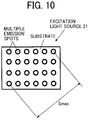
- FIG. 10 illustrates an example of a plurality of emission spots at the laser source 21.
- the laser source 21 includes a plurality of emission spots arranged in a two-dimensional array.
- the plurality of emission spots of the laser source 21 may use, for example, laser diodes (LDs) arranged at a metal block, or a multi-chip component in which laser diode (LD) chips are arranged on a single substrate.
- LDs laser diodes
- Smax the maximum distance between two emission spots from among the plurality of emission spots
- the distance between two spots located in the diagonal direction is the maximum distance, and hence the distance is defined as Smax.
- the outer diameter of an optical element (in this case, the positive lens 26A) of the second optical system 26 disposed on a side of the first optical system 23 is defined as DL.
- the maximum outer diameter of an optical element (in this case, the outer diameter of the positive lens 23A) included in any one of the first optical system 23 and the second optical system 26 is defined as DLmax.
- Conditional Expression (3) is desirably satisfied as follows: Smax / DL ⁇ 2.0 , where
- Conditional Expression (3) determines a size of the plurality of emission spots at the laser source 21.
- Conditional Expression (3) is satisfied to decrease the light condensing density on the fluorescent body and to increase the light conversion efficiency. If the value is above the upper limit of Conditional Expression (3), when the spot diameter on the fluorescent body is to be a desirable size, it is required to increase the reduction ratio of the light source optical system. Consequently, an image of each emission spot on the wavelength conversion unit becomes small and the light condensing density increases, thereby decreasing the light conversion efficiency.
- FIG. 11 illustrates an example of profiles of light when Conditional Expression (3) is satisfied and not satisfied.
- the two cases includes a case where the value of Conditional Expression (3) is larger than 2 (left side), and a case where the value of Conditional Expression (3) is smaller than or equal to 2 (right side).
- the value of Conditional Expression (3) is larger than 2 (left side)
- the reduction ratio is larger than that when the value of Conditional Expression (3) is smaller than or equal to 2.
- Conditional Expression (3') is desirably satisfied as follows: Smax / DL ⁇ 1.7.
- Conditional Expression (4) is desirably satisfied as follows: 0.5 ⁇ Smax / DLmax ⁇ 1.0 , where
- Conditional Expression (4) is satisfied to decrease the size and cost of the light source device, and to increase the light conversion efficiency. If the value is below the lower limit of Conditional Expression (4), the lens outer diameter increases, and the light source device increases in size and cost inevitably. If the value is above the upper limit of Conditional Expression (4), the size and cost of the light source device can be decreased by a certain degree; however, the light conversion efficiency may be decreased.
- the plurality of emission spots of the laser source 21, in particular, two emission spots that satisfy Smax are desirably arranged on a single substrate.
- the laser source 21 including the plurality of emission spots can be easily made.
- the laser source 21 includes the plurality of emission spots arranged in the two-dimensional array.
- the light source device 20 includes the plurality of collimator lenses 22 corresponding to the plurality of respective emission spots of the laser source 21.
- Conditional Expression (5) is desirably satisfied as follows: 0.5 ⁇ Px / L ⁇ tan ⁇ x ⁇ 2.0 , where
- FIG. 12 conceptually illustrates each parameter in Conditional Expression (5) in such a manner that the angle of divergence ⁇ x, the pitch Px, and the distance L are visually recognizable.
- Conditional Expression (5) is satisfied to decrease the distance between profiles of emission spots of the laser source 21.
- Whole profiles are in a dense state, uniform profiles can be obtained when reduced in size on the fluorescent body, and the fluorescent-body conversion efficiency can be increased.
- Conditional Expression (6) is desirably satisfied as follows: 1.6 ⁇ Ndave ⁇ 1.9 , where Ndave is an average value of refractive indices for the d-line of a plurality of optical elements included in the second optical system.
- conditional expression (6) determines an optimal range of refractive indices of optical elements (in this case, the positive lens 26A and the positive lens 26B) included in the second optical system 26.
- Conditional Expression (6) is satisfied to increase the light conversion efficiency of the light source optical system, and to downsize the light source optical system.
- the transmissivity of light with short wavelengths decreases, the transmissivity of excitation light decreases, and the light conversion efficiency of the light source optical system decreases.
- the value is below the lower limit of Conditional Expression (6), the lens thickness or the like increases, and the light source optical system increases in size. Moreover, aberrations increase, and spots are not uniformized. Thus, the light condensing density of excitation light on the wavelength conversion unit increases, and the conversion efficiency of fluorescent decreases.
- Table 11 presents numerical values corresponding to Conditional Expression (1) to Conditional Expression (6) according to the first embodiment to the fifth embodiment. As presented in Table 11, the first embodiment to the fifth embodiment satisfy Conditional Expression (1) to Conditional Expression (6). Table 11 First embodiment Second embodiment Third embodiment Fourth embodiment Fifth embodiment Fn -17.62 -38.54 -19.86 -17.85 -16.62 Fp 35.8 84.8 32.1 31.0 35.8 F2 8.65 8.65 8.65 8.65 8.65 Smax 23 23 23 23 23 23 23 23 DL 25 25 25 25 25 25 25 25 25 25 25 25 25 25 25 25 Px 6 6 6 6 6 L 4.3 4.3 4.3 4.3 6x 45 45 45 45 45 45 45 DLmax 31 31 31 31 31 31 Conditional Expression (1) 2.04 4.45 2.30 2.06 1.92 Conditional Expression (2) 2.03 2.20 1.62 1.73 2.16 Conditional Expression (3) 0.92 0.92 0.92 0.92 0.92 0.92 Conditional Expression (4) 0.74 0.74 0.74 0.74 0.74 Conditional Expression (5) 1.40 1.40 1.40 1.40 1.40 Conditional Expression (6)
- FIGs. 13A to 13G illustrate spot shapes of light according to the first embodiment to the fifth embodiment, and first and second comparative examples.
- the first and second comparative examples do not satisfy a portion or the entirety of lens configurations that are constituent features according to the embodiment or Conditional Expression (1) to Conditional Expression (6).
- FIGs. 13A to 13G illustrate spot shapes of light when excitation light of 1 W is emitted.
- FIG. 13A illustrates spot shapes of light according to the first embodiment, and entirely uniform spot shapes can be obtained.
- the maximum energy density on the fluorescent body is 0.84 W/mm 2 , a burn or the like is prevented from occurring, and fluorescence can be efficiently obtained.
- FIG. 13B illustrates spot shapes of light according to the second embodiment, and entirely uniform spot shapes can be obtained.
- the maximum energy density on the fluorescent body is 0.92 W/mm 2 , a burn or the like is prevented from occurring, and fluorescence can be efficiently obtained.
- FIG. 13C illustrates spot shapes of light according to the third embodiment, and entirely uniform spot shapes can be obtained.
- the maximum energy density on the fluorescent body is 1.21 W/mm 2 , a burn or the like is prevented from occurring, and fluorescence can be efficiently obtained.
- FIG. 13D illustrates spot shapes of light according to the fourth embodiment, and entirely uniform spot shapes can be obtained.
- the maximum energy density on the fluorescent body is 1.36 W/mm 2 , a burn or the like is prevented from occurring, and fluorescence can be efficiently obtained.
- FIG. 13E illustrates spot shapes of light according to the fifth embodiment, and entirely uniform spot shapes can be obtained.
- the maximum energy density on the fluorescent body is 1.49 W/mm 2 , a burn or the like is prevented from occurring, and fluorescence can be efficiently obtained.
- FIG. 13F illustrates spot shapes of light according to a first comparative example, and it is found that spots locally gather at a center portion and the density is high.
- the maximum energy density on the fluorescent body is 2.0 W/mm 2 , and a burn likely occurs.
- FIG. 13G illustrates spot shapes of light according to a second comparative example, and it is found that spots locally gather at a center portion and the density is high.
- the maximum energy density on the fluorescent body is 1.75 W/mm 2 , and a burn likely occurs.
- a projector 1 according to a sixth embodiment is described below in detail with reference to FIGs. 14 and 15 .
- the same reference sign is applied to a configuration common to that of the first embodiment, and the redundant description is omitted.
- the fluorescent-body wheel 27 has a configuration different from that of the first embodiment.
- FIGs. 15A and 15B illustrate a specific structure of a fluorescent-body wheel 27 according to the sixth embodiment.
- the fluorescent-body wheel 27 of the sixth embodiment includes an excitation-light transmissive region 27F instead of the excitation-light reflective region 27E of the first embodiment.
- the excitation-light transmissive region 27F has a characteristic of transmitting light in a wavelength region of the excitation light B guided from the second optical system 26.
- the excitation-light transmissive region 27F has an anti-reflection coat (AR coat, transmitting surface) 27F1 that prevents reflection of the excitation light B guided from the second optical system 26.
- AR coat, transmitting surface anti-reflection coat
- the excitation light B transmitted through the excitation-light transmissive region 27F of the fluorescent-body wheel 27 is turned into parallel light by the collimator lens 80, is converted into circular polarized light by the 1/4 wave plate 81, and is reflected by the reflecting surface 82 to be inverted circular polarized light. Then, the excitation light B is converted into P-polarized light by the 1/4 wave plate 81, is transmitted through the collimator lens 80, the second optical system 26, and the polarization beam splitter 24, and is incident on the color wheel 29 through the condenser lens 28.
- the excitation light B is turned into the parallel light by using the collimator lens 80 in the sixth embodiment, a 1/4 wave plate with no angle dependence may be used and the collimator lens may be omitted. While the collimator lens 80, the 1/4 wave plate 81, and the reflecting surface 82 are optically in contact with one another, the collimator lens 80, the 1/4 wave plate 81, and the reflecting surface 82 may be optically separated from one another.
- the fluorescent-body wheel 27 includes a wavelength conversion region (fluorescent region 27D) that converts excitation light B (first color light) into fluorescence Y (second color light), and a transmissive/reflective region (excitation-light reflective region 27E, excitation-light transmissive region 27F) that transmits or reflects excitation light B (first color light).
- the fluorescent-body wheel 27 can switch light between the excitation light B (first color light) and the fluorescence Y (second color light).
- the configuration of the light source device 20 (light source optical system) can be simplified and downsized.
- a projector 1 according to a seventh embodiment is described below in detail with reference to FIG. 16 .
- the same reference sign is applied to a configuration common to that of the first embodiment, and the redundant description is omitted.
- the seventh embodiment differs from the first embodiment for the following points.
- the excitation light B emitted by the laser source 21 is P-polarized light
- the polarization beam splitter 24 has a characteristic of transmitting the excitation light B of P-polarized light guided from the first optical system 23, and reflecting the excitation light B converted into S-polarized light and fluorescence Y from the 1/4 wave plate 25, the second optical system 26, and the fluorescent-body wheel 27.
- a projector 1 according to an eighth embodiment is described below in detail with reference to FIGs. 17 , 18A, and 18B .
- the same reference sign is applied to a configuration common to that of the first embodiment, and the redundant description is omitted.
- the eighth embodiment differs from the first embodiment in that the condenser lens 28 and the color wheel 29 are omitted and the fluorescent-body wheel 27 has a different configuration.
- FIGs. 18A and 18B illustrate a specific structure of a fluorescent-body wheel 27 according to the eighth embodiment.
- the fluorescent-body wheel 27 of the eighth embodiment is not divided into the fluorescent region 27D and the excitation-light reflective region 27E in the circumferential direction unlike the first embodiment, and a fluorescent region (wavelength conversion region) 27G is provided entirely in the circumferential direction.
- the fluorescent region 27G includes a first reflection coat 27G1, a fluorescent-body layer 27G2, and a second reflection coat 27G3 layered in this order from a lower-layer side toward an upper-layer side.
- the first reflection coat 27G1 has a characteristic of reflecting light in a wavelength region of the excitation light B guided from the second optical system 26 and light in a wavelength region of fluorescence (emission) by the fluorescent-body layer 27G2.
- the fluorescent-body layer 27G2 may use, for example, a substance in which a fluorescent-body material is dispersed into an organic or inorganic binder, a substance in which a crystal of a fluorescent-body material is directly formed, or a rare-earth fluorescent body such as a Ce:YAG-based substance.
- the wavelength band of the fluorescence (emission) by the fluorescent-body layer 27G2 may be, for example, the wavelength band of yellow. Thus, by combining yellow with blue of the excitation light, white light can be obtained.
- the second reflection coat 27G3 has a characteristic of reflecting a portion of the excitation light B guided from the second optical system 26, and transmitting the other portion of the excitation light B guided from the second optical system 26 and the fluorescence (emission) by the fluorescent-body layer 27G2.
- the fluorescent-body layer 27G2 defines "a wavelength conversion region” that converts excitation light (first color light) B into fluorescence (second color light) Y.
- the second reflection coat 27G3 defines "a coat layer” that is provided on a side of the incidence surface of the fluorescent-body layer 27G2 (wavelength conversion region) and reflects a portion of the excitation light (first color light) B.
- a white light source not using time division can be provided.
- the excitation light B reflected by the second reflection coat 27G3 of the fluorescent-body wheel 27 becomes inverted circular polarized light, and passes through the second optical system 26 and the 1/4 wave plate 25 again to be converted into P-polarized light.
- the excitation light B converted into the P-polarized light is transmitted through the polarization beam splitter 24 and is incident on the light uniformizing element 30.
- the excitation light B transmitted through the second reflection coat 27G3 of the fluorescent-body wheel 27 is converted into fluorescence Y by the fluorescent-body layer 27G2 and is reflected by the first reflection coat 27G1.
- the fluorescence Y is turned into substantially parallel light by the second optical system 26, passes through the 1/4 wave plate 25, is transmitted through the polarization beam splitter 24, and is incident on the light uniformizing element 30.
- a projector 1 according to a ninth embodiment is described below in detail with reference to FIGs. 19 , 20A, and 20B .
- the same reference sign is applied to a configuration common to that of the first embodiment, and the redundant description is omitted.
- the ninth embodiment differs from the first embodiment in that the polarization beam splitter 24, the 1/4 wave plate 25, the condenser lens 28, and the color wheel 29 are omitted. Moreover, a dichroic mirror 90 is provided at the position at which the polarization beam splitter 24 is provided in the first embodiment. Furthermore, a blue light source 91, a collimator lens 92, and a third optical system 93 are provided on a side opposite to the first optical system 23 with respect to the dichroic mirror 90.
- the blue light source 91 includes a plurality of light sources (solid-state light sources). Each light source of the blue light source 91 emits light (blue laser beam) in a blue wavelength range that differs from the wavelength range of the excitation light B.
- the collimator lens 92 includes a plurality of collimator lenses to correspond to the plurality of light sources of the blue light source 91.
- FIG. 19 illustrates three blue light sources 91 and three collimator lenses 92 arranged in the upward and downward directions; however, a subset of three blue light sources 91 and a subset of three collimator lenses 92 may be each arranged in a plurality of lines in the direction orthogonal to the figure surface (depth direction) (or may be two dimensionally arranged).
- Each collimator lens 92 adjusts the blue laser beam emitted by the corresponding light source of the blue light source 91 to parallel light.
- the number of blue light sources 91 and the number of collimator lenses 92 can be properly increased or decreased.
- the third optical system 93 includes a biconvex positive lens 93A and a biconcave negative lens 93B.
- the third optical system 93 transmits the blue laser beam emitted by the blue light source 91 and the collimator lens 92 and guides the blue laser beam to the dichroic mirror 90.
- the blue light source 91 may use, for example, a light-emitting diode instead of the laser source.
- the dichroic mirror 90 reflects the excitation light B guided from the first optical system 23 to the second optical system 26, and reflects the blue laser beam guided from the third optical system 93 to the light uniformizing element 30.
- the dichroic mirror 90 transmits the fluorescence from the fluorescent-body wheel 27 to the light uniformizing element 30.
- the excitation light B reflected by the dichroic mirror 90 is incident on the fluorescent-body wheel 27 through the second optical system 26.
- FIGs. 20A and 20B illustrate a specific structure of the fluorescent-body wheel 27 according to the ninth embodiment.
- the fluorescent-body wheel 27 of the ninth embodiment is not divided into the fluorescent region 27D and the excitation-light reflective region 27E in the circumferential direction unlike the first embodiment, and a fluorescent region (wavelength conversion region) 27H is provided entirely in the circumferential direction.
- the fluorescent region 27H includes a reflection coat 27H1, a fluorescent-body layer 27H2, and an anti-reflection coat (AR coat) 27H3 layered in this order from a lower-layer side toward an upper-layer side.
- a reflection coat 27H1 a fluorescent-body layer 27H2
- an anti-reflection coat (AR coat) 27H3 layered in this order from a lower-layer side toward an upper-layer side.
- the reflection coat 27H1 has a characteristic of reflecting light in a wavelength region of the fluorescence (emission) by the fluorescent-body layer 27H2.
- the reflection coat 27H1 may be omitted (the disk member 27A may have the function of the reflection coat 27H1).
- the fluorescent-body layer 27H2 may use, for example, a substance in which a fluorescent-body material is dispersed into an organic or inorganic binder, a substance in which a crystal of a fluorescent-body material is directly formed, or a rare-earth fluorescent body such as a Ce:YAG-based substance.
- the wavelength band of the fluorescence (emission) by the fluorescent-body layer 27H2 may provide white light in combination with, for example, the blue laser beam emitted by each light source of the blue light source 91.
- the anti-reflection coat 27H3 has a characteristic of preventing reflection of light at the fluorescent-body layer 27H2.
- the excitation light B incident on the fluorescent region 27H of the fluorescent-body wheel 27 is converted into fluorescence Y and is emitted.
- the fluorescence Y is turned into substantially parallel light by the second optical system 26, is transmitted through the dichroic mirror 90, and is incident on the light uniformizing element 30.
- the blue laser beam emitted by each light source of the blue light source 91 is turned into parallel light by the collimator lens 92, passes through the third optical system 93, is reflected by the dichroic mirror 90, and is incident on the light uniformizing element 30.
- a projector 1 according to a tenth embodiment is described below in detail with reference to FIGs. 21 and 22 .
- the same reference sign is applied to a configuration common to that of the first embodiment, and the redundant description is omitted.
- the polarization direction may be any direction in the tenth embodiment.
- the light emitted by the laser source 21 is turned into parallel light beams by the collimator lenses 22.
- the parallel light beams pass through the first optical system 23, are reflected by the dichroic mirror 100 that reflects excitation light B and transmits fluorescence Y, and are guided to the second optical system 26.
- the excitation light B is incident on one side of the second optical system 26, and is obliquely incident on the fluorescent-body wheel 27.
- the excitation light B incident on the fluorescent region 27D of the fluorescent-body wheel 27 is converted into fluorescence Y, passes through an optical path similar to that of the first embodiment, and is guided to the light uniformizing element 30.
- the excitation light B incident on the excitation-light reflective region 27E of the fluorescent-body wheel 27 is regularly reflected.
- the excitation light B passes through a side (right side in FIG. 22 ) opposite to a side (left side in FIG. 22 ) of the second optical system 26 on which the excitation light B is incident, and is emitted from the second optical system 26.
- the excitation light B emitted from the second optical system 26 is incident on the condenser lens 28 and is guided to the color wheel 29 and the light uniformizing element 30 without passing through the dichroic mirror 100.
- the dichroic mirror 100 may be alternatively used, the dichroic mirror 100 being increased in size and having a characteristic that a coat on a half surface reflects the excitation light B and transmits the fluorescence Y and a coat on the other half surface transmits the excitation light B and the fluorescence Y.
- a projector 1 according to an eleventh embodiment is described below in detail with reference to FIG. 23 .
- the same reference sign is applied to a configuration common to that of the tenth embodiment, and the redundant description is omitted.
- the eleventh embodiment includes, in addition to a set of the laser source 21 and the collimator lens 22 in the tenth embodiment, a set of a laser source 21X and a collimator lens 22X located below the set of the laser source 21 and the collimator lens 22.
- the set of the laser source 21 and the collimator lens 22 and the set of the laser source 21X and the collimator lens 22X emit excitation light B of P-polarized light.
- the light source device 20 includes a combining optical system 110 that combines the excitation light B emitted by the set of the laser source 21 and the collimator lens 22 and the excitation light B emitted by the set of the laser source 21X and the collimator lens 22X, and that emits the combined light to the first optical system 23.
- the combining optical system 110 includes a 1/2 wave plate 112, a reflecting mirror 114, and a polarization beam splitter 116.
- the 1/2 wave plate 112 converts the excitation light B emitted from the set of the laser source 21X and the collimator lens 22X, from the P-polarized light into S-polarized light.
- the reflecting mirror 114 reflects the excitation light B converted by the 1/2 wave plate 112 into the S-polarized light toward the polarization beam splitter 116.
- the polarization beam splitter 116 has characteristics of reflecting the excitation light B of S-polarized light and transmitting the excitation light B of P-polarized light.
- the polarization beam splitter 116 transmits the excitation light B of P-polarized light emitted by the set of the laser source 21 and the collimator lens 22 and guides the excitation light B of P-polarized light to the first optical system 23.
- the polarization beam splitter 116 reflects the excitation light B of S-polarized light reflected by the reflecting mirror 114 and guides the excitation light B of S-polarized light to the first optical system 23.
- the excitation light B of P-polarized light and the excitation light B of S-polarized light are combined and incident on the first optical system 23.
- the laser source 21 and the laser source 21X are on respective individual substrates.
- Smax1 denotes a distance that is between any two emission spots from among emission spots of the laser source 21 and that is the maximum
- Smax2 denotes a distance that is between any two emission spots from among emission spots of the laser source 21X and that is the maximum
- a large one of Smax1 and Smax2 may serve as Smax.
- both the sets may emit excitation light B of S-polarized light.
- the polarization beam splitter 116 is used to combine the excitation light B in the above-described example, a comb-shaped mirror may be used to combine excitation light B.
Landscapes
- Physics & Mathematics (AREA)
- General Physics & Mathematics (AREA)
- Engineering & Computer Science (AREA)
- Multimedia (AREA)
- Optics & Photonics (AREA)
- Signal Processing (AREA)
- Projection Apparatus (AREA)
- Non-Portable Lighting Devices Or Systems Thereof (AREA)
- Microscoopes, Condenser (AREA)
- Lenses (AREA)
Priority Applications (1)
| Application Number | Priority Date | Filing Date | Title |
|---|---|---|---|
| EP22208800.7A EP4198629A1 (fr) | 2019-03-18 | 2020-03-09 | Système optique de source de lumière, dispositif de source de lumière et appareil de projection d'image |
Applications Claiming Priority (1)
| Application Number | Priority Date | Filing Date | Title |
|---|---|---|---|
| JP2019050033A JP7268421B2 (ja) | 2019-03-18 | 2019-03-18 | 光源光学系、光源装置及び画像投射装置 |
Related Child Applications (2)
| Application Number | Title | Priority Date | Filing Date |
|---|---|---|---|
| EP22208800.7A Division EP4198629A1 (fr) | 2019-03-18 | 2020-03-09 | Système optique de source de lumière, dispositif de source de lumière et appareil de projection d'image |
| EP22208800.7A Division-Into EP4198629A1 (fr) | 2019-03-18 | 2020-03-09 | Système optique de source de lumière, dispositif de source de lumière et appareil de projection d'image |
Publications (2)
| Publication Number | Publication Date |
|---|---|
| EP3712701A1 true EP3712701A1 (fr) | 2020-09-23 |
| EP3712701B1 EP3712701B1 (fr) | 2023-01-04 |
Family
ID=69784199
Family Applications (2)
| Application Number | Title | Priority Date | Filing Date |
|---|---|---|---|
| EP20161850.1A Active EP3712701B1 (fr) | 2019-03-18 | 2020-03-09 | Système optique de source lumineuse, dispositif de source lumineuse et appareil de projection d'images |
| EP22208800.7A Pending EP4198629A1 (fr) | 2019-03-18 | 2020-03-09 | Système optique de source de lumière, dispositif de source de lumière et appareil de projection d'image |
Family Applications After (1)
| Application Number | Title | Priority Date | Filing Date |
|---|---|---|---|
| EP22208800.7A Pending EP4198629A1 (fr) | 2019-03-18 | 2020-03-09 | Système optique de source de lumière, dispositif de source de lumière et appareil de projection d'image |
Country Status (4)
| Country | Link |
|---|---|
| US (2) | US10942434B2 (fr) |
| EP (2) | EP3712701B1 (fr) |
| JP (2) | JP7268421B2 (fr) |
| CN (1) | CN111708247B (fr) |
Cited By (1)
| Publication number | Priority date | Publication date | Assignee | Title |
|---|---|---|---|---|
| CN116430600A (zh) * | 2023-06-13 | 2023-07-14 | 极米科技股份有限公司 | 一种合光系统及投影设备 |
Families Citing this family (10)
| Publication number | Priority date | Publication date | Assignee | Title |
|---|---|---|---|---|
| JP7434808B2 (ja) | 2019-11-01 | 2024-02-21 | 株式会社リコー | 光源装置及び画像投射装置 |
| JP2021092761A (ja) | 2019-12-02 | 2021-06-17 | 株式会社リコー | 光源装置及び画像投射装置 |
| JP6816322B1 (ja) * | 2020-04-28 | 2021-01-20 | デクセリアルズ株式会社 | レーザー装置、投射型画像表示装置及びセンシング装置 |
| JP2021189390A (ja) * | 2020-06-04 | 2021-12-13 | セイコーエプソン株式会社 | 照明装置およびプロジェクター |
| JP2022085665A (ja) | 2020-11-27 | 2022-06-08 | 株式会社リコー | 光源装置、画像投射装置および光源光学系 |
| US11720010B2 (en) | 2020-12-07 | 2023-08-08 | Ricoh Company, Ltd. | Light source device and projection device |
| JP2022114884A (ja) * | 2021-01-27 | 2022-08-08 | 株式会社リコー | 光源装置、および投射装置 |
| JP2022142948A (ja) | 2021-03-17 | 2022-10-03 | 株式会社リコー | 光源装置及び画像投射装置 |
| JP2022167694A (ja) | 2021-04-23 | 2022-11-04 | 株式会社リコー | 導光光学装置、光源装置、および画像投射装置 |
| CN115248527A (zh) * | 2021-04-26 | 2022-10-28 | 成都极米科技股份有限公司 | 光源装置及投影设备 |
Citations (6)
| Publication number | Priority date | Publication date | Assignee | Title |
|---|---|---|---|---|
| US20120140183A1 (en) * | 2010-12-06 | 2012-06-07 | Panasonic Corporation | Light source device and projection display apparatus |
| JP2013114980A (ja) * | 2011-11-30 | 2013-06-10 | Seiko Epson Corp | 光源装置及びプロジェクター |
| US20150167932A1 (en) * | 2012-09-10 | 2015-06-18 | Mitsubishi Electric Corporation | Light source device |
| WO2016148210A1 (fr) * | 2015-03-18 | 2016-09-22 | コニカミノルタ株式会社 | Dispositif de source de lumière et dispositif de projection |
| JP6090875B2 (ja) | 2013-06-04 | 2017-03-08 | Necディスプレイソリューションズ株式会社 | 照明光学系及びプロジェクタ |
| JP2017194523A (ja) | 2016-04-19 | 2017-10-26 | キヤノン株式会社 | 光源装置および画像投射装置 |
Family Cites Families (48)
| Publication number | Priority date | Publication date | Assignee | Title |
|---|---|---|---|---|
| JP5361145B2 (ja) * | 2006-06-08 | 2013-12-04 | キヤノン株式会社 | 照明光学系、画像投射用光学系及び画像投射装置 |
| US7935920B2 (en) | 2006-06-08 | 2011-05-03 | Canon Kabushiki Kaisha | Illumination optical system including luminous flux conversion system |
| JP5703591B2 (ja) | 2010-05-18 | 2015-04-22 | 株式会社リコー | 投射光学系及び画像投射装置 |
| JP2012027113A (ja) | 2010-07-21 | 2012-02-09 | Ricoh Co Ltd | 投射光学系及び画像投射装置 |
| JP5561087B2 (ja) | 2010-10-14 | 2014-07-30 | 株式会社リコー | 画像投射装置 |
| CN103221735B (zh) * | 2010-11-17 | 2015-05-13 | Nec显示器解决方案株式会社 | 光源设备、照明设备和投影型显示设备 |
| JP5907404B2 (ja) | 2011-03-15 | 2016-04-26 | 株式会社リコー | 画像投影装置 |
| JP5783406B2 (ja) * | 2011-03-31 | 2015-09-24 | カシオ計算機株式会社 | 光源装置、及びプロジェクタ |
| US20120293774A1 (en) * | 2011-05-20 | 2012-11-22 | Panasonic Corporation | Projector lens system and image display system using same |
| JP5987368B2 (ja) | 2011-07-05 | 2016-09-07 | 株式会社リコー | 照明装置および投射装置 |
| JP5987382B2 (ja) | 2011-07-22 | 2016-09-07 | 株式会社リコー | 照明装置、ならびに、投射装置および投射装置の制御方法 |
| US20130242533A1 (en) * | 2011-09-12 | 2013-09-19 | Appotronics Corporation Limited | Method and apparatus for a color filter |
| EP2664958B1 (fr) | 2012-05-18 | 2015-10-28 | Ricoh Company, Ltd. | Appareil de source lumineuse et appareil de projection d'image |
| JP6311219B2 (ja) | 2012-07-26 | 2018-04-18 | 株式会社リコー | 照明光形成装置、照明光源装置および画像表示装置 |
| JP6007861B2 (ja) | 2012-08-06 | 2016-10-12 | 株式会社リコー | 光偏向器及び画像投射装置 |
| JP6160274B2 (ja) | 2012-08-16 | 2017-07-12 | 株式会社リコー | 画像投射装置 |
| JP6171345B2 (ja) | 2012-09-10 | 2017-08-02 | 株式会社リコー | 照明光源装置及びこの照明光源装置を備えた投射装置及び投射装置の制御方法 |
| JP6102132B2 (ja) | 2012-09-12 | 2017-03-29 | 株式会社リコー | 照明光源装置及びこの照明光源装置を備えた投射装置及び投射装置の制御方法 |
| JP6056293B2 (ja) | 2012-09-12 | 2017-01-11 | 株式会社リコー | 照明光源装置及びこの照明光源装置を備えた投射装置及び投射装置の制御方法 |
| JP6268745B2 (ja) | 2012-09-18 | 2018-01-31 | 株式会社リコー | 照明装置、投射装置および照明方法 |
| JP5637274B2 (ja) | 2012-12-26 | 2014-12-10 | 株式会社リコー | 光源装置及びこれを用いたプロジェクタ |
| JP2014142369A (ja) * | 2013-01-22 | 2014-08-07 | Zero Rabo Kk | 照明光学系およびこれを用いた電子装置 |
| JP6179792B2 (ja) | 2013-02-26 | 2017-08-16 | 株式会社リコー | 光源装置及びこれを備えた画像投射装置 |
| JP6168387B2 (ja) | 2013-02-26 | 2017-07-26 | 株式会社リコー | 光源装置及びこれを備えた画像投射装置 |
| JP6496977B2 (ja) | 2013-03-13 | 2019-04-10 | 株式会社リコー | 投射光学系、およびプロジェクタ装置 |
| JP6349784B2 (ja) | 2013-03-14 | 2018-07-04 | 株式会社リコー | 光源ユニット並びに照明装置及び画像投射装置 |
| JP6236811B2 (ja) | 2013-03-14 | 2017-11-29 | 株式会社リコー | 光源ユニット並びに照明装置及び画像投射装置 |
| JP2014199412A (ja) | 2013-03-14 | 2014-10-23 | 株式会社リコー | 照明光源装置、およびそれを備える投射装置 |
| JP6205835B2 (ja) | 2013-05-14 | 2017-10-04 | 株式会社リコー | 照明装置、この照明装置を備えた投射装置、および、照明方法 |
| JP6368988B2 (ja) | 2013-05-20 | 2018-08-08 | 株式会社リコー | 投射光学系および画像表示装置 |
| JP6233687B2 (ja) | 2013-08-12 | 2017-11-22 | 株式会社リコー | 光源装置及びこれを備えた画像投射装置 |
| JP2015053227A (ja) | 2013-09-09 | 2015-03-19 | 株式会社リコー | 光源装置および画像表示装置 |
| JP6476667B2 (ja) | 2013-11-01 | 2019-03-06 | 株式会社リコー | 光源装置及びこれを用いたプロジェクタ |
| JP2015094860A (ja) | 2013-11-12 | 2015-05-18 | 株式会社リコー | 照明光源装置および画像投影装置 |
| CA2939461A1 (fr) | 2014-02-17 | 2015-08-20 | Ricoh Company, Ltd. | Dispositif de rayonnement optique et dispositif d'affichage d'image le comprenant |
| EP3121649B1 (fr) | 2014-03-18 | 2019-12-18 | Ricoh Company, Ltd. | Dispositif de source de lumière et dispositif de projection d'image comportant le dispositif de source de lumière |
| US9523842B2 (en) | 2014-06-23 | 2016-12-20 | Ricoh Company, Ltd. | Projection device and projection system |
| JP6547270B2 (ja) | 2014-10-10 | 2019-07-24 | 株式会社リコー | 光源装置及びこの光源装置を有する画像投影装置 |
| US9863759B2 (en) | 2014-10-17 | 2018-01-09 | Ricoh Company, Ltd. | Illumination apparatus, pattern irradiation device, and system |
| JP2017044870A (ja) | 2015-08-26 | 2017-03-02 | 株式会社リコー | 画像表示装置、画像表示ユニット |
| JP6604090B2 (ja) | 2015-08-27 | 2019-11-13 | 株式会社リコー | 投射光学系および投射装置および投射システム |
| JP6206560B2 (ja) | 2015-09-28 | 2017-10-04 | 株式会社リコー | システム |
| JP6641964B2 (ja) * | 2015-12-14 | 2020-02-05 | セイコーエプソン株式会社 | 光源装置及びプロジェクター |
| CN205982969U (zh) * | 2016-08-12 | 2017-02-22 | 深圳市绎立锐光科技开发有限公司 | 光源装置及投影系统 |
| JP6796751B2 (ja) * | 2016-09-26 | 2020-12-09 | パナソニックIpマネジメント株式会社 | 光源装置、及び投写型映像表示装置 |
| JP6371439B1 (ja) * | 2017-04-28 | 2018-08-08 | 株式会社ライトショー・テクノロジー | 光源装置および投射型表示装置 |
| CN108533980B (zh) * | 2018-03-30 | 2020-06-02 | 杨毅 | 激光光源、发光装置和灯具 |
| JP2020030360A (ja) | 2018-08-23 | 2020-02-27 | 株式会社リコー | 光源装置および画像表示装置 |
-
2019
- 2019-03-18 JP JP2019050033A patent/JP7268421B2/ja active Active
-
2020
- 2020-03-09 EP EP20161850.1A patent/EP3712701B1/fr active Active
- 2020-03-09 EP EP22208800.7A patent/EP4198629A1/fr active Pending
- 2020-03-12 CN CN202010169691.3A patent/CN111708247B/zh active Active
- 2020-03-12 US US16/816,264 patent/US10942434B2/en active Active
-
2021
- 2021-02-10 US US17/172,077 patent/US11314157B2/en active Active
-
2023
- 2023-04-19 JP JP2023068166A patent/JP2023099536A/ja active Pending
Patent Citations (6)
| Publication number | Priority date | Publication date | Assignee | Title |
|---|---|---|---|---|
| US20120140183A1 (en) * | 2010-12-06 | 2012-06-07 | Panasonic Corporation | Light source device and projection display apparatus |
| JP2013114980A (ja) * | 2011-11-30 | 2013-06-10 | Seiko Epson Corp | 光源装置及びプロジェクター |
| US20150167932A1 (en) * | 2012-09-10 | 2015-06-18 | Mitsubishi Electric Corporation | Light source device |
| JP6090875B2 (ja) | 2013-06-04 | 2017-03-08 | Necディスプレイソリューションズ株式会社 | 照明光学系及びプロジェクタ |
| WO2016148210A1 (fr) * | 2015-03-18 | 2016-09-22 | コニカミノルタ株式会社 | Dispositif de source de lumière et dispositif de projection |
| JP2017194523A (ja) | 2016-04-19 | 2017-10-26 | キヤノン株式会社 | 光源装置および画像投射装置 |
Cited By (2)
| Publication number | Priority date | Publication date | Assignee | Title |
|---|---|---|---|---|
| CN116430600A (zh) * | 2023-06-13 | 2023-07-14 | 极米科技股份有限公司 | 一种合光系统及投影设备 |
| CN116430600B (zh) * | 2023-06-13 | 2023-09-01 | 极米科技股份有限公司 | 一种合光系统及投影设备 |
Also Published As
| Publication number | Publication date |
|---|---|
| CN111708247B (zh) | 2022-04-08 |
| US11314157B2 (en) | 2022-04-26 |
| JP2023099536A (ja) | 2023-07-13 |
| CN111708247A (zh) | 2020-09-25 |
| US10942434B2 (en) | 2021-03-09 |
| EP4198629A1 (fr) | 2023-06-21 |
| EP3712701B1 (fr) | 2023-01-04 |
| JP7268421B2 (ja) | 2023-05-08 |
| US20200301260A1 (en) | 2020-09-24 |
| US20210173290A1 (en) | 2021-06-10 |
| JP2020154024A (ja) | 2020-09-24 |
Similar Documents
| Publication | Publication Date | Title |
|---|---|---|
| EP3712701B1 (fr) | Système optique de source lumineuse, dispositif de source lumineuse et appareil de projection d'images | |
| US9575401B2 (en) | Light source apparatus and image display apparatus | |
| EP2642178B1 (fr) | Appareil de source de lumière, appareil d'éclairage et appareil d'affichage du type à projection | |
| EP3887904B1 (fr) | Système optique à source lumineuse, dispositif de source lumineuse, et appareil de projection d'image | |
| US7267441B2 (en) | Projection display | |
| EP3816726B1 (fr) | Dispositif de source de lumière et appareil de formation d'image l'incluant | |
| US11669004B2 (en) | Light source optical system, light source device, light source unit, and image display apparatus | |
| US20220382137A1 (en) | Light-source optical system, light-source device, and image display apparatus | |
| JP7428070B2 (ja) | 光源光学系、光源装置及び画像投射装置 | |
| US20220026789A1 (en) | Illumination device and projector | |
| JP2022112217A (ja) | 光源装置および画像投射装置 |
Legal Events
| Date | Code | Title | Description |
|---|---|---|---|
| PUAI | Public reference made under article 153(3) epc to a published international application that has entered the european phase |
Free format text: ORIGINAL CODE: 0009012 |
|
| STAA | Information on the status of an ep patent application or granted ep patent |
Free format text: STATUS: REQUEST FOR EXAMINATION WAS MADE |
|
| 17P | Request for examination filed |
Effective date: 20200309 |
|
| AK | Designated contracting states |
Kind code of ref document: A1 Designated state(s): AL AT BE BG CH CY CZ DE DK EE ES FI FR GB GR HR HU IE IS IT LI LT LU LV MC MK MT NL NO PL PT RO RS SE SI SK SM TR |
|
| AX | Request for extension of the european patent |
Extension state: BA ME |
|
| GRAP | Despatch of communication of intention to grant a patent |
Free format text: ORIGINAL CODE: EPIDOSNIGR1 |
|
| STAA | Information on the status of an ep patent application or granted ep patent |
Free format text: STATUS: GRANT OF PATENT IS INTENDED |
|
| RIC1 | Information provided on ipc code assigned before grant |
Ipc: H04N 9/31 20060101ALN20220720BHEP Ipc: G03B 21/20 20060101AFI20220720BHEP |
|
| INTG | Intention to grant announced |
Effective date: 20220817 |
|
| GRAS | Grant fee paid |
Free format text: ORIGINAL CODE: EPIDOSNIGR3 |
|
| GRAA | (expected) grant |
Free format text: ORIGINAL CODE: 0009210 |
|
| STAA | Information on the status of an ep patent application or granted ep patent |
Free format text: STATUS: THE PATENT HAS BEEN GRANTED |
|
| AK | Designated contracting states |
Kind code of ref document: B1 Designated state(s): AL AT BE BG CH CY CZ DE DK EE ES FI FR GB GR HR HU IE IS IT LI LT LU LV MC MK MT NL NO PL PT RO RS SE SI SK SM TR |
|
| REG | Reference to a national code |
Ref country code: GB Ref legal event code: FG4D |
|
| REG | Reference to a national code |
Ref country code: CH Ref legal event code: EP |
|
| REG | Reference to a national code |
Ref country code: AT Ref legal event code: REF Ref document number: 1542385 Country of ref document: AT Kind code of ref document: T Effective date: 20230115 |
|
| REG | Reference to a national code |
Ref country code: DE Ref legal event code: R096 Ref document number: 602020007277 Country of ref document: DE |
|
| REG | Reference to a national code |
Ref country code: IE Ref legal event code: FG4D |
|
| REG | Reference to a national code |
Ref country code: LT Ref legal event code: MG9D |
|
| PGFP | Annual fee paid to national office [announced via postgrant information from national office to epo] |
Ref country code: FR Payment date: 20230327 Year of fee payment: 4 |
|
| REG | Reference to a national code |
Ref country code: NL Ref legal event code: MP Effective date: 20230104 |
|
| REG | Reference to a national code |
Ref country code: AT Ref legal event code: MK05 Ref document number: 1542385 Country of ref document: AT Kind code of ref document: T Effective date: 20230104 |
|
| P01 | Opt-out of the competence of the unified patent court (upc) registered |
Effective date: 20230522 |
|
| PG25 | Lapsed in a contracting state [announced via postgrant information from national office to epo] |
Ref country code: NL Free format text: LAPSE BECAUSE OF FAILURE TO SUBMIT A TRANSLATION OF THE DESCRIPTION OR TO PAY THE FEE WITHIN THE PRESCRIBED TIME-LIMIT Effective date: 20230104 |
|
| PG25 | Lapsed in a contracting state [announced via postgrant information from national office to epo] |
Ref country code: RS Free format text: LAPSE BECAUSE OF FAILURE TO SUBMIT A TRANSLATION OF THE DESCRIPTION OR TO PAY THE FEE WITHIN THE PRESCRIBED TIME-LIMIT Effective date: 20230104 Ref country code: PT Free format text: LAPSE BECAUSE OF FAILURE TO SUBMIT A TRANSLATION OF THE DESCRIPTION OR TO PAY THE FEE WITHIN THE PRESCRIBED TIME-LIMIT Effective date: 20230504 Ref country code: NO Free format text: LAPSE BECAUSE OF FAILURE TO SUBMIT A TRANSLATION OF THE DESCRIPTION OR TO PAY THE FEE WITHIN THE PRESCRIBED TIME-LIMIT Effective date: 20230404 Ref country code: LV Free format text: LAPSE BECAUSE OF FAILURE TO SUBMIT A TRANSLATION OF THE DESCRIPTION OR TO PAY THE FEE WITHIN THE PRESCRIBED TIME-LIMIT Effective date: 20230104 Ref country code: LT Free format text: LAPSE BECAUSE OF FAILURE TO SUBMIT A TRANSLATION OF THE DESCRIPTION OR TO PAY THE FEE WITHIN THE PRESCRIBED TIME-LIMIT Effective date: 20230104 Ref country code: HR Free format text: LAPSE BECAUSE OF FAILURE TO SUBMIT A TRANSLATION OF THE DESCRIPTION OR TO PAY THE FEE WITHIN THE PRESCRIBED TIME-LIMIT Effective date: 20230104 Ref country code: ES Free format text: LAPSE BECAUSE OF FAILURE TO SUBMIT A TRANSLATION OF THE DESCRIPTION OR TO PAY THE FEE WITHIN THE PRESCRIBED TIME-LIMIT Effective date: 20230104 Ref country code: AT Free format text: LAPSE BECAUSE OF FAILURE TO SUBMIT A TRANSLATION OF THE DESCRIPTION OR TO PAY THE FEE WITHIN THE PRESCRIBED TIME-LIMIT Effective date: 20230104 |
|
| PG25 | Lapsed in a contracting state [announced via postgrant information from national office to epo] |
Ref country code: SE Free format text: LAPSE BECAUSE OF FAILURE TO SUBMIT A TRANSLATION OF THE DESCRIPTION OR TO PAY THE FEE WITHIN THE PRESCRIBED TIME-LIMIT Effective date: 20230104 Ref country code: PL Free format text: LAPSE BECAUSE OF FAILURE TO SUBMIT A TRANSLATION OF THE DESCRIPTION OR TO PAY THE FEE WITHIN THE PRESCRIBED TIME-LIMIT Effective date: 20230104 Ref country code: IS Free format text: LAPSE BECAUSE OF FAILURE TO SUBMIT A TRANSLATION OF THE DESCRIPTION OR TO PAY THE FEE WITHIN THE PRESCRIBED TIME-LIMIT Effective date: 20230504 Ref country code: GR Free format text: LAPSE BECAUSE OF FAILURE TO SUBMIT A TRANSLATION OF THE DESCRIPTION OR TO PAY THE FEE WITHIN THE PRESCRIBED TIME-LIMIT Effective date: 20230405 Ref country code: FI Free format text: LAPSE BECAUSE OF FAILURE TO SUBMIT A TRANSLATION OF THE DESCRIPTION OR TO PAY THE FEE WITHIN THE PRESCRIBED TIME-LIMIT Effective date: 20230104 |
|
| REG | Reference to a national code |
Ref country code: DE Ref legal event code: R097 Ref document number: 602020007277 Country of ref document: DE |
|
| PG25 | Lapsed in a contracting state [announced via postgrant information from national office to epo] |
Ref country code: SM Free format text: LAPSE BECAUSE OF FAILURE TO SUBMIT A TRANSLATION OF THE DESCRIPTION OR TO PAY THE FEE WITHIN THE PRESCRIBED TIME-LIMIT Effective date: 20230104 Ref country code: RO Free format text: LAPSE BECAUSE OF FAILURE TO SUBMIT A TRANSLATION OF THE DESCRIPTION OR TO PAY THE FEE WITHIN THE PRESCRIBED TIME-LIMIT Effective date: 20230104 Ref country code: MC Free format text: LAPSE BECAUSE OF FAILURE TO SUBMIT A TRANSLATION OF THE DESCRIPTION OR TO PAY THE FEE WITHIN THE PRESCRIBED TIME-LIMIT Effective date: 20230104 Ref country code: EE Free format text: LAPSE BECAUSE OF FAILURE TO SUBMIT A TRANSLATION OF THE DESCRIPTION OR TO PAY THE FEE WITHIN THE PRESCRIBED TIME-LIMIT Effective date: 20230104 Ref country code: DK Free format text: LAPSE BECAUSE OF FAILURE TO SUBMIT A TRANSLATION OF THE DESCRIPTION OR TO PAY THE FEE WITHIN THE PRESCRIBED TIME-LIMIT Effective date: 20230104 Ref country code: CZ Free format text: LAPSE BECAUSE OF FAILURE TO SUBMIT A TRANSLATION OF THE DESCRIPTION OR TO PAY THE FEE WITHIN THE PRESCRIBED TIME-LIMIT Effective date: 20230104 |
|
| REG | Reference to a national code |
Ref country code: CH Ref legal event code: PL |
|
| PLBE | No opposition filed within time limit |
Free format text: ORIGINAL CODE: 0009261 |
|
| STAA | Information on the status of an ep patent application or granted ep patent |
Free format text: STATUS: NO OPPOSITION FILED WITHIN TIME LIMIT |
|
| PG25 | Lapsed in a contracting state [announced via postgrant information from national office to epo] |
Ref country code: SK Free format text: LAPSE BECAUSE OF FAILURE TO SUBMIT A TRANSLATION OF THE DESCRIPTION OR TO PAY THE FEE WITHIN THE PRESCRIBED TIME-LIMIT Effective date: 20230104 |
|
| REG | Reference to a national code |
Ref country code: BE Ref legal event code: MM Effective date: 20230331 |
|
| 26N | No opposition filed |
Effective date: 20231005 |
|
| PG25 | Lapsed in a contracting state [announced via postgrant information from national office to epo] |
Ref country code: LU Free format text: LAPSE BECAUSE OF NON-PAYMENT OF DUE FEES Effective date: 20230309 |
|
| REG | Reference to a national code |
Ref country code: IE Ref legal event code: MM4A |
|
| PG25 | Lapsed in a contracting state [announced via postgrant information from national office to epo] |
Ref country code: SI Free format text: LAPSE BECAUSE OF FAILURE TO SUBMIT A TRANSLATION OF THE DESCRIPTION OR TO PAY THE FEE WITHIN THE PRESCRIBED TIME-LIMIT Effective date: 20230104 Ref country code: LI Free format text: LAPSE BECAUSE OF NON-PAYMENT OF DUE FEES Effective date: 20230331 Ref country code: IE Free format text: LAPSE BECAUSE OF NON-PAYMENT OF DUE FEES Effective date: 20230309 Ref country code: CH Free format text: LAPSE BECAUSE OF NON-PAYMENT OF DUE FEES Effective date: 20230331 |
|
| PG25 | Lapsed in a contracting state [announced via postgrant information from national office to epo] |
Ref country code: BE Free format text: LAPSE BECAUSE OF NON-PAYMENT OF DUE FEES Effective date: 20230331 |
|
| PGFP | Annual fee paid to national office [announced via postgrant information from national office to epo] |
Ref country code: DE Payment date: 20240320 Year of fee payment: 5 Ref country code: GB Payment date: 20240321 Year of fee payment: 5 |