WO2016148210A1 - Dispositif de source de lumière et dispositif de projection - Google Patents
Dispositif de source de lumière et dispositif de projection Download PDFInfo
- Publication number
- WO2016148210A1 WO2016148210A1 PCT/JP2016/058401 JP2016058401W WO2016148210A1 WO 2016148210 A1 WO2016148210 A1 WO 2016148210A1 JP 2016058401 W JP2016058401 W JP 2016058401W WO 2016148210 A1 WO2016148210 A1 WO 2016148210A1
- Authority
- WO
- WIPO (PCT)
- Prior art keywords
- light
- light source
- phosphor
- fly
- excitation light
- Prior art date
Links
- 230000005284 excitation Effects 0.000 claims abstract description 107
- OAICVXFJPJFONN-UHFFFAOYSA-N Phosphorus Chemical compound [P] OAICVXFJPJFONN-UHFFFAOYSA-N 0.000 claims abstract description 74
- 230000003287 optical effect Effects 0.000 claims abstract description 60
- 238000009826 distribution Methods 0.000 claims abstract description 22
- 230000010287 polarization Effects 0.000 claims description 61
- 238000006243 chemical reaction Methods 0.000 claims description 12
- 235000005811 Viola adunca Nutrition 0.000 claims description 3
- 240000009038 Viola odorata Species 0.000 claims description 3
- 235000013487 Viola odorata Nutrition 0.000 claims description 3
- 235000002254 Viola papilionacea Nutrition 0.000 claims description 3
- 239000000758 substrate Substances 0.000 claims description 3
- 239000004973 liquid crystal related substance Substances 0.000 description 29
- 238000005286 illumination Methods 0.000 description 16
- 238000000926 separation method Methods 0.000 description 8
- 238000000265 homogenisation Methods 0.000 description 6
- XUIMIQQOPSSXEZ-UHFFFAOYSA-N Silicon Chemical compound [Si] XUIMIQQOPSSXEZ-UHFFFAOYSA-N 0.000 description 2
- 238000010586 diagram Methods 0.000 description 2
- 230000004048 modification Effects 0.000 description 2
- 238000012986 modification Methods 0.000 description 2
- 229910052710 silicon Inorganic materials 0.000 description 2
- 239000010703 silicon Substances 0.000 description 2
- 238000009827 uniform distribution Methods 0.000 description 2
- 238000010521 absorption reaction Methods 0.000 description 1
- 230000005540 biological transmission Effects 0.000 description 1
- 239000002131 composite material Substances 0.000 description 1
- 230000007423 decrease Effects 0.000 description 1
- 230000003247 decreasing effect Effects 0.000 description 1
- 239000000463 material Substances 0.000 description 1
- 239000011159 matrix material Substances 0.000 description 1
- 238000000034 method Methods 0.000 description 1
- 239000000126 substance Substances 0.000 description 1
- 239000002699 waste material Substances 0.000 description 1
Images


Classifications
-
- F—MECHANICAL ENGINEERING; LIGHTING; HEATING; WEAPONS; BLASTING
- F21—LIGHTING
- F21S—NON-PORTABLE LIGHTING DEVICES; SYSTEMS THEREOF; VEHICLE LIGHTING DEVICES SPECIALLY ADAPTED FOR VEHICLE EXTERIORS
- F21S2/00—Systems of lighting devices, not provided for in main groups F21S4/00 - F21S10/00 or F21S19/00, e.g. of modular construction
-
- F—MECHANICAL ENGINEERING; LIGHTING; HEATING; WEAPONS; BLASTING
- F21—LIGHTING
- F21V—FUNCTIONAL FEATURES OR DETAILS OF LIGHTING DEVICES OR SYSTEMS THEREOF; STRUCTURAL COMBINATIONS OF LIGHTING DEVICES WITH OTHER ARTICLES, NOT OTHERWISE PROVIDED FOR
- F21V13/00—Producing particular characteristics or distribution of the light emitted by means of a combination of elements specified in two or more of main groups F21V1/00 - F21V11/00
- F21V13/12—Combinations of only three kinds of elements
- F21V13/14—Combinations of only three kinds of elements the elements being filters or photoluminescent elements, reflectors and refractors
-
- F—MECHANICAL ENGINEERING; LIGHTING; HEATING; WEAPONS; BLASTING
- F21—LIGHTING
- F21V—FUNCTIONAL FEATURES OR DETAILS OF LIGHTING DEVICES OR SYSTEMS THEREOF; STRUCTURAL COMBINATIONS OF LIGHTING DEVICES WITH OTHER ARTICLES, NOT OTHERWISE PROVIDED FOR
- F21V9/00—Elements for modifying spectral properties, polarisation or intensity of the light emitted, e.g. filters
- F21V9/06—Elements for modifying spectral properties, polarisation or intensity of the light emitted, e.g. filters for filtering out ultraviolet radiation
-
- F—MECHANICAL ENGINEERING; LIGHTING; HEATING; WEAPONS; BLASTING
- F21—LIGHTING
- F21V—FUNCTIONAL FEATURES OR DETAILS OF LIGHTING DEVICES OR SYSTEMS THEREOF; STRUCTURAL COMBINATIONS OF LIGHTING DEVICES WITH OTHER ARTICLES, NOT OTHERWISE PROVIDED FOR
- F21V9/00—Elements for modifying spectral properties, polarisation or intensity of the light emitted, e.g. filters
- F21V9/08—Elements for modifying spectral properties, polarisation or intensity of the light emitted, e.g. filters for producing coloured light, e.g. monochromatic; for reducing intensity of light
-
- F—MECHANICAL ENGINEERING; LIGHTING; HEATING; WEAPONS; BLASTING
- F21—LIGHTING
- F21V—FUNCTIONAL FEATURES OR DETAILS OF LIGHTING DEVICES OR SYSTEMS THEREOF; STRUCTURAL COMBINATIONS OF LIGHTING DEVICES WITH OTHER ARTICLES, NOT OTHERWISE PROVIDED FOR
- F21V9/00—Elements for modifying spectral properties, polarisation or intensity of the light emitted, e.g. filters
- F21V9/30—Elements containing photoluminescent material distinct from or spaced from the light source
-
- F—MECHANICAL ENGINEERING; LIGHTING; HEATING; WEAPONS; BLASTING
- F21—LIGHTING
- F21V—FUNCTIONAL FEATURES OR DETAILS OF LIGHTING DEVICES OR SYSTEMS THEREOF; STRUCTURAL COMBINATIONS OF LIGHTING DEVICES WITH OTHER ARTICLES, NOT OTHERWISE PROVIDED FOR
- F21V9/00—Elements for modifying spectral properties, polarisation or intensity of the light emitted, e.g. filters
- F21V9/40—Elements for modifying spectral properties, polarisation or intensity of the light emitted, e.g. filters with provision for controlling spectral properties, e.g. colour, or intensity
- F21V9/45—Elements for modifying spectral properties, polarisation or intensity of the light emitted, e.g. filters with provision for controlling spectral properties, e.g. colour, or intensity by adjustment of photoluminescent elements
-
- G—PHYSICS
- G03—PHOTOGRAPHY; CINEMATOGRAPHY; ANALOGOUS TECHNIQUES USING WAVES OTHER THAN OPTICAL WAVES; ELECTROGRAPHY; HOLOGRAPHY
- G03B—APPARATUS OR ARRANGEMENTS FOR TAKING PHOTOGRAPHS OR FOR PROJECTING OR VIEWING THEM; APPARATUS OR ARRANGEMENTS EMPLOYING ANALOGOUS TECHNIQUES USING WAVES OTHER THAN OPTICAL WAVES; ACCESSORIES THEREFOR
- G03B21/00—Projectors or projection-type viewers; Accessories therefor
- G03B21/14—Details
-
- H—ELECTRICITY
- H04—ELECTRIC COMMUNICATION TECHNIQUE
- H04N—PICTORIAL COMMUNICATION, e.g. TELEVISION
- H04N5/00—Details of television systems
- H04N5/74—Projection arrangements for image reproduction, e.g. using eidophor
Definitions
- the present invention relates to a light source device for illuminating an image display element incorporated in a projection device, and a projection device incorporating such a light source device.
- phosphors have come to be used as light sources for projectors (projectors).
- projectors light emitted from a laser diode or LED is irradiated onto a phosphor, and the fluorescence emitted by wavelength conversion by the phosphor is used (see Patent Documents 1 to 3).
- the fluorescence emitted from the phosphor is applied to an image display element such as a liquid crystal or DMD (digital micromirror device), and an image formed by the image display element is enlarged and projected onto a screen by a projection optical system.
- image display element such as a liquid crystal or DMD (digital micromirror device
- the intensity of the excitation light applied to the phosphor is increased by increasing the output of the excitation light source in order to brighten the projected image on the screen, there is a problem that the light emission efficiency decreases due to the saturation phenomenon of the phosphor. Further, when the excitation light intensity is high, there is a problem that the phosphor is deteriorated and the life is shortened. For these two reasons, it is desirable that the excitation light intensity is not excessively high.
- an area on the surface of the phosphor where the fluorescence can reach the image display element when the phosphor emits light is defined as an effective area.
- This effective area usually has a rectangular shape having substantially the same aspect ratio as that of the image display element.
- the present invention has been made in view of the above-described background art, and a light source device for a projection device that can suppress an increase in the size of an optical system of a light source while uniformly illuminating the entire effective area of a phosphor, and the same
- An object of the present invention is to provide a projection apparatus incorporating the above.
- a light source device for a projection apparatus includes an excitation light source that emits excitation light, a phosphor that emits fluorescence when irradiated with excitation light, an excitation light source, and a phosphor.
- a beam splitter for branching the fluorescence from the optical path of the excitation light, and a fly-eye optical system for equalizing the intensity distribution of the excitation light and the intensity distribution of the fluorescence, the beam splitter and the phosphor At least a part of the fly-eye optical system is disposed in the optical path between the two.
- a projection apparatus includes a light source device for the projection apparatus described above, an image display element illuminated by the light source apparatus for the projection apparatus, and an image display element.
- a projection optical system for projecting an image is a projection optical system for projecting an image.
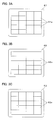
- FIG. 3A is a diagram illustrating a light source device for a projection device according to the second embodiment
- FIG. 4B is a diagram illustrating a phosphor wheel or a phosphor incorporated in the light source device of FIG. 4A. It is a figure explaining the light source device etc. for projectors of a 3rd embodiment.
- the projection device 2 As shown in FIG. 1, the projection device 2 according to the first embodiment enables projection of images corresponding to various video signals, and includes a light source device 21, a polarization beam splitter 22, and a reflective liquid crystal element 23. , A projection optical system 24, and an image drive circuit 25.
- the light source device 21 includes a laser beam forming unit 31 that emits a substantially parallel laser beam L1, a polarization dichroic mirror 32 that branches the optical path of the fluorescence FL from the optical path of the laser beam L1, and a position that changes the polarization state of the laser beam L1.
- Polarized light that aligns the polarization direction of the illumination light L2 emitted from the polarization dichroic mirror 32, the phosphor wheel 35 having the phosphor 41, the composite fly-eye optical system 36 that equalizes the intensity of the excitation light EL and the fluorescence FL
- the conversion part 37 and the field lens 38 which adjusts the incident angle of the illumination light L2 to the reflective liquid crystal element 23 are provided. That is, the polarization dichroic mirror 32 corresponds to a beam splitter that is disposed in the optical path between the excitation light source (laser array 51 described later) and the phosphor 41 and branches the fluorescence FL from the optical path of the excitation light EL.
- the polarization beam splitter (PBS) 22 is a polarization separation type beam splitter.
- the polarization beam splitter 22 is formed by bonding a pair of right-angle prisms. On the bonding surface, the illumination light L2 that is linearly polarized light in a predetermined direction incident from the light source device 21 is selected on the inclined surface of one right-angle prism.
- a polarization separation surface 22a made of a polarization separation film that reflects light is formed. Thereby, the illumination light L ⁇ b> 2 emitted from the light source device 21 can be reflected and incident on a reflective liquid crystal element 23 described later. Further, the image light L 3 reflected by the reflective liquid crystal element 23 can be transmitted and incident on the projection optical system 24.
- the polarization separation surface 22a reflects S-polarized light based on this and transmits P-polarized light.
- the reflective liquid crystal element 23 is a display panel that forms the image light L3, that is, an image display element.
- the reflective liquid crystal element 23 is a light valve or spatial light in that the image light L3 is formed from the illumination light L2 by changing the spatial reflectance. It can be said that it is a modulation element.
- the reflective liquid crystal element (image display element) 23 includes an image display panel that is a plate-like electronic component.
- the reflection type liquid crystal element 23 is a micro display also called LCOS (Liquid crystal on silicon), in which a circuit is directly formed on the surface of a silicon chip and a liquid crystal layer is sandwiched between a counter substrate.
- the reflective liquid crystal element 23 modulates the illumination light L2 by changing the arrangement of liquid crystal molecules, and displays a desired image by reflection. Is.
- S-polarized light with the polarization separation surface 22a as a reference is incident on the reflective liquid crystal element 23 as illumination light L2
- P-polarized light with the polarization separation surface 22a as a reference is reflected as video light L3.
- the projection optical system 24 enlarges an image obtained from the reflective liquid crystal element 23 as an image display element and projects it on a screen or other projection target (not shown).
- the projection optical system 24 includes a plurality of lens groups and reflecting surfaces, and focusing and zooming can be performed by moving some lens groups in the optical axis SX direction.
- the video drive circuit 25 is a circuit portion for operating the reflective liquid crystal element 23 and the drive unit 39 of the phosphor wheel 35 based on video signals input from various content sources (not shown) including terminal devices such as computers. It is.
- the video drive circuit 25 operates based on a control signal from the control circuit 28, and outputs a drive signal corresponding to the video signal to the reflective liquid crystal element 23 to perform an image display operation.
- the video drive circuit 25 monitors the rotational position of the phosphor wheel 35 and makes the display operation of the reflective liquid crystal element 23 correspond to the rotational position of the phosphor wheel 35.
- the phosphor wheel 35 is formed with a plurality of regions that emit fluorescence having different wavelengths in the circumferential direction, and the video drive circuit 25 serving as the control unit rotates the phosphor wheel 35.
- the image displayed on the reflective liquid crystal element 23 corresponding to the wavelength of fluorescence emitted from a plurality of regions is switched.
- the reflective liquid crystal element 23 performs a display operation in synchronization with blue light, green light, and red light sequentially emitted from the phosphor wheel 35, thereby enabling projection of a desired color image.
- the laser beam forming unit 31 includes a laser array 51, a collimator array 52, and a beam reduction lens 53.
- the laser array 51 is an excitation light source for the phosphor 41 and also an illumination light source for blue.
- the laser array (excitation light source) 51 is configured by two-dimensionally arranging laser diodes (hereinafter also referred to as LDs) that emit blue laser light L1, and emits light with a uniform polarization direction. To do.
- the laser beam L1 emits P-polarized light with the polarization dichroic mirror 32 as a reference.
- the collimator array 52 includes a number of lens elements corresponding to the number of LDs constituting the laser array 51.
- the collimator array 52 converts the laser light L1 emitted from each LD constituting the laser array 51 into a substantially parallel light beam.
- the beam reduction lens 53 is an afocal system in which a positive lens and a negative lens are combined, and the laser beam L1 is left as a substantially parallel beam, the beam diameter is decreased, and the excitation beam EL having a desired cross-sectional area is obtained.
- the polarization dichroic mirror 32 functions as a polarization separation mirror that transmits P-polarized light and selectively reflects S-polarized light, and transmits blue light and selectively reflects green light and red light having longer wavelengths. It has a function as a dichroic mirror.
- the polarization dichroic mirror 32 is used in combination with the phase difference plate 33, and branches blue light, which is polarized light in a specific direction, in an optical path according to transmission and reflection.
- the polarization dichroic mirror 32 is formed by forming a dielectric multilayer film 32a on one side of a parallel plate.
- the polarization dichroic mirror 32 transmits the excitation light EL from the laser beam forming unit 31 as it is, and blue light and green light from the phosphor 41 side.
- the polarization dichroic mirror 32 transmits the excitation light EL that is P-polarized light, is reflected by the phosphor wheel 35, and reflects blue light converted to S-polarized light by reciprocating the phase difference plate 33. To the polarization conversion unit 37. Further, the polarization dichroic mirror 32 reflects the green light and the red light generated by the phosphor 41 when illuminated with the excitation light EL and guides them to the polarization conversion unit 37.
- the retardation film 33 is a quarter wave plate made of a birefringent material.
- the phase difference plate 33 transmits the P-polarized excitation light EL that has passed through the polarization dichroic mirror 32 to change from P-polarized light to circularly-polarized light. Further, the phase difference plate 33 transmits the blue light that has returned from the phosphor 41 side, that is, the excitation light EL, and changes from circularly polarized light to S-polarized light.
- the blue light that is, the excitation light EL that has returned from the phosphor 41 side through the phase difference plate 33 is almost reflected by the polarization dichroic mirror 32 and efficiently guided to the polarization conversion unit 37.
- the condenser lens 34 condenses the laser light L1 that has passed through the polarization dichroic mirror 32 on the phosphor 41 as excitation light EL.
- the condenser lens 34 collects green light and red light generated by the phosphor 41 and guides them to the polarization dichroic mirror 32.
- the condenser lens 34 also has a role of collecting excitation light EL, that is, blue light reflected by a later-described scattering surface provided along with the phosphor 41 and guiding it to the polarization dichroic mirror 32.
- the condenser lens 34 is not limited to being constituted by a single lens but can be constituted by a plurality of lenses.
- the phosphor wheel 35 is obtained by fixing an annular phosphor 41 on a disk-shaped substrate 35a, and is driven around the axis RX by being driven by the drive unit 39 shown in FIG. Rotates at high speed.
- the phosphor 41 emits fluorescence having a longer wavelength by absorption of the excitation light EL.
- the phosphor 41 has a green area AR1 that generates green fluorescence when irradiated with the excitation light EL, a red area AR2 that generates red fluorescence when irradiated with the excitation light EL, and a scattering surface that reflects and reflects the excitation light EL slightly. It has a certain blue area AR3. In the blue region AR3, it is desirable not to change the polarization state so much.
- the fly's eye optical system 36 includes a first homogenizing system 36a that equalizes the intensity distribution of the excitation light EL and a second homogenizing system 36b that equalizes the intensity distribution of the fluorescence FL.
- the first homogenization system 36a for the excitation light EL includes a first fly-eye lens 61 disposed on the laser array (excitation light source) 51 side of the polarization dichroic mirror 32, and between the polarization dichroic mirror 32 and the phosphor 41. And a second fly-eye lens 62 disposed in the optical path.
- the second homogenization system 36b for the fluorescence FL is disposed on the side where the fluorescence FL of the second fly-eye lens 62 disposed in the optical path between the polarization dichroic mirror 32 and the phosphor 41 and the polarization dichroic mirror 32 is emitted. And a third fly-eye lens 63 disposed. That is, the second fly's eye lens 62 is also used to make the intensity distribution of both the excitation light EL and the fluorescence FL uniform.
- the first fly-eye lens 61 contributes to the uniform distribution of the intensity of the excitation light EL
- the third fly-eye lens 63 contributes to the uniform distribution of the intensity distribution of the fluorescent light FL and the blue reflected excitation light. As shown in FIG.
- the first fly-eye lens 61 includes a plurality of lenses 61a as elements for dividing the excitation light EL.
- the second fly-eye lens 62 includes a plurality of lenses 62a as elements for appropriately diverging the excitation light EL and dividing the fluorescence FL.
- the third fly-eye lens 63 includes a plurality of lenses 63a as elements for appropriately diverging the fluorescence FL and the like.
- the lens 61a constituting the first fly-eye lens 61, the lens 62a constituting the second fly-eye lens 62, and the lens 63a constituting the third fly-eye lens 63 are two-dimensionally arranged adjacent to each other. .
- the excitation light EL enters the first fly's eye lens 61 and is divided into a plurality of light beams.
- the excitation light ELa emitted from one lens 61a constituting the first fly-eye lens 61 is converged by the lens 61a.
- the excitation light ELa from the lens 61a enters the corresponding lens 62a of the second fly-eye lens 62 and enters the condenser lens 34 while diverging.
- the condenser lens 34 causes the excitation light ELa from each lens 62 a constituting the second fly-eye lens 62 to be incident on the rectangular effective area of the phosphor 41 so as to be superimposed with a small deviation.
- the rectangular effective area of the phosphor 41 is illuminated without waste by the uniform excitation light ELa, that is, the excitation light EL.
- the second fly's eye lens 62 can have not only a function of changing the divergence angle of the excitation light ELa but also a function of adjusting the emission direction of the excitation light ELa.
- Each of the lenses 62 a constituting the second fly-eye lens 62 has a shape substantially similar to the image display area of the reflective liquid crystal element 23. In FIG. 3B, the lenses 62a are arranged in a matrix, but may be arranged in a staggered manner.
- the fluorescent light collimated by the condenser lens 34 enters the second fly-eye lens 62 from the opposite direction to the excitation light EL and is divided into a plurality of light beams.
- the fluorescence FLa emitted from one lens 62a constituting the second fly's eye lens 62 is converged by the lens 62a.
- the fluorescent light FLa from the lens 62a enters the corresponding lens 63a of the third fly's eye lens 63 to once form a secondary light source and enter the polarization conversion unit 37 while being appropriately diverged.
- the third fly's eye lens 63 can have not only a function of changing the divergence angle of the fluorescence FLa but also a function of adjusting the emission direction of the fluorescence FLa.
- the laser array (excitation light source) 51 emits blue light as the excitation light EL
- the phosphor 41 emits fluorescence generated by excitation with blue light
- the fly-eye optical system 36 generates excitation light.
- the EL intensity distribution and the fluorescence FL intensity distribution are made uniform. Thereby, the illumination light L2 containing blue light and fluorescence FL can be obtained.
- the polarization conversion unit 37 is arranged on the light exit side of the third fly-eye lens 63, and aligns the polarization direction of the illumination light L2 obtained from the excitation light EL. Thereby, the polarization direction of the illumination light L2 can be aligned in a desired direction and can be incident on the reflective liquid crystal element 23, which is an illumination target, specifically, a light modulation element or the like.
- the polarization conversion unit 37 is a combination of a plurality of conversion units including, for example, a polarization beam splitter and a wave plate, and is P-polarized light among S-polarized light and P-polarized light included in the fluorescent light FLa and blue light reflected by the polarization dichroic mirror 32. Are selectively converted to S-polarized light.
- substantially S-polarized fluorescence FL that is, green light and red light
- substantially S-polarized fluorescence FL that is, green light and red light
- the blue light (reflected excitation light) obtained from the excitation light EL is only the S-polarized light component reflected by the polarization dichroic mirror 32 and passes through the polarization conversion unit 37 almost as it is.
- the field lens 38 is for harmonizing the traveling direction of light beams in a region close to the optical axis SX and a region away from the optical axis SX on the reflective liquid crystal element 23, and illumination light on the reflective liquid crystal element 23.
- L2 is uniformly superimposed and has a function of making the incident angle range of the illumination light L2 uniform.
- the second fly's eye lens 62 that is a part of the fly's eye optical system 36 is disposed in the optical path between the polarization dichroic mirror 32 and the phosphor 41.
- the excitation light EL and the fluorescence FL are passed twice.
- the effective area of the phosphor 41 can be uniformly illuminated by the excitation light EL by the first homogenizing system 36a including the second fly-eye lens 62.
- the second uniformizing system 36b including the second fly-eye lens 62 can uniformly illuminate the reflective liquid crystal element 23 by uniformizing the intensity distribution of the fluorescence FL.
- a second fly-eye lens 62 which is a part of the fly-eye optical system 36, is disposed in the optical path between the polarization dichroic mirror 32 and the phosphor 41, and is also used to equalize the intensity distribution of both the excitation light EL and the fluorescence FL. Therefore, the size and cost of the optical system of the light source device 21 can be reduced as compared with the case where the fly-eye optical system for excitation light and the fly-eye optical system for fluorescence are provided separately.
- the projection device 2 uses the small and efficient light source device 21 and can be small and bright.
- the light source device according to the second embodiment will be described below.
- the light source device according to the second embodiment is a modification of the light source device according to the first embodiment, and matters not specifically described are the same as those in the first embodiment.
- the laser array 151 generates, for example, light of 440 nm or less (ultraviolet light or blue-violet light) as the excitation laser light L1.
- the phosphor 141 includes a green region AR1 that generates green fluorescence when irradiated with the excitation light EL, a red region AR2 that generates red fluorescence when irradiated with the excitation light EL, A blue region AR3 that generates blue fluorescence having a wavelength longer than that of the excitation light EL when irradiated with the excitation light EL.
- a dichroic mirror 132 that transmits excitation light EL in the ultraviolet or blue-violet wavelength band and selectively reflects visible light having a longer wavelength is used.
- the dichroic mirror 132 is a color separation type beam splitter. In this case, it is not necessary to control the polarization state of the excitation light EL or the like, and the phase difference plate 33 shown in FIG. 1 is not necessary.
- the dichroic mirror 132 is disposed in the optical path between the excitation light source (laser array 151) and the phosphor 141, and corresponds to a beam splitter that branches the fluorescence FL from the optical path of the excitation light EL.
- the projector according to the third embodiment will be described below.
- the projection apparatus according to the third embodiment is a modification of the projection apparatus according to the first embodiment, and matters not specifically described are the same as those in the first embodiment.
- the light source device 21 of the third embodiment has a fly-eye optical system 136 in which a fly-eye lens 162 is disposed only in the optical path between the polarization dichroic mirror 32 and the phosphor 41.
- the fly-eye optical system 136 can be arranged in a smaller space, and the light source device 21, and thus the projection device 2, can be further downsized.
- the fly-eye lens 162 is used to make the intensity distribution of both the excitation light EL and the fluorescence FL uniform, and includes a plurality of lenses 162a as elements for dividing the excitation light EL and the fluorescence FL.
- the array surface 62i on the laser array 51 side of the fly-eye lens 162 has the same function as the first fly-eye lens 61 of the first embodiment with respect to the excitation light EL, and divides the excitation light EL.
- the array surface 62o on the phosphor 41 side of the fly-eye lens 162 has the same function as the second fly-eye lens 62 of the first embodiment with respect to the excitation light EL, and appropriately divides the divided excitation light ELa.
- Let The array surface 62o on the phosphor 41 side of the fly-eye lens 162 may have not only a function of changing the divergence angle of the divided excitation light ELa but also a function of adjusting the emission direction of the excitation light ELa. it can.
- the array surface 62o on the phosphor 41 side of the fly-eye lens 162 has the same function as the second fly-eye lens 62 of the first embodiment with respect to the fluorescence FL, and divides the fluorescence FL.
- the array surface 62i on the laser array 51 side of the fly-eye lens 162 has a function similar to that of the third fly-eye lens 63 of the first embodiment with respect to the fluorescence FL, and appropriately divides the divided fluorescence FLa.
- a digital micromirror device 123 is used instead of the polarization beam splitter 22 and the reflective liquid crystal element 23. Note that a projection optical system that enlarges an image obtained from the digital micromirror device 123 and projects it on a screen or the like is not shown.
- a single fly-eye lens having lens surfaces formed on both sides is disposed.
- the present invention is not limited to this, and a plurality of fly-eye lenses may be disposed.
- the digital micromirror device 123 is a two-dimensional array of a large number of mirrors that correspond to pixels and can be tilted, and projects illumination light L2 incident from the polarization dichroic mirror 32 via the field lens 38 (not shown). An on / off operation that is directed toward the optical system or deviates from the projection optical system is possible.
- the light source device and the projection device according to the embodiment have been described above, the light source device and the like according to the present invention are not limited to the above.
- the specific configurations of the light source device 21 and the projection optical system 24 are not limited to those shown in the drawings, and can be changed as appropriate according to the application.
- an LED array can be used instead of the laser array 51.
- the condenser lens 34, the second fly-eye lens 62, the phosphors 41, 141, and the like can be provided on the reflection side of the polarization dichroic mirror 32.
- the polarization dichroic mirror 32 reflects the excitation light EL that is S-polarized light, and transmits green light, red light, and the like generated by the phosphors 41 and 141 illuminated by the excitation light EL.
- a transmissive liquid crystal element may be used instead of the reflective liquid crystal element 23.
- the blue region AR3 can be a simple reflecting surface instead of a scattering surface. In this case, for example, a method of diffusing light with the collimator array 52 incomplete is used. Can do.
Landscapes
- Physics & Mathematics (AREA)
- Engineering & Computer Science (AREA)
- General Engineering & Computer Science (AREA)
- Spectroscopy & Molecular Physics (AREA)
- General Physics & Mathematics (AREA)
- Multimedia (AREA)
- Signal Processing (AREA)
- Projection Apparatus (AREA)
Abstract
L'invention concerne un dispositif de source de lumière qui éclaire de manière uniforme toute la surface de la région efficace d'un luminophore et qui peut réduire la taille du système optique d'une source de lumière. L'invention concerne également un dispositif de projection qui incorpore le dispositif de source de lumière. Un dispositif de source de lumière (21) comprend les éléments suivants : une unité de formation de faisceau laser (31) qui projette une lumière d'excitation (EL pour Excitation Light); un luminophore (41) qui émet une fluorescence (FL) à la suite de la projection de la lumière d'excitation (EL) sur cette dernière; un miroir dichroïque de polarisation (32) qui est disposé sur le trajet lumineux entre l'unité de formation de faisceau laser (31) et le luminophore (41), et qui divise la fluorescence (FL) provenant du trajet lumineux de la lumière d'excitation (EL); et un système optique en œil de mouche (36) qui égalise la répartition de l'intensité de la lumière d'excitation (EL) et la répartition de l'intensité de la fluorescence (FL). Le système optique en œil de mouche (36) égalise la répartition de l'intensité de la lumière d'excitation (EL) et de la fluorescence (FL) à la suite de la disposition d'au moins une partie du système optique en œil de mouche (36) sur le trajet lumineux entre le miroir dichroïque de polarisation (32) et le luminophore (41), et à la suite de ceci, le système optique en œil de mouche (36) peut réduire la taille et le coût du dispositif de source de lumière (21) et éclairer de manière uniforme la région efficace du luminophore (41) à l'aide de la lumière d'excitation (EL).
Applications Claiming Priority (2)
| Application Number | Priority Date | Filing Date | Title |
|---|---|---|---|
| JP2015-055456 | 2015-03-18 | ||
| JP2015055456 | 2015-03-18 |
Publications (1)
| Publication Number | Publication Date |
|---|---|
| WO2016148210A1 true WO2016148210A1 (fr) | 2016-09-22 |
Family
ID=56919186
Family Applications (1)
| Application Number | Title | Priority Date | Filing Date |
|---|---|---|---|
| PCT/JP2016/058401 WO2016148210A1 (fr) | 2015-03-18 | 2016-03-16 | Dispositif de source de lumière et dispositif de projection |
Country Status (1)
| Country | Link |
|---|---|
| WO (1) | WO2016148210A1 (fr) |
Cited By (6)
| Publication number | Priority date | Publication date | Assignee | Title |
|---|---|---|---|---|
| EP3712701A1 (fr) * | 2019-03-18 | 2020-09-23 | Ricoh Company, Ltd. | Système optique de source lumineuse, dispositif de source lumineuse et appareil de projection d'images |
| CN113063762A (zh) * | 2021-03-15 | 2021-07-02 | 国科大杭州高等研究院 | 半球空间类复眼体细胞激光诱导荧光探测仪 |
| CN113063759A (zh) * | 2021-03-15 | 2021-07-02 | 国科大杭州高等研究院 | 基于半球空间类复眼结构的体细胞激光诱导荧光探测方法 |
| WO2021181737A1 (fr) * | 2020-03-09 | 2021-09-16 | パナソニックIpマネジメント株式会社 | Dispositif de source de lumière d'excitation de fluorescence |
| CN114563908A (zh) * | 2018-09-20 | 2022-05-31 | 深圳光峰科技股份有限公司 | 光源系统及投影设备 |
| CN116540487A (zh) * | 2023-05-16 | 2023-08-04 | 合肥全色光显科技有限公司 | 一种双重复眼透镜系统的匀光系统 |
Citations (11)
| Publication number | Priority date | Publication date | Assignee | Title |
|---|---|---|---|---|
| WO2012042563A1 (fr) * | 2010-09-29 | 2012-04-05 | 日立コンシューマエレクトロニクス株式会社 | Dispositif d'affichage d'image à projecteur |
| JP2012123179A (ja) * | 2010-12-08 | 2012-06-28 | Seiko Epson Corp | 光源装置およびプロジェクター |
| JP2012137744A (ja) * | 2010-12-06 | 2012-07-19 | Panasonic Corp | 光源装置および投写型表示装置 |
| JP2012189938A (ja) * | 2011-03-14 | 2012-10-04 | Seiko Epson Corp | 光源装置及びプロジェクター |
| JP2012234161A (ja) * | 2011-04-20 | 2012-11-29 | Panasonic Corp | 光源装置および画像表示装置 |
| JP2013008950A (ja) * | 2011-05-23 | 2013-01-10 | Panasonic Corp | 光源装置および画像表示装置 |
| JP2013156639A (ja) * | 2013-02-25 | 2013-08-15 | Casio Comput Co Ltd | 投影装置 |
| JP2013190674A (ja) * | 2012-03-14 | 2013-09-26 | Seiko Epson Corp | プロジェクター |
| JP2014010181A (ja) * | 2012-06-27 | 2014-01-20 | Ricoh Co Ltd | 光源装置及び投射装置 |
| JP2014026195A (ja) * | 2012-07-30 | 2014-02-06 | Seiko Epson Corp | 光源装置及びプロジェクター |
| JP2014191248A (ja) * | 2013-03-28 | 2014-10-06 | Seiko Epson Corp | 照明装置及びプロジェクター |
-
2016
- 2016-03-16 WO PCT/JP2016/058401 patent/WO2016148210A1/fr active Application Filing
Patent Citations (11)
| Publication number | Priority date | Publication date | Assignee | Title |
|---|---|---|---|---|
| WO2012042563A1 (fr) * | 2010-09-29 | 2012-04-05 | 日立コンシューマエレクトロニクス株式会社 | Dispositif d'affichage d'image à projecteur |
| JP2012137744A (ja) * | 2010-12-06 | 2012-07-19 | Panasonic Corp | 光源装置および投写型表示装置 |
| JP2012123179A (ja) * | 2010-12-08 | 2012-06-28 | Seiko Epson Corp | 光源装置およびプロジェクター |
| JP2012189938A (ja) * | 2011-03-14 | 2012-10-04 | Seiko Epson Corp | 光源装置及びプロジェクター |
| JP2012234161A (ja) * | 2011-04-20 | 2012-11-29 | Panasonic Corp | 光源装置および画像表示装置 |
| JP2013008950A (ja) * | 2011-05-23 | 2013-01-10 | Panasonic Corp | 光源装置および画像表示装置 |
| JP2013190674A (ja) * | 2012-03-14 | 2013-09-26 | Seiko Epson Corp | プロジェクター |
| JP2014010181A (ja) * | 2012-06-27 | 2014-01-20 | Ricoh Co Ltd | 光源装置及び投射装置 |
| JP2014026195A (ja) * | 2012-07-30 | 2014-02-06 | Seiko Epson Corp | 光源装置及びプロジェクター |
| JP2013156639A (ja) * | 2013-02-25 | 2013-08-15 | Casio Comput Co Ltd | 投影装置 |
| JP2014191248A (ja) * | 2013-03-28 | 2014-10-06 | Seiko Epson Corp | 照明装置及びプロジェクター |
Cited By (13)
| Publication number | Priority date | Publication date | Assignee | Title |
|---|---|---|---|---|
| CN114563908A (zh) * | 2018-09-20 | 2022-05-31 | 深圳光峰科技股份有限公司 | 光源系统及投影设备 |
| CN114563908B (zh) * | 2018-09-20 | 2024-04-05 | 深圳光峰科技股份有限公司 | 光源系统及投影设备 |
| EP4198629A1 (fr) * | 2019-03-18 | 2023-06-21 | Ricoh Company, Ltd. | Système optique de source de lumière, dispositif de source de lumière et appareil de projection d'image |
| US11314157B2 (en) | 2019-03-18 | 2022-04-26 | Ricoh Company, Ltd. | Light source optical system, light source device, and image projection apparatus |
| US10942434B2 (en) | 2019-03-18 | 2021-03-09 | Ricoh Company, Ltd. | Light source optical system, light source device, and image projection apparatus |
| JP7268421B2 (ja) | 2019-03-18 | 2023-05-08 | 株式会社リコー | 光源光学系、光源装置及び画像投射装置 |
| EP3712701A1 (fr) * | 2019-03-18 | 2020-09-23 | Ricoh Company, Ltd. | Système optique de source lumineuse, dispositif de source lumineuse et appareil de projection d'images |
| JP2020154024A (ja) * | 2019-03-18 | 2020-09-24 | 株式会社リコー | 光源光学系、光源装置及び画像投射装置 |
| JP7501719B2 (ja) | 2019-03-18 | 2024-06-18 | 株式会社リコー | 光源光学系、光源装置及び画像投射装置 |
| WO2021181737A1 (fr) * | 2020-03-09 | 2021-09-16 | パナソニックIpマネジメント株式会社 | Dispositif de source de lumière d'excitation de fluorescence |
| CN113063762A (zh) * | 2021-03-15 | 2021-07-02 | 国科大杭州高等研究院 | 半球空间类复眼体细胞激光诱导荧光探测仪 |
| CN113063759A (zh) * | 2021-03-15 | 2021-07-02 | 国科大杭州高等研究院 | 基于半球空间类复眼结构的体细胞激光诱导荧光探测方法 |
| CN116540487A (zh) * | 2023-05-16 | 2023-08-04 | 合肥全色光显科技有限公司 | 一种双重复眼透镜系统的匀光系统 |
Similar Documents
| Publication | Publication Date | Title |
|---|---|---|
| US9407886B2 (en) | Illumination optical system and projector including fluorophore | |
| CN107608166B (zh) | 光源装置以及投射型显示装置 | |
| US10819961B2 (en) | Light source apparatus for use in projection three-dimensional display apparatus, with dynamic diffusion plate | |
| JP6056001B2 (ja) | 光源装置および投写型表示装置 | |
| WO2016148210A1 (fr) | Dispositif de source de lumière et dispositif de projection | |
| TWI595306B (zh) | 色彩結合器及影像投影器 | |
| US9389427B2 (en) | Optical system and projection display apparatus using the same | |
| US10627710B2 (en) | Light source apparatus and projector | |
| US10599025B2 (en) | Light source device and projector | |
| US11669001B2 (en) | Projection display system | |
| US9804486B2 (en) | Light source apparatus, illuminator, and projector having multiple reflection elements | |
| CN108388021B (zh) | 偏振转换元件以及投影仪 | |
| KR20170133936A (ko) | 광원 장치 및 이를 포함하는 영상투사장치 | |
| US11156825B2 (en) | Projector | |
| WO2017018372A1 (fr) | Dispositif source de lumière et dispositif de projection | |
| JP2015108830A (ja) | 蛍光体を備えた照明光学系、プロジェクタ、および照射方法 | |
| US10271025B2 (en) | Color separating and combining system and projecting display apparatus including the same | |
| JP2016194699A (ja) | 蛍光体を備えた照明光学系およびプロジェクタ | |
| JP2010113186A (ja) | 投射型表示装置 | |
| US20240248385A1 (en) | Light source device and projection display apparatus | |
| JP2017181602A (ja) | 光源ユニット | |
| JP2007272231A (ja) | プロジェクションシステムおよびその方法 | |
| JP2017090816A (ja) | 照明装置及びプロジェクター |
Legal Events
| Date | Code | Title | Description |
|---|---|---|---|
| 121 | Ep: the epo has been informed by wipo that ep was designated in this application |
Ref document number: 16765039 Country of ref document: EP Kind code of ref document: A1 |
|
| NENP | Non-entry into the national phase |
Ref country code: DE |
|
| 122 | Ep: pct application non-entry in european phase |
Ref document number: 16765039 Country of ref document: EP Kind code of ref document: A1 |
|
| NENP | Non-entry into the national phase |
Ref country code: JP |