WO2016148210A1 - Light source device and projection device - Google Patents
Light source device and projection device Download PDFInfo
- Publication number
- WO2016148210A1 WO2016148210A1 PCT/JP2016/058401 JP2016058401W WO2016148210A1 WO 2016148210 A1 WO2016148210 A1 WO 2016148210A1 JP 2016058401 W JP2016058401 W JP 2016058401W WO 2016148210 A1 WO2016148210 A1 WO 2016148210A1
- Authority
- WO
- WIPO (PCT)
- Prior art keywords
- light
- light source
- phosphor
- fly
- excitation light
- Prior art date
Links
- 230000005284 excitation Effects 0.000 claims abstract description 107
- OAICVXFJPJFONN-UHFFFAOYSA-N Phosphorus Chemical compound [P] OAICVXFJPJFONN-UHFFFAOYSA-N 0.000 claims abstract description 74
- 230000003287 optical effect Effects 0.000 claims abstract description 60
- 238000009826 distribution Methods 0.000 claims abstract description 22
- 230000010287 polarization Effects 0.000 claims description 61
- 238000006243 chemical reaction Methods 0.000 claims description 12
- 235000005811 Viola adunca Nutrition 0.000 claims description 3
- 240000009038 Viola odorata Species 0.000 claims description 3
- 235000013487 Viola odorata Nutrition 0.000 claims description 3
- 235000002254 Viola papilionacea Nutrition 0.000 claims description 3
- 239000000758 substrate Substances 0.000 claims description 3
- 239000004973 liquid crystal related substance Substances 0.000 description 29
- 238000005286 illumination Methods 0.000 description 16
- 238000000926 separation method Methods 0.000 description 8
- 238000000265 homogenisation Methods 0.000 description 6
- XUIMIQQOPSSXEZ-UHFFFAOYSA-N Silicon Chemical compound [Si] XUIMIQQOPSSXEZ-UHFFFAOYSA-N 0.000 description 2
- 238000010586 diagram Methods 0.000 description 2
- 230000004048 modification Effects 0.000 description 2
- 238000012986 modification Methods 0.000 description 2
- 229910052710 silicon Inorganic materials 0.000 description 2
- 239000010703 silicon Substances 0.000 description 2
- 238000009827 uniform distribution Methods 0.000 description 2
- 238000010521 absorption reaction Methods 0.000 description 1
- 230000005540 biological transmission Effects 0.000 description 1
- 239000002131 composite material Substances 0.000 description 1
- 230000007423 decrease Effects 0.000 description 1
- 230000003247 decreasing effect Effects 0.000 description 1
- 239000000463 material Substances 0.000 description 1
- 239000011159 matrix material Substances 0.000 description 1
- 238000000034 method Methods 0.000 description 1
- 239000000126 substance Substances 0.000 description 1
- 239000002699 waste material Substances 0.000 description 1
Images


Classifications
-
- F—MECHANICAL ENGINEERING; LIGHTING; HEATING; WEAPONS; BLASTING
- F21—LIGHTING
- F21S—NON-PORTABLE LIGHTING DEVICES; SYSTEMS THEREOF; VEHICLE LIGHTING DEVICES SPECIALLY ADAPTED FOR VEHICLE EXTERIORS
- F21S2/00—Systems of lighting devices, not provided for in main groups F21S4/00 - F21S10/00 or F21S19/00, e.g. of modular construction
-
- F—MECHANICAL ENGINEERING; LIGHTING; HEATING; WEAPONS; BLASTING
- F21—LIGHTING
- F21V—FUNCTIONAL FEATURES OR DETAILS OF LIGHTING DEVICES OR SYSTEMS THEREOF; STRUCTURAL COMBINATIONS OF LIGHTING DEVICES WITH OTHER ARTICLES, NOT OTHERWISE PROVIDED FOR
- F21V13/00—Producing particular characteristics or distribution of the light emitted by means of a combination of elements specified in two or more of main groups F21V1/00 - F21V11/00
- F21V13/12—Combinations of only three kinds of elements
- F21V13/14—Combinations of only three kinds of elements the elements being filters or photoluminescent elements, reflectors and refractors
-
- F—MECHANICAL ENGINEERING; LIGHTING; HEATING; WEAPONS; BLASTING
- F21—LIGHTING
- F21V—FUNCTIONAL FEATURES OR DETAILS OF LIGHTING DEVICES OR SYSTEMS THEREOF; STRUCTURAL COMBINATIONS OF LIGHTING DEVICES WITH OTHER ARTICLES, NOT OTHERWISE PROVIDED FOR
- F21V9/00—Elements for modifying spectral properties, polarisation or intensity of the light emitted, e.g. filters
- F21V9/06—Elements for modifying spectral properties, polarisation or intensity of the light emitted, e.g. filters for filtering out ultraviolet radiation
-
- F—MECHANICAL ENGINEERING; LIGHTING; HEATING; WEAPONS; BLASTING
- F21—LIGHTING
- F21V—FUNCTIONAL FEATURES OR DETAILS OF LIGHTING DEVICES OR SYSTEMS THEREOF; STRUCTURAL COMBINATIONS OF LIGHTING DEVICES WITH OTHER ARTICLES, NOT OTHERWISE PROVIDED FOR
- F21V9/00—Elements for modifying spectral properties, polarisation or intensity of the light emitted, e.g. filters
- F21V9/08—Elements for modifying spectral properties, polarisation or intensity of the light emitted, e.g. filters for producing coloured light, e.g. monochromatic; for reducing intensity of light
-
- F—MECHANICAL ENGINEERING; LIGHTING; HEATING; WEAPONS; BLASTING
- F21—LIGHTING
- F21V—FUNCTIONAL FEATURES OR DETAILS OF LIGHTING DEVICES OR SYSTEMS THEREOF; STRUCTURAL COMBINATIONS OF LIGHTING DEVICES WITH OTHER ARTICLES, NOT OTHERWISE PROVIDED FOR
- F21V9/00—Elements for modifying spectral properties, polarisation or intensity of the light emitted, e.g. filters
- F21V9/30—Elements containing photoluminescent material distinct from or spaced from the light source
-
- F—MECHANICAL ENGINEERING; LIGHTING; HEATING; WEAPONS; BLASTING
- F21—LIGHTING
- F21V—FUNCTIONAL FEATURES OR DETAILS OF LIGHTING DEVICES OR SYSTEMS THEREOF; STRUCTURAL COMBINATIONS OF LIGHTING DEVICES WITH OTHER ARTICLES, NOT OTHERWISE PROVIDED FOR
- F21V9/00—Elements for modifying spectral properties, polarisation or intensity of the light emitted, e.g. filters
- F21V9/40—Elements for modifying spectral properties, polarisation or intensity of the light emitted, e.g. filters with provision for controlling spectral properties, e.g. colour, or intensity
- F21V9/45—Elements for modifying spectral properties, polarisation or intensity of the light emitted, e.g. filters with provision for controlling spectral properties, e.g. colour, or intensity by adjustment of photoluminescent elements
-
- G—PHYSICS
- G03—PHOTOGRAPHY; CINEMATOGRAPHY; ANALOGOUS TECHNIQUES USING WAVES OTHER THAN OPTICAL WAVES; ELECTROGRAPHY; HOLOGRAPHY
- G03B—APPARATUS OR ARRANGEMENTS FOR TAKING PHOTOGRAPHS OR FOR PROJECTING OR VIEWING THEM; APPARATUS OR ARRANGEMENTS EMPLOYING ANALOGOUS TECHNIQUES USING WAVES OTHER THAN OPTICAL WAVES; ACCESSORIES THEREFOR
- G03B21/00—Projectors or projection-type viewers; Accessories therefor
- G03B21/14—Details
-
- H—ELECTRICITY
- H04—ELECTRIC COMMUNICATION TECHNIQUE
- H04N—PICTORIAL COMMUNICATION, e.g. TELEVISION
- H04N5/00—Details of television systems
- H04N5/74—Projection arrangements for image reproduction, e.g. using eidophor
Abstract
Provided is a light source device that uniformly illuminates the entire surface of the effective region of a phosphor and that can reduce the size of the optical system of a light source. Also provided is a projection device incorporating the light source device. A light source device 21 is provided with the following: a laser-beam forming unit 31 that projects excitation light EL; a phosphor 41 that radiates fluorescence FL as a result of the excitation light EL being projected thereto; a polarizing dichroic mirror 32 that is disposed on the light path between the laser beam forming unit 31 and the phosphor 41, and that splits the fluorescence FL from the light path of the excitation light EL; and a fly's-eye optical system 36 that equalizes the intensity distribution of the excitation light EL and the intensity distribution of the fluorescence FL. The fly's-eye optical system 36 equalizes the intensity distribution of both the excitation light EL and the fluorescence FL as a result of at least a portion of the fly's-eye optical system 36 being disposed on the light path between the polarizing dichroic mirror 32 and the phosphor 41, and as a result thereof, the fly's-eye optical system 36 can reduce the size and cost of the light source device 21 and uniformly illuminate the effective region of the phosphor 41 using the excitation light EL.
Description
本発明は、投影装置に組み込まれる画像表示素子を照明するための光源装置、及びかかる光源装置を組み込んだ投影装置に関する。
The present invention relates to a light source device for illuminating an image display element incorporated in a projection device, and a projection device incorporating such a light source device.
近年、プロジェクター(投影装置)用の光源として蛍光体が利用されるようになってきている。それらのプロジェクターでは、レーザーダイオードやLEDからの光を蛍光体に照射し、蛍光体で波長変換されて放射される蛍光を利用している(特許文献1~3参照)。蛍光体から放射された蛍光は、液晶やDMD(デジタルマイクロミラーデバイス)等の画像表示素子に照射され、この画像表示素子で形成された画像が投影光学系によりスクリーンに拡大投影される。ここで、スクリーン上の投影像を明るくするために、励起光源の出力を上げて蛍光体に照射する励起光の強度を高くすると、蛍光体の飽和現象により発光効率が下がってしまう問題がある。また、励起光強度が高いと蛍光体が劣化し寿命が低下してしまうという問題もある。これら2つの理由のため励起光強度は過度に高くしないことが望ましい。
In recent years, phosphors have come to be used as light sources for projectors (projectors). In these projectors, light emitted from a laser diode or LED is irradiated onto a phosphor, and the fluorescence emitted by wavelength conversion by the phosphor is used (see Patent Documents 1 to 3). The fluorescence emitted from the phosphor is applied to an image display element such as a liquid crystal or DMD (digital micromirror device), and an image formed by the image display element is enlarged and projected onto a screen by a projection optical system. Here, if the intensity of the excitation light applied to the phosphor is increased by increasing the output of the excitation light source in order to brighten the projected image on the screen, there is a problem that the light emission efficiency decreases due to the saturation phenomenon of the phosphor. Further, when the excitation light intensity is high, there is a problem that the phosphor is deteriorated and the life is shortened. For these two reasons, it is desirable that the excitation light intensity is not excessively high.
蛍光体が発光するときに、画像表示素子まで蛍光を到達させることができる蛍光体表面の領域を有効領域とする。この有効領域は、通常、画像表示素子とほぼ同じアスペクト比の矩形形状となる。励起光強度を過度に高くしないためには、蛍光体の有効領域全面に亘って均一な状態で励起光を照射することが望ましい。そのためには、上記特許文献1のフライアイレンズを励起光源系にも組み込んで励起光を蛍光体に照射することが考えられるが、このために励起光源系にもフライアイレンズを追加すると、光源の光学系のサイズが大きくなりコストが増大してしまう。
An area on the surface of the phosphor where the fluorescence can reach the image display element when the phosphor emits light is defined as an effective area. This effective area usually has a rectangular shape having substantially the same aspect ratio as that of the image display element. In order not to excessively increase the excitation light intensity, it is desirable to irradiate the excitation light in a uniform state over the entire effective area of the phosphor. To that end, it is conceivable to incorporate the fly-eye lens of Patent Document 1 in the excitation light source system and irradiate the phosphor with excitation light. For this reason, if a fly-eye lens is added to the excitation light source system, the light source This increases the size of the optical system and increases the cost.
本発明は、上記背景技術に鑑みてなされたものであり、蛍光体の有効領域全面を均一に照明しつつも光源の光学系のサイズが大きくなることを抑制できる投影装置用の光源装置及びこれを組み込んだ投影装置を提供することを目的とする。
The present invention has been made in view of the above-described background art, and a light source device for a projection device that can suppress an increase in the size of an optical system of a light source while uniformly illuminating the entire effective area of a phosphor, and the same An object of the present invention is to provide a projection apparatus incorporating the above.
上記目的を達成するため、本発明に係る投影装置用の光源装置は、励起光を射出する励起光源と、励起光が照射されることによって蛍光を放射する蛍光体と、励起光源と蛍光体との間の光路に配置され、蛍光を励起光の光路から分岐するビームスプリッターと、励起光の強度分布及び蛍光の強度分布を均一化するフライアイ光学系と、を有し、ビームスプリッターと蛍光体との間の光路にフライアイ光学系の少なくとも一部が配置されている。
To achieve the above object, a light source device for a projection apparatus according to the present invention includes an excitation light source that emits excitation light, a phosphor that emits fluorescence when irradiated with excitation light, an excitation light source, and a phosphor. A beam splitter for branching the fluorescence from the optical path of the excitation light, and a fly-eye optical system for equalizing the intensity distribution of the excitation light and the intensity distribution of the fluorescence, the beam splitter and the phosphor At least a part of the fly-eye optical system is disposed in the optical path between the two.
また、上記目的を達成するため、本発明に係る投影装置は、上述した投影装置用の光源装置と、当該投影装置用の光源装置によって照明される画像表示素子と、画像表示素子により形成される画像を投影する投影光学系と、を有する。
In order to achieve the above object, a projection apparatus according to the present invention includes a light source device for the projection apparatus described above, an image display element illuminated by the light source apparatus for the projection apparatus, and an image display element. A projection optical system for projecting an image.
〔第1実施形態〕
以下、図面を参照しつつ、本発明に係る第1実施形態の投影装置用の光源装置を組み込んだ投影装置について説明する。 [First Embodiment]
Hereinafter, a projection apparatus incorporating a light source device for a projection apparatus according to a first embodiment of the present invention will be described with reference to the drawings.
以下、図面を参照しつつ、本発明に係る第1実施形態の投影装置用の光源装置を組み込んだ投影装置について説明する。 [First Embodiment]
Hereinafter, a projection apparatus incorporating a light source device for a projection apparatus according to a first embodiment of the present invention will be described with reference to the drawings.
図1に示すように、第1実施形態に係る投影装置2は、多様な映像信号に対応する画像の投影を可能にするものであり、光源装置21、偏光ビームスプリッター22、反射型液晶素子23、投影光学系24、及び映像駆動回路25を備える。
As shown in FIG. 1, the projection device 2 according to the first embodiment enables projection of images corresponding to various video signals, and includes a light source device 21, a polarization beam splitter 22, and a reflective liquid crystal element 23. , A projection optical system 24, and an image drive circuit 25.
光源装置21は、略平行なレーザー光L1を射出するレーザービーム形成部31と、レーザー光L1の光路から蛍光FLの光路を分岐する偏光ダイクロイックミラー32と、レーザー光L1の偏光状態を変化させる位相差板33と、レーザー光L1を励起光ELとして蛍光体41に集光するとともに蛍光体41からの蛍光FL等を略平行な光線として取り出すコンデンサーレンズ34と、励起光ELから蛍光FLを生成する蛍光体41を有する蛍光体ホイール35と、励起光EL及び蛍光FLの強度を均一化する複合型のフライアイ光学系36と、偏光ダイクロイックミラー32から射出された照明光L2の偏光方向を揃える偏光変換部37と、反射型液晶素子23への照明光L2の入射角度を調整するフィールドレンズ38とを備える。すなわち、偏光ダイクロイックミラー32が、励起光源(後述するレーザーアレイ51)と蛍光体41との間の光路に配置され、蛍光FLを励起光ELの光路から分岐するビームスプリッターに相当する。
The light source device 21 includes a laser beam forming unit 31 that emits a substantially parallel laser beam L1, a polarization dichroic mirror 32 that branches the optical path of the fluorescence FL from the optical path of the laser beam L1, and a position that changes the polarization state of the laser beam L1. A phase difference plate 33, a condenser lens 34 that condenses the laser light L1 as excitation light EL onto the phosphor 41 and takes out the fluorescence FL from the phosphor 41 as a substantially parallel light beam, and generates fluorescence FL from the excitation light EL. Polarized light that aligns the polarization direction of the illumination light L2 emitted from the polarization dichroic mirror 32, the phosphor wheel 35 having the phosphor 41, the composite fly-eye optical system 36 that equalizes the intensity of the excitation light EL and the fluorescence FL The conversion part 37 and the field lens 38 which adjusts the incident angle of the illumination light L2 to the reflective liquid crystal element 23 are provided. That is, the polarization dichroic mirror 32 corresponds to a beam splitter that is disposed in the optical path between the excitation light source (laser array 51 described later) and the phosphor 41 and branches the fluorescence FL from the optical path of the excitation light EL.
偏光ビームスプリッター(PBS)22は、偏光分離型のビームスプリッターである。偏光ビームスプリッター22は、一対の直角プリズムを貼り合わせたものであり、貼合わせ面において、一方の直角プリズムの斜面には、光源装置21から入射した所定方向の直線偏光である照明光L2を選択的に反射させる偏光分離膜からなる偏光分離面22aが形成されている。これにより、光源装置21から射出された照明光L2を反射し、後述する反射型液晶素子23に入射させることができる。また、この反射型液晶素子23で反射された映像光L3を透過させ、投影光学系24に入射させることができる。なお、偏光分離面22aは、これを基準とするS偏光を反射しP偏光を透過させるものとなっている。
The polarization beam splitter (PBS) 22 is a polarization separation type beam splitter. The polarization beam splitter 22 is formed by bonding a pair of right-angle prisms. On the bonding surface, the illumination light L2 that is linearly polarized light in a predetermined direction incident from the light source device 21 is selected on the inclined surface of one right-angle prism. A polarization separation surface 22a made of a polarization separation film that reflects light is formed. Thereby, the illumination light L <b> 2 emitted from the light source device 21 can be reflected and incident on a reflective liquid crystal element 23 described later. Further, the image light L 3 reflected by the reflective liquid crystal element 23 can be transmitted and incident on the projection optical system 24. The polarization separation surface 22a reflects S-polarized light based on this and transmits P-polarized light.
反射型液晶素子23は、映像光L3を形成する表示パネルすなわち画像表示素子であり、特に空間的な反射率を変化させることによって照明光L2から映像光L3を形成する点でライトバルブ又は空間光変調素子と言える。反射型液晶素子(画像表示素子)23は、板状の電子部品である画像表示パネルからなる。この反射型液晶素子23は、LCOS(Liquid crystal on silicon)とも称されるマイクロディスプレイであり、シリコンチップの表面に直接回路が形成され対向基板との間に液晶層を挟み込んだものである。反射型液晶素子23は、液晶層に対し駆動信号に応じた電圧が画素毎に印加されると、液晶分子の配列を変化させることで照明光L2を変調し、反射によって所望の画像を表示するものである。この際、偏光分離面22aを基準とするS偏光を照明光L2として反射型液晶素子23に入射させる場合、偏光分離面22aを基準とするP偏光が映像光L3として反射される。
The reflective liquid crystal element 23 is a display panel that forms the image light L3, that is, an image display element. In particular, the reflective liquid crystal element 23 is a light valve or spatial light in that the image light L3 is formed from the illumination light L2 by changing the spatial reflectance. It can be said that it is a modulation element. The reflective liquid crystal element (image display element) 23 includes an image display panel that is a plate-like electronic component. The reflection type liquid crystal element 23 is a micro display also called LCOS (Liquid crystal on silicon), in which a circuit is directly formed on the surface of a silicon chip and a liquid crystal layer is sandwiched between a counter substrate. When a voltage corresponding to a drive signal is applied to the liquid crystal layer for each pixel, the reflective liquid crystal element 23 modulates the illumination light L2 by changing the arrangement of liquid crystal molecules, and displays a desired image by reflection. Is. At this time, when S-polarized light with the polarization separation surface 22a as a reference is incident on the reflective liquid crystal element 23 as illumination light L2, P-polarized light with the polarization separation surface 22a as a reference is reflected as video light L3.
投影光学系24は、詳細な説明を省略するが、画像表示素子である反射型液晶素子23から得られる画像を拡大してスクリーンその他の被投影体(不図示)に投影する。投影光学系24は、複数のレンズ群や反射面からなり、一部のレンズ群を光軸SX方向に移動させることにより、フォーカシングや変倍を行わせることができる。
Although the detailed description is omitted, the projection optical system 24 enlarges an image obtained from the reflective liquid crystal element 23 as an image display element and projects it on a screen or other projection target (not shown). The projection optical system 24 includes a plurality of lens groups and reflecting surfaces, and focusing and zooming can be performed by moving some lens groups in the optical axis SX direction.
映像駆動回路25は、コンピューター等の端末機器を含む種々のコンテンツ・ソース(不図示)から入力された映像信号に基づいて反射型液晶素子23及び蛍光体ホイール35の駆動部39を動作させる回路部分である。映像駆動回路25は、制御回路28からの制御信号に基づいて動作し、反射型液晶素子23に映像信号に対応する駆動信号を出力し画像の表示動作を行わせる。この際、映像駆動回路25は、蛍光体ホイール35の回転位置を監視しており、反射型液晶素子23の表示動作を蛍光体ホイール35の回転位置に応じたものとする。詳細は後述するが、蛍光体ホイール35には、その周方向に互いに異なる波長の蛍光を発する複数の領域が形成されており、制御部である映像駆動回路25は、蛍光体ホイール35の回転に同期して、複数の領域から発せられる蛍光の波長に対応した反射型液晶素子23に表示される画像を切り替える。これにより、蛍光体ホイール35から順次射出される青色光、緑色光、及び赤色光に同期させて反射型液晶素子23に表示動作を行わせ、所望のカラー映像の投影を可能にする。
The video drive circuit 25 is a circuit portion for operating the reflective liquid crystal element 23 and the drive unit 39 of the phosphor wheel 35 based on video signals input from various content sources (not shown) including terminal devices such as computers. It is. The video drive circuit 25 operates based on a control signal from the control circuit 28, and outputs a drive signal corresponding to the video signal to the reflective liquid crystal element 23 to perform an image display operation. At this time, the video drive circuit 25 monitors the rotational position of the phosphor wheel 35 and makes the display operation of the reflective liquid crystal element 23 correspond to the rotational position of the phosphor wheel 35. As will be described in detail later, the phosphor wheel 35 is formed with a plurality of regions that emit fluorescence having different wavelengths in the circumferential direction, and the video drive circuit 25 serving as the control unit rotates the phosphor wheel 35. In synchronization, the image displayed on the reflective liquid crystal element 23 corresponding to the wavelength of fluorescence emitted from a plurality of regions is switched. As a result, the reflective liquid crystal element 23 performs a display operation in synchronization with blue light, green light, and red light sequentially emitted from the phosphor wheel 35, thereby enabling projection of a desired color image.
以下、光源装置21について、その構成要素、機能、動作等を説明する。
まず、レーザービーム形成部31は、レーザーアレイ51と、コリメーターアレイ52と、ビーム縮小レンズ53とを含む。ここで、レーザーアレイ51は、蛍光体41に対する励起光源であるとともに、青色用の照明光源ともなっている。レーザーアレイ(励起光源)51は、青色のレーザー光L1を射出するレーザーダイオード(以下、LDとも呼ぶ)を2次元的に配列することによって構成されたものであり、偏光方向の揃った光を射出する。なお、レーザー光L1は、偏光ダイクロイックミラー32を基準とするP偏光を射出する。コリメーターアレイ52は、レーザーアレイ51を構成する多数のLDに対応して多数のレンズ素子を含む。コリメーターアレイ52は、レーザーアレイ51を構成する各LDから射出されたレーザー光L1を略平行光線とする。ビーム縮小レンズ53は、正及び負レンズを組み合わせたアフォーカル系であり、レーザー光L1を略平行光線のままにしてその光線径を減少させ、所望の断面積を有する励起光ELとする。 Hereinafter, the components, functions, operations, and the like of thelight source device 21 will be described.
First, the laserbeam forming unit 31 includes a laser array 51, a collimator array 52, and a beam reduction lens 53. Here, the laser array 51 is an excitation light source for the phosphor 41 and also an illumination light source for blue. The laser array (excitation light source) 51 is configured by two-dimensionally arranging laser diodes (hereinafter also referred to as LDs) that emit blue laser light L1, and emits light with a uniform polarization direction. To do. The laser beam L1 emits P-polarized light with the polarization dichroic mirror 32 as a reference. The collimator array 52 includes a number of lens elements corresponding to the number of LDs constituting the laser array 51. The collimator array 52 converts the laser light L1 emitted from each LD constituting the laser array 51 into a substantially parallel light beam. The beam reduction lens 53 is an afocal system in which a positive lens and a negative lens are combined, and the laser beam L1 is left as a substantially parallel beam, the beam diameter is decreased, and the excitation beam EL having a desired cross-sectional area is obtained.
まず、レーザービーム形成部31は、レーザーアレイ51と、コリメーターアレイ52と、ビーム縮小レンズ53とを含む。ここで、レーザーアレイ51は、蛍光体41に対する励起光源であるとともに、青色用の照明光源ともなっている。レーザーアレイ(励起光源)51は、青色のレーザー光L1を射出するレーザーダイオード(以下、LDとも呼ぶ)を2次元的に配列することによって構成されたものであり、偏光方向の揃った光を射出する。なお、レーザー光L1は、偏光ダイクロイックミラー32を基準とするP偏光を射出する。コリメーターアレイ52は、レーザーアレイ51を構成する多数のLDに対応して多数のレンズ素子を含む。コリメーターアレイ52は、レーザーアレイ51を構成する各LDから射出されたレーザー光L1を略平行光線とする。ビーム縮小レンズ53は、正及び負レンズを組み合わせたアフォーカル系であり、レーザー光L1を略平行光線のままにしてその光線径を減少させ、所望の断面積を有する励起光ELとする。 Hereinafter, the components, functions, operations, and the like of the
First, the laser
偏光ダイクロイックミラー32は、P偏光を透過させるとともにS偏光を選択的に反射する偏光分離ミラーとしての機能と、青色光を透過させるとともにこれより波長の長い緑色光及び赤色光を選択的に反射するダイクロイックミラーとしての機能とを有する。偏光ダイクロイックミラー32は、位相差板33と組み合わせて用いられ、特定方向の偏光である青色光を透過及び反射の別によって光路的に分岐する。偏光ダイクロイックミラー32は、平行平板の片面に誘電体多層膜32aを形成したものであり、レーザービーム形成部31からの励起光ELをそのまま透過させるとともに、蛍光体41側からの青色光、緑色光、及び赤色光を反射してフィールドレンズ38側に反射する。具体的には、偏光ダイクロイックミラー32は、P偏光である励起光ELを透過させ、蛍光体ホイール35で反射され、位相差板33を往復することでS偏光に変換された青色光を反射して偏光変換部37に導く。また、偏光ダイクロイックミラー32は、励起光ELで照明されて蛍光体41で発生した緑色光及び赤色光を反射して偏光変換部37に導く。
The polarization dichroic mirror 32 functions as a polarization separation mirror that transmits P-polarized light and selectively reflects S-polarized light, and transmits blue light and selectively reflects green light and red light having longer wavelengths. It has a function as a dichroic mirror. The polarization dichroic mirror 32 is used in combination with the phase difference plate 33, and branches blue light, which is polarized light in a specific direction, in an optical path according to transmission and reflection. The polarization dichroic mirror 32 is formed by forming a dielectric multilayer film 32a on one side of a parallel plate. The polarization dichroic mirror 32 transmits the excitation light EL from the laser beam forming unit 31 as it is, and blue light and green light from the phosphor 41 side. , And red light are reflected to the field lens 38 side. Specifically, the polarization dichroic mirror 32 transmits the excitation light EL that is P-polarized light, is reflected by the phosphor wheel 35, and reflects blue light converted to S-polarized light by reciprocating the phase difference plate 33. To the polarization conversion unit 37. Further, the polarization dichroic mirror 32 reflects the green light and the red light generated by the phosphor 41 when illuminated with the excitation light EL and guides them to the polarization conversion unit 37.
位相差板33は、複屈折性の材料からなる1/4波長板である。位相差板33は、偏光ダイクロイックミラー32を通過したP偏光の励起光ELを透過させてP偏光から円偏光とする。また、位相差板33は蛍光体41側から戻ってきた青色光すなわち励起光ELを透過させて円偏光からS偏光とする。これにより、位相差板33を経て蛍光体41側から戻ってきた青色光すなわち励起光ELは、偏光ダイクロイックミラー32で殆ど反射され、偏光変換部37に効率的に導かれる。
The retardation film 33 is a quarter wave plate made of a birefringent material. The phase difference plate 33 transmits the P-polarized excitation light EL that has passed through the polarization dichroic mirror 32 to change from P-polarized light to circularly-polarized light. Further, the phase difference plate 33 transmits the blue light that has returned from the phosphor 41 side, that is, the excitation light EL, and changes from circularly polarized light to S-polarized light. Thus, the blue light, that is, the excitation light EL that has returned from the phosphor 41 side through the phase difference plate 33 is almost reflected by the polarization dichroic mirror 32 and efficiently guided to the polarization conversion unit 37.
コンデンサーレンズ34は、偏光ダイクロイックミラー32を通過したレーザー光L1を励起光ELとして蛍光体41に集光する。また、コンデンサーレンズ34は、蛍光体41で発生した緑色光及び赤色光を集めて偏光ダイクロイックミラー32に導く。コンデンサーレンズ34は、蛍光体41に付随して設けられた後述する散乱面で反射された励起光ELすなわち青色光を集めて偏光ダイクロイックミラー32に導く役割も有する。コンデンサーレンズ34は、単独のレンズで構成されるものに限らず、複数のレンズで構成可能である。
The condenser lens 34 condenses the laser light L1 that has passed through the polarization dichroic mirror 32 on the phosphor 41 as excitation light EL. The condenser lens 34 collects green light and red light generated by the phosphor 41 and guides them to the polarization dichroic mirror 32. The condenser lens 34 also has a role of collecting excitation light EL, that is, blue light reflected by a later-described scattering surface provided along with the phosphor 41 and guiding it to the polarization dichroic mirror 32. The condenser lens 34 is not limited to being constituted by a single lens but can be constituted by a plurality of lenses.
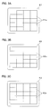
図2に示すように、蛍光体ホイール35は、円板状の基板35a上に環状の蛍光体41を固定したものであり、図1に示す駆動部39に駆動されて軸RXのまわりに定速で回転する。蛍光体41は、励起光ELの吸収によって、それより波長の長い蛍光を発する。蛍光体41は、励起光ELの照射によって緑蛍光を発生する緑領域AR1と、励起光ELの照射によって赤蛍光を発生する赤領域AR2と、励起光ELを若干散乱させつつ反射する散乱面である青領域AR3とを有する。青領域AR3では、偏光状態をあまり変化させないことが望ましい。
As shown in FIG. 2, the phosphor wheel 35 is obtained by fixing an annular phosphor 41 on a disk-shaped substrate 35a, and is driven around the axis RX by being driven by the drive unit 39 shown in FIG. Rotates at high speed. The phosphor 41 emits fluorescence having a longer wavelength by absorption of the excitation light EL. The phosphor 41 has a green area AR1 that generates green fluorescence when irradiated with the excitation light EL, a red area AR2 that generates red fluorescence when irradiated with the excitation light EL, and a scattering surface that reflects and reflects the excitation light EL slightly. It has a certain blue area AR3. In the blue region AR3, it is desirable not to change the polarization state so much.
フライアイ光学系36は、励起光ELの強度分布を均一化する第1均一化系36aと、蛍光FLの強度分布を均一化する第2均一化系36bとを備える。励起光EL用の第1均一化系36aは、偏光ダイクロイックミラー32のレーザーアレイ(励起光源)51側に配置される第1フライアイレンズ61と、偏光ダイクロイックミラー32と蛍光体41との間の光路に配置される第2フライアイレンズ62とを含む。蛍光FL用の第2均一化系36bは、偏光ダイクロイックミラー32と蛍光体41との間の光路に配置される第2フライアイレンズ62と、偏光ダイクロイックミラー32の蛍光FLが射出される側に配置される第3フライアイレンズ63とを含む。つまり、第2フライアイレンズ62は、励起光EL及び蛍光FLの双方の強度分布の均一化に兼用されている。また、第1フライアイレンズ61は、励起光ELの強度分布の均一化に寄与し、第3フライアイレンズ63は、蛍光FL及び青の反射励起光の強度分布の均一化に寄与する。第1フライアイレンズ61は、図3Aに示すように、励起光ELを分割するための要素として複数のレンズ61aを含む。第2フライアイレンズ62は、図3Bに示すように、励起光ELを適度に発散させるとともに蛍光FLを分割するための要素として複数のレンズ62aを含む。第3フライアイレンズ63は、図3Cに示すように、蛍光FL等を適度に発散させるための要素として複数のレンズ63aを含む。第1フライアイレンズ61を構成するレンズ61a、第2フライアイレンズ62を構成するレンズ62a、及び第3フライアイレンズ63を構成するレンズ63aの各々は、互いに隣り合って2次元配置されている。
The fly's eye optical system 36 includes a first homogenizing system 36a that equalizes the intensity distribution of the excitation light EL and a second homogenizing system 36b that equalizes the intensity distribution of the fluorescence FL. The first homogenization system 36a for the excitation light EL includes a first fly-eye lens 61 disposed on the laser array (excitation light source) 51 side of the polarization dichroic mirror 32, and between the polarization dichroic mirror 32 and the phosphor 41. And a second fly-eye lens 62 disposed in the optical path. The second homogenization system 36b for the fluorescence FL is disposed on the side where the fluorescence FL of the second fly-eye lens 62 disposed in the optical path between the polarization dichroic mirror 32 and the phosphor 41 and the polarization dichroic mirror 32 is emitted. And a third fly-eye lens 63 disposed. That is, the second fly's eye lens 62 is also used to make the intensity distribution of both the excitation light EL and the fluorescence FL uniform. The first fly-eye lens 61 contributes to the uniform distribution of the intensity of the excitation light EL, and the third fly-eye lens 63 contributes to the uniform distribution of the intensity distribution of the fluorescent light FL and the blue reflected excitation light. As shown in FIG. 3A, the first fly-eye lens 61 includes a plurality of lenses 61a as elements for dividing the excitation light EL. As shown in FIG. 3B, the second fly-eye lens 62 includes a plurality of lenses 62a as elements for appropriately diverging the excitation light EL and dividing the fluorescence FL. As shown in FIG. 3C, the third fly-eye lens 63 includes a plurality of lenses 63a as elements for appropriately diverging the fluorescence FL and the like. The lens 61a constituting the first fly-eye lens 61, the lens 62a constituting the second fly-eye lens 62, and the lens 63a constituting the third fly-eye lens 63 are two-dimensionally arranged adjacent to each other. .
第1均一化系36aによる励起光ELの強度分布の均一化について説明する。第1フライアイレンズ61には、励起光ELが入射して複数の光線に分割される。第1フライアイレンズ61を構成する1つのレンズ61aから射出された励起光ELaは、レンズ61aによって収束される。レンズ61aからの励起光ELaは、第2フライアイレンズ62の対応するレンズ62aに入射して発散しつつコンデンサーレンズ34に入射する。コンデンサーレンズ34は、第2フライアイレンズ62を構成する各レンズ62aからの励起光ELaを、蛍光体41の矩形の有効領域に少ないズレで重畳するように入射させる。結果的に、蛍光体41の矩形の有効領域は、均一化された励起光ELaすなわち励起光ELによって無駄なく照明される。なお、第2フライアイレンズ62には、励起光ELaの発散角度を変化させる機能だけでなく、励起光ELaの射出方向を調整する機能を持たせることができる。
The homogenization of the intensity distribution of the excitation light EL by the first homogenization system 36a will be described. The excitation light EL enters the first fly's eye lens 61 and is divided into a plurality of light beams. The excitation light ELa emitted from one lens 61a constituting the first fly-eye lens 61 is converged by the lens 61a. The excitation light ELa from the lens 61a enters the corresponding lens 62a of the second fly-eye lens 62 and enters the condenser lens 34 while diverging. The condenser lens 34 causes the excitation light ELa from each lens 62 a constituting the second fly-eye lens 62 to be incident on the rectangular effective area of the phosphor 41 so as to be superimposed with a small deviation. As a result, the rectangular effective area of the phosphor 41 is illuminated without waste by the uniform excitation light ELa, that is, the excitation light EL. Note that the second fly's eye lens 62 can have not only a function of changing the divergence angle of the excitation light ELa but also a function of adjusting the emission direction of the excitation light ELa.
第2均一化系36bによる蛍光FL及び青色光(反射励起光)の強度分布に均一化について説明する。なお、青色光(反射励起光)は、蛍光FLと同様に均一化されるので、以下では蛍光FLの説明によってその説明を省略する。第2フライアイレンズ62を構成するレンズ62aの各々は、反射型液晶素子23の画像表示領域と略相似した形状を有している。図3Bにおいて、レンズ62aはマトリクス状に配置されているが、千鳥配置されていれもよい。第2フライアイレンズ62には、コンデンサーレンズ34によってコリメートされた蛍光FLが上記励起光ELと逆方向から入射して複数の光線に分割される。第2フライアイレンズ62を構成する1つのレンズ62aから射出された蛍光FLaは、レンズ62aによって収束される。レンズ62aからの蛍光FLaは、第3フライアイレンズ63の対応するレンズ63aに入射して一旦2次光源を形成するとともに適度に発散しつつ偏光変換部37に入射する。なお、第3フライアイレンズ63には、蛍光FLaの発散角度を変化させる機能だけでなく、蛍光FLaの射出方向を調整する機能を持たせることができる。
The homogenization of the intensity distribution of the fluorescence FL and the blue light (reflection excitation light) by the second homogenization system 36b will be described. In addition, since blue light (reflected excitation light) is equalized similarly to fluorescence FL, the description is abbreviate | omitted by description of fluorescence FL below. Each of the lenses 62 a constituting the second fly-eye lens 62 has a shape substantially similar to the image display area of the reflective liquid crystal element 23. In FIG. 3B, the lenses 62a are arranged in a matrix, but may be arranged in a staggered manner. The fluorescent light collimated by the condenser lens 34 enters the second fly-eye lens 62 from the opposite direction to the excitation light EL and is divided into a plurality of light beams. The fluorescence FLa emitted from one lens 62a constituting the second fly's eye lens 62 is converged by the lens 62a. The fluorescent light FLa from the lens 62a enters the corresponding lens 63a of the third fly's eye lens 63 to once form a secondary light source and enter the polarization conversion unit 37 while being appropriately diverged. Note that the third fly's eye lens 63 can have not only a function of changing the divergence angle of the fluorescence FLa but also a function of adjusting the emission direction of the fluorescence FLa.
以上のように、レーザーアレイ(励起光源)51は、励起光ELとして青色光を出射し、蛍光体41は、青色光による励起によって発生した蛍光を放射し、フライアイ光学系36は、励起光ELの強度分布と蛍光FLの強度分布とをそれぞれ均一化する。これにより、青色光と蛍光FLとを含む照明光L2を得ることができる。
As described above, the laser array (excitation light source) 51 emits blue light as the excitation light EL, the phosphor 41 emits fluorescence generated by excitation with blue light, and the fly-eye optical system 36 generates excitation light. The EL intensity distribution and the fluorescence FL intensity distribution are made uniform. Thereby, the illumination light L2 containing blue light and fluorescence FL can be obtained.
偏光変換部37は、第3フライアイレンズ63の光射出側に配置されて、励起光ELから得た照明光L2の偏光方向を揃えるものである。これにより、照明光L2の偏光方向を所望の方向に揃えて照明対象、具体的には光変調素子等である反射型液晶素子23に入射させることができる。偏光変換部37は、例えば偏光ビームスプリッターや波長板からなる変換ユニットを複数組み合わせたものであり、偏光ダイクロイックミラー32で反射された蛍光FLaや青色光に含まれるS偏光及びP偏光のうちP偏光のみを選択的にS偏光に変換する。これにより、偏光ビームスプリッター22に略S偏光の蛍光FL(すなわち緑色光及び赤色光)を入射させることができ、光源光のロスが少なくなる。なお、励起光ELから得た青色光(反射励起光)は、偏光ダイクロイックミラー32で反射されたS偏光成分のみであり、偏光変換部37を略そのまま通過する。
The polarization conversion unit 37 is arranged on the light exit side of the third fly-eye lens 63, and aligns the polarization direction of the illumination light L2 obtained from the excitation light EL. Thereby, the polarization direction of the illumination light L2 can be aligned in a desired direction and can be incident on the reflective liquid crystal element 23, which is an illumination target, specifically, a light modulation element or the like. The polarization conversion unit 37 is a combination of a plurality of conversion units including, for example, a polarization beam splitter and a wave plate, and is P-polarized light among S-polarized light and P-polarized light included in the fluorescent light FLa and blue light reflected by the polarization dichroic mirror 32. Are selectively converted to S-polarized light. As a result, substantially S-polarized fluorescence FL (that is, green light and red light) can be made incident on the polarization beam splitter 22, and the loss of the light source light is reduced. Note that the blue light (reflected excitation light) obtained from the excitation light EL is only the S-polarized light component reflected by the polarization dichroic mirror 32 and passes through the polarization conversion unit 37 almost as it is.
フィールドレンズ38は、反射型液晶素子23上において光軸SXに近い領域と光軸SXから離れた領域とにおける光線の進行方向を調和させるためのものであり、反射型液晶素子23上において照明光L2を均一に重畳させ照明光L2の入射角範囲を一様にする働きを有する。
The field lens 38 is for harmonizing the traveling direction of light beams in a region close to the optical axis SX and a region away from the optical axis SX on the reflective liquid crystal element 23, and illumination light on the reflective liquid crystal element 23. L2 is uniformly superimposed and has a function of making the incident angle range of the illumination light L2 uniform.
以上で説明した第1実施形態の光源装置21によれば、偏光ダイクロイックミラー32と蛍光体41との間の光路にフライアイ光学系36の一部である第2フライアイレンズ62が配置されることにより、励起光EL及び蛍光FLを2度通過させる。第2フライアイレンズ62を含む第1均一化系36aにより、蛍光体41の有効領域を励起光ELによって均一に照明することができる。また、第2フライアイレンズ62を含む第2均一化系36bにより、蛍光FLの強度分布を均一化して反射型液晶素子23を均一に照明することができる。フライアイ光学系36の一部である第2フライアイレンズ62が偏光ダイクロイックミラー32と蛍光体41との間の光路に配置されて励起光EL及び蛍光FLの双方の強度分布の均一化に兼用されるので、励起光用のフライアイ光学系と蛍光用のフライアイ光学系とを個別に設ける場合に比較して、光源装置21の光学系のサイズやコストを抑えることができる。
According to the light source device 21 of the first embodiment described above, the second fly's eye lens 62 that is a part of the fly's eye optical system 36 is disposed in the optical path between the polarization dichroic mirror 32 and the phosphor 41. Thus, the excitation light EL and the fluorescence FL are passed twice. The effective area of the phosphor 41 can be uniformly illuminated by the excitation light EL by the first homogenizing system 36a including the second fly-eye lens 62. Further, the second uniformizing system 36b including the second fly-eye lens 62 can uniformly illuminate the reflective liquid crystal element 23 by uniformizing the intensity distribution of the fluorescence FL. A second fly-eye lens 62, which is a part of the fly-eye optical system 36, is disposed in the optical path between the polarization dichroic mirror 32 and the phosphor 41, and is also used to equalize the intensity distribution of both the excitation light EL and the fluorescence FL. Therefore, the size and cost of the optical system of the light source device 21 can be reduced as compared with the case where the fly-eye optical system for excitation light and the fly-eye optical system for fluorescence are provided separately.
また、投影装置2は、上述のように、小型で効率的な光源装置21を用いており、小型で明るいものとすることができる。
Further, as described above, the projection device 2 uses the small and efficient light source device 21 and can be small and bright.
〔第2実施形態〕
以下、第2実施形態に係る光源装置について説明する。なお、第2実施形態の光源装置は第1実施形態の光源装置を変形したものであり、特に説明しない事項は第1実施形態と同様である。 [Second Embodiment]
The light source device according to the second embodiment will be described below. The light source device according to the second embodiment is a modification of the light source device according to the first embodiment, and matters not specifically described are the same as those in the first embodiment.
図4Aに示すように、第2実施形態の光源装置21の場合、レーザーアレイ151は、励起用のレーザー光L1として、例えば440nm以下(紫外光又は青紫光)の光を発生する。
As shown in FIG. 4A, in the case of the light source device 21 of the second embodiment, the laser array 151 generates, for example, light of 440 nm or less (ultraviolet light or blue-violet light) as the excitation laser light L1.
図4Bに示すように、蛍光体ホイール35において、蛍光体141は、励起光ELの照射によって緑蛍光を発生する緑領域AR1と、励起光ELの照射によって赤蛍光を発生する赤領域AR2と、励起光ELの照射によって励起光ELより波長の長い青蛍光を発生する青領域AR3とを有する。
As shown in FIG. 4B, in the phosphor wheel 35, the phosphor 141 includes a green region AR1 that generates green fluorescence when irradiated with the excitation light EL, a red region AR2 that generates red fluorescence when irradiated with the excitation light EL, A blue region AR3 that generates blue fluorescence having a wavelength longer than that of the excitation light EL when irradiated with the excitation light EL.
以上の第2実施形態では、偏光ダイクロイックミラー32に代えて、紫外光又は青紫の波長帯域の励起光ELを透過させ、それより波長が長い可視光を選択的に反射するダイクロイックミラー132が用いられている。ダイクロイックミラー132は、色離型のビームスプリッターである。この場合、励起光EL等の偏光状態を制御する必要が無くなり、図1に示す位相差板33は不要となる。ここでは、ダイクロイックミラー132が、励起光源(レーザーアレイ151)と蛍光体141との間の光路に配置され、蛍光FLを励起光ELの光路から分岐するビームスプリッターに相当する。
In the second embodiment described above, instead of the polarization dichroic mirror 32, a dichroic mirror 132 that transmits excitation light EL in the ultraviolet or blue-violet wavelength band and selectively reflects visible light having a longer wavelength is used. ing. The dichroic mirror 132 is a color separation type beam splitter. In this case, it is not necessary to control the polarization state of the excitation light EL or the like, and the phase difference plate 33 shown in FIG. 1 is not necessary. Here, the dichroic mirror 132 is disposed in the optical path between the excitation light source (laser array 151) and the phosphor 141, and corresponds to a beam splitter that branches the fluorescence FL from the optical path of the excitation light EL.
〔第3実施形態〕
以下、第3実施形態に係る投影装置について説明する。なお、第3実施形態の投影装置は第1実施形態の投影装置を変形したものであり、特に説明しない事項は第1実施形態と同様である。 [Third Embodiment]
The projector according to the third embodiment will be described below. The projection apparatus according to the third embodiment is a modification of the projection apparatus according to the first embodiment, and matters not specifically described are the same as those in the first embodiment.
図5に示すように、第3実施形態の光源装置21は、フライアイ光学系136として、偏光ダイクロイックミラー32と蛍光体41との間の光路のみにフライアイレンズ162を配置したものである。これにより、フライアイ光学系136を、より省スペースで配置することができ、光源装置21、延いては投影装置2をより小型化できる。フライアイレンズ162は、励起光EL及び蛍光FLの双方の強度分布の均一化に兼用され、励起光EL及び蛍光FLを分割するための要素として複数のレンズ162aを含む。
As shown in FIG. 5, the light source device 21 of the third embodiment has a fly-eye optical system 136 in which a fly-eye lens 162 is disposed only in the optical path between the polarization dichroic mirror 32 and the phosphor 41. As a result, the fly-eye optical system 136 can be arranged in a smaller space, and the light source device 21, and thus the projection device 2, can be further downsized. The fly-eye lens 162 is used to make the intensity distribution of both the excitation light EL and the fluorescence FL uniform, and includes a plurality of lenses 162a as elements for dividing the excitation light EL and the fluorescence FL.
フライアイレンズ162のレーザーアレイ51側のアレイ面62iは、励起光ELに関して第1実施形態の第1フライアイレンズ61と同様の機能を有するものであり、励起光ELを分割する。フライアイレンズ162の蛍光体41側のアレイ面62oは、励起光ELに関して第1実施形態の第2フライアイレンズ62と同様の機能を有するものであり、分割された励起光ELaを適度に発散させる。なお、フライアイレンズ162の蛍光体41側のアレイ面62oには、分割された励起光ELaの発散角度を変化させる機能だけでなく、励起光ELaの射出方向を調整する機能を持たせることができる。
The array surface 62i on the laser array 51 side of the fly-eye lens 162 has the same function as the first fly-eye lens 61 of the first embodiment with respect to the excitation light EL, and divides the excitation light EL. The array surface 62o on the phosphor 41 side of the fly-eye lens 162 has the same function as the second fly-eye lens 62 of the first embodiment with respect to the excitation light EL, and appropriately divides the divided excitation light ELa. Let The array surface 62o on the phosphor 41 side of the fly-eye lens 162 may have not only a function of changing the divergence angle of the divided excitation light ELa but also a function of adjusting the emission direction of the excitation light ELa. it can.
また、フライアイレンズ162の蛍光体41側のアレイ面62oは、蛍光FLに関して第1実施形態の第2フライアイレンズ62と同様の機能を有するものであり、蛍光FLを分割する。フライアイレンズ162のレーザーアレイ51側のアレイ面62iは、蛍光FLに関して第1実施形態の第3フライアイレンズ63と同様の機能を有するものであり、分割された蛍光FLaを適度に発散させる。
The array surface 62o on the phosphor 41 side of the fly-eye lens 162 has the same function as the second fly-eye lens 62 of the first embodiment with respect to the fluorescence FL, and divides the fluorescence FL. The array surface 62i on the laser array 51 side of the fly-eye lens 162 has a function similar to that of the third fly-eye lens 63 of the first embodiment with respect to the fluorescence FL, and appropriately divides the divided fluorescence FLa.
図5に示す光源装置21は、偏光変換部37を有していない。このため、第3実施形態の場合、偏光ビームスプリッター22や反射型液晶素子23に代えてデジタルマイクロミラーデバイス123が用いられている。なお、デジタルマイクロミラーデバイス123から得られる画像を拡大してスクリーン等に投影する投影光学系については図示を省略している。なお、図5では、両面にレンズ面が形成された単一のフライアイレンズを配置しているが、これに限らず、複数枚のフライアイレンズを配置してもよい。
5 does not have the polarization conversion unit 37. The light source device 21 shown in FIG. Therefore, in the case of the third embodiment, a digital micromirror device 123 is used instead of the polarization beam splitter 22 and the reflective liquid crystal element 23. Note that a projection optical system that enlarges an image obtained from the digital micromirror device 123 and projects it on a screen or the like is not shown. In FIG. 5, a single fly-eye lens having lens surfaces formed on both sides is disposed. However, the present invention is not limited to this, and a plurality of fly-eye lenses may be disposed.
デジタルマイクロミラーデバイス123は、画素に対応するとともに傾斜可能な多数のミラーを2次元的に配列したものであり、偏光ダイクロイックミラー32からフィールドレンズ38を介して入射した照明光L2を不図示の投影光学系に向けたり投影光学系から逸らしたりするオン・オフ動作が可能である。
The digital micromirror device 123 is a two-dimensional array of a large number of mirrors that correspond to pixels and can be tilted, and projects illumination light L2 incident from the polarization dichroic mirror 32 via the field lens 38 (not shown). An on / off operation that is directed toward the optical system or deviates from the projection optical system is possible.
以上、実施形態に係る光源装置及び投影装置について説明したが、本発明に係る光源装置等は、上記のものには限られない。例えば、光源装置21や投影光学系24の具体的な構成は、図示のものに限らず用途等に応じて適宜変更することができる。
Although the light source device and the projection device according to the embodiment have been described above, the light source device and the like according to the present invention are not limited to the above. For example, the specific configurations of the light source device 21 and the projection optical system 24 are not limited to those shown in the drawings, and can be changed as appropriate according to the application.
例えば、レーザービーム形成部31において、レーザーアレイ51に代えてLEDアレイを用いることもできる。LEDアレイからの光を照明光として用いる場合、LEDアレイからの光の偏光方向を偏光ダイクロイックミラー32への入射前に揃えることが望ましい。
For example, in the laser beam forming unit 31, an LED array can be used instead of the laser array 51. When using light from the LED array as illumination light, it is desirable to align the polarization direction of the light from the LED array before entering the polarization dichroic mirror 32.
また、コンデンサーレンズ34、第2フライアイレンズ62、蛍光体41,141等は、偏光ダイクロイックミラー32の反射側に設けることができる。この場合、偏光ダイクロイックミラー32において、S偏光である励起光ELを反射し、励起光ELで照明された蛍光体41,141で発生した緑色光、赤色光等を透過させる。
Further, the condenser lens 34, the second fly-eye lens 62, the phosphors 41, 141, and the like can be provided on the reflection side of the polarization dichroic mirror 32. In this case, the polarization dichroic mirror 32 reflects the excitation light EL that is S-polarized light, and transmits green light, red light, and the like generated by the phosphors 41 and 141 illuminated by the excitation light EL.
画像表示素子として、反射型液晶素子23に代えて透過型の液晶素子を用いてもよい。
As the image display element, a transmissive liquid crystal element may be used instead of the reflective liquid crystal element 23.
蛍光体41又は蛍光体ホイール35において、青領域AR3を、散乱面とせず単なる反射面とすることができ、この場合、例えばコリメーターアレイ52を不完全にして光を拡散するといった手法を用いることができる。
In the phosphor 41 or the phosphor wheel 35, the blue region AR3 can be a simple reflecting surface instead of a scattering surface. In this case, for example, a method of diffusing light with the collimator array 52 incomplete is used. Can do.
Claims (9)
- 励起光を射出する励起光源と、
励起光が照射されることによって蛍光を放射する蛍光体と、
前記励起光源と前記蛍光体との間の光路に配置され、蛍光を励起光の光路から分岐するビームスプリッターと、
励起光の強度分布及び蛍光の強度分布を均一化するフライアイ光学系と、を有し
前記ビームスプリッターと前記蛍光体との間の光路に前記フライアイ光学系の少なくとも一部が配置されている投影装置用の光源装置。 An excitation light source that emits excitation light;
A phosphor that emits fluorescence when irradiated with excitation light; and
A beam splitter that is arranged in an optical path between the excitation light source and the phosphor, and branches the fluorescence from the optical path of the excitation light;
A fly-eye optical system that equalizes the intensity distribution of excitation light and the intensity distribution of fluorescence, and at least part of the fly-eye optical system is disposed in an optical path between the beam splitter and the phosphor A light source device for a projection device. - 前記フライアイ光学系は、前記ビームスプリッターの前記励起光源側に配置される第1フライアイレンズと、前記ビームスプリッターと前記蛍光体との間の光路に配置される第2フライアイレンズと、前記ビームスプリッターの蛍光が射出される側に配置される第3フライアイレンズとを備える、請求項1に記載の投影装置用の光源装置。 The fly-eye optical system includes a first fly-eye lens disposed on the excitation light source side of the beam splitter, a second fly-eye lens disposed in an optical path between the beam splitter and the phosphor, The light source device for a projection device according to claim 1, further comprising a third fly's eye lens disposed on a beam splitter side on which the fluorescence is emitted.
- 前記第3フライアイレンズの光射出側に配置されて偏光方向を揃える偏光変換部をさらに備える、請求項2に記載の投影装置用の光源装置。 The light source device for a projection device according to claim 2, further comprising a polarization conversion unit that is disposed on a light exit side of the third fly-eye lens and aligns the polarization direction.
- 前記フライアイ光学系は、前記ビームスプリッターと前記蛍光体との間の光路にのみ配置されている、請求項1に記載の投影装置用の光源装置。 The light source device for a projection device according to claim 1, wherein the fly-eye optical system is disposed only in an optical path between the beam splitter and the phosphor.
- 前記励起光源は、励起光として青色光を射出し、前記蛍光体は、青色光による励起によって発生した蛍光を放射し、前記フライアイ光学系は、励起光の強度分布と蛍光の強度分布とをそれぞれ均一化する、請求項1~4のいずれか一項に記載の投影装置用の光源装置。 The excitation light source emits blue light as excitation light, the phosphor emits fluorescence generated by excitation with blue light, and the fly-eye optical system performs excitation light intensity distribution and fluorescence intensity distribution. The light source device for a projection device according to any one of claims 1 to 4, wherein each of the light source devices is uniformized.
- 前記ビームスプリッターは、位相差板と組み合わせて用いられ、特定方向の偏光である青色光を透過及び反射の別によって光路的に分岐する偏光ダイクロイックミラーであり、前記励起光源からの青色光を前記蛍光体に導くとともに、前記蛍光体で励起に利用されなかった青色光を蛍光の光路に導く、請求項5に記載の投影装置用の光源装置。 The beam splitter is a polarization dichroic mirror that is used in combination with a phase difference plate and splits blue light, which is polarized light in a specific direction, on the optical path depending on whether it is transmitted or reflected, and converts the blue light from the excitation light source into the fluorescent light. 6. The light source device for a projection device according to claim 5, wherein the light source device for the projection device according to claim 5, wherein the light source device guides blue light that has not been used for excitation by the phosphor to a fluorescent light path.
- 前記励起光源は、励起光として紫外光又は青紫光を射出し、前記蛍光体は、可視域の蛍光を放射し、前記フライアイ光学系は、励起光の強度分布と蛍光の強度分布とをそれぞれ均一化する、請求項1~4のいずれか一項に記載の投影装置用の光源装置。 The excitation light source emits ultraviolet light or blue-violet light as excitation light, the phosphor emits fluorescence in the visible range, and the fly-eye optical system performs excitation light intensity distribution and fluorescence intensity distribution, respectively. The light source device for a projection device according to any one of claims 1 to 4, wherein the light source device is uniformized.
- 請求項1~7のいずれか一項に記載の投影装置用の光源装置と、
前記光源装置によって照明される画像表示素子と、
前記画像表示素子により形成される画像を投影する投影光学系と、
を有する投影装置。 A light source device for a projection device according to any one of claims 1 to 7,
An image display element illuminated by the light source device;
A projection optical system for projecting an image formed by the image display element;
A projection apparatus. - 前記光源装置は、円板状の基板に前記蛍光体が固定された蛍光体ホイールを備え、
前記蛍光体ホイールは、その周方向に互いに異なる波長の蛍光を発する複数の領域が形成されており、
前記蛍光体ホイールの回転に同期して、前記複数の領域から発せられる蛍光の波長に対応した前記画像表示素子に表示される画像を切り替える制御部を備える、請求項8に記載の投影装置。 The light source device includes a phosphor wheel in which the phosphor is fixed to a disk-shaped substrate,
The phosphor wheel is formed with a plurality of regions emitting fluorescence of different wavelengths in the circumferential direction,
The projection apparatus according to claim 8, further comprising: a control unit that switches an image displayed on the image display element corresponding to a wavelength of fluorescence emitted from the plurality of regions in synchronization with rotation of the phosphor wheel.
Applications Claiming Priority (2)
| Application Number | Priority Date | Filing Date | Title |
|---|---|---|---|
| JP2015-055456 | 2015-03-18 | ||
| JP2015055456 | 2015-03-18 |
Publications (1)
| Publication Number | Publication Date |
|---|---|
| WO2016148210A1 true WO2016148210A1 (en) | 2016-09-22 |
Family
ID=56919186
Family Applications (1)
| Application Number | Title | Priority Date | Filing Date |
|---|---|---|---|
| PCT/JP2016/058401 WO2016148210A1 (en) | 2015-03-18 | 2016-03-16 | Light source device and projection device |
Country Status (1)
| Country | Link |
|---|---|
| WO (1) | WO2016148210A1 (en) |
Cited By (6)
| Publication number | Priority date | Publication date | Assignee | Title |
|---|---|---|---|---|
| EP3712701A1 (en) * | 2019-03-18 | 2020-09-23 | Ricoh Company, Ltd. | Light source optical system, light source device, and image projection apparatus |
| CN113063759A (en) * | 2021-03-15 | 2021-07-02 | 国科大杭州高等研究院 | Somatic cell laser-induced fluorescence detection method based on hemispherical space compound eye structure |
| CN113063762A (en) * | 2021-03-15 | 2021-07-02 | 国科大杭州高等研究院 | Laser-induced fluorescence detector for hemispheric space compound eye somatic cells |
| WO2021181737A1 (en) * | 2020-03-09 | 2021-09-16 | パナソニックIpマネジメント株式会社 | Fluorescence excitation light source device |
| CN114563908A (en) * | 2018-09-20 | 2022-05-31 | 深圳光峰科技股份有限公司 | Light source system and projection equipment |
| CN116540487A (en) * | 2023-05-16 | 2023-08-04 | 合肥全色光显科技有限公司 | Dodging system of double fly-eye lens system |
Citations (11)
| Publication number | Priority date | Publication date | Assignee | Title |
|---|---|---|---|---|
| WO2012042563A1 (en) * | 2010-09-29 | 2012-04-05 | 日立コンシューマエレクトロニクス株式会社 | Projector image displaying device |
| JP2012123179A (en) * | 2010-12-08 | 2012-06-28 | Seiko Epson Corp | Light source device and projector |
| JP2012137744A (en) * | 2010-12-06 | 2012-07-19 | Panasonic Corp | Light source device and projection type display device |
| JP2012189938A (en) * | 2011-03-14 | 2012-10-04 | Seiko Epson Corp | Light source device and projector |
| JP2012234161A (en) * | 2011-04-20 | 2012-11-29 | Panasonic Corp | Light source apparatus and image display apparatus |
| JP2013008950A (en) * | 2011-05-23 | 2013-01-10 | Panasonic Corp | Light source device and image display apparatus |
| JP2013156639A (en) * | 2013-02-25 | 2013-08-15 | Casio Comput Co Ltd | Projection device |
| JP2013190674A (en) * | 2012-03-14 | 2013-09-26 | Seiko Epson Corp | Projector |
| JP2014010181A (en) * | 2012-06-27 | 2014-01-20 | Ricoh Co Ltd | Light source device and projecting device |
| JP2014026195A (en) * | 2012-07-30 | 2014-02-06 | Seiko Epson Corp | Light source device and projector |
| JP2014191248A (en) * | 2013-03-28 | 2014-10-06 | Seiko Epson Corp | Illumination apparatus and projector |
-
2016
- 2016-03-16 WO PCT/JP2016/058401 patent/WO2016148210A1/en active Application Filing
Patent Citations (11)
| Publication number | Priority date | Publication date | Assignee | Title |
|---|---|---|---|---|
| WO2012042563A1 (en) * | 2010-09-29 | 2012-04-05 | 日立コンシューマエレクトロニクス株式会社 | Projector image displaying device |
| JP2012137744A (en) * | 2010-12-06 | 2012-07-19 | Panasonic Corp | Light source device and projection type display device |
| JP2012123179A (en) * | 2010-12-08 | 2012-06-28 | Seiko Epson Corp | Light source device and projector |
| JP2012189938A (en) * | 2011-03-14 | 2012-10-04 | Seiko Epson Corp | Light source device and projector |
| JP2012234161A (en) * | 2011-04-20 | 2012-11-29 | Panasonic Corp | Light source apparatus and image display apparatus |
| JP2013008950A (en) * | 2011-05-23 | 2013-01-10 | Panasonic Corp | Light source device and image display apparatus |
| JP2013190674A (en) * | 2012-03-14 | 2013-09-26 | Seiko Epson Corp | Projector |
| JP2014010181A (en) * | 2012-06-27 | 2014-01-20 | Ricoh Co Ltd | Light source device and projecting device |
| JP2014026195A (en) * | 2012-07-30 | 2014-02-06 | Seiko Epson Corp | Light source device and projector |
| JP2013156639A (en) * | 2013-02-25 | 2013-08-15 | Casio Comput Co Ltd | Projection device |
| JP2014191248A (en) * | 2013-03-28 | 2014-10-06 | Seiko Epson Corp | Illumination apparatus and projector |
Cited By (12)
| Publication number | Priority date | Publication date | Assignee | Title |
|---|---|---|---|---|
| CN114563908A (en) * | 2018-09-20 | 2022-05-31 | 深圳光峰科技股份有限公司 | Light source system and projection equipment |
| CN114563908B (en) * | 2018-09-20 | 2024-04-05 | 深圳光峰科技股份有限公司 | Light source system and projection device |
| EP3712701A1 (en) * | 2019-03-18 | 2020-09-23 | Ricoh Company, Ltd. | Light source optical system, light source device, and image projection apparatus |
| JP2020154024A (en) * | 2019-03-18 | 2020-09-24 | 株式会社リコー | Light source optical system, light source device, and image projection device |
| US10942434B2 (en) | 2019-03-18 | 2021-03-09 | Ricoh Company, Ltd. | Light source optical system, light source device, and image projection apparatus |
| US11314157B2 (en) | 2019-03-18 | 2022-04-26 | Ricoh Company, Ltd. | Light source optical system, light source device, and image projection apparatus |
| JP7268421B2 (en) | 2019-03-18 | 2023-05-08 | 株式会社リコー | Light source optical system, light source device and image projection device |
| EP4198629A1 (en) * | 2019-03-18 | 2023-06-21 | Ricoh Company, Ltd. | Light source optical system, light source device, and image projection apparatus |
| WO2021181737A1 (en) * | 2020-03-09 | 2021-09-16 | パナソニックIpマネジメント株式会社 | Fluorescence excitation light source device |
| CN113063759A (en) * | 2021-03-15 | 2021-07-02 | 国科大杭州高等研究院 | Somatic cell laser-induced fluorescence detection method based on hemispherical space compound eye structure |
| CN113063762A (en) * | 2021-03-15 | 2021-07-02 | 国科大杭州高等研究院 | Laser-induced fluorescence detector for hemispheric space compound eye somatic cells |
| CN116540487A (en) * | 2023-05-16 | 2023-08-04 | 合肥全色光显科技有限公司 | Dodging system of double fly-eye lens system |
Similar Documents
| Publication | Publication Date | Title |
|---|---|---|
| US9407886B2 (en) | Illumination optical system and projector including fluorophore | |
| CN107608166B (en) | Light source device and projection display device | |
| JP6056001B2 (en) | Light source device and projection display device | |
| WO2016148210A1 (en) | Light source device and projection device | |
| TWI595306B (en) | A color combiner and an image projector | |
| US10819961B2 (en) | Light source apparatus for use in projection three-dimensional display apparatus, with dynamic diffusion plate | |
| US10627710B2 (en) | Light source apparatus and projector | |
| US9389427B2 (en) | Optical system and projection display apparatus using the same | |
| US10599025B2 (en) | Light source device and projector | |
| US9804486B2 (en) | Light source apparatus, illuminator, and projector having multiple reflection elements | |
| US11669001B2 (en) | Projection display system | |
| CN108388021B (en) | Polarization conversion element and projector | |
| KR20170133936A (en) | Light source device and projector comprising the same | |
| US11156825B2 (en) | Projector | |
| WO2017018372A1 (en) | Light source device and projection device | |
| JP2015108830A (en) | Illumination optical system including phosphor, projector, and irradiation method | |
| US10271025B2 (en) | Color separating and combining system and projecting display apparatus including the same | |
| JP2016194699A (en) | Illumination optical system equipped with phosphor and projector | |
| JP2010113186A (en) | Projection type display device | |
| WO2023058587A1 (en) | Light source device and projection-type video display device | |
| JP2017181602A (en) | Light source unit | |
| JP2017090816A (en) | Illumination device and projector | |
| JP2007272231A (en) | Projection system and method | |
| JP2005031436A (en) | Lighting device and projector having the same |
Legal Events
| Date | Code | Title | Description |
|---|---|---|---|
| 121 | Ep: the epo has been informed by wipo that ep was designated in this application |
Ref document number: 16765039 Country of ref document: EP Kind code of ref document: A1 |
|
| NENP | Non-entry into the national phase |
Ref country code: DE |
|
| 122 | Ep: pct application non-entry in european phase |
Ref document number: 16765039 Country of ref document: EP Kind code of ref document: A1 |
|
| NENP | Non-entry into the national phase |
Ref country code: JP |