EP3709470B1 - Induktiver stromsender - Google Patents
Induktiver stromsender Download PDFInfo
- Publication number
- EP3709470B1 EP3709470B1 EP20173240.1A EP20173240A EP3709470B1 EP 3709470 B1 EP3709470 B1 EP 3709470B1 EP 20173240 A EP20173240 A EP 20173240A EP 3709470 B1 EP3709470 B1 EP 3709470B1
- Authority
- EP
- European Patent Office
- Prior art keywords
- frequencies
- coil
- transmitter
- inductance
- frequency
- Prior art date
- Legal status (The legal status is an assumption and is not a legal conclusion. Google has not performed a legal analysis and makes no representation as to the accuracy of the status listed.)
- Active
Links
Images

Classifications
-
- H—ELECTRICITY
- H02—GENERATION; CONVERSION OR DISTRIBUTION OF ELECTRIC POWER
- H02J—ELECTRIC POWER NETWORKS; CIRCUIT ARRANGEMENTS OR SYSTEMS FOR SUPPLYING OR DISTRIBUTING ELECTRIC POWER; SYSTEMS FOR STORING ELECTRIC ENERGY
- H02J50/00—Circuit arrangements or systems for wireless supply or distribution of electric power
- H02J50/005—Mechanical details of housing or structure aiming to accommodate the power transfer means, e.g. mechanical integration of coils, antennas or transducers into emitting or receiving devices
-
- H—ELECTRICITY
- H02—GENERATION; CONVERSION OR DISTRIBUTION OF ELECTRIC POWER
- H02J—ELECTRIC POWER NETWORKS; CIRCUIT ARRANGEMENTS OR SYSTEMS FOR SUPPLYING OR DISTRIBUTING ELECTRIC POWER; SYSTEMS FOR STORING ELECTRIC ENERGY
- H02J50/00—Circuit arrangements or systems for wireless supply or distribution of electric power
- H02J50/05—Circuit arrangements or systems for wireless supply or distribution of electric power using capacitive coupling
-
- H—ELECTRICITY
- H02—GENERATION; CONVERSION OR DISTRIBUTION OF ELECTRIC POWER
- H02J—ELECTRIC POWER NETWORKS; CIRCUIT ARRANGEMENTS OR SYSTEMS FOR SUPPLYING OR DISTRIBUTING ELECTRIC POWER; SYSTEMS FOR STORING ELECTRIC ENERGY
- H02J50/00—Circuit arrangements or systems for wireless supply or distribution of electric power
- H02J50/10—Circuit arrangements or systems for wireless supply or distribution of electric power using inductive coupling
- H02J50/12—Circuit arrangements or systems for wireless supply or distribution of electric power using inductive coupling of the resonant type
-
- H—ELECTRICITY
- H02—GENERATION; CONVERSION OR DISTRIBUTION OF ELECTRIC POWER
- H02J—ELECTRIC POWER NETWORKS; CIRCUIT ARRANGEMENTS OR SYSTEMS FOR SUPPLYING OR DISTRIBUTING ELECTRIC POWER; SYSTEMS FOR STORING ELECTRIC ENERGY
- H02J50/00—Circuit arrangements or systems for wireless supply or distribution of electric power
- H02J50/60—Circuit arrangements or systems for wireless supply or distribution of electric power responsive to the presence of foreign objects, e.g. detection of living beings
-
- H—ELECTRICITY
- H02—GENERATION; CONVERSION OR DISTRIBUTION OF ELECTRIC POWER
- H02J—ELECTRIC POWER NETWORKS; CIRCUIT ARRANGEMENTS OR SYSTEMS FOR SUPPLYING OR DISTRIBUTING ELECTRIC POWER; SYSTEMS FOR STORING ELECTRIC ENERGY
- H02J7/00—Circuit arrangements for charging or discharging batteries or for supplying loads from batteries
- H02J7/60—Circuit arrangements for charging or discharging batteries or for supplying loads from batteries including safety or protection arrangements
-
- H—ELECTRICITY
- H04—ELECTRIC COMMUNICATION TECHNIQUE
- H04B—TRANSMISSION
- H04B5/00—Near-field transmission systems, e.g. inductive or capacitive transmission systems
- H04B5/20—Near-field transmission systems, e.g. inductive or capacitive transmission systems characterised by the transmission technique; characterised by the transmission medium
- H04B5/24—Inductive coupling
-
- H—ELECTRICITY
- H04—ELECTRIC COMMUNICATION TECHNIQUE
- H04B—TRANSMISSION
- H04B5/00—Near-field transmission systems, e.g. inductive or capacitive transmission systems
- H04B5/70—Near-field transmission systems, e.g. inductive or capacitive transmission systems specially adapted for specific purposes
- H04B5/79—Near-field transmission systems, e.g. inductive or capacitive transmission systems specially adapted for specific purposes for data transfer in combination with power transfer
Definitions
- the invention generally relates to an inductive power transmitter for inductive power transfer (IPT) and in particular foreign object detection.
- IPT inductive power transfer
- a charging mat is one way of providing a charging surface for a portable device, and has an interface surface incorporating a power transmitter with one or more transmitting coils that generate a time-varying magnetic field.
- the magnetic field induces an alternating current in a suitable receiving coil of a power receiver that can then be used to charge a battery, or power a device or other load.
- US 2014/015329 is directed to a system for detecting foreign objects.
- Sense loop impedance measurements are used to detect an object and a decider unit determines if a difference between a measurement and a reference value is above a threshold.
- the present invention may provide an improved inductive power transmitter or may at least provide the public with a useful choice.
- Foreign objects are defined as any object that is positioned in the charging location but are not part of one of a predetermined set of possible receiver devices. Typical examples of such foreign objects are metallic elements such as coins, keys, paperclips, etc.
- a metal object is close to the active IPT field, it could heat due to eddy currents being developed from the oscillating magnetic field.
- the power transmitter should be able to discriminate between power receivers and foreign objects and reduce the power being transferred or abort operation altogether.
- a first method for detecting foreign objects is to measure power loss.
- the received real power is indicative of the total amount of real power dissipated within a power receiver contained in a handheld device due to the magnetic field produced by the power transmitter.
- the received real power equals the real power that is available from the output of the power receiver plus any real power that is lost in producing that output power.
- the power receiver communicates its received real power back to the power transmitter so that the power transmitter is able to determine whether the power loss is within acceptable set limits and, if not, the power transmitter determines anomalous behaviour indicative of the presence of a foreign object.
- a second method for detecting foreign objects uses separate excitation and detection coils within the transmitter. Changes in the inductance of the detection coil are measured to determine the presence of a foreign object.
- a third method to detect foreign objects is to actively generate a resonating voltage in a receiver or detection coil and then detect the Q value changes via the transmitter coil.
- foreign object detection may rely on the way that foreign objects behave at different frequencies.
- an IPT receiver may be tuned, such that its reflected impedance may be different around the resonant frequency.
- reflected parameters such as an equivalent inductance
- the current can be measured to determine the inductance of the object detection coil.
- the difference between the inductance of the object detection coil at the low frequency and the high frequency will generally be very small when in the presence of an IPT receiver.
- the foreign object detection may be implemented in an inductive power transfer (IPT) system 1, for example, such as that shown generally in Figure 1a.
- the IPT system 1 typically comprises an inductive power transmitter 2 and an inductive power receiver 3.
- the inductive power transmitter 2 is connected to an appropriate power supply 4 such as mains power or a battery.
- the inductive power transmitter 2 may include transmitter circuitry having one or more of a converter 5, e.g., an AC-DC converter (depending on the type of power supply used) and an inverter 6, e.g., connected to the converter 5 (if present).
- the inverter 6 supplies a transmitting coil or coils 7 with an AC signal so that the transmitting coil or coils 7 generate an alternating magnetic field.
- the transmitting coil(s) 7 may also be considered to be separate from the inverter 5.
- the transmitting coil or coils 7 may be connected to capacitors (not shown) either in parallel or series to create a resonant circuit.
- a controller 8 may be connected to each part of the IPT transmitter 2.
- the controller 8 may be adapted to receive inputs from each part of the IPT transmitter 2 and produce outputs that control the operation of each part.
- the controller 8 may be implemented as a single unit or separate units, configured to control various aspects of the IPT transmitter 2 depending on its capabilities, including, for example: foreign object detection, power flow, tuning, selectively energising transmitting coils, inductive power receiver detection, and/or communications.
- the controller 8 may have one or more units/components and may be a controller such as a microcontroller, PID, FPGA, CPLD, ASIC, etc. Further, it may be possible to integrate significant parts of the entire wireless receiver circuit onto a single integrated circuit.
- the inductive power receiver 3 includes a receiving coil or coils 9 connected to receiver circuitry which may include power conditioning circuitry 10 that in turn supplies power to a load 11.
- the power conditioning circuitry 10 is configured to convert the induced current into a form that is appropriate for the load 11, and may include for example a power rectifier, a power regulation circuit, or a combination of both.
- the receiving coil or coils 9 may be connected to capacitors (not shown) either in parallel or series to create a resonant circuit.
- the receiver may include a controller 12, which may control tuning of the receiving coil or coils 9, operation of the power conditioning circuitry 10 and/or communications.
- coil may include an electrically conductive structure where an electrical current generates a magnetic field.
- inductive “coils” may be electrically conductive wire in three-dimensional shapes or two-dimensional planar shapes, electrically conductive material fabricated using printed circuit board (PCB) techniques into three-dimensional shapes over plural PCB 'layers', and other coil-like shapes.
- PCB printed circuit board
- the IPT transmitter may include an Object Detection (OD) system.
- the OD system may either deactivate coils in response to non-receiver devices or only activate coils in the sole presence of receiver devices.
- the OD system may only de/activate a subset of coil/s according to the location of the receiver / non-receiver device respectively.
- the FO detection algorithm mentioned earlier may form part of the OD system, or it may be the entire OD system depending on application requirements.
- An example transmitter 2 is shown in Figure 2 .
- the inverter 6 supplies power to the transmitting coil 7 to generate an IPT field.
- An OD circuit 200 includes an excitation coil or coils 202 to generate a OD field and a detection circuit 204 used to sense the presence and/or location of objects on or adjacent to the transmitter 2.
- the controller 8 of the transmitter 2 may either directly, or via a separate control circuit, be configured to determine the excitation to be provided to the excitation coil 202 and process the output signal from the OD circuit 204.
- the OD field may be generated by the transmitting coil 7 or may be a separate tuned coil, coupled or otherwise. It may be operated sequentially with the IPT field or simultaneously.
- the OD field as mentioned above should operate at at least two significantly different frequencies. More than two frequencies may be used depending on the application. It is desirable that the upper and lower frequencies are chosen to allow reliable detection of the expected foreign objects for the particular application.
- the skin effect predicts that as frequency increases, a magnetic field will penetrate less into a conducting metal body.
- the eddy currents create an opposing magnetic field which opposes the magnetic field penetrating further.
- This leads to the concept of a skin depth which is an indication of the expected penetration of magnetic field into a given metal for a given frequency. More precisely, the skin depth is where the current density is 1/e or 0.37 of the current density at the surface.
- This blocking effect at higher frequencies has the equivalent effect of creating a reflected capacitance seen by an OD coil.
- the inductance of the OD coil is measured, it will significantly decrease with excitation frequency if a metal FO is coupled to it.
- the skin effect may be exploited at realistic frequencies to distinguish them from known IPT receivers.
- the skin depth is inversely proportional to the square root of the frequency.
- the OD excitation frequencies should be 100 times different. It is expected that at least a 5 times different skin depth would be required for practical detection.
- the minimum frequency should be chosen in order to determine the minimum detectable FO thickness. This may be determined based on the expected FO for a given application.
- the desired skin depth is between 1-2mm at the high OD excitation frequency and less than 0.1-0.2mm at the low OD excitation frequency.
- the OD field may operate at 5-50kHZ and greater than 500kHz and the IPT field may operate at 50kHz-500kHz, e.g.: 110 to 205kHz.
- the OD field may be tuned to a frequency at least five times lower and higher than the IPT frequency. For example, for an IPT frequency of 110kHz, the OD frequency can be tuned to 10kHz or less, and at least 1Mhz. Further, it may be desirable that the IPT frequency is not a harmonic of the OD frequency or vice versa to avoid and harmonic resonances in receiver devices (and therefore resulting receiver losses from the OD field).
- the transmitter comprises a coil 7 for inductive power transmission and a separate coil 202 for generation of the OD field.
- the transmitter comprises a coil 7 configured for inductive power transmission and also for generation of an OD field.
- an OD circuit including the transmitter 2, the OD circuit 200, OD coil 202 and a controllable AC power supply 302.
- the power supply may be a separate inverter.
- the power supply may supply a substantially sinusoidal waveform at the frequencies of interest.
- the power levels of the OD signal should be small enough to not incur too much loss and also not too small to make the inductance hard to measure.
- a detection algorithm may be implemented in hardware, e.g., logic, which provides a simple high or low signal to the main transmitter controller to perform the appropriate actions.
- the decision on whether an FO is nearby can be done in software running on the main transmitter controller.
- the algorithm includes the steps of testing at a first frequency, measuring the circuit parameters, determining the inductance, testing at a second significantly different frequency, measuring the circuit parameters, determining the inductance, and determining if a foreign object is present based on whether the difference in inductance values is over a threshold.
- the determination should be done frequently enough to not cause significant heating of objects placed during power transfer, e.g., once every 1 or 2 seconds. More than 2 frequencies can be added to increase accuracy and/or knowledge about the FO. FOD can be done simultaneously with IPT as long as the inductance measurement can be performed accurately.
- detection of a FO could be used to alarm the user, e.g., to remove the coin and/or turning off the IPT field.
- the IPT field should be turned off before any excessive heating occurs, which may be done in conjunction with a separate temp sensor.
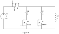
- Figure 4 shows an alternative OD circuit 200, with a resonant tank including an OD coil L1 and two parallel tuned capacitors C1 C2.
- C1 and C2 are chosen such that they resonate with L1 at two distinctively different frequencies (i.e. the FOD frequencies).
- M1 is opened and M2 closed, such that the frequency is defined by L1 (including reflected impedance) and C2.
- the frequency is again measured.
- the inductance in each case is then determined according to equation 2. If the change in inductance is over a threshold, then a FO has been identified
- the two frequencies can also be generated using the main IPT coil 7.
- the OD signals are superimposed by the inverter on top of the IPT power transfer signal.
- separate filters are provided in conjunction with a current transformer for each of the two OD frequencies.
- the filters may be notch filters or high/low pass filters, depending on the OD frequencies in relation to the IPT frequency.
- filters with fast roll off i.e. higher orders might be required.
Landscapes
- Engineering & Computer Science (AREA)
- Power Engineering (AREA)
- Computer Networks & Wireless Communication (AREA)
- Signal Processing (AREA)
- Geophysics And Detection Of Objects (AREA)
- Charge And Discharge Circuits For Batteries Or The Like (AREA)
- Near-Field Transmission Systems (AREA)
Claims (13)
- Induktiver Leistungssender (2), umfassend:einen Wandler (5), der konfiguriert ist, um mindestens zwei Objektdetektionssignale bei im Wesentlichen unterschiedlichen Frequenzen zu erzeugen, wobei eine erste der mindestens zwei Frequenzen signifikant niedriger als eine induktive Leistungsübertragungsfrequenz ist und eine zweite der mindestens zwei Frequenzen signifikant höher als eine induktive Leistungsübertragungsfrequenz ist,mindestens eine Sendespule (7), die konfiguriert ist, um ein Magnetfeld basierend auf den Objektdetektionssignalen zu erzeugen, undeine Steuerung (8), die konfiguriert ist, um einen oder mehrere Schaltungsparameter in Bezug auf die Spule (7) zu bestimmen oder zu messen, um eine Induktivität der Spule (7) bei jeder der Frequenzen zu bestimmen und abhängig von einer Änderung der Induktivität zwischen jeder der Frequenzen zu bestimmen, ob oder welche Art von Objekt vorhanden ist;wobei eine Bestimmung, ob ein Objekt vorhanden ist, darauf basiert, ob die Änderung der Induktivität unter oder über einem Schwellenwert liegt, und bestimmt wird, dass ein Fremdobjekt vorhanden ist, wenn die absolute Änderung der Induktivität über dem Schwellenwert liegt.
- Sender nach Anspruch 1, wobei die zwei Frequenzen ausgewählt werden, um vorbestimmte Fremdobjekte basierend auf der bekannten Skintiefe der vorbestimmten Fremdobjekte zu detektieren.
- Sender nach Anspruch 1 oder Anspruch 2, wobei die mindestens zwei Frequenzen mehr als 5 Mal verschieden sind oder wobei die mindestens zwei Frequenzen mehr als 10 Mal verschieden sind.
- Sender nach einem der vorhergehenden Ansprüche, wobei eine signifikante Abnahme der Induktivität zwischen jeder der Frequenzen ein metallisches Fremdobjekt anzeigt, wobei der Schwellenwert zum Detektieren metallischer Fremdobjekte zwischen 5-10 % liegt oder im Wesentlichen 10 % beträgt.
- Sender nach Anspruch 1, wobei die Spule mit einer induktiven Leistungssendespule gekoppelt ist und konfiguriert ist, um die mindestens zwei Objektdetektionssignale auf induktive Leistungsübertragungssignale zu überlagern, die durch den Sender erzeugt werden, so dass die Signale gleichzeitig arbeiten.
- Sender nach Anspruch 1, wobei die Spule eine induktive Leistungssendespule ist und konfiguriert ist, um die mindestens zwei Objektdetektionssignale auf das IPT-Signal zu überlagern, so dass die Signale gleichzeitig arbeiten.
- Sender nach Anspruch 1, wobei die Spule konfiguriert ist, um die mindestens zwei Objektdetektionssignale sequentiell mit induktiven Leistungsübertragungssignalen zu erzeugen.
- Sender nach einem der vorhergehenden Ansprüche, wobei die Steuerung ferner konfiguriert ist, um die induktive Leistungsübertragung zu einem induktiven Leistungsempfänger abhängig davon zu deaktivieren, ob ein Fremdobjekt vorhanden ist, und/oder wobei die Spule bei jeder der Frequenzen erregt wird und die Induktivität basierend auf der Spulenspannung und dem Spulenstrom bestimmt wird.
- Sender nach einem der vorhergehenden Ansprüche, wobei die Frequenz des induktiven Leistungsübertragungsfeldes zwischen 110 und 205 kHz liegt und/oder wobei die Frequenzen der Objektdetektionssignale zwischen 5 und 50 kHz und mehr als 500 kHz liegen.
- Sender nach einem der vorhergehenden Ansprüche, umfassend eine Vielzahl von drahtlosen Leistungsübertragungsspulen, wobei die Steuerung ferner konfiguriert ist, um eine erste Teilmenge der Vielzahl von drahtlosen Leistungsübertragungsspulen basierend auf einer Position des Objekts zu aktivieren.
- Sender nach einem der vorhergehenden Ansprüche, wobei der Wandler konfiguriert ist, um die Sendespule mit einer drahtlosen Leistungsübertragungsfrequenz anzutreiben, wobei eine obere Frequenz und eine untere Frequenz basierend auf der Art von Objekt ausgewählt werden, die für eine bestimmte Anwendung erwartet wird.
- Sender nach einem der vorhergehenden Ansprüche, wobei die Sendespule ferner konfiguriert ist, um ein drittes und viertes Objektdetektionssignal bei Frequenzen zu erzeugen, die sich von den mindestens zwei Frequenzen unterscheiden, die in den Ansprüchen 1-11 beschrieben sind, und
einen oder mehrere Schaltungsparameter in Bezug auf die Spule zu bestimmen oder zu messen, um die Induktivität der Spule bei jeder der dritten und vierten Frequenzen zu bestimmen und abhängig von einer Änderung der Induktivität zwischen jeder der Frequenzen zu bestimmen, welche Art von Objekt vorhanden ist. - Sender nach Anspruch 12, wobei die Frequenzen des dritten und vierten Objektdetektionssignals ausgewählt sind aus:einem ersten Frequenzbereich, der die erste Frequenz überspannt; undeinem zweiten Frequenzbereich, der die zweite Frequenz überspannt.
Applications Claiming Priority (3)
| Application Number | Priority Date | Filing Date | Title |
|---|---|---|---|
| US201562257659P | 2015-11-19 | 2015-11-19 | |
| PCT/NZ2016/050181 WO2017086804A1 (en) | 2015-11-19 | 2016-11-15 | Inductive power transmitter |
| EP16866726.9A EP3353875B1 (de) | 2015-11-19 | 2016-11-15 | Induktiver stromsender |
Related Parent Applications (2)
| Application Number | Title | Priority Date | Filing Date |
|---|---|---|---|
| EP16866726.9A Division EP3353875B1 (de) | 2015-11-19 | 2016-11-15 | Induktiver stromsender |
| EP16866726.9A Division-Into EP3353875B1 (de) | 2015-11-19 | 2016-11-15 | Induktiver stromsender |
Publications (2)
| Publication Number | Publication Date |
|---|---|
| EP3709470A1 EP3709470A1 (de) | 2020-09-16 |
| EP3709470B1 true EP3709470B1 (de) | 2024-11-13 |
Family
ID=58719084
Family Applications (2)
| Application Number | Title | Priority Date | Filing Date |
|---|---|---|---|
| EP16866726.9A Active EP3353875B1 (de) | 2015-11-19 | 2016-11-15 | Induktiver stromsender |
| EP20173240.1A Active EP3709470B1 (de) | 2015-11-19 | 2016-11-15 | Induktiver stromsender |
Family Applications Before (1)
| Application Number | Title | Priority Date | Filing Date |
|---|---|---|---|
| EP16866726.9A Active EP3353875B1 (de) | 2015-11-19 | 2016-11-15 | Induktiver stromsender |
Country Status (7)
| Country | Link |
|---|---|
| US (4) | US10923956B2 (de) |
| EP (2) | EP3353875B1 (de) |
| JP (1) | JP6600413B2 (de) |
| KR (2) | KR102242819B1 (de) |
| CN (2) | CN108401471B (de) |
| BR (1) | BR112018009532B1 (de) |
| WO (1) | WO2017086804A1 (de) |
Families Citing this family (19)
| Publication number | Priority date | Publication date | Assignee | Title |
|---|---|---|---|---|
| US10361565B2 (en) * | 2015-09-25 | 2019-07-23 | Intel Corporation | Detecting resonant frequencies |
| JP6600413B2 (ja) * | 2015-11-19 | 2019-10-30 | アップル インコーポレイテッド | 誘導電力送信機 |
| WO2017165432A1 (en) * | 2016-03-21 | 2017-09-28 | Google Incorporated | Modular lighting control system |
| KR20200045171A (ko) * | 2018-10-22 | 2020-05-04 | 엘지이노텍 주식회사 | 무선 전력 전송 방법 및 장치 |
| KR102630557B1 (ko) | 2018-11-16 | 2024-01-26 | 엘지전자 주식회사 | 무선전력 송신장치 |
| KR102532469B1 (ko) * | 2018-11-19 | 2023-05-12 | 엘지전자 주식회사 | 무선 전력 전송 장치 |
| CN109515220B (zh) * | 2018-12-16 | 2024-09-27 | 中国电建集团华东勘测设计研究院有限公司 | 一种应用于电动汽车双负载的无线充电装置及无线充电方法 |
| US11848572B2 (en) | 2019-07-26 | 2023-12-19 | Lg Electronics Inc. | Wireless power reception apparatus, wireless power transmission apparatus, and foreign matter detection method using same |
| JP7566483B2 (ja) * | 2020-03-31 | 2024-10-15 | キヤノン株式会社 | 送電装置、送電装置が行う方法およびプログラム |
| US12046922B2 (en) * | 2020-08-16 | 2024-07-23 | Aira, Inc. | Adaptive foreign object detection avoidance in a multi-coil wireless charging device |
| KR102850859B1 (ko) * | 2020-10-14 | 2025-08-26 | 엘지전자 주식회사 | 무선 전력을 송신하는 장치 및 방법 |
| US11942797B2 (en) | 2021-02-10 | 2024-03-26 | Nucurrent, Inc. | Virtual AC power signal transfer using wireless power transfer system |
| US11444492B2 (en) | 2021-02-10 | 2022-09-13 | Nucurrent, Inc. | Wireless power transfer systems for kitchen appliances |
| US11289952B1 (en) * | 2021-02-10 | 2022-03-29 | Nucurrent, Inc. | Slotted communications in virtual AC power signal transfer with variable slot width |
| FR3122785B1 (fr) * | 2021-05-04 | 2023-09-29 | Continental Automotive | Procede de detection d’un objet a charger et dispositif de charge associe |
| US12003119B2 (en) | 2021-05-12 | 2024-06-04 | Samsung Electronics Co., Ltd. | Electronic device and method for transmitting power based on multiple coils |
| US12074455B2 (en) * | 2021-07-21 | 2024-08-27 | Microchip Technology Incorporated | Object detection in wireless charging systems and related systems, methods, and devices |
| CN113472094B (zh) * | 2021-08-13 | 2024-07-26 | 上海伏达半导体有限公司 | 无线充电发射装置、谐振电路、品质因数的检测方法及处理器 |
| CN115384330A (zh) * | 2022-07-21 | 2022-11-25 | 广西电网有限责任公司电力科学研究院 | 一种双车位无线充电桩及其控制方法 |
Family Cites Families (132)
| Publication number | Priority date | Publication date | Assignee | Title |
|---|---|---|---|---|
| JPH01157896A (ja) | 1987-09-28 | 1989-06-21 | Mitsubishi Electric Corp | 非接触型icカード及び非接触型カードリーダライタ |
| ZA892468B (en) | 1988-04-11 | 1989-12-27 | Uniscan Ltd | Improvements in or relating to cutting elements foactuator and communication system r rotary drill bits |
| US5536979A (en) | 1994-06-30 | 1996-07-16 | Mceachern; Alexander | Charger for hand-held rechargeable electric apparatus with switch for reduced magnetic field |
| DE69714879T2 (de) | 1996-01-30 | 2003-05-08 | Sumitomo Wiring Systems, Ltd. | Verbindungssystem mit zugehörigem Verfahren |
| AU716214B2 (en) | 1996-05-03 | 2000-02-24 | Auckland Uniservices Limited | Inductively powered battery charger |
| FR2765736B1 (fr) | 1996-12-03 | 2000-04-28 | Jacques Patrick Andres | Systeme pour la fourniture d'energie electrique, notamment en exterieur et dans les lieux publics, borne et socle correspondants |
| US6061551A (en) | 1998-10-21 | 2000-05-09 | Parkervision, Inc. | Method and system for down-converting electromagnetic signals |
| JP3786392B2 (ja) | 1998-09-09 | 2006-06-14 | 本田技研工業株式会社 | 電動車両用充電装置 |
| DE19901983A1 (de) * | 1999-01-20 | 2000-08-10 | Perdix Oy Helsinki | Steuervorrichtung für einen induktiven Akkulader |
| US6803744B1 (en) | 1999-11-01 | 2004-10-12 | Anthony Sabo | Alignment independent and self aligning inductive power transfer system |
| EP1324278A1 (de) | 2001-12-28 | 2003-07-02 | Mars Incorporated | Kalibrierung von Geldechtheidsprüfern |
| US6710573B2 (en) | 2002-03-06 | 2004-03-23 | Andrew S. Kadah | Method of controlling pulsed AC power |
| GB2388715B (en) | 2002-05-13 | 2005-08-03 | Splashpower Ltd | Improvements relating to the transfer of electromagnetic power |
| US6844702B2 (en) | 2002-05-16 | 2005-01-18 | Koninklijke Philips Electronics N.V. | System, method and apparatus for contact-less battery charging with dynamic control |
| EP1547222B1 (de) | 2002-06-10 | 2018-10-03 | City University of Hong Kong | Planares induktives batterieladegerät |
| US7233137B2 (en) | 2003-09-30 | 2007-06-19 | Sharp Kabushiki Kaisha | Power supply system |
| US7605496B2 (en) | 2004-05-11 | 2009-10-20 | Access Business Group International Llc | Controlling inductive power transfer systems |
| GB2414120B (en) * | 2004-05-11 | 2008-04-02 | Splashpower Ltd | Controlling inductive power transfer systems |
| JP4188283B2 (ja) | 2004-06-07 | 2008-11-26 | アンリツ産機システム株式会社 | 金属検出機 |
| NZ535390A (en) | 2004-09-16 | 2007-10-26 | Auckland Uniservices Ltd | Inductively powered mobile sensor system |
| US7262700B2 (en) | 2005-03-10 | 2007-08-28 | Microsoft Corporation | Inductive powering surface for powering portable devices |
| CA2608663A1 (en) | 2005-05-18 | 2006-11-23 | Thermogear, Inc. | Heating system to alleviate hypothermia |
| US20070131505A1 (en) | 2005-07-16 | 2007-06-14 | Kim Bryan H J | Magnetic Induction Charging System for Vehicles |
| US7495414B2 (en) | 2005-07-25 | 2009-02-24 | Convenient Power Limited | Rechargeable battery circuit and structure for compatibility with a planar inductive charging platform |
| KR100792308B1 (ko) | 2006-01-31 | 2008-01-07 | 엘에스전선 주식회사 | 코일 어레이를 구비한 무접점 충전장치, 무접점 충전시스템 및 충전 방법 |
| US7952322B2 (en) | 2006-01-31 | 2011-05-31 | Mojo Mobility, Inc. | Inductive power source and charging system |
| US8169185B2 (en) | 2006-01-31 | 2012-05-01 | Mojo Mobility, Inc. | System and method for inductive charging of portable devices |
| EP1984193A2 (de) | 2006-02-13 | 2008-10-29 | Powercast Corporation | Implementierung eines hf-energiesenders und netzwerk |
| US7989986B2 (en) * | 2006-03-23 | 2011-08-02 | Access Business Group International Llc | Inductive power supply with device identification |
| EP2015588A4 (de) | 2006-04-26 | 2011-09-28 | Panasonic Corp | Videoverarbeitungseinrichtung, aufzeichnungsmedium, videosignalverarbeitungsverfahren, videosignalverarbeitungsprogramm und integrierte schaltung |
| WO2008026080A2 (en) | 2006-09-01 | 2008-03-06 | Bio Aim Technologies Holding Ltd. | Systems and methods for wireless power transfer |
| US20100314946A1 (en) | 2006-10-26 | 2010-12-16 | Koninklijke Philips Electronics N.V. | Floor covering and inductive power system |
| US20100328044A1 (en) | 2006-10-26 | 2010-12-30 | Koninklijke Philips Electronics N.V. | Inductive power system and method of operation |
| US7793121B2 (en) | 2007-03-01 | 2010-09-07 | Eastman Kodak Company | Charging display system |
| JP2008312294A (ja) | 2007-06-12 | 2008-12-25 | Ntt Docomo Inc | 充電器、被充電器、充電システム及び方法 |
| JP4525710B2 (ja) * | 2007-06-29 | 2010-08-18 | セイコーエプソン株式会社 | 送電制御装置、送電装置、電子機器及び無接点電力伝送システム |
| US20090001941A1 (en) | 2007-06-29 | 2009-01-01 | Microsoft Corporation | Inductive Powering Surface for Powering Portable Devices |
| ES2331393B1 (es) | 2007-07-11 | 2010-09-27 | Eric Van Looy | Procedimiento y dispositivo para la separacion de metales no ferrosos y acero inoxidable en manipulacion de materiales al por mayor. |
| JP2009027781A (ja) | 2007-07-17 | 2009-02-05 | Seiko Epson Corp | 受電制御装置、受電装置、無接点電力伝送システム、充電制御装置、バッテリ装置および電子機器 |
| JP2009038685A (ja) | 2007-08-02 | 2009-02-19 | Sony Corp | 画像信号出力装置及び画像信号出力方法 |
| GB0716679D0 (en) | 2007-08-28 | 2007-10-03 | Fells J | Inductive power supply |
| JP5072489B2 (ja) | 2007-08-30 | 2012-11-14 | 株式会社ジャパンディスプレイウェスト | 表示装置およびその駆動方法、電子機器 |
| CN101809842A (zh) | 2007-09-27 | 2010-08-18 | 松下电器产业株式会社 | 电子装置、充电器和充电装置 |
| JP5242111B2 (ja) | 2007-10-02 | 2013-07-24 | 株式会社ソニー・コンピュータエンタテインメント | 送信装置、画像データ送信方法、受信装置および受信装置における画像表示方法 |
| JP2009112137A (ja) | 2007-10-31 | 2009-05-21 | Meleagros Corp | 電力伝送装置の送電装置 |
| JP2009118587A (ja) | 2007-11-02 | 2009-05-28 | Meleagros Corp | 電力伝送装置 |
| CN103259344B (zh) | 2007-12-21 | 2016-08-10 | 捷通国际有限公司 | 用于感应功率传输的电路 |
| KR101061661B1 (ko) | 2008-01-09 | 2011-09-01 | 세이코 엡슨 가부시키가이샤 | 송전 제어 장치, 송전 장치, 무접점 전력 전송 시스템, 전자 기기 및 송전 제어 방법 |
| KR20100130215A (ko) | 2008-03-17 | 2010-12-10 | 파우워매트 엘티디. | 유도송전장치 |
| US9515494B2 (en) | 2008-09-27 | 2016-12-06 | Witricity Corporation | Wireless power system including impedance matching network |
| PL2347494T3 (pl) * | 2008-10-03 | 2019-08-30 | Philips Ip Ventures B.V. | System zasilający |
| JP2010118881A (ja) | 2008-11-13 | 2010-05-27 | Panasonic Corp | カラーマネージメントモジュール、カラーマネージメント装置、集積回路、表示装置 |
| JP5425539B2 (ja) | 2009-01-27 | 2014-02-26 | パナソニック株式会社 | 非接触電力伝送システム |
| JP5621203B2 (ja) | 2009-03-30 | 2014-11-12 | 富士通株式会社 | 無線電力供給システム、無線電力供給方法 |
| CA2757623A1 (en) | 2009-04-08 | 2010-10-14 | Access Business Group International Llc | Selectable coil array |
| DE202009009693U1 (de) | 2009-07-14 | 2010-11-25 | Conductix-Wampfler Ag | Vorrichtung zur induktiven Übertragung elektrischer Energie |
| DE102009033237A1 (de) | 2009-07-14 | 2011-01-20 | Conductix-Wampfler Ag | Vorrichtung zur induktiven Übertragung elektrischer Energie |
| US20110049997A1 (en) | 2009-09-03 | 2011-03-03 | Tdk Corporation | Wireless power feeder and wireless power transmission system |
| MX2010010556A (es) | 2009-09-24 | 2011-03-23 | R Byrne Norman | Transferencia de energia de superficie de trabajo. |
| US8575944B2 (en) * | 2009-11-03 | 2013-11-05 | Robert Bosch Gmbh | Foreign object detection in inductive coupled devices |
| JP2011114985A (ja) | 2009-11-27 | 2011-06-09 | Sanyo Electric Co Ltd | 電池内蔵機器と充電台 |
| TWI577103B (zh) | 2010-02-08 | 2017-04-01 | 通路實業集團國際公司 | 置入之寄生金屬檢測及其相關方法 |
| JP5051257B2 (ja) | 2010-03-16 | 2012-10-17 | トヨタ自動車株式会社 | 車両 |
| JP2011211760A (ja) | 2010-03-26 | 2011-10-20 | Panasonic Electric Works Co Ltd | 非接触給電装置及び非接触充電システム |
| US9294153B2 (en) | 2010-09-23 | 2016-03-22 | Texas Instruments Incorporated | Systems and methods of wireless power transfer with interference detection |
| US8587301B2 (en) | 2010-10-07 | 2013-11-19 | Mettler-Toledo Safeline Limited | Method for operating a metal detection system and metal detection system |
| JP5658592B2 (ja) | 2011-02-21 | 2015-01-28 | 国立大学法人埼玉大学 | 移動体用非接触給電装置 |
| JP6261978B2 (ja) * | 2011-03-31 | 2018-01-17 | ソニー株式会社 | 検知装置、送電装置、給電システムおよび検知方法 |
| JP5756925B2 (ja) * | 2011-05-19 | 2015-07-29 | パナソニックIpマネジメント株式会社 | 電気機器に設けられた受電装置 |
| KR20140039269A (ko) | 2011-06-10 | 2014-04-01 | 액세스 비지니스 그룹 인터내셔날 엘엘씨 | 유도 전력 수신기를 검출, 특성화, 및 추적하기 위한 시스템 및 방법 |
| DE102011105063B4 (de) | 2011-06-21 | 2023-09-21 | Airbus Operations Gmbh | Detektion eines Fremdkörpers in einem induktiven Übertragungsweg |
| JP2013027074A (ja) | 2011-07-15 | 2013-02-04 | Panasonic Corp | 非接触給電装置 |
| JP6035711B2 (ja) * | 2011-07-21 | 2016-11-30 | ソニー株式会社 | 検知装置、受電装置、送電装置、非接触電力伝送システム及び検知方法 |
| US8823318B2 (en) | 2011-07-25 | 2014-09-02 | ConvenientPower HK Ltd. | System and method for operating a mobile device |
| JP5838333B2 (ja) | 2011-08-01 | 2016-01-06 | パナソニックIpマネジメント株式会社 | 非接触給電装置 |
| JP5857251B2 (ja) | 2011-08-01 | 2016-02-10 | パナソニックIpマネジメント株式会社 | 非接触給電装置の制御方法及び非接触給電装置 |
| JP5853199B2 (ja) | 2011-08-25 | 2016-02-09 | パナソニックIpマネジメント株式会社 | 非接触給電システムの金属異物検出方法、非接触給電装置、電気機器に設けられた受電装置及び非接触給電システム |
| JP6185472B2 (ja) | 2011-09-09 | 2017-08-23 | ワイトリシティ コーポレーションWitricity Corporation | ワイヤレスエネルギー伝送システムにおける異物検出 |
| US9252846B2 (en) | 2011-09-09 | 2016-02-02 | Qualcomm Incorporated | Systems and methods for detecting and identifying a wireless power device |
| JP5794056B2 (ja) | 2011-09-12 | 2015-10-14 | ソニー株式会社 | 給電装置および給電システム |
| US9553485B2 (en) * | 2011-10-13 | 2017-01-24 | Integrated Device Technology, Inc. | Apparatus, system, and method for detecting a foreign object in an inductive wireless power transfer system based on input power |
| US20130097078A1 (en) | 2011-10-17 | 2013-04-18 | Shoon Ping Wong | Mobile remote payment system |
| US9118203B2 (en) | 2011-11-15 | 2015-08-25 | Qualcomm Incorporated | Systems and methods for induction charging with a closed magnetic loop |
| JP2013115978A (ja) | 2011-11-30 | 2013-06-10 | Sanyo Electric Co Ltd | 携帯機器及び給電台と携帯機器の給電方法 |
| JP5838768B2 (ja) | 2011-11-30 | 2016-01-06 | ソニー株式会社 | 検知装置、受電装置、非接触電力伝送システム及び検知方法 |
| KR101951358B1 (ko) | 2011-12-15 | 2019-02-22 | 삼성전자주식회사 | 무선 전력 송신기 및 그 제어 방법 |
| CN104380567A (zh) | 2012-02-16 | 2015-02-25 | 奥克兰联合服务有限公司 | 多线圈通量衬垫 |
| KR20130099699A (ko) | 2012-02-29 | 2013-09-06 | 주식회사 팬택 | 무접점 충전 장치, 피충전 단말기 및 무접점 충전 방법 |
| JP2013192391A (ja) | 2012-03-14 | 2013-09-26 | Sony Corp | 検知装置、受電装置、送電装置及び非接触給電システム |
| JP5884610B2 (ja) * | 2012-04-10 | 2016-03-15 | ソニー株式会社 | 受電装置、受電装置の制御方法、および、給電システム |
| WO2013164831A1 (en) * | 2012-05-03 | 2013-11-07 | Powermat Technologies Ltd. | System and method for triggering power transfer across an inductive power coupling and non resonant transmission |
| JP5948676B2 (ja) | 2012-05-18 | 2016-07-06 | パナソニックIpマネジメント株式会社 | 非接触給電システム、非接触給電装置、及び被給電装置 |
| US10084350B2 (en) * | 2012-05-29 | 2018-09-25 | Pioneer Corporation | Wireless power transmission system and method |
| US20150178532A1 (en) | 2012-06-20 | 2015-06-25 | David Allen Brulé | Wearable rfid storage devices |
| GB2503254B (en) | 2012-06-20 | 2014-12-17 | Dyson Technology Ltd | A cleaning appliance |
| KR101912692B1 (ko) | 2012-07-06 | 2018-10-29 | 엘지전자 주식회사 | 무선 전력 전송에서의 주파수를 주기적으로 변경하는 방법 및 장치 |
| CN103529297A (zh) | 2012-07-06 | 2014-01-22 | 鸿富锦精密工业(深圳)有限公司 | 阻抗测试装置 |
| KR101950688B1 (ko) * | 2012-07-09 | 2019-02-21 | 삼성전자주식회사 | 무선 전력 송신기 및 그 제어 방법 |
| KR101962667B1 (ko) * | 2012-07-12 | 2019-03-27 | 삼성전자주식회사 | 무선 전력 송신기, 무선 전력 수신기 및 각각의 제어 방법 |
| US9726518B2 (en) * | 2012-07-13 | 2017-08-08 | Qualcomm Incorporated | Systems, methods, and apparatus for detection of metal objects in a predetermined space |
| JP6079026B2 (ja) | 2012-07-26 | 2017-02-15 | Tdk株式会社 | コイルユニットおよびそれを用いたワイヤレス給電装置 |
| US9178361B2 (en) * | 2012-09-27 | 2015-11-03 | ConvenientPower, Ltd. | Methods and systems for detecting foreign objects in a wireless charging system |
| US9190876B2 (en) | 2012-09-28 | 2015-11-17 | Qualcomm Incorporated | Systems and methods for detecting wireless charging transmit characteristics |
| US9236757B2 (en) | 2012-09-28 | 2016-01-12 | Broadcom Corporation | Wireless power transfer adaptation triggers |
| TW201415749A (zh) | 2012-10-12 | 2014-04-16 | Espower Electronics Inc | 多機型無線電源供應系統 |
| EP2909917B1 (de) | 2012-10-16 | 2020-11-11 | Koninklijke Philips N.V. | Drahtlose induktive energieübertragung |
| WO2014063159A2 (en) | 2012-10-19 | 2014-04-24 | Witricity Corporation | Foreign object detection in wireless energy transfer systems |
| CN104798315B (zh) | 2012-11-29 | 2017-06-20 | 皇家飞利浦有限公司 | 无线感应式电力传输 |
| GB2508923A (en) | 2012-12-17 | 2014-06-18 | Bombardier Transp Gmbh | Inductive power transfer system having inductive sensing array |
| JP5910490B2 (ja) | 2012-12-27 | 2016-04-27 | 株式会社デンソー | 金属物体検知装置 |
| EP2961037B1 (de) * | 2013-02-19 | 2017-06-28 | Panasonic Intellectual Property Management Co., Ltd. | Vorrichtung zur fremdobjekterkennung, verfahren zur fremdobjekterkennung und kontaktloses ladesystem |
| JP6026354B2 (ja) * | 2013-05-14 | 2016-11-16 | 東光株式会社 | ワイヤレス電力伝送装置 |
| JP6152310B2 (ja) | 2013-06-28 | 2017-06-21 | 理想科学工業株式会社 | 画像形成装置 |
| JP6122716B2 (ja) | 2013-07-11 | 2017-04-26 | 株式会社東芝 | 画像処理装置 |
| US20150229932A1 (en) | 2013-07-12 | 2015-08-13 | Sony Corporation | Image processing device and image processing method |
| WO2015021144A1 (en) * | 2013-08-06 | 2015-02-12 | Momentum Dynamics Corporation | A method of and apparatue for detecting coil alignment error in wirelss inductive power transmission |
| JP6387222B2 (ja) * | 2013-08-28 | 2018-09-05 | ソニー株式会社 | 給電装置、受電装置、給電システム、および、給電装置の制御方法 |
| US20150070094A1 (en) | 2013-09-10 | 2015-03-12 | Telefonaktiebolaget Lm Ericsson (Publ) | Doherty power amplifier with coupling mechanism independent of device ratios |
| JP2015095905A (ja) * | 2013-11-08 | 2015-05-18 | 三洋電機株式会社 | 無接点電力搬送方法 |
| US9878309B2 (en) | 2013-12-06 | 2018-01-30 | Danmarks Tekniske Universitet | Catalyst for ammonia oxidation |
| JP6315382B2 (ja) * | 2013-12-19 | 2018-04-25 | パナソニックIpマネジメント株式会社 | 無線電力伝送のための送電装置および受電装置ならびに無線電力伝送システム |
| WO2015108326A1 (en) | 2014-01-14 | 2015-07-23 | Lg Electronics Inc. | Apparatus for transmitting broadcast signals, apparatus for receiving broadcast signals, method for transmitting broadcast signals and method for receiving broadcast signals |
| WO2015119458A1 (en) | 2014-02-07 | 2015-08-13 | Lg Electronics Inc. | Wireless power transfer and receive method, apparatus and system |
| KR101792140B1 (ko) | 2014-02-07 | 2017-11-02 | 엘지전자 주식회사 | 무선 전력 전송방법, 무선 전력 전송장치, 무선 전력 수신장치 및 무선 충전 시스템 |
| US9939539B2 (en) | 2014-04-04 | 2018-04-10 | Texas Instruments Incorporated | Wireless power receiver and/or foreign object detection by a wireless power transmitter |
| WO2015171910A1 (en) * | 2014-05-07 | 2015-11-12 | Witricity Corporation | Foreign object detection in wireless energy transfer systems |
| US10601251B2 (en) | 2014-08-12 | 2020-03-24 | Apple Inc. | System and method for power transfer |
| EP3212528A1 (de) | 2014-10-31 | 2017-09-06 | Polyone Designed Structures and Solutions LLC | Verschachtelte verpackungsanordnungen |
| US9379841B2 (en) | 2014-11-17 | 2016-06-28 | Empire Technology Development Llc | Mobile device prevention of contactless card attacks |
| CN112564299B (zh) | 2015-03-04 | 2024-03-05 | 苹果公司 | 感应功率发射器 |
| JP6600413B2 (ja) * | 2015-11-19 | 2019-10-30 | アップル インコーポレイテッド | 誘導電力送信機 |
| US10804748B2 (en) * | 2016-12-14 | 2020-10-13 | Apple Inc. | Wireless power system with foreign object detection |
-
2016
- 2016-11-15 JP JP2018525471A patent/JP6600413B2/ja active Active
- 2016-11-15 KR KR1020207018430A patent/KR102242819B1/ko active Active
- 2016-11-15 KR KR1020187013030A patent/KR102130791B1/ko active Active
- 2016-11-15 EP EP16866726.9A patent/EP3353875B1/de active Active
- 2016-11-15 BR BR112018009532-0A patent/BR112018009532B1/pt active IP Right Grant
- 2016-11-15 WO PCT/NZ2016/050181 patent/WO2017086804A1/en not_active Ceased
- 2016-11-15 EP EP20173240.1A patent/EP3709470B1/de active Active
- 2016-11-15 CN CN201680067411.XA patent/CN108401471B/zh active Active
- 2016-11-15 CN CN202110652035.3A patent/CN113364064A/zh active Pending
-
2018
- 2018-04-30 US US15/966,511 patent/US10923956B2/en active Active
-
2019
- 2019-08-27 US US16/552,179 patent/US20190386519A1/en not_active Abandoned
-
2021
- 2021-01-14 US US17/149,167 patent/US11791659B2/en active Active
-
2023
- 2023-09-12 US US18/465,493 patent/US20240006924A1/en not_active Abandoned
Also Published As
| Publication number | Publication date |
|---|---|
| EP3353875A4 (de) | 2019-05-15 |
| CN108401471A (zh) | 2018-08-14 |
| CN108401471B (zh) | 2021-06-25 |
| KR102130791B1 (ko) | 2020-07-06 |
| CN113364064A (zh) | 2021-09-07 |
| US11791659B2 (en) | 2023-10-17 |
| WO2017086804A1 (en) | 2017-05-26 |
| US20180248408A1 (en) | 2018-08-30 |
| US20240006924A1 (en) | 2024-01-04 |
| US10923956B2 (en) | 2021-02-16 |
| KR20200083633A (ko) | 2020-07-08 |
| BR112018009532B1 (pt) | 2022-11-01 |
| KR102242819B1 (ko) | 2021-04-22 |
| JP2018533905A (ja) | 2018-11-15 |
| BR112018009532A2 (pt) | 2018-11-06 |
| EP3709470A1 (de) | 2020-09-16 |
| EP3353875A1 (de) | 2018-08-01 |
| US20210135499A1 (en) | 2021-05-06 |
| EP3353875B1 (de) | 2020-06-24 |
| JP6600413B2 (ja) | 2019-10-30 |
| KR20180066176A (ko) | 2018-06-18 |
| US20190386519A1 (en) | 2019-12-19 |
Similar Documents
| Publication | Publication Date | Title |
|---|---|---|
| EP3709470B1 (de) | Induktiver stromsender | |
| EP3278421B1 (de) | Induktiver stromsender | |
| US12296698B2 (en) | Device, system and method for detection of a foreign object | |
| CN110474446B (zh) | 供电设备、受电设备、供电系统及控制供电的方法 | |
| US20170317536A1 (en) | Inductive power transmitter | |
| US20170179772A1 (en) | Foreign object detector, power transmitting device and power receiving device for wireless power transmission, and wireless power transmission system |
Legal Events
| Date | Code | Title | Description |
|---|---|---|---|
| PUAI | Public reference made under article 153(3) epc to a published international application that has entered the european phase |
Free format text: ORIGINAL CODE: 0009012 |
|
| STAA | Information on the status of an ep patent application or granted ep patent |
Free format text: STATUS: REQUEST FOR EXAMINATION WAS MADE |
|
| 17P | Request for examination filed |
Effective date: 20200506 |
|
| AC | Divisional application: reference to earlier application |
Ref document number: 3353875 Country of ref document: EP Kind code of ref document: P |
|
| AK | Designated contracting states |
Kind code of ref document: A1 Designated state(s): AL AT BE BG CH CY CZ DE DK EE ES FI FR GB GR HR HU IE IS IT LI LT LU LV MC MK MT NL NO PL PT RO RS SE SI SK SM TR |
|
| STAA | Information on the status of an ep patent application or granted ep patent |
Free format text: STATUS: EXAMINATION IS IN PROGRESS |
|
| 17Q | First examination report despatched |
Effective date: 20220701 |
|
| GRAP | Despatch of communication of intention to grant a patent |
Free format text: ORIGINAL CODE: EPIDOSNIGR1 |
|
| STAA | Information on the status of an ep patent application or granted ep patent |
Free format text: STATUS: GRANT OF PATENT IS INTENDED |
|
| INTG | Intention to grant announced |
Effective date: 20240610 |
|
| GRAS | Grant fee paid |
Free format text: ORIGINAL CODE: EPIDOSNIGR3 |
|
| GRAA | (expected) grant |
Free format text: ORIGINAL CODE: 0009210 |
|
| STAA | Information on the status of an ep patent application or granted ep patent |
Free format text: STATUS: THE PATENT HAS BEEN GRANTED |
|
| AC | Divisional application: reference to earlier application |
Ref document number: 3353875 Country of ref document: EP Kind code of ref document: P |
|
| AK | Designated contracting states |
Kind code of ref document: B1 Designated state(s): AL AT BE BG CH CY CZ DE DK EE ES FI FR GB GR HR HU IE IS IT LI LT LU LV MC MK MT NL NO PL PT RO RS SE SI SK SM TR |
|
| REG | Reference to a national code |
Ref country code: GB Ref legal event code: FG4D |
|
| REG | Reference to a national code |
Ref country code: CH Ref legal event code: EP |
|
| REG | Reference to a national code |
Ref country code: DE Ref legal event code: R096 Ref document number: 602016090270 Country of ref document: DE |
|
| REG | Reference to a national code |
Ref country code: IE Ref legal event code: FG4D |
|
| REG | Reference to a national code |
Ref country code: LT Ref legal event code: MG9D |
|
| REG | Reference to a national code |
Ref country code: NL Ref legal event code: MP Effective date: 20241113 |
|
| PG25 | Lapsed in a contracting state [announced via postgrant information from national office to epo] |
Ref country code: PT Free format text: LAPSE BECAUSE OF FAILURE TO SUBMIT A TRANSLATION OF THE DESCRIPTION OR TO PAY THE FEE WITHIN THE PRESCRIBED TIME-LIMIT Effective date: 20250313 Ref country code: IS Free format text: LAPSE BECAUSE OF FAILURE TO SUBMIT A TRANSLATION OF THE DESCRIPTION OR TO PAY THE FEE WITHIN THE PRESCRIBED TIME-LIMIT Effective date: 20250313 Ref country code: HR Free format text: LAPSE BECAUSE OF FAILURE TO SUBMIT A TRANSLATION OF THE DESCRIPTION OR TO PAY THE FEE WITHIN THE PRESCRIBED TIME-LIMIT Effective date: 20241113 |
|
| PG25 | Lapsed in a contracting state [announced via postgrant information from national office to epo] |
Ref country code: NL Free format text: LAPSE BECAUSE OF FAILURE TO SUBMIT A TRANSLATION OF THE DESCRIPTION OR TO PAY THE FEE WITHIN THE PRESCRIBED TIME-LIMIT Effective date: 20241113 Ref country code: FI Free format text: LAPSE BECAUSE OF FAILURE TO SUBMIT A TRANSLATION OF THE DESCRIPTION OR TO PAY THE FEE WITHIN THE PRESCRIBED TIME-LIMIT Effective date: 20241113 |
|
| REG | Reference to a national code |
Ref country code: AT Ref legal event code: MK05 Ref document number: 1742422 Country of ref document: AT Kind code of ref document: T Effective date: 20241113 |
|
| PG25 | Lapsed in a contracting state [announced via postgrant information from national office to epo] |
Ref country code: BG Free format text: LAPSE BECAUSE OF FAILURE TO SUBMIT A TRANSLATION OF THE DESCRIPTION OR TO PAY THE FEE WITHIN THE PRESCRIBED TIME-LIMIT Effective date: 20241113 |
|
| PG25 | Lapsed in a contracting state [announced via postgrant information from national office to epo] |
Ref country code: ES Free format text: LAPSE BECAUSE OF FAILURE TO SUBMIT A TRANSLATION OF THE DESCRIPTION OR TO PAY THE FEE WITHIN THE PRESCRIBED TIME-LIMIT Effective date: 20241113 |
|
| PG25 | Lapsed in a contracting state [announced via postgrant information from national office to epo] |
Ref country code: NO Free format text: LAPSE BECAUSE OF FAILURE TO SUBMIT A TRANSLATION OF THE DESCRIPTION OR TO PAY THE FEE WITHIN THE PRESCRIBED TIME-LIMIT Effective date: 20250213 |
|
| PG25 | Lapsed in a contracting state [announced via postgrant information from national office to epo] |
Ref country code: AT Free format text: LAPSE BECAUSE OF FAILURE TO SUBMIT A TRANSLATION OF THE DESCRIPTION OR TO PAY THE FEE WITHIN THE PRESCRIBED TIME-LIMIT Effective date: 20241113 Ref country code: GR Free format text: LAPSE BECAUSE OF FAILURE TO SUBMIT A TRANSLATION OF THE DESCRIPTION OR TO PAY THE FEE WITHIN THE PRESCRIBED TIME-LIMIT Effective date: 20250214 Ref country code: LV Free format text: LAPSE BECAUSE OF FAILURE TO SUBMIT A TRANSLATION OF THE DESCRIPTION OR TO PAY THE FEE WITHIN THE PRESCRIBED TIME-LIMIT Effective date: 20241113 |
|
| PG25 | Lapsed in a contracting state [announced via postgrant information from national office to epo] |
Ref country code: PL Free format text: LAPSE BECAUSE OF FAILURE TO SUBMIT A TRANSLATION OF THE DESCRIPTION OR TO PAY THE FEE WITHIN THE PRESCRIBED TIME-LIMIT Effective date: 20241113 |
|
| PG25 | Lapsed in a contracting state [announced via postgrant information from national office to epo] |
Ref country code: RS Free format text: LAPSE BECAUSE OF FAILURE TO SUBMIT A TRANSLATION OF THE DESCRIPTION OR TO PAY THE FEE WITHIN THE PRESCRIBED TIME-LIMIT Effective date: 20250213 |
|
| REG | Reference to a national code |
Ref country code: CH Ref legal event code: PL |
|
| PG25 | Lapsed in a contracting state [announced via postgrant information from national office to epo] |
Ref country code: SM Free format text: LAPSE BECAUSE OF FAILURE TO SUBMIT A TRANSLATION OF THE DESCRIPTION OR TO PAY THE FEE WITHIN THE PRESCRIBED TIME-LIMIT Effective date: 20241113 |
|
| PG25 | Lapsed in a contracting state [announced via postgrant information from national office to epo] |
Ref country code: DK Free format text: LAPSE BECAUSE OF FAILURE TO SUBMIT A TRANSLATION OF THE DESCRIPTION OR TO PAY THE FEE WITHIN THE PRESCRIBED TIME-LIMIT Effective date: 20241113 |
|
| PG25 | Lapsed in a contracting state [announced via postgrant information from national office to epo] |
Ref country code: LU Free format text: LAPSE BECAUSE OF NON-PAYMENT OF DUE FEES Effective date: 20241115 |
|
| REG | Reference to a national code |
Ref country code: CH Ref legal event code: PL |
|
| PG25 | Lapsed in a contracting state [announced via postgrant information from national office to epo] |
Ref country code: EE Free format text: LAPSE BECAUSE OF FAILURE TO SUBMIT A TRANSLATION OF THE DESCRIPTION OR TO PAY THE FEE WITHIN THE PRESCRIBED TIME-LIMIT Effective date: 20241113 |
|
| PG25 | Lapsed in a contracting state [announced via postgrant information from national office to epo] |
Ref country code: CH Free format text: LAPSE BECAUSE OF NON-PAYMENT OF DUE FEES Effective date: 20241130 |
|
| PG25 | Lapsed in a contracting state [announced via postgrant information from national office to epo] |
Ref country code: RO Free format text: LAPSE BECAUSE OF FAILURE TO SUBMIT A TRANSLATION OF THE DESCRIPTION OR TO PAY THE FEE WITHIN THE PRESCRIBED TIME-LIMIT Effective date: 20241113 |
|
| PG25 | Lapsed in a contracting state [announced via postgrant information from national office to epo] |
Ref country code: SK Free format text: LAPSE BECAUSE OF FAILURE TO SUBMIT A TRANSLATION OF THE DESCRIPTION OR TO PAY THE FEE WITHIN THE PRESCRIBED TIME-LIMIT Effective date: 20241113 |
|
| PG25 | Lapsed in a contracting state [announced via postgrant information from national office to epo] |
Ref country code: CZ Free format text: LAPSE BECAUSE OF FAILURE TO SUBMIT A TRANSLATION OF THE DESCRIPTION OR TO PAY THE FEE WITHIN THE PRESCRIBED TIME-LIMIT Effective date: 20241113 |
|
| PG25 | Lapsed in a contracting state [announced via postgrant information from national office to epo] |
Ref country code: IT Free format text: LAPSE BECAUSE OF FAILURE TO SUBMIT A TRANSLATION OF THE DESCRIPTION OR TO PAY THE FEE WITHIN THE PRESCRIBED TIME-LIMIT Effective date: 20241113 |
|
| REG | Reference to a national code |
Ref country code: DE Ref legal event code: R097 Ref document number: 602016090270 Country of ref document: DE |
|
| REG | Reference to a national code |
Ref country code: BE Ref legal event code: MM Effective date: 20241130 |
|
| PG25 | Lapsed in a contracting state [announced via postgrant information from national office to epo] |
Ref country code: SE Free format text: LAPSE BECAUSE OF FAILURE TO SUBMIT A TRANSLATION OF THE DESCRIPTION OR TO PAY THE FEE WITHIN THE PRESCRIBED TIME-LIMIT Effective date: 20241113 |
|
| PG25 | Lapsed in a contracting state [announced via postgrant information from national office to epo] |
Ref country code: MC Free format text: LAPSE BECAUSE OF FAILURE TO SUBMIT A TRANSLATION OF THE DESCRIPTION OR TO PAY THE FEE WITHIN THE PRESCRIBED TIME-LIMIT Effective date: 20241113 |
|
| PLBE | No opposition filed within time limit |
Free format text: ORIGINAL CODE: 0009261 |
|
| STAA | Information on the status of an ep patent application or granted ep patent |
Free format text: STATUS: NO OPPOSITION FILED WITHIN TIME LIMIT |
|
| PG25 | Lapsed in a contracting state [announced via postgrant information from national office to epo] |
Ref country code: BE Free format text: LAPSE BECAUSE OF NON-PAYMENT OF DUE FEES Effective date: 20241130 |
|
| PGFP | Annual fee paid to national office [announced via postgrant information from national office to epo] |
Ref country code: GB Payment date: 20250925 Year of fee payment: 10 |
|
| PG25 | Lapsed in a contracting state [announced via postgrant information from national office to epo] |
Ref country code: FR Free format text: LAPSE BECAUSE OF NON-PAYMENT OF DUE FEES Effective date: 20250113 |
|
| 26N | No opposition filed |
Effective date: 20250814 |
|
| PG25 | Lapsed in a contracting state [announced via postgrant information from national office to epo] |
Ref country code: IE Free format text: LAPSE BECAUSE OF NON-PAYMENT OF DUE FEES Effective date: 20241115 |
|
| REG | Reference to a national code |
Ref country code: DE Ref legal event code: R079 Ref document number: 602016090270 Country of ref document: DE Free format text: PREVIOUS MAIN CLASS: H02J0005000000 Ipc: H02J0004250000 |
|
| PGFP | Annual fee paid to national office [announced via postgrant information from national office to epo] |
Ref country code: DE Payment date: 20250923 Year of fee payment: 10 |
|
| PG25 | Lapsed in a contracting state [announced via postgrant information from national office to epo] |
Ref country code: HU Free format text: LAPSE BECAUSE OF FAILURE TO SUBMIT A TRANSLATION OF THE DESCRIPTION OR TO PAY THE FEE WITHIN THE PRESCRIBED TIME-LIMIT; INVALID AB INITIO Effective date: 20161115 |
|
| PG25 | Lapsed in a contracting state [announced via postgrant information from national office to epo] |
Ref country code: CY Free format text: LAPSE BECAUSE OF FAILURE TO SUBMIT A TRANSLATION OF THE DESCRIPTION OR TO PAY THE FEE WITHIN THE PRESCRIBED TIME-LIMIT; INVALID AB INITIO Effective date: 20161115 |