EP3708725B1 - Siphoneinrichtung - Google Patents
Siphoneinrichtung Download PDFInfo
- Publication number
- EP3708725B1 EP3708725B1 EP19216941.5A EP19216941A EP3708725B1 EP 3708725 B1 EP3708725 B1 EP 3708725B1 EP 19216941 A EP19216941 A EP 19216941A EP 3708725 B1 EP3708725 B1 EP 3708725B1
- Authority
- EP
- European Patent Office
- Prior art keywords
- siphon device
- deflection
- flow channel
- cross
- connecting part
- Prior art date
- Legal status (The legal status is an assumption and is not a legal conclusion. Google has not performed a legal analysis and makes no representation as to the accuracy of the status listed.)
- Active
Links
Images

Classifications
-
- E—FIXED CONSTRUCTIONS
- E03—WATER SUPPLY; SEWERAGE
- E03C—DOMESTIC PLUMBING INSTALLATIONS FOR FRESH WATER OR WASTE WATER; SINKS
- E03C1/00—Domestic plumbing installations for fresh water or waste water; Sinks
- E03C1/12—Plumbing installations for waste water; Basins or fountains connected thereto; Sinks
- E03C1/28—Odour seals
- E03C1/284—Odour seals having U-shaped trap
-
- E—FIXED CONSTRUCTIONS
- E03—WATER SUPPLY; SEWERAGE
- E03C—DOMESTIC PLUMBING INSTALLATIONS FOR FRESH WATER OR WASTE WATER; SINKS
- E03C1/00—Domestic plumbing installations for fresh water or waste water; Sinks
- E03C1/12—Plumbing installations for waste water; Basins or fountains connected thereto; Sinks
- E03C1/28—Odour seals
- E03C1/29—Odour seals having housing containing dividing wall, e.g. tubular
-
- E—FIXED CONSTRUCTIONS
- E03—WATER SUPPLY; SEWERAGE
- E03F—SEWERS; CESSPOOLS
- E03F5/00—Sewerage structures
- E03F5/04—Gullies inlets, road sinks, floor drains with or without odour seals or sediment traps
- E03F5/0407—Floor drains for indoor use
- E03F5/0408—Floor drains for indoor use specially adapted for showers
-
- E—FIXED CONSTRUCTIONS
- E03—WATER SUPPLY; SEWERAGE
- E03F—SEWERS; CESSPOOLS
- E03F5/00—Sewerage structures
- E03F5/04—Gullies inlets, road sinks, floor drains with or without odour seals or sediment traps
- E03F2005/0416—Gullies inlets, road sinks, floor drains with or without odour seals or sediment traps with an odour seal
- E03F2005/0418—Gullies inlets, road sinks, floor drains with or without odour seals or sediment traps with an odour seal in the form of a bell siphon
Definitions
- the invention relates to a siphon device, in particular for a wash basin in the sanitary area, with a tubular connecting part which can be connected to the wash basin and a deflecting part connected to the connecting part, by means of which a liquid flowing through the siphon device can be collected in order to form an odor trap.
- Such a siphon device comprises several interconnected pipes with a circular cross-section.
- a connecting pipe arranged approximately vertically, is connected to a washing area and usually extends downwards more than 20 cm from the washing area. This is followed by a first bend for diverting a liquid flowing through the siphon device by approximately 180° upwards towards the washing area and a second bend for diverting the liquid by approximately 90° towards a wall.
- an overflow device for the washing area and a lifting rod for a valve device for accumulating the liquid in the washing area are also connected to the siphon device. This can lead to the spread of unpleasant odors. While strong cleaning agents can mask unpleasant odors, the often difficult-to-access source of bacteria often remains.
- siphon devices become dirty relatively quickly because dirt often gets stuck and remains in the siphon device. Cleaning the siphon device up to the level of the sealing liquid in the siphon is possible without dismantling the entire Due to their design and dimensions, drawers below the washbasin, such as a vanity unit, require a drawer cutout, which usually significantly reduces the drawer's storage space.
- Other siphon devices are available, for example, from DE 201 00 826 U1 , DE 20 2014 007392 U1 and DE 10 2009 043 859 A1 known.
- the invention is based on the object of creating a siphon device that is easier to handle.
- the siphon device has a tubular connecting piece that can be connected to the wash basin and a diverting piece connected to the connecting piece.
- the diverting piece allows liquid flowing through the siphon device to be collected to form an odor trap.
- the connecting piece and diverting piece are designed such that the flow velocity in the diverting piece is higher than that in the connecting piece.
- a higher flow velocity in the diverting piece promotes self-cleaning effects, so that dirt particles are less likely to accumulate on the inner walls of the siphon device. By increasing the flow velocity, dirt particles located in the connecting piece are more easily sucked in and transported away by the diverting piece.
- the ratio of the flow cross-section of the connecting part to the flow cross-section of the deflection part is between 5:1 and 1.5:1, preferably between 4:1 and 2:1, particularly preferably 3:1.
- a reduction in cross-section therefore simply leads to an increase in the velocity of the liquid flowing through the siphon device in the area of the deflection part, so that dirt particles are less likely to deposit on the interior walls.
- the siphon device according to the invention is easier to handle.
- the aforementioned ratios of the flow cross-sections to one another also promote the throughput required in practice by modern siphon devices. This further development is based on the finding that self-cleaning of pipelines is achieved in a siphon device, particularly when a flow velocity of approximately 0.7 m/s is present periodically.
- the previously described increase in flow velocity can be achieved particularly easily by having the connecting part with a circular flow cross-section and the deflecting part with a flow channel with a cross-sectional area in the shape of an elongated hole, whereby the diameter of the circular cross-sectional area of the connecting part corresponds to the length of the elongated hole of the flow channel.
- This largely eliminates protrusions, recesses, edges, or gussets in the flow cross-section, all of which promote the accumulation of dirt. Dirt particles are therefore less likely to become trapped and remain; moreover, cleaning is easier due to the continuous transitions.
- the deflection part opens into the connecting part at an angle of approximately 90°. Due to the 90° deflection in the area between the connecting part and the deflection part, the flow velocity at the edge is usually increased, which can promote the removal of dirt particles and largely prevent them from accumulating on the inner wall. The aforementioned abrupt change in flow direction can also help reduce the accumulation of dirt in parts of the siphon device.
- the flow channel of the deflection part has, in the region of its junction with the connecting part, a rounded upper side which merges into the flow cross-section of the connecting part, wherein
- the radius of the rounded upper surface of the flow channel of the deflection part corresponds to that of another deflection in the flow channel of the deflection part.
- the rounded upper surface allows the flow cross-section for the fluid flowing from the connecting part into the deflection part to be largely continuously reduced. This can promote the occurrence of suction effects.
- the radius of each inner curve of the flow channel of the deflection part corresponds approximately to the height of the flow channel of the deflection part
- the radius of each outer curve of the flow channel of the deflection part corresponds approximately to twice the height of the flow channel of the deflection part, as will be explained below.
- the deflection part has a drain pipe at its end opposite the connecting part with a diameter that approximately corresponds to the length of the elongated hole in the flow channel of the deflection part.
- This refinement can also contribute to a laminar fluid flow through the siphon device and thus to high drainage performance.
- the longitudinal axes of the drain pipe and the deflection part form an angle of approximately 120°, and the drain pipe, with its entire cross-sectional area below the further deflection, opens into the flow channel of the deflection part.
- the cross-sectional expansion occurs exclusively in height. This means that the connecting pipe remains ventilated, so that no suction effect, for example, on the Sealing fluid can form in the siphon device if additional flushing is activated in a downpipe connected to the drain pipe.
- the area at the upper curve of the tubular flow cross-section in the drain pipe is ventilated, largely preventing the formation of an air cushion.
- the siphon device has a total height of approximately 80 mm with a barrier fluid height of approximately 50 mm.
- This embodiment contributes to significantly simplified handling of the siphon device according to the invention. Firstly, the fluid travels very short distances in the siphon device. Should cleaning of the siphon device be necessary, only a few surfaces need to be cleaned. Secondly, the drawer cutout previously mentioned in relation to the prior art can be completely eliminated, so that the entire surface is available as a storage area for a drawer. This also has advantages in the manufacture and handling of cabinets installed beneath washbasins. Furthermore, such a siphon device can be easily accessed from underneath, which is a great relief for people who travel to the wash area in a wheelchair. Furthermore, such a siphon device is very easy to install.
- siphon device can be constructed in one piece. It is clear that such a siphon device requires little material and can therefore be manufactured cost-effectively. Even parts that accidentally fall into the siphon device can be easily removed. Such a siphon device is also suitable for installation in wash areas such as showers and bathtubs.
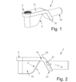
- Fig. 1 A first embodiment of a siphon device 1 is shown schematically in a perspective view.
- the siphon device 1 is particularly suitable for a washing area, such as a vanity unit, a shower, or a bathtub, in the sanitary area.
- a washing area such as a vanity unit, a shower, or a bathtub
- it can also be used, for example, in a kitchen sink or anywhere where a liquid can drain from a container, forming an odor trap.
- the siphon device 1 according to Fig. 1 is in Fig. 2 in a schematic side view, in Fig. 3 in a schematic plan view and in Fig. 4 in a longitudinal section IV - IV according to Fig. 3 It should be noted that in all figures the hatching symbolizing a section has been omitted for the sake of simplicity and better clarity.
- the siphon device 1 has a tubular connecting part 2 which can be connected to a washing area (not shown in detail) and a deflecting part 3 which is connected to the connecting part 2. With the aid of the deflecting part 3, a liquid 4 flowing through the siphon device 1, such as water, can be collected to form an odor trap (see Fig. 4 ).
- Connecting part 2 and deflecting part 3 are designed such that the flow velocity in deflecting part 3 is higher than that in connecting part 2.
- the ratio of the flow cross-section of the connecting part 2 to the flow cross-section of the deflecting part 3 is between 5:1 and 1.5:1, preferably between 4:1 and 2:1, particularly preferably 3:1.
- the connecting part 2 has a flow cross-section with a circular cross-sectional area 5
- the deflecting part 3 has a flow channel 6 with a cross-sectional area in the form of an elongated hole 7.
- An elongated hole refers to an elongated bore. The narrow sides of the elongated hole are closed off by semicircles whose diameters correspond to the width of the elongated hole. The long sides of the elongated hole run parallel to one another.
- the diameter 10 of the circular cross-sectional area 5 of the connecting part 2 corresponds to the length 11 of the slot 7 of the flow channel 6.
- the flow channel 6 of the deflection part 3 has, in the region of its junction with the connecting part 2, a rounded upper side 12 which merges into the circular flow cross-section of the connecting part 2.
- the radius 13 of the rounded upper side 12 of the flow channel 6 of the deflection part 3 corresponds to that of a further deflection 14. Furthermore, the radius 13 of the rounded upper side 12 corresponds to the radius of each inner curve 15, 16 of the flow channel 6 of the deflection part 3. The radius of each inner curve 15, 16 further corresponds approximately to the height 17 of the flow channel 6 of the deflection part 3. Furthermore, the radius 20 of each outer curve 21, 22 of the flow channel 6 of the deflection part 3 corresponds approximately to twice the height 17 of the flow channel 6 of the deflection part 3.
- the deflection part 3 has a drain pipe 24 at its end 23 opposite the connection part 2.
- the diameter 25 of the drain pipe 24 corresponds approximately to the length 11 of the slot 7 of the flow channel 6 of the deflection part 3, as shown in Fig. 3 is illustrated.
- Fig. 2 shows that the longitudinal axes 26, 27 of the drain pipe 24 and the deflection part 3 enclose an angle 30 of approximately 120°.
- Fig. 4 illustrates that the drain pipe 24 with its entire cross-sectional area opens into the flow channel 6 of the deflection part 3 just below the further deflection 14.
- the siphon device 1 has a total height 31 of approximately 80 mm with a sealing liquid height 32 of approximately 50 mm (see Fig. 4 ).
- the siphon device is particularly suitable for use in combination with a valve device with an integrated overflow valve. In this case, as described in the Fig. 1 to 9 shown, a lifting rod which is not shown in detail and is described in relation to the state of the art is completely omitted.
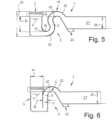
- the Fig. 5 The siphon device 1 shown has an inner curve 15, which merges directly into the outer curve 22 of the further deflection 14. This allows the siphon device to be Fig. 5 shown embodiment has a shorter overall length than that shown in the Fig. 1 to 4 shown embodiment.
- FIG. 6 Another embodiment of the siphon device is shown in Fig. 6 shown schematically in longitudinal section.
- the rounding in the transition area between the connecting part 2 and the deflection part 3 is omitted.
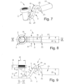
- FIG. 7 A fourth embodiment of the siphon device 1 is shown in the Fig. 7 to 9 shown, where Fig. 7 a schematic perspective view, Fig. 8 a schematic plan view of the siphon device according to Fig. 7 and Fig. 9 a schematic longitudinal section IX - IX in Fig. 8 show.
- the embodiment of the siphon device 1 shown has a housing 33 that encloses all parts of the siphon device except the drain pipe. This creates a compact external appearance of the siphon device with an exclusive design.
- the housing 33 is now omitted. Otherwise, the latter embodiment corresponds to that shown in the Fig. 1 to 4
- the siphon device is shown in the Fig. 7 to 9 is therefore minimalist in design with extremely low material requirements.
- the height 17 of the flow channel 6 can be, for example, 13.5 mm, and the length 11 of the elongated hole is preferably 37 mm. Accordingly, the diameter 10 of the circular cross-sectional area of the connecting part 2 and the diameter 25 of the drain pipe 24 can also be approximately 37 mm.
- the entire siphon device 1 is manufactured in one piece. Ideal flow behavior is achieved, particularly in the drain pipe, when the flow cross-section there is approximately half filled with liquid and the space above the liquid is ventilated, as explained above.
Landscapes
- Engineering & Computer Science (AREA)
- Health & Medical Sciences (AREA)
- Life Sciences & Earth Sciences (AREA)
- Hydrology & Water Resources (AREA)
- Public Health (AREA)
- Water Supply & Treatment (AREA)
- Environmental & Geological Engineering (AREA)
- Sink And Installation For Waste Water (AREA)
Description
- Die Erfindung bezieht sich auf eine Siphoneinrichtung, insbesondere für einen Waschplatz im Sanitärbereich, mit einem rohrförmigen, mit dem Waschplatz verbindbaren Anschlussteil und einem mit dem Anschlussteil verbundenen Umlenkteil, mittels dem eine durch die Siphoneinrichtung strömende Flüssigkeit zwecks Ausbildung eines Geruchsverschlusses aufstaubar ist.
- Eine solche Siphoneinrichtung ist aus der Praxis bekannt. Diese Siphoneinrichtung weist mehrere miteinander verbundene Rohre mit kreisförmigen Querschnitt auf, wobei ein Anschlussrohr, etwa senkrecht angeordnet, mit einem Waschplatz verbunden ist, sich üblicherweise mehr als 20 cm weg vom Waschplatz nach unten erstreckt, woran sich eine erste Krümmung zum Umlenken einer durch die Siphoneinrichtung strömenden Flüssigkeit um etwa 180° nach oben zum Waschplatz hin und eine zweite Krümmung zum Umlenken der Flüssigkeit um etwa 90° zu einer Wand hin anschließen. In vielen Fällen sind ferner eine Überlaufvorrichtung des Waschplatzes und ein Hebegestänge für eine Ventileinrichtung zum Aufstauen der Flüssigkeit im Waschplatz mit der Siphoneinrichtung verbunden. Dadurch kann es zur Ausbreitung unangenehmer Gerüche kommen. Mit starken Reinigungsmitteln lassen sich schlechte Gerüche zwar überdecken, allerdings bleibt der oft nur schwer zugängliche Bakterienherd häufig bestehen. Im Übrigen verschmutzen derartige Siphoneinrichtungen relativ schnell, da Schmutz in der Siphoneinrichtung häufig hängen- und liegenbleibt. Ein Reinigen der Siphoneinrichtung bis zum Spiegel der im Siphon befindlichen Sperrflüssigkeit ist ohne eine Demontage der gesamten Einrichtung kaum möglich. Aufgrund ihrer Gestaltung und Abmessungen ist in Schubladen unterhalb des Waschplatzes, wie zum Beispiel bei einem Waschtisch, ein Schubladenausschnitt vorzusehen, der die Ablagefläche der Schublade meist deutlich reduziert. Weitere Siphoneinrichtungen sind zum Beispiel aus
DE 201 00 826 U1 ,DE 20 2014 007392 U1 undDE 10 2009 043 859 A1 bekannt. - Der Erfindung liegt die Aufgabe zugrunde, eine Siphoneinrichtung zu schaffen, die einfacher handhabbar ist.
- Diese Aufgabe wird erfindungsgemäß durch eine Siphoneinrichtung mit den Merkmalen des Anspruchs 1 gelöst. Vorteilhafte Ausgestaltungen der Erfindung sind in den abhängigen Ansprüchen beschrieben.
- Die Siphoneinrichtung hat ein rohrförmiges, mit dem Waschplatz verbindbares Anschlussteil und ein mit dem Anschlussteil verbundenes Umlenkteil. Mithilfe des Umlenkteils ist eine durch die Siphoneinrichtung strömende Flüssigkeit zwecks Ausbildung eines Geruchsverschlusses aufstaubar. Erfindungsgemäß sind Anschlussteil und Umlenkteil derart ausgebildet, dass die Strömungsgeschwindigkeit im Umlenkteil höher als diejenige im Anschlussteil ist. Eine höhere Strömungsgeschwindigkeit im Umlenkteil begünstigt Selbstreinigungseffekte, so dass sich Schmutzteilchen weniger leicht an Innenwänden der Siphoneinrichtung anlagern können. Durch die Erhöhung der Strömungsgeschwindigkeit werden ferner im Anschlussteil sich befindende Schmutzpartikel leichter angesaugt und durch das Umlenkteil abtransportiert. Damit ist auch die Gefahr der Ausbildung eines Biofilms (Bakterienherd) an Innenwänden der Siphoneinrichtung verringert, was sich positiv auf die Entstehung und Verbreitung unangenehmer Gerüche auswirkt. Gesundheitsschädliche Spezies können sich daher weniger leicht in der Siphoneinrichtung ansiedeln. Damit ist die erfindungsgemäße Siphoneinrichtung leichter und unproblematischer handhabbar.
- Vorteilhafterweise beträgt das Verhältnis von Strömungsquerschnitt des Anschlussteils zu Strömungsquerschnitt des Umlenkteils zwischen 5 : 1 und 1,5 : 1, bevorzugt zwischen 4 : 1 und 2 : 1, besonders bevorzugt 3 : 1. Dieser Weiterbildung liegt das Bernoulli-Prinzip zugrunde, wonach der Druck, der von einer Flüssigkeit ausgeübt wird, umgekehrt proportional zu ihrer Strömungsgeschwindigkeit ist und die Summe aus Geschwindigkeit und Druck in strömenden Flüssigkeiten konstant ist.
- Eine Querschnittverringerung führt also auf einfache Art und Weise im Bereich des Umlenkteils zu einer Geschwindigkeitserhöhung für die die Siphoneinrichtung durchströmende Flüssigkeit, so dass sich Schmutzpartikel weniger leicht an Innenwänden ablagern können. Auch insofern ist daher die erfindungsgemäße Siphoneinrichtung leichter handhabbar. Die vorgenannten Verhältnisse der Strömungsquerschnitte zueinander begünstigen ferner auch einen Durchsatz, wie er durch moderne Siphoneinrichtungen in der Praxis gefordert wird. Diese Weiterbildung basiert ferner auf der Erkenntnis, dass eine Selbstreinigung von Rohrleitungen insbesondere dann in einer Siphoneinrichtung erreicht wird, wenn periodisch eine Strömungsgeschwindigkeit von etwa 0,7 m/s vorliegt.
- Die zuvor beschriebene Erhöhung der Strömungsgeschwindigkeit lässt sich besonders einfach dadurch erreichen, dass das Anschlussteil einen Strömungsquerschnitt mit kreisförmiger Querschnittsfläche und das Umlenkteil einen Strömungskanal mit einer Querschnittsfläche in Form eines Langlochs hat, wobei der Durchmesser der kreisförmigen Querschnittsfläche des Anschlussteils der Länge des Langlochs des Strömungskanals entspricht. Dadurch können im Strömungsquerschnitt Vorsprünge, Rücksprünge, Kanten oder Zwickel, die sämtlich das Anlagern von Schmutz begünstigen, weitgehend vermieden werden. Schmutzpartikel können deshalb weniger leicht hängen- und liegenbleiben; zudem ist eine Reinigung aufgrund der kontinuierlichen Übergänge leichter möglich.
- Vorteilhafterweise mündet das Umlenkteil unter einem Winkel von etwa 90° in das Anschlussteil ein. Aufgrund der 90°-Umlenkung im Bereich zwischen Anschlussteil und Umlenkteil ist üblicherweise die Strömungsgeschwindigkeit am Rand erhöht, was das Abtransportieren von Schmutzteilchen begünstigen und ein Anlagern der Teilchen an der Innenwand weitgehend verhindern kann. Die vorerwähnte abrupte Änderung der Strömungsrichtung kann auch dazu beitragen, ein Anlagern von Schmutz in Teilen der Siphoneinrichtung zu reduzieren.
- Gemäß einer bevorzugten Weiterbildung weist der Strömungskanal des Umlenkteils im Bereich seiner Einmündung in das Anschlussteil eine abgerundete, in den Strömungsquerschnitt des Anschlussteils übergehende Oberseite auf, wobei vorzugsweise der Radius der abgerundeten Oberseite des Strömungskanals des Umlenkteils demjenigen einer weiteren Umlenkung im Strömungskanal des Umlenkteils entspricht. Durch die abgerundete Oberseite kann der Strömungsquerschnitt für die aus dem Anschlussteil in das Umlenkteil strömende Flüssigkeit weitgehend kontinuierlich reduziert werden. Dadurch kann das Auftreten von Ansaugeffekten begünstigt sein.
- Gemäß einer besonders bevorzugten Ausführungsform der Erfindung entspricht der Radius jeder inneren Rundung des Strömungskanals des Umlenkteils etwa der Höhe des Strömungskanals des Umlenkteils und der Radius jeder äußeren Rundung des Strömungskanals des Umlenkteils etwa der doppelten Höhe des Strömungskanals des Umlenkteils, wie dies nachfolgend noch erläutert wird. Dieser Weiterbildung liegt zusammen mit der vorerwähnten Weiterbildung weitgehend identischer Radien in den Umlenkungen die Erkenntnis zugrunde, dass eine laminare Strömungsführung der Flüssigkeit durch die Siphoneinrichtung hohe Abflussleistungen und damit hohe Durchsätze durch die Siphoneinrichtung gewährleisten kann. Auch diese Weiterbildung kann damit zu besseren Selbstreinigungseffekten und damit zu einer leichteren Handhabbarkeit der Siphoneinrichtung beitragen.
- Vorteilhafterweise weist das Umlenkteil an seinem dem Anschlussteil gegenüber liegenden Ende ein Abflussrohr mit einem Durchmesser auf, der der Länge des Langlochs des Strömungskanals des Umlenkteils etwa entspricht. Damit kann auch der Übergang von dem Langloch-Strömungsquerschnitt des Umlenkteils in den kreisförmigen Strömungsquerschnitt des Abflussrohres ohne Vorsprünge, Rücksprünge, Kanten, Zwickel oder der gleichen und damit kontinuierlich ausgebildet sein. Auch diese Weiterbildung kann zu einer laminaren Flüssigkeitsströmung durch die Siphoneinrichtung und damit zu hohen Abflussleistungen beitragen.
- Gemäß einer bevorzugten Weiterbildung schließen die Längsachsen von Abflussrohr und Umlenkteil einen Winkel von etwa 120° ein und mündet das Abflussrohr mit seiner gesamten Querschnittsfläche unterhalb der weiteren Umlenkung in den Strömungskanal des Umlenkteils ein. Insofern findet im Bereich des Übergangs zum Abflussrohr eine Querschnittserweiterung ausschließlich in der Höhe statt. Dadurch bleibt das Anschlussrohr belüftet, so dass keine Saugwirkung beispielsweise auf die Sperrflüssigkeit in der Siphoneinrichtung entstehen kann, wenn in einem Fallrohr, mit dem das Abflussrohr verbunden ist, weitere Spülungen betätigt werden. Bei nicht strömender Flüssigkeit ist der Bereich an der oberen Rundung des rohrförmigen Strömungsquerschnitts im Abflussrohr lüftet, so dass die Entstehung eines Luftkissens weitgehend verhindert ist.
- Gemäß einer bevorzugten Weiterbildung hat die Siphoneinrichtung eine Gesamtbauhöhe von etwa 80 mm bei einer Sperrflüssigkeitshöhe von etwa 50 mm. Diese Weiterbildung trägt mit zu einer deutlich vereinfachten Handhabbarkeit der erfindungsgemäßen Siphoneinrichtung bei. Zum einen legt die Flüssigkeit in der Siphoneinrichtung damit sehr kurze Wege zurück. Sollte eine Reinigung der Siphoneinrichtung erforderlich sein, sind nur wenige Flächen einer Reinigung zu unterziehen. Zum anderen kann der zuvor in Bezug auf den Stand der Technik erwähnte Schubladenausschnitt vollständig entfallen, so dass für eine Schublade die gesamte Fläche als Ablagefläche zur Verfügung steht. Dies hat auch Vorteile bei der Herstellung und Handhabung von unterhalb von Waschtischen angebrachten Schränken. Ferner ist eine derartige Siphoneinrichtung ohne weiteres unterfahrbar, was für Menschen, die in einem Rollstuhl zum Waschplatz fahren, eine große Erleichterung darstellt. Ferner ist eine solche Siphoneinrichtung sehr einfach montierbar. Letztlich kann die gesamte Siphoneinrichtung einstückig ausgebildet sein. Es ist klar, dass eine derartige Siphoneinrichtung einen geringen Materialverbrauch hat und insofern auch kostengünstig hergestellt werden kann. Auch Teile, die unabsichtlich in die Siphoneinrichtung hineinfallen, können aus dieser ohne großen Aufwand wieder entfernt werden. Eine solche Siphoneinrichtung ist auch zum Anbringen an Waschplätzen, wie zum Beispiel Duschen und Badewannen, geeignet.
- Ausführungsbeispiele des Erfindungsgegenstandes werden nachfolgend anhand der Zeichnung näher erläutert. Es zeigen:
- Fig. 1
- eine schematische, perspektivische Ansicht einer Siphoneinrichtung gemäß einer ersten Ausführungsform;
- Fig. 2
- eine schematische Seitenansicht der Siphoneinrichtung gemäß
Fig. 1 ; - Fig. 3
- eine schematische Draufsicht auf die Siphoneinrichtung gemäß
Fig. 1 ; - Fig. 4
- einen Längsschnitt IV - IV in
Fig. 3 ; - Fig. 5
- einen schematischen Längsschnitt durch eine Siphoneinrichtung gemäß einer zweiten Ausführungsform;
- Fig. 6
- einen schematischen Längsschnitt durch eine Siphoneinrichtung gemäß einer dritten Ausführungsform;
- Fig. 7
- eine schematische, perspektivische Ansicht einer Siphoneinrichtung gemäß einer vierten Ausführungsform;
- Fig. 8
- eine schematische Draufsicht auf die Siphoneinrichtung gemäß
Fig. 7 ; und - Fig. 9
- einen schematischen Längsschnitt IX - IX in
Fig. 8 . - In
Fig. 1 ist eine erste Ausführungsform einer Siphoneinrichtung 1 schematisch in einer perspektivischen Ansicht gezeigt. Die Siphoneinrichtung 1 ist insbesondere für einen Waschplatz, wie zum Beispiel einen Waschtisch, eine Dusche oder eine Badewanne, im Sanitärbereich geeignet. Sie kann aber auch beispielsweise bei einer Spüle in einer Küche und überall da zum Einsatz kommen, wo eine Flüssigkeit unter Ausbildung eines Geruchsverschlusses aus einem Behältnis ablaufen kann. - Die Siphoneinrichtung 1 gemäß
Fig. 1 ist inFig. 2 in einer schematischen Seitenansicht, inFig. 3 in einer schematischen Draufsicht und inFig. 4 in einem Längsschnitt IV - IV gemäßFig. 3 dargestellt. Es wird darauf hingewiesen, dass in sämtlichen Figuren die einen Schnitt symbolisierenden Schraffuren der Einfachheit und besseren Übersicht halber weggelassen sind. - Die Siphoneinrichtung 1 hat ein rohrförmiges, mit einem nicht näher gezeigten Waschplatz verbindbares Anschlussteil 2 und ein mit dem Anschlussteil 2 verbundenes Umlenkteil 3. Mithilfe des Umlenkteils 3 ist eine durch die Siphoneinrichtung 1 strömende Flüssigkeit 4, wie zum Beispiel Wasser, zwecks Ausbildung eines Geruchsverschlusses aufstaubar (siehe
Fig. 4 ). Anschlussteil 2 und Umlenkteil 3 sind derart ausgebildet, dass die Strömungsgeschwindigkeit im Umlenkteil 3 höher als diejenige im Anschlussteil 2 ist. - Um eine Erhöhung der Strömungsgeschwindigkeit zu erreichen, beträgt das Verhältnis von Strömungsquerschnitt des Anschlussteils 2 zu Strömungsquerschnitt des Umlenkteils 3 zwischen 5 : 1 und 1,5 : 1, bevorzugt zwischen 4 : 1 und 2 : 1, besonders bevorzugt 3 : 1. Das Anschlussteil 2 hat einen Strömungsquerschnitt mit einer kreisförmigen Querschnittsfläche 5 und das Umlenkteil 3 einen Strömungskanal 6 mit einer Querschnittsfläche in Form eines Langlochs 7. Ein Langloch bezeichnet eine längliche Bohrung. Die schmalen Seiten des Langlochs werden durch Halbkreise abgeschlossen, deren Durchmesser der Breite des Langlochs entsprechen. Die Längsseiten des Langloches verlaufen parallel zueinander.
- Der Durchmesser 10 der kreisförmigen Querschnittsfläche 5 des Anschlussteils 2 entspricht der Länge 11 des Langlochs 7 des Strömungskanals 6. Wie näher in
Fig. 4 gezeigt weist der Strömungskanal 6 des Umlenkteils 3 im Bereich seiner Einmündung in das Anschlussteil 2 eine abgerundete, in den kreisförmigen Strömungsquerschnitt des Anschlussteils 2 übergehende Oberseite 12 auf. - Der Radius 13 der abgerundeten Oberseite 12 des Strömungskanals 6 des Umlenkteils 3 entspricht demjenigen einer weiteren Umlenkung 14. Ferner entspricht der Radius 13 der abgerundeten Oberseite 12 dem Radius jeder inneren Rundung 15, 16 des Strömungskanals 6 des Umlenkteils 3. Der Radius jeder inneren Rundung 15, 16 entspricht ferner etwa der Höhe 17 des Strömungskanals 6 des Umlenkteils 3. Außerdem entspricht der Radius 20 jeder äußeren Rundung 21, 22 des Strömungskanals 6 des Umlenkteils 3 etwa der doppelten Höhe 17 des Strömungskanals 6 des Umlenkteils 3.
- Wie in sämtlichen Figuren angedeutet weist das Umlenkteil 3 an seinem dem Anschlussteil 2 gegenüber liegenden Ende 23 ein Abflussrohr 24 auf. Der Durchmesser 25 des Abflussrohres 24 entspricht etwa der Länge 11 des Langlochs 7 des Strömungskanals 6 des Umlenkteils 3, wie dies in
Fig. 3 veranschaulicht ist. -
Fig. 2 zeigt, dass die Längsachsen 26, 27 von Abflussrohr 24 und Umlenkteil 3 einen Winkel 30 von etwa 120° einschließen.Fig. 4 verdeutlicht, dass das Abflussrohr 24 mit seiner gesamten Querschnittsfläche kurz unterhalb der weiteren Umlenkung 14 in den Strömungskanal 6 des Umlenkteils 3 einmündet. - Die Siphoneinrichtung 1 hat eine Gesamtbauhöhe 31 von etwa 80 mm bei einer Sperrflüssigkeitshöhe 32 von etwa 50 mm (siehe
Fig. 4 ). Die Siphoneinrichtung ist insbesondere in Kombination mit einer Ventileinrichtung mit in die Ventileinrichtung integriertem Überlaufventil einsetzbar. In diesem Fall kann, wie in denFig. 1 bis 9 gezeigt, ein nicht näher dargestelltes und in Bezug auf den Stand der Technik beschriebenes Hebegestänge vollständig entfallen. - In den
Fig. 5 und 6 sind weitere Ausführungsformen der Siphoneinrichtung jeweils im Längsschnitt schematisch dargestellt. - Die in
Fig. 5 gezeigte Siphoneinrichtung 1 hat eine innere Rundung 15, die unmittelbar in die äußere Rundung 22 der weiteren Umlenkung 14 übergeht. Dadurch kann die Siphoneinrichtung gemäß der inFig. 5 gezeigten Ausführungsform eine kürzere Baulänge als die in denFig. 1 bis 4 gezeigte Ausführungsform aufweisen. - Eine andere Ausführungsform der Siphoneinrichtung ist in
Fig. 6 schematisch im Längsschnitt gezeigt. Bei dieser Ausführungsform entfällt die Abrundung im Übergangsbereich zwischen Anschlussteil 2 und Umlenkteil 3. Insofern ist hier keine abgerundete Oberseite 12 wie im Falle der in denFig. 1 bis 5 gezeigten Ausführungsformen vorhanden. Dadurch kann sich die Baulänge der Siphoneinrichtung noch weiter verkürzen. - Eine vierte Ausführungsform der Siphoneinrichtung 1 ist in den
Fig. 7 bis 9 dargestellt, wobeiFig. 7 eine schematische perspektivische Ansicht,Fig. 8 eine schematische Draufsicht auf die Siphoneinrichtung gemäßFig. 7 und Fig. 9 einen schematischen Längsschnitt IX - IX inFig. 8 zeigen. - Gemäß der in den
Fig. 1 bis 4 gezeigten Ausführungsform der Siphoneinrichtung 1 hat diese ein Gehäuse 33, das sämtliche Teile der Siphoneinrichtung ausgenommen das Abflussrohr umgibt. Dadurch entsteht ein kompaktes äußeres Erscheinungsbild der Siphoneinrichtung in einem exklusiven Design. - In der in den
Fig. 7 bis 9 gezeigten Ausführungsform ist nun das Gehäuse 33 weggelassen. Ansonsten entspricht die letztgenannte Ausführungsform derjenigen, wie sie in denFig. 1 bis 4 dargestellt ist. Die Siphoneinrichtung gemäß denFig. 7 bis 9 ist daher minimalistisch bei einem äußerst geringen Materialaufwand aufgebaut. - Die Höhe 17 des Strömungskanals 6 kann beispielsweise 13,5 mm betragen, die Länge 11 des Langlochs beträgt vorzugsweise 37 mm. Insofern können auch der Durchmesser 10 der kreisförmigen Querschnittsfläche des Anschlussteils 2 und der Durchmesser 25 des Abflussrohres 24 etwa 37 mm betragen.
- Gemäß einer bevorzugten Ausführungsform ist die gesamte Siphoneinrichtung 1 einstückig hergestellt. Ein ideales Fließverhalten ergibt sich insbesondere im Abflussrohr dann, wenn der Strömungsquerschnitt dort etwa halb mit Flüssigkeit gefüllt ist und der oberhalb der Flüssigkeit befindliche Raum belüftet ist, wie dies vorstehend erläutert wurde.
- Damit ist eine Siphoneinrichtung geschaffen, die selbstreinigend aufgebaut, einfach zu reinigen, relativ preiswert herstellbar ist, wenig Raum in Anspruch nimmt und unangenehme Gerüche vermeidet und insofern einfacher handhabbar ist.
Claims (9)
- Siphoneinrichtung, insbesondere für einen Waschplatz im Sanitärbereich,mit einem rohrförmigen, mit dem Waschplatz verbindbaren Anschlussteil (2) und einem mit dem Anschlussteil (2) verbundenen Umlenkteil (3), mittels dem eine durch die Siphoneinrichtung (1) strömende Flüssigkeit (4) zwecks Ausbildung eines Geruchsverschlusses aufstaubar ist,wobei das Anschlussteil (2) einen Strömungsquerschnitt mit einer Querschnittsfläche (5) und das Umlenkteil (3) einen Strömungskanal (6) mit einer Querschnittsfläche hat, wobei die Querschnittsfläche des Umlenkteils (3) kleiner ist als die Querschnittsfläche (5) des Anschlussteils, wodurch die Strömungsgeschwindigkeit im Umlenkteil (3) höher als diejenige im Anschlussteil (2) ist,dadurch gekennzeichnet, dass die Querschnittsfläche (5) des Strömungsquerschnitts des Anschlussteils kreisförmig und die Querschnittfläche des Strömungskanals (6) des Umlenkteils (3) in Form eines Langlochs (7) ist, wobei die schmalen Seiten des Langlochs (7) durch Halbkreise abgeschlossen sind, deren Durchmesser der Breite des Langlochs (7) entsprechen, und wobei der Durchmesser (10) der kreisförmigen Querschnittsfläche (5) des Anschlussteils (2) der Länge (11) des Langlochs (7) des Strömungskanals (6) entspricht.
- Siphoneinrichtung nach Anspruch 1, dadurch gekennzeichnet, dass das Verhältnis von Strömungsquerschnitt des Anschlussteils (2) zu Strömungsquerschnitt des Umlenkteils (3) zwischen 5 : 1 und 1,5 : 1, bevorzugt zwischen 4 : 1 und 2 : 1, besonders bevorzugt 3 : 1, beträgt.
- Siphoneinrichtung nach Anspruch 1 oder 2, dadurch gekennzeichnet, dass das Umlenkteil (3) unter einem Winkel von etwa 90° in das Anschlussteil (2) einmündet.
- Siphoneinrichtung nach einem der Ansprüche 1 bis 3, dadurch gekennzeichnet, dass der Strömungskanal (6) des Umlenkteils (3) im Bereich seiner Einmündung in das Anschlussteil (2) eine abgerundete, in den Strömungsquerschnitt des Anschlussteils (2) übergehende Oberseite (12) aufweist.
- Siphoneinrichtung nach Anspruch 4, dadurch gekennzeichnet, dass der Radius (13) der abgerundeten Oberseite (12) des Strömungskanals (6) des Umlenkteils (3) demjenigen einer weiteren Umlenkung (14) im Strömungskanal (6) des Umlenkteils (3) entspricht.
- Siphoneinrichtung nach Anspruch 5, dadurch gekennzeichnet, dass der Radius jeder inneren Rundung (15, 16) des Strömungskanals (6) des Umlenkteils (3) einer Höhe (17) des Strömungskanals (6) des Umlenkteils (3) und der Radius jeder äußeren Rundung (21, 22) des Strömungskanals (6) des Umlenkteils (3) der doppelten Höhe (17) des Strömungskanals (6) des Umlenkteils (3) entspricht.
- Siphoneinrichtung nach einem der vorhergehenden Ansprüche, dadurch gekennzeichnet, dass das Umlenkteil (3) an seinem dem Anschlussteil (2) gegenüber liegenden Ende (23) ein Abflussrohr (24) mit einem Durchmesser (25) aufweist, der der Länge (11) des Langlochs (7) des Strömungskanals (6) des Umlenkteils (3) etwa entspricht.
- Siphoneinrichtung nach den Ansprüchen 5 und 7, dadurch gekennzeichnet, dass die Längsachsen (26, 27) von Abflussrohr (24) und Umlenkteil (3) einen Winkel (30) von etwa 120° einschließen und das Abflussrohr (24) mit seiner gesamten Querschnittsfläche unterhalb der weiteren Umlenkung (14) in den Strömungskanal (6) des Umlenkteils (3) einmündet.
- Siphoneinrichtung nach einem der vorhergehenden Ansprüche, gekennzeichnet durch eine Gesamtbauhöhe (31) von etwa 80 mm bei einer Sperrflüssigkeitshöhe (32) von etwa 50 mm.
Applications Claiming Priority (1)
| Application Number | Priority Date | Filing Date | Title |
|---|---|---|---|
| DE102019001754.4A DE102019001754A1 (de) | 2019-03-11 | 2019-03-11 | Siphoneinrichtung |
Publications (3)
| Publication Number | Publication Date |
|---|---|
| EP3708725A1 EP3708725A1 (de) | 2020-09-16 |
| EP3708725C0 EP3708725C0 (de) | 2025-03-12 |
| EP3708725B1 true EP3708725B1 (de) | 2025-03-12 |
Family
ID=68944195
Family Applications (1)
| Application Number | Title | Priority Date | Filing Date |
|---|---|---|---|
| EP19216941.5A Active EP3708725B1 (de) | 2019-03-11 | 2019-12-17 | Siphoneinrichtung |
Country Status (2)
| Country | Link |
|---|---|
| EP (1) | EP3708725B1 (de) |
| DE (1) | DE102019001754A1 (de) |
Families Citing this family (2)
| Publication number | Priority date | Publication date | Assignee | Title |
|---|---|---|---|---|
| EP3828352A1 (de) * | 2019-11-27 | 2021-06-02 | Gerig Design AG | Siphon für einen ablauf |
| FR3120078B1 (fr) * | 2021-02-22 | 2023-11-03 | Ayor Water And Heating Solutions | Dispositif d’évacuation de fluide à encombrement réduit |
Citations (4)
| Publication number | Priority date | Publication date | Assignee | Title |
|---|---|---|---|---|
| DE102009003390A1 (de) * | 2008-02-01 | 2009-08-06 | Illbruck Sanitärtechnik GmbH | Duschbodenelement |
| WO2009115704A2 (fr) * | 2008-02-29 | 2009-09-24 | Logiplast Eurl | Ensemble bonde/siphon d'evacuation compose de plusieurs gardes d'eau |
| DE102009043859A1 (de) * | 2008-08-26 | 2010-04-01 | Illbruck Sanitärtechnik GmbH | Schaumstoff-Duschbodenelement |
| EP2995729A1 (de) * | 2014-09-10 | 2016-03-16 | Geberit International AG | Bodenablauf mit Schaumstoffblock |
Family Cites Families (3)
| Publication number | Priority date | Publication date | Assignee | Title |
|---|---|---|---|---|
| AT370468B (de) * | 1981-10-06 | 1983-04-11 | Hutterer & Lechner Kg | Siphon aus kunststoff als geruchverschluss fuer brausetassen, badewannen u. dgl. |
| DE20100826U1 (de) * | 2001-01-17 | 2002-05-29 | Franz Viegener II GmbH & Co. KG, 57439 Attendorn | Ablauf mit Geruchsverschluss |
| DE202014007392U1 (de) * | 2014-09-10 | 2014-12-17 | Geberit International Ag | Wasserablauf mit Mehrfachsiphon-Geruchsverschluss |
-
2019
- 2019-03-11 DE DE102019001754.4A patent/DE102019001754A1/de active Pending
- 2019-12-17 EP EP19216941.5A patent/EP3708725B1/de active Active
Patent Citations (4)
| Publication number | Priority date | Publication date | Assignee | Title |
|---|---|---|---|---|
| DE102009003390A1 (de) * | 2008-02-01 | 2009-08-06 | Illbruck Sanitärtechnik GmbH | Duschbodenelement |
| WO2009115704A2 (fr) * | 2008-02-29 | 2009-09-24 | Logiplast Eurl | Ensemble bonde/siphon d'evacuation compose de plusieurs gardes d'eau |
| DE102009043859A1 (de) * | 2008-08-26 | 2010-04-01 | Illbruck Sanitärtechnik GmbH | Schaumstoff-Duschbodenelement |
| EP2995729A1 (de) * | 2014-09-10 | 2016-03-16 | Geberit International AG | Bodenablauf mit Schaumstoffblock |
Also Published As
| Publication number | Publication date |
|---|---|
| EP3708725A1 (de) | 2020-09-16 |
| DE102019001754A1 (de) | 2020-09-17 |
| EP3708725C0 (de) | 2025-03-12 |
Similar Documents
| Publication | Publication Date | Title |
|---|---|---|
| EP2045403B1 (de) | Ablaufgarnitur mit integriertem Überlauf | |
| EP2584107A1 (de) | Sanitäranordnung | |
| EP3708725B1 (de) | Siphoneinrichtung | |
| DE202008011010U1 (de) | Ablauf | |
| DE102008038274B3 (de) | Ablauf | |
| EP1170426A1 (de) | Absaugesiphon für eine Spüleinrichtung | |
| DE202015107000U1 (de) | Ablaufsystem | |
| WO2014138761A1 (de) | Ablaufelement für eine duschwanne | |
| DE102013102379A1 (de) | Ablaufanordnung | |
| DE10204683B4 (de) | Becken | |
| DE19749779A1 (de) | Geruchsverschluß für ein Abflußrohr, insbesondere für das Abflußrohr eines Waschbeckens, einer Duschwanne oder dergleichen | |
| DE102021117601A1 (de) | Waschbecken für Räume mit erhöhten Hygieneanforderungen und Waschtisch | |
| EP3567169B1 (de) | Ablaufgarnitur | |
| DE8906228U1 (de) | Einbaugeruchsverschluß | |
| EP4065786A1 (de) | Siphon für einen ablauf | |
| EP4071312B1 (de) | Vorrichtung für eine im boden eines raumes angeordnete ablaufvorrichtung sowie ablaufvorrichtung mit einer derartigen vorrichtung | |
| WO2025093528A1 (de) | Waschbecken | |
| DE102019001753A1 (de) | Ventilvorrichtung | |
| DE202012100932U1 (de) | Sanitäre Einrichtung | |
| DE69021691T2 (de) | Abflusssiphon für Sanitärapparat. | |
| EP3421676B1 (de) | Geruchsverschlusselement zum einbau in einen abfluss, insbesondere in den abfluss eines wasserlosen urinals | |
| DE202010000210U1 (de) | Rohrförmiger Ablauf und rohrförmiges Ablaufsystem für Wasserbecken | |
| EP4060135A1 (de) | Niedrigbauender unterputzspülkasten | |
| DE2204905B1 (de) | Geruchverschluss fuer sanitaerkoerper, insbesondere fuer waschbecken | |
| DE102012104325B3 (de) | Ablaufarmatur für ein Ablaufbecken, insbesondere Urinal, mit einem Absaugsiphon |
Legal Events
| Date | Code | Title | Description |
|---|---|---|---|
| PUAI | Public reference made under article 153(3) epc to a published international application that has entered the european phase |
Free format text: ORIGINAL CODE: 0009012 |
|
| STAA | Information on the status of an ep patent application or granted ep patent |
Free format text: STATUS: THE APPLICATION HAS BEEN PUBLISHED |
|
| AK | Designated contracting states |
Kind code of ref document: A1 Designated state(s): AL AT BE BG CH CY CZ DE DK EE ES FI FR GB GR HR HU IE IS IT LI LT LU LV MC MK MT NL NO PL PT RO RS SE SI SK SM TR |
|
| AX | Request for extension of the european patent |
Extension state: BA ME |
|
| STAA | Information on the status of an ep patent application or granted ep patent |
Free format text: STATUS: REQUEST FOR EXAMINATION WAS MADE |
|
| RAP1 | Party data changed (applicant data changed or rights of an application transferred) |
Owner name: BURGBAD AG |
|
| 17P | Request for examination filed |
Effective date: 20210209 |
|
| RBV | Designated contracting states (corrected) |
Designated state(s): AL AT BE BG CH CY CZ DE DK EE ES FI FR GB GR HR HU IE IS IT LI LT LU LV MC MK MT NL NO PL PT RO RS SE SI SK SM TR |
|
| STAA | Information on the status of an ep patent application or granted ep patent |
Free format text: STATUS: EXAMINATION IS IN PROGRESS |
|
| 17Q | First examination report despatched |
Effective date: 20220608 |
|
| GRAP | Despatch of communication of intention to grant a patent |
Free format text: ORIGINAL CODE: EPIDOSNIGR1 |
|
| STAA | Information on the status of an ep patent application or granted ep patent |
Free format text: STATUS: GRANT OF PATENT IS INTENDED |
|
| INTG | Intention to grant announced |
Effective date: 20241002 |
|
| GRAS | Grant fee paid |
Free format text: ORIGINAL CODE: EPIDOSNIGR3 |
|
| GRAA | (expected) grant |
Free format text: ORIGINAL CODE: 0009210 |
|
| STAA | Information on the status of an ep patent application or granted ep patent |
Free format text: STATUS: THE PATENT HAS BEEN GRANTED |
|
| AK | Designated contracting states |
Kind code of ref document: B1 Designated state(s): AL AT BE BG CH CY CZ DE DK EE ES FI FR GB GR HR HU IE IS IT LI LT LU LV MC MK MT NL NO PL PT RO RS SE SI SK SM TR |
|
| REG | Reference to a national code |
Ref country code: GB Ref legal event code: FG4D Free format text: NOT ENGLISH |
|
| REG | Reference to a national code |
Ref country code: CH Ref legal event code: EP |
|
| REG | Reference to a national code |
Ref country code: DE Ref legal event code: R096 Ref document number: 502019013037 Country of ref document: DE |
|
| REG | Reference to a national code |
Ref country code: IE Ref legal event code: FG4D Free format text: LANGUAGE OF EP DOCUMENT: GERMAN |
|
| U01 | Request for unitary effect filed |
Effective date: 20250410 |
|
| U07 | Unitary effect registered |
Designated state(s): AT BE BG DE DK EE FI FR IT LT LU LV MT NL PT RO SE SI Effective date: 20250417 |
|
| PG25 | Lapsed in a contracting state [announced via postgrant information from national office to epo] |
Ref country code: RS Free format text: LAPSE BECAUSE OF FAILURE TO SUBMIT A TRANSLATION OF THE DESCRIPTION OR TO PAY THE FEE WITHIN THE PRESCRIBED TIME-LIMIT Effective date: 20250612 |
|
| PG25 | Lapsed in a contracting state [announced via postgrant information from national office to epo] |
Ref country code: ES Free format text: LAPSE BECAUSE OF FAILURE TO SUBMIT A TRANSLATION OF THE DESCRIPTION OR TO PAY THE FEE WITHIN THE PRESCRIBED TIME-LIMIT Effective date: 20250312 |
|
| PG25 | Lapsed in a contracting state [announced via postgrant information from national office to epo] |
Ref country code: NO Free format text: LAPSE BECAUSE OF FAILURE TO SUBMIT A TRANSLATION OF THE DESCRIPTION OR TO PAY THE FEE WITHIN THE PRESCRIBED TIME-LIMIT Effective date: 20250612 |
|
| PG25 | Lapsed in a contracting state [announced via postgrant information from national office to epo] |
Ref country code: HR Free format text: LAPSE BECAUSE OF FAILURE TO SUBMIT A TRANSLATION OF THE DESCRIPTION OR TO PAY THE FEE WITHIN THE PRESCRIBED TIME-LIMIT Effective date: 20250312 |
|
| PG25 | Lapsed in a contracting state [announced via postgrant information from national office to epo] |
Ref country code: GR Free format text: LAPSE BECAUSE OF FAILURE TO SUBMIT A TRANSLATION OF THE DESCRIPTION OR TO PAY THE FEE WITHIN THE PRESCRIBED TIME-LIMIT Effective date: 20250613 |
|
| PG25 | Lapsed in a contracting state [announced via postgrant information from national office to epo] |
Ref country code: SM Free format text: LAPSE BECAUSE OF FAILURE TO SUBMIT A TRANSLATION OF THE DESCRIPTION OR TO PAY THE FEE WITHIN THE PRESCRIBED TIME-LIMIT Effective date: 20250312 |
|
| PG25 | Lapsed in a contracting state [announced via postgrant information from national office to epo] |
Ref country code: PL Free format text: LAPSE BECAUSE OF FAILURE TO SUBMIT A TRANSLATION OF THE DESCRIPTION OR TO PAY THE FEE WITHIN THE PRESCRIBED TIME-LIMIT Effective date: 20250312 |
|
| PG25 | Lapsed in a contracting state [announced via postgrant information from national office to epo] |
Ref country code: CZ Free format text: LAPSE BECAUSE OF FAILURE TO SUBMIT A TRANSLATION OF THE DESCRIPTION OR TO PAY THE FEE WITHIN THE PRESCRIBED TIME-LIMIT Effective date: 20250312 |
|
| PG25 | Lapsed in a contracting state [announced via postgrant information from national office to epo] |
Ref country code: SK Free format text: LAPSE BECAUSE OF FAILURE TO SUBMIT A TRANSLATION OF THE DESCRIPTION OR TO PAY THE FEE WITHIN THE PRESCRIBED TIME-LIMIT Effective date: 20250312 |
|
| PG25 | Lapsed in a contracting state [announced via postgrant information from national office to epo] |
Ref country code: IS Free format text: LAPSE BECAUSE OF FAILURE TO SUBMIT A TRANSLATION OF THE DESCRIPTION OR TO PAY THE FEE WITHIN THE PRESCRIBED TIME-LIMIT Effective date: 20250712 |