EP3708522B2 - Transportsystem für werkstoffplatten - Google Patents
Transportsystem für werkstoffplatten Download PDFInfo
- Publication number
- EP3708522B2 EP3708522B2 EP20157821.8A EP20157821A EP3708522B2 EP 3708522 B2 EP3708522 B2 EP 3708522B2 EP 20157821 A EP20157821 A EP 20157821A EP 3708522 B2 EP3708522 B2 EP 3708522B2
- Authority
- EP
- European Patent Office
- Prior art keywords
- movement path
- movement
- supported
- section
- transporting system
- Prior art date
- Legal status (The legal status is an assumption and is not a legal conclusion. Google has not performed a legal analysis and makes no representation as to the accuracy of the status listed.)
- Active
Links
Images


Classifications
-
- B—PERFORMING OPERATIONS; TRANSPORTING
- B65—CONVEYING; PACKING; STORING; HANDLING THIN OR FILAMENTARY MATERIAL
- B65G—TRANSPORT OR STORAGE DEVICES, e.g. CONVEYORS FOR LOADING OR TIPPING, SHOP CONVEYOR SYSTEMS OR PNEUMATIC TUBE CONVEYORS
- B65G47/00—Article or material-handling devices associated with conveyors; Methods employing such devices
- B65G47/34—Devices for discharging articles or materials from conveyor
- B65G47/46—Devices for discharging articles or materials from conveyor and distributing, e.g. automatically, to desired points
- B65G47/51—Devices for discharging articles or materials from conveyor and distributing, e.g. automatically, to desired points according to unprogrammed signals, e.g. influenced by supply situation at destination
- B65G47/5104—Devices for discharging articles or materials from conveyor and distributing, e.g. automatically, to desired points according to unprogrammed signals, e.g. influenced by supply situation at destination for articles
- B65G47/515—First In-Last Out systems [FILO]; Last In-First Out systems [LIFO]
- B65G47/5181—First In-Last Out systems [FILO]; Last In-First Out systems [LIFO] using stacking or destacking arrangements or stacks of articles or article-carriers
-
- B—PERFORMING OPERATIONS; TRANSPORTING
- B65—CONVEYING; PACKING; STORING; HANDLING THIN OR FILAMENTARY MATERIAL
- B65G—TRANSPORT OR STORAGE DEVICES, e.g. CONVEYORS FOR LOADING OR TIPPING, SHOP CONVEYOR SYSTEMS OR PNEUMATIC TUBE CONVEYORS
- B65G47/00—Article or material-handling devices associated with conveyors; Methods employing such devices
- B65G47/52—Devices for transferring articles or materials between conveyors i.e. discharging or feeding devices
- B65G47/64—Switching conveyors
- B65G47/641—Switching conveyors by a linear displacement of the switching conveyor
- B65G47/643—Switching conveyors by a linear displacement of the switching conveyor in a vertical plane
-
- B—PERFORMING OPERATIONS; TRANSPORTING
- B07—SEPARATING SOLIDS FROM SOLIDS; SORTING
- B07C—POSTAL SORTING; SORTING INDIVIDUAL ARTICLES, OR BULK MATERIAL FIT TO BE SORTED PIECE-MEAL, e.g. BY PICKING
- B07C5/00—Sorting according to a characteristic or feature of the articles or material being sorted, e.g. by control effected by devices which detect or measure such characteristic or feature; Sorting by manually actuated devices, e.g. switches
- B07C5/36—Sorting apparatus characterised by the means used for distribution
-
- B—PERFORMING OPERATIONS; TRANSPORTING
- B65—CONVEYING; PACKING; STORING; HANDLING THIN OR FILAMENTARY MATERIAL
- B65G—TRANSPORT OR STORAGE DEVICES, e.g. CONVEYORS FOR LOADING OR TIPPING, SHOP CONVEYOR SYSTEMS OR PNEUMATIC TUBE CONVEYORS
- B65G21/00—Supporting or protective framework or housings for endless load-carriers or traction elements of belt or chain conveyors
- B65G21/20—Means incorporated in, or attached to, framework or housings for guiding load-carriers, traction elements or loads supported on moving surfaces
- B65G21/22—Rails or the like engaging sliding elements or rollers attached to load-carriers or traction elements
-
- B—PERFORMING OPERATIONS; TRANSPORTING
- B65—CONVEYING; PACKING; STORING; HANDLING THIN OR FILAMENTARY MATERIAL
- B65G—TRANSPORT OR STORAGE DEVICES, e.g. CONVEYORS FOR LOADING OR TIPPING, SHOP CONVEYOR SYSTEMS OR PNEUMATIC TUBE CONVEYORS
- B65G37/00—Combinations of mechanical conveyors of the same kind, or of different kinds, of interest apart from their application in particular machines or use in particular manufacturing processes
- B65G37/005—Combinations of mechanical conveyors of the same kind, or of different kinds, of interest apart from their application in particular machines or use in particular manufacturing processes comprising two or more co-operating conveying elements with parallel longitudinal axes
-
- B—PERFORMING OPERATIONS; TRANSPORTING
- B65—CONVEYING; PACKING; STORING; HANDLING THIN OR FILAMENTARY MATERIAL
- B65G—TRANSPORT OR STORAGE DEVICES, e.g. CONVEYORS FOR LOADING OR TIPPING, SHOP CONVEYOR SYSTEMS OR PNEUMATIC TUBE CONVEYORS
- B65G43/00—Control devices, e.g. for safety, warning or fault-correcting
- B65G43/08—Control devices operated by article or material being fed, conveyed or discharged
-
- B—PERFORMING OPERATIONS; TRANSPORTING
- B65—CONVEYING; PACKING; STORING; HANDLING THIN OR FILAMENTARY MATERIAL
- B65G—TRANSPORT OR STORAGE DEVICES, e.g. CONVEYORS FOR LOADING OR TIPPING, SHOP CONVEYOR SYSTEMS OR PNEUMATIC TUBE CONVEYORS
- B65G2201/00—Indexing codes relating to handling devices, e.g. conveyors, characterised by the type of product or load being conveyed or handled
- B65G2201/02—Articles
- B65G2201/0214—Articles of special size, shape or weigh
- B65G2201/022—Flat
-
- B—PERFORMING OPERATIONS; TRANSPORTING
- B65—CONVEYING; PACKING; STORING; HANDLING THIN OR FILAMENTARY MATERIAL
- B65G—TRANSPORT OR STORAGE DEVICES, e.g. CONVEYORS FOR LOADING OR TIPPING, SHOP CONVEYOR SYSTEMS OR PNEUMATIC TUBE CONVEYORS
- B65G2201/00—Indexing codes relating to handling devices, e.g. conveyors, characterised by the type of product or load being conveyed or handled
- B65G2201/02—Articles
- B65G2201/0282—Wooden articles, e.g. logs, trunks or planks
-
- B—PERFORMING OPERATIONS; TRANSPORTING
- B65—CONVEYING; PACKING; STORING; HANDLING THIN OR FILAMENTARY MATERIAL
- B65G—TRANSPORT OR STORAGE DEVICES, e.g. CONVEYORS FOR LOADING OR TIPPING, SHOP CONVEYOR SYSTEMS OR PNEUMATIC TUBE CONVEYORS
- B65G2203/00—Indexing code relating to control or detection of the articles or the load carriers during conveying
- B65G2203/04—Detection means
- B65G2203/042—Sensors
-
- B—PERFORMING OPERATIONS; TRANSPORTING
- B65—CONVEYING; PACKING; STORING; HANDLING THIN OR FILAMENTARY MATERIAL
- B65G—TRANSPORT OR STORAGE DEVICES, e.g. CONVEYORS FOR LOADING OR TIPPING, SHOP CONVEYOR SYSTEMS OR PNEUMATIC TUBE CONVEYORS
- B65G57/00—Stacking of articles
- B65G57/02—Stacking of articles by adding to the top of the stack
- B65G57/11—Stacking of articles by adding to the top of the stack the articles being stacked by direct action of the feeding conveyor
-
- B—PERFORMING OPERATIONS; TRANSPORTING
- B65—CONVEYING; PACKING; STORING; HANDLING THIN OR FILAMENTARY MATERIAL
- B65G—TRANSPORT OR STORAGE DEVICES, e.g. CONVEYORS FOR LOADING OR TIPPING, SHOP CONVEYOR SYSTEMS OR PNEUMATIC TUBE CONVEYORS
- B65G59/00—De-stacking of articles
- B65G59/02—De-stacking from the top of the stack
- B65G59/026—De-stacking from the top of the stack with a stepwise upward movement of the stack
Definitions
- the invention relates to a transport system for material plates, via which a material plate can be transported on a movement path supported by rollers or circulating belts along a movement direction from a first treatment station to a second treatment station, wherein the transport system has at least one supply and/or discharge device within the movement path for material plates towards and/or away from the movement path.
- the invention also relates to a method for supplying and/or removing material plates in a transport system for material plates, via which a material plate can be transported on a movement path supported by rollers or circulating belts along a movement direction from a first treatment station to a second treatment station.
- Material boards are primarily understood to mean wood-based panels that have already been produced in a preferably continuous press and then cut with saws. Examples of suitable materials here are chipboard, MDF or OSB boards.
- the treatment stations in the general term primarily refer to cutting devices and grinding devices.
- the direction of movement can be from a grinding device to a final cutting device or from a plate cutting device to a grinding device.
- the movement path for the material plates is usually a flat roller conveyor or a travel path for the material plates supported by carrying belts.
- Other supports such as gas cushions or sliding surfaces are also to be covered by the invention.
- the supply and/or discharge devices were separate arrangements that were used at the beginning or end of a transport route, i.e. the movement path from a first to a second treatment station.
- a transport route i.e. the movement path from a first to a second treatment station.
- complex switch arrangements were necessary. For example, guide rollers or conveyor belts were adjusted in height in order to forward panels on different adjacent paths.
- a transport system according to the preamble of claim 1 and a method according to the preamble of claim 7 are known, for example, from US$2,981,399 known.
- the invention aims to keep the installation space of the transport system small despite having at least one supply or discharge device for wood-based panels.
- a section of the movement path supported by rollers or circulating belts is removable in a direction other than the movement direction and the transport system has a lifting arrangement arranged below the section, which is suitable for supplying material plates to the movement path and for picking them up from it.
- the basic idea is simply to move a part of the movement path, i.e. a section of the support rollers or conveyor belts, sideways and thus, in a space-saving manner, to lift and feed panels from below using the lifting arrangement or to pick up rejected panels on the lifting arrangement and move them downwards out of the movement path.
- the section must obviously be at least the length of a material plate in the direction of movement. Nevertheless, the effort is significantly less and saves more space than with the complicated switch arrangements of the past.
- the lifting arrangement is suitable for feeding material plates into and removing them from the movement path.
- the lifting arrangement has a support surface for at least one material plate.
- the stroke is designed so large that it extends from a pick-up position or delivery position at the lowest point to almost the path of movement. In the pick-up position or delivery position, at least one material plate can be easily brought in or taken away, for example with a transport vehicle.
- the lifting device is suitable for holding a stack of material plates.
- the transport system has drive elements which are suitable for moving the material plates from the movement path to the lifting arrangement or from the lifting arrangement to the movement path.
- the infeed and outfeed processes can be automated.
- the transport system has guide elements and centering elements.
- Such guiding and centering elements can be used at various points in the transport system
- the material plates must be centered in the direction of movement and aligned straight on the path of movement and placed on the lifting arrangement with edge precision.
- the transport system has a supply device and a discharge device, one of which can be used optionally.
- This arrangement offers the advantage that, in addition to the normal flow through the movement path from the first to the second treatment station, one of the two options, namely the introduction or the removal of material plates into the flow, can be switched.
- the supply device and the discharge device can be moved together.
- That the diversion device comprises the remote portion of the path of travel supported by rollers or revolving belts.
- the second function of a guidance device is assigned to the movement path supported by rollers or circulating belts, which has been removed for discharge.
- a quality detection sensor for the material plate is arranged in the running direction between the first treatment station and the section of the movement path supported by rollers or circulating belts.
- the quality of the material plate can therefore be detected before it reaches the discharge device. If the material plate is classified as B-goods based on the optical image of its surface or its dimensions, for example, the discharge device can be activated via a central control system.
- the object is finally achieved in terms of the method by the features of claim 7 and in particular in that a section of the movement path supported by rollers or circulating belts is removed in a direction other than the movement direction and a lifting arrangement arranged below the section introduces material plates into the movement path and picks them up from it.
- the lifting device picks up a stack of material plates and carries out working strokes of the same thickness as the material plate.
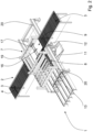
- Fig.1 shows the transport system 1 according to the invention in its throughput position in the direction of movement R.
- the material plates 10 are transported from a first treatment station B1, for example a grinding station, to a second treatment station B2, for example a sawing system, on a movement path 2.
- the treatment stations B1, B2 are only shown schematically here as a box.
- the movement path 2 can be supported, for example, by driven rollers 3 or revolving support belts 6.
- the first section from the treatment station B1 to a specific section 9 of the movement path 2 is implemented by a roller-supported movement path 3, just like the section from the specific section 9 to the second treatment station B2.
- the section 9 is implemented in the embodiment by a belt-supported movement section 5 formed.
- the entire movement path from the first treatment station B1 to the second treatment station B2 is defined here with the reference number 2.
- roller-supported movement paths are provided with the reference number 3 and belt-supported movement paths with the reference number 5.
- the section 9, which is essential to the invention, is given an additional reference number because of its importance and can be both belt-supported and roller-supported.
- the movement paths 3 and 5 are parts of the entire movement path 2.
- rollers 4 and belts 6 shown as examples are driven in order to enable easy transport of the material plates 10.
- the transport system 1 further comprises a lifting arrangement 11 below the section 9 of the movement path 2. Via a ramp, in this embodiment in the form of a chain-supported feed or removal 13, material plates can be fed to or removed from the support surface 12 of the lifting arrangement 11, even as a stack of plates.
- a switching frame 19 which can be moved on rails 20. It has two alternative end positions. In the first, it functions as a discharge device 8, in the other as a feed device 7 for material plates. It can also be said that one half of the switching frame 19 (in the Fig. 1 to 3 front) the diversion device 8 and the other half of the switching frame 19 (in the Fig. 1 to 3 rear) carries the feed device 7. These two positions are explained in more detail in the following figures.
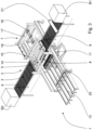
- Fig. 2 shows the transport system 1 with activated feed device 7.
- the switching frame was moved (to the front in the drawing).
- the conveyor belts 6 have thus been removed laterally from the area of section 9 of the movement path 2. This creates an opening in section 9 directly above the lifting arrangement 11.
- Material plates fed to the lifting arrangement 11, possibly also stacks of them step by step, are lifted until the top material plate has arrived just above the movement path.
- Claws 16 which can be moved in rails 17 grip one end of a material plate and pull the top material plate onto the roller-supported movement path 3 between section 9 and the second treatment station B2.
- the lifting arrangement can be moved upwards successively by the thickness of the material plate and the plates can be brought onto the movement path one after the other.
- Such a supply of material panels often occurs when panels have been placed in a warehouse, for example for the purpose of drying or cooling, before they can be transported to the second treatment station.
- the opposite process and thus the activation of the discharge device 8 is shown Fig.3 .
- the switching frame 19 has been moved back to its starting position.
- the rotating belts 6 are raised by a mechanism (not shown) so that material plates 10, coming from the first treatment station B1, are moved under the belt-supported movement path 5 in the area of section 9.
- the rotating belts 6 take on the task of a belt drive 15 or a guide and centering device 18 above the material plate 10 to be discharged (not shown). This may be clearer in the detailed view Fig.4
- This discharge device guides the material plate onto the stack of plates that is being formed on the support surface 12 of the lifting arrangement 11 and places it as the topmost material plate.
- the lifting arrangement moves downwards by the plate thickness for each new plate.
- rejection process is useful if the board does not meet the desired quality requirements.
- the rejection process can be automated if a quality detection sensor 21 is arranged between the first treatment station B1 and the section 9 of the movement path 2, the measurement signal of which can be passed on to the diversion device 8. If the quality detection sensor 21 detects that the board is damaged, for example, the belt-supported movement path 5 can be raised on the inlet side so that the rejected board is diverted from the web path 2 to the lifting arrangement 11.
- the roller or belt supported section 9 of the web path must be removed in a direction other than the direction of movement in order to make the corresponding process possible.
Landscapes
- Engineering & Computer Science (AREA)
- Mechanical Engineering (AREA)
- Separation, Sorting, Adjustment, Or Bending Of Sheets To Be Conveyed (AREA)
- Structure Of Belt Conveyors (AREA)
- Delivering By Means Of Belts And Rollers (AREA)
Description
- Die Erfindung betrifft ein Transportsystem für Werkstoffplatten, über welches eine Werkstoffplatte auf einem von Rollen oder umlaufenden Bändern unterstützten Bewegungspfad entlang einer Bewegungsrichtung von einer ersten Behandlungsstation zu einer zweiten Behandlungsstation transportierbar ist, wobei das Transportsystem wenigstens eine Zu- und/oder Ableiteinrichtung innerhalb des Bewegungspfades für Werkstoffplatten hin zu und/oder weg von dem Bewegungspfad aufweist.
- Die Erfindung betrifft außerdem ein Verfahren zum Zu- und/oder Ableiten von Werkstoffplatten in einem Transportsystem für Werkstoffplatten, über welches eine Werkstoffplatte auf einem von Rollen oder umlaufenden Bändern unterstützten Bewegungspfad entlang einer Bewegungsrichtung von einer ersten Behandlungsstation zu einer zweiten Behandlungsstation transportiert werden kann.
- Unter Werkstoffplatten werden in erster Linie Holzwerkstoffplatten verstanden, die bereits in einer vorzugsweise kontinuierlichen Presse hergestellt und im Folgenden mit Sägen geschnitten wurden. Hier kommen beispielsweise Span-, MDF- oder OSB-Platten in Frage.
- Bei den Behandlungsstationen im Oberbegriff handelt es sich in erster Linie um Schneideinrichtungen und Schleifeinrichtungen. Dabei kann die Bewegungsrichtung von einer Schleifeinrichtung zu einer Endschneideeinrichtung oder aber auch von einer Plattenschneideeinrichtung zu einer Schleifeinrichtung verlaufen.
- Der Bewegungspfad für die Werkstoffplatten ist in der Regel ein ebener Rollengang oder von Tragriemen gestützter Verfahrweg für die Werkstoffplatten. Weitere Unterstützungen wie beispielsweise Gaspolster oder Gleitflächen sollen von der Erfindung mit erfasst sein.
- Die Zu- und/oder Ableiteinrichtungen waren in der Vergangenheit getrennte Anordnungen, die zu Beginn oder am Ende einer Transportstrecke, also des Bewegungspfades von einer ersten zu einer zweiten Behandlungsstation eingesetzt wurden. Um Innerhalb eines Bewegungspfades Werkstoffplatten, die beispielsweise einer niedrigere Qualität aufwiesen, auszuschleusen, waren aufwändige Weichenanordnungen notwendig. So wurden beispielsweise Führungsrollen oder auch Förderbänder oder -riemen in der Höhe versetzt, um Platten auf unterschiedlichen angrenzenden Pfaden weiterzuleiten.
- Ein Transportsystem nach dem Oberbegriff des Anspruchs 1 und ein Verfahren nach dem Oberbegriff des Anspruchs 7 sind zum Beispiel aus
US 2,981,399 bekannt. - Die Erfindung setzt sich zur Aufgabe, den Bauraum des Transportsystems trotz wenigstens einer Zu- oder Ableiteinrichtung für Holzwerkstoffplatten gering zu gestalten.
- Die Aufgabe wird anordnungsmäßig durch die Merkmale des ersten Anspruchs und insbesondere dadurch gelöst, dass ein Abschnitt des von Rollen oder umlaufenden Bändern unterstützten Bewegungspfades in eine andere als die Bewegungsrichtung entfernbar ist und das Transportsystem eine unterhalb des Abschnitts angeordnete Hubanordnung aufweist, die geeignet ist, Werkstoffplatten dem Bewegungspfad zuzuführen und aus diesem aufzunehmen.
- Die Grundidee besteht einfach darin, einen Teil des Bewegungspfades, also ein Teilstück der Tragrollen- oder -bänder seitlich zu verfahren und somit in raumsparender Weise, Platten von unten mit der Hubanordnung hochzufahren und einzuschleusen oder aber aussortierte Platten auf der Hubanordnung aufzunehmen und nach unten aus dem Bewegungspfad wegzubringen. Dazu muss der Abschnitt verständlicherweise zumindest der Länge einer Werkstoffplatte in Bewegungsrichtung aufweisen. Dennoch ist der Aufwand deutlich geringer und platzsparender als mit den komplizierten Weichenanordnungen der Vergangenheit.
- Es ist demnach vorgesehen, dass die Hubanordnung geeignet ist, Werkstoffplatten dem Bewegungspfad zuzuführen und aus diesem aufzunehmen.
- Die Hubanordnung besitzt dazu eine Auflagefläche für wenigstens eine Werkstoffplatte. Der Hub ist so groß ausgelegt, dass er von einer Aufnahmeposition bzw. Abgabeposition im tiefsten Punkt bis annähernd zum Bewegungspfad reicht. In der Aufnahmeposition bzw. Abgabeposition kann bequem wenigstens eine Werkstoffplatte, beispielsweise mit einem Transportfahrzeug eingebracht oder weggebracht werden.
- Es ist vorteilhaft, wenn die Hubvorrichtung geeignet ist, einen Stapel von Werkstoffplatten aufzunehmen.
- In diesem Fall ist es möglich, ohne platzraubende Zuleitungswege gleich mehrere Werkstoffplatten hintereinander von der Hubvorrichtung aufzunehmen und diese dann als Stapel wegbringen zu lassen. Oder umgekehrt können mehrere Werkstoffplatten nacheinander in den Bewegungspfad eingeschleust werden. Dazu muss die Hubvorrichtung nur geeignet sein, Hubbewegungen in der Größe der Werkstoffplattendicke auszuführen.
- Mit Vorteil ist verbunden, wenn das Transportsystem Antriebselemente aufweist, die geeignet sind, die Werkstoffplatten von dem Bewegungspfad auf die Hubanordnung oder von der Hubanordnung auf den Bewegungspfad zu verschieben.
- Mit diesen Antriebselementen kann der Ein- bzw. Ausleitvorgang automatisiert werden.
- Vorzugsweise weist das Transportsystem Leitelemente und Zentrierelemente auf.
- Derartige Leit- und Zentrierelemente können an den verschiedensten Stellen im Transportsystem Anwendung finden. So müssen die Werkstoffplatten in Bewegungsrichtung zentriert und gerade auf dem Bewegungspfad ausgerichtet sein und eine Ablage auf der Hubanordnung kantengenau erfolgt.
- Es ist vorgesehen, dass das Transportsystem eine Zuleiteinrichtung und eine Ableiteinrichtung aufweist, von denen wahlweise eine einsetzbar ist.
- Diese Anordnung bietet den Vorteil, dass man neben dem normalen Durchschleusen auf dem Bewegungspfad von der ersten zur zweiten Behandlungsstation eine der beiden Möglichkeiten, nämlich das Ein- oder das Ausschleusen von Werkstoffplatten in den Strom schalten kann.
- Dabei ist bevorzugt, dass die Zuleiteinrichtung und die Ableiteinrichtung gemeinsam verfahrbar sind.
- Es gibt also quasi eine Wechselschaltung zwischen den beiden Optionen des Ein- oder Ausschleusens. Es sind dann nur die jeweils notwendigen Leit-, Führungs- und Antriebselemente oberhalb des von Rollen oder umlaufenden Bändern unterstützten Bewegungspfadabschnitts aktiv, die gerade benötigt werden.
- Dass die Ableiteinrichtung den entfernten Abschnitt des von Rollen oder umlaufenden Bändern unterstützten Bewegungspfades umfasst.
- Dabei wird dem von Rollen oder umlaufenden Bändern unterstützten Bewegungspfad, der zum Ausschleusen entfernt wurde, die zweite Funktion einer Leiteinrichtung zugeordnet.
- Bevorzugt ist in Laufrichtung zwischen der ersten Behandlungsstation und dem Abschnitt des von Rollen oder umlaufenden Bändern unterstützten Bewegungspfades ein Qualitätserfassungssensor für die Werkstoffplatte angeordnet.
- Es kann also die Qualität der Werkstoffplatte detektiert werden, bevor sie zur Ableiteinrichtung gelangt. Wird die Werkstoffplatte beispielsweise anhand des optischen Bildes Ihrer Oberfläche oder ihrer Abmessungen als B-Ware eingestuft, kann die Ableiteinrichtung über eine zentrale Steuerung aktiviert werden.
- Die Aufgabe wird schließlich verfahrensmäßig durch die Merkmale des Anspruchs 7 und insbesondere dadurch gelöst, dass ein Abschnitt des von Rollen oder umlaufenden Bändern unterstützten Bewegungspfades in eine andere als die Bewegungsrichtung entfernt wird und eine unterhalb des Abschnitts angeordnete Hubanordnung Werkstoffplatten in den Bewegungspfad einschleust und aus diesem aufnimmt.
- Die grundlegende Idee ist bereits bei der Beschreibung der Vorrichtungsansprüche erfolgt. Verfahrensmäßig kann auf diese Weise der Transportprozess für die Werkstoffplatten mit der Qualitätssortierung kombiniert werden. Da die Zuführung als Hubanordnung nur den Platz unterhalb des Bewegungspfades benötigt, erfolgt der Prozess in äußerst platzsparender Weise.
- Dabei ist es vorteilhaft, wenn Werkstoffplatten mittels mit dem Transportsystem verbundener Antriebe und Leiteinrichtungen auf den Bewegungspfad gebracht und/oder von dem Bewegungspfad auf die Hubanordnung gelenkt werden.
- Ebenso ist es zeit- und platzsparend, wenn die Hubvorrichtung einen Stapel aus Werkstoffplatten aufnimmt und dabei Arbeitshubschritte von Werkstoffplattendicke vornimmt.
- Im Folgenden wird die Erfindung anhand eines Ausführungsbeispiels darstellender Zeichnungen näher erläutert. Es zeigen
- Fig. 1
- ein erfindungsgemäßes System zum Transport von Werkstoffplatten mit einer Ein- und Ausleiteinrichtung in Durchlaufposition,
- Fig. 2
- ein erfindungsgemäßes System zum Transport von Werkstoffplatten mit einer Ein- und Ausleiteinrichtung in Zuführposition.
- Fig. 3
- ein erfindungsgemäßes System zum Transport von Werkstoffplatten mit einer Ein- und Ausleiteinrichtung in Ausleitposition
- Fig. 4
- Ein schematische Detailzeichnung des Ausleitmittels.
-
Fig.1 zeigt das erfindungsgemäße Transportsystem 1 in seiner Durchlaufstellung in Bewegungsrichtung R. Von den zu transportierenden Werkstoffplatten 10 ist aus Gründen der Übersichtlichkeit nur eine dargestellt und auch nur inFig. 1 . Die Werkstoffplatten 10 werden von einer ersten Behandlungsstation B1, beispielsweise einer Schleifstation, zu einer zweiten Behandlungsstation B2, beispielsweise einer Sägeanlage, auf einem Bewegungspfad 2 verbracht. Die Behandlungsstationen B1, B2 sind hier nur schematisch als Kasten dargestellt. - Der Bewegungspfad 2 kann beispielsweise durch angetriebene Rollen 3 oder umlaufende Tragbänder 6 unterstützt sein. In diesem Ausführungsbeispiel ist auch aus Gründen der späteren Übersichtlichkeit das erste Teilstück von der Behandlungsstation B1 bis zu einem bestimmten Abschnitt 9 des Bewegungspfades 2 durch einen rollenunterstützten Bewegungspfad 3 realisiert, genauso wie das Teilstück von dem bestimmten Abschnitt 9 bis zur zweiten Behandlungsstation B2. Der Abschnitt 9 ist im Ausführungsbeispiel durch einen bandunterstützten Bewegungsabschnitt 5 gebildet.
- Hinsichtlich des Bewegungspfades wird hier der gesamte Bewegungspfad von der ersten Behandlungsstation B1 zur zweiten Behandlungsstation B2 mit dem Bezugszeichen 2 definiert. Beispielhaft sind rollenunterstützte Bewegungspfade mit dem Bezugszeichen 3 versehen und bandunterstützte Bewegungspfade mit dem Bezugszeichen 5. Der erfindungswesentliche Abschnitt 9 bekommt wegen seiner Bedeutung ein zusätzliches Bezugszeichen und kann sowohl bandunterstützt als auch rollenunterstützt sein. Die bewegungspfade 3 und 5 sind Teilstücke des Gesamten Bewegungspfades 2.
- Es sind selbstverständlich auch andere Bewegungspfade im Rahmen der Erfindung möglich. Die beispielhaft dargestellten Rollen 4 bzw. Bänder 6 sind angetrieben, um einen einfachen Transport der Werkstoffplatten 10 zu ermöglichen.
- Das Transportsystem 1 umfasst ferner eine Hubanordnung 11 unterhalb des Abschnitts 9 des Bewegungspfades 2. Über eine Rampe, in diesem Ausführungsbeispiel in Form einer kettenunterstützten Zu- bzw. Abfuhr 13 können Werkstoffplatten Auflagefläche 12 der Hubanordnung 11 zugeführt oder von ihr entnommen werden, sogar als Plattenstapel.
- Weiterhin ist ein Umschaltrahmen 19 vorgesehen, der auf Schienen 20 verfahren werden kann. Er hat zwei alternative Endpositionen. In der ersten fungiert er als Ableiteinrichtung 8, in der anderen als Zuleiteinrichtung 7 für Werkstoffplatten. Man kann auch sagen, dass die eine Hälfte des Umschaltrahmens 19 (in der
Fig. 1 bis 3 vorne) die Ausleiteinrichtung 8 und die andere Hälfte des Umschaltrahmens 19 (in derFig. 1 bis 3 hinten) die Zuleiteinrichtung 7 trägt. Diese beiden einnehmbaren Positionen werden in den folgenden Figuren näher erläutert. -
Fig. 2 zeigt das Transportsystem 1 mit aktivierter Zuleiteinrichtung 7. Dazu wurde der Umschaltrahmen (in der Zeichnung nach vorne) verfahren. Die Transportbänder 6 sind dadurch aus dem Bereich des Abschnitts 9 des Bewegungspfades 2 seitlich entfernt worden. Es ergibt sich eine Öffnung im Abschnitt 9 direkt oberhalb der Hubanordnung 11. Der Hubanordnung 11 zugeführte Werkstoffplatten, ggf. schrittweise auch Stapel davon, werden angehoben, bis die oberste Werkstoffplatte knapp oberhalb des Bewegungspfades angekommen ist. In Schienen 17 verfahrbare Klauen 16 greifen an einer Stirnseite einer Werkstoffplatte an und ziehen die oberste Werkstoffplatte auf den rollenunterstützten Bewegungspfad 3 zwischen dem Abschnitt 9 und der zweiten Behandlungsstation B2. Sollte sich ein Plattenstapel auf der Auflagefläche 12 der Hubanordnung 11 befinden, so kann die Hubanordnung sukzessive um die Werkstoffplattendicke nach oben bewegt werden und die Platten nacheinander auf den Bewegungspfad gebracht werden. Eine solche Zuführung von Werkstoffplatten ergibt sich häufig dann, wenn Platten in einem Lager, beispielsweise zum Zweck der Trocknung oder Abkühlung abgelegt wurden, bevor sie zur zweiten Behandlungsstation verbracht werden konnten. - Den gegenteiligen Prozess und damit die Aktivierung der Ableiteinrichtung 8 zeigt
Fig. 3 . Der Umschaltrahmen 19 ist wieder in seine Ausgangsposition zurückbewegt worden. Einlaufseitig werden die umlaufenden Bänder 6 über eine nicht dargestellte Mechanik angehoben, so dass Werkstoffplatten 10, von der ersten Behandlungsstation B1 kommend, quasi unter den bandunterstützten Bewegungspfad 5 im Bereich des Abschnitts 9 bewegt werden. Die umlaufenden Bänder 6 übernehmen dabei die Aufgabe eines Bandantriebs 15 bzw. einer Leit- und Zentriereinrichtung 18 oberhalb der auszuschleusenden Werkstoffplatte 10 (nicht dargestellt). Dies ist eventuell deutlicher in der DetailansichtFig. 4 zu erkennen. Mit dieser Ausleiteinrichtung wird die Werkstoffplatte also auf den sich bildenden Plattenstapel auf der Auflagefläche 12 der Hubanordnung 11 geleitet und als oberste Werkstoffplatte abgelegt. Dabei fährt die Hubanordnung für jede neue Platte um die Plattendicke nach unten. - Ein solcher Ausschleusungsvorgang ist dann sinnvoll, wenn die Platte nicht den gewünschten Qualitätsanforderungen entspricht. Der Ausleitvorgang kann dabei automatisiert werden, wenn zwischen der ersten Behandlungsstation B1 und dem Abschnitt 9 des Bewegungspfades 2 ein Qualitätserfassungssensor 21 angeordnet ist, dessen Messsignal an Ableiteinrichtung 8 weitergegeben werden kann. Wenn der Qualitätserfassungssensor 21 erkennt, dass die Platte beispielsweise beschädigt ist, kann der bandunterstützte Bewegungspfad 5 einlaufseitig hochgefahren werden, so dass die Ausschussplatte von dem Bahnlaufpfad 2 auf die Hubanordnung 11 umgelenkt wird.
- Sowohl für die Zuleiteinrichtung 7 als auch für Ableiteinrichtung 8 muss der rollen- oder bandunterstützte Abschnitt 9 des Bahnlaufpfades in eine andere als die Bewegungsrichtung entfernt werden, um den entsprechenden Vorgang möglich zu machen.
-
Bezugszeichenliste 1 Transportsystem 2 Gesamter Bewegungspfad 3 Rollenunterstützter Bewegungspfad 4 (Angetriebene) Rolle 5 Bandunterstützter Bewegungspfad 6 Umlaufendes Band 7 Zuleiteinrichtung 8 Ableiteinrichtung 9 Abschnitt des Bewegungspfades 10 Werkstoffplatte 11 Hubanordnung, Schertisch 12 Auflagefläche der Hubanordnung 13 Kettenunterstützte Zu- bzw. Abfuhr zur Hubanordnung 14 Antriebselement 15 Bandantrieb 16 Verfahrbare Kralle 17 Schiene für Kralle 18 Leit- und Zentrierelement 19 Umschaltrahmen 20 Schiene für Umschaltrahmen 21 Qualitätserfassungssensor B1, B2 Behandlungsstation R Bewegungsrichtung
Claims (10)
- Transportsystem für Werkstoffplatten, über welches eine Werkstoffplatte (10) auf einem von Rollen (4) oder umlaufenden Bändern (6) unterstützten Bewegungspfad (2, 3, 5) entlang einer Bewegungsrichtung (R) von einer ersten Behandlungsstation (B1) zu einer zweiten Behandlungsstation (B2) transportierbar ist, wobei das Transportsystem (1) wenigstens eine Zu- und/oder Ableiteinrichtung (7, 8) innerhalb des Bewegungspfades (2, 3, 5) für Werkstoffplatten hin zu und/oder weg von dem Bewegungspfad (2, 3, 5) aufweist, dadurch gekennzeichnet,dass das Transportsystem eine Zuleiteinrichtung (7) und eine Ableiteinrichtung (8) aufweist, von denen wahlweise eine einsetzbar ist,dass ein Abschnitt (9) des von Rollen (4) oder umlaufenden Bändern (6) unterstützten Bewegungspfades (2, 3, 5) in eine andere als die Bewegungsrichtung (R) entfernbar ist und das Transportsystem eine unterhalb des Abschnitts (9) angeordnete Hubanordnung (11) aufweist, die geeignet ist, Werkstoffplatten (10) dem Bewegungspfad (2, 3, 5) zuzuführen und aus diesem aufzunehmen.
- Transportsystem gemäß Anspruch 1 , dadurch gekennzeichnet, dass die Hubvorrichtung (11) geeignet ist, einen Stapel von Werkstoffplatten (10) aufzunehmen.
- Transportsystem gemäß einem der Ansprüche 1 oder 2, dadurch gekennzeichnet, dass das Transportsystem Leitelemente und Zentrierelemente (18) aufweist.
- Transportsystem gemäß einem der Ansprüche 1 bis 3, dadurch gekennzeichnet, dass die Zuleiteinrichtung (7) und die Ableiteinrichtung (8) gemeinsam verfahrbar sind.
- Transportsystem gemäß einem der Ansprüche 1 bis 5, dadurch gekennzeichnet, dass die Ableiteinrichtung (8) den entfernten Abschnitt (9) des von Rollen oder umlaufenden Bändern unterstützten Bewegungspfades (2, 3, 5) umfasst.
- Transportsystem gemäß einem der Ansprüche 1 bis 5, dadurch gekennzeichnet, dass in Bewegungsrichtung (R) zwischen der ersten Behandlungsstation (B1) und dem Abschnitt (9) des von Rollen oder umlaufenden Bändern unterstützten Bewegungspfades (2, 3, 5) ein Qualitätserfassungssensor (21) für eine Werkstoffplatte (10) angeordnet ist.
- Verfahren zum Zu- und/oder Ableiten von Werkstoffplatten in einem Transportsystem für Werkstoffplatten nach einem der Ansprüche 1 bis 6, über welches eine Werkstoffplatte (10) auf einem von Rollen (4) oder umlaufenden Bändern (6) unterstützten Bewegungspfad (2, 3, 5) entlang einer Bewegungsrichtung (R) von einer ersten Behandlungsstation (B1) zu einer zweiten Behandlungsstation (B2) transportiert werden kann, dadurch gekennzeichnet, dass ein Abschnitt (9) des von Rollen (4) oder umlaufenden Bändern (6) unterstützten Bewegungspfades (2, 3, 5) in eine andere als die Bewegungsrichtung (R) entfernt wird und eine unterhalb des Abschnitts (9) angeordnete Hubanordnung (11) Werkstoffplatten (10) in den Bewegungspfad (2, 3, 5) einschleust und aus diesem aufnimmt.
- Verfahren gemäß Anspruch 7, dadurch gekennzeichnet, dass Werkstoffplatten mittels mit dem Transportsystem verbundener Antriebe (14, 15) und Leiteinrichtungen (18) auf den Bewegungspfad (2, 3, 5) gebracht und/oder von dem Bewegungspfad (2, 3, 5) auf die Hubanordnung gelenkt werden.
- Verfahren gemäß Anspruch 7 oder 8, dadurch gekennzeichnet, dass die Hubvorrichtung (11) einen Stapel aus Werkstoffplatten (10) aufnimmt.
- Verfahren gemäß einem der Ansprüche 7 bis 9, dadurch gekennzeichnet, dass die Hubvorrichtung (11) Arbeitshubschritte von Werkstoffplattendicke vornimmt.
Priority Applications (1)
| Application Number | Priority Date | Filing Date | Title |
|---|---|---|---|
| PL20157821.8T PL3708522T5 (pl) | 2019-03-13 | 2020-02-18 | System transportowy dla płyt materiałowych |
Applications Claiming Priority (1)
| Application Number | Priority Date | Filing Date | Title |
|---|---|---|---|
| DE102019001784.6A DE102019001784A1 (de) | 2019-03-13 | 2019-03-13 | Transportsystem fur Werkstoffplatten |
Publications (3)
| Publication Number | Publication Date |
|---|---|
| EP3708522A1 EP3708522A1 (de) | 2020-09-16 |
| EP3708522B1 EP3708522B1 (de) | 2021-09-08 |
| EP3708522B2 true EP3708522B2 (de) | 2024-08-21 |
Family
ID=69784009
Family Applications (1)
| Application Number | Title | Priority Date | Filing Date |
|---|---|---|---|
| EP20157821.8A Active EP3708522B2 (de) | 2019-03-13 | 2020-02-18 | Transportsystem für werkstoffplatten |
Country Status (5)
| Country | Link |
|---|---|
| US (1) | US11066251B2 (de) |
| EP (1) | EP3708522B2 (de) |
| DE (1) | DE102019001784A1 (de) |
| FI (1) | FI3708522T4 (de) |
| PL (1) | PL3708522T5 (de) |
Families Citing this family (7)
| Publication number | Priority date | Publication date | Assignee | Title |
|---|---|---|---|---|
| CN112317360A (zh) * | 2020-11-25 | 2021-02-05 | 惠州市伊索家具有限公司 | 一种家具用板材高效全自动加工生产线 |
| CN112607375B (zh) * | 2020-12-11 | 2022-10-11 | 豪德机械(上海)有限公司 | 一种多尺寸地板的堆垛设备 |
| CN112722851A (zh) * | 2020-12-26 | 2021-04-30 | 海控三鑫(蚌埠)新能源材料有限公司 | 一种用于玻璃钢化前废片的自动下片装置 |
| CN112756275B (zh) * | 2020-12-30 | 2023-04-11 | 运易通科技有限公司 | 航空物流运输地勤分类器和使用方法 |
| CN114632720B (zh) * | 2022-05-20 | 2022-09-30 | 百信信息技术有限公司 | 一种生产线自动分料系统 |
| CN115417121A (zh) * | 2022-10-24 | 2022-12-02 | 成都市和乐门业有限公司 | 适用于门框钣金加工的垂直换向进出料输送装置 |
| CN117284737B (zh) * | 2023-10-08 | 2026-03-20 | 海目星激光科技集团股份有限公司 | 极片纠偏设备、纠偏方法及相关装置 |
Family Cites Families (18)
| Publication number | Priority date | Publication date | Assignee | Title |
|---|---|---|---|---|
| US2981399A (en) | 1958-02-26 | 1961-04-25 | Coe Mfg Co | Apparatus for handling rigid sheet material |
| BE678711A (de) | 1965-04-07 | 1966-09-01 | ||
| DE1917062C3 (de) | 1969-04-02 | 1978-10-19 | Maschinenfabrik Loesch Gmbh, 8550 Forchheim | Vorrichtung zum selbsttätigen Verteilen von Gegenständen |
| DE1925780A1 (de) | 1969-05-21 | 1970-12-23 | J Grenzebach Maschb Fa | Vorrichtung zum Foerdern und Stapeln von Platten od.dgl. |
| US3712608A (en) | 1971-05-21 | 1973-01-23 | Jeddeloh Bros Sweed Mills Inc | Apparatus for stacking sheets |
| DE2815459A1 (de) | 1978-04-10 | 1979-10-11 | Demag Ag | Speichervorrichtung fuer warenbehaelter o.dgl. |
| US4499987A (en) | 1982-08-30 | 1985-02-19 | Long Charles P | Accumulator for a carton filling and packing production line |
| DD256495A1 (de) | 1986-12-30 | 1988-05-11 | Verkehrs Und Tiefbaukomb Frank | Verfahren zum magazinieren, entmagazinieren und lagern von auf foerderbahnen transportierten, vorzugsweise flaechigen elementen |
| DE3915139A1 (de) | 1989-05-09 | 1990-11-15 | Focke & Co | Verfahren und anlage zum umordnen von sortenweise palettierten gegenstaenden zu gruppen bestimmter sortenzusammenstellung |
| IT1258194B (it) | 1992-08-26 | 1996-02-21 | Mopa Srl | Stazione di distribuzione di prodotti su una linea di alimentazione dimacchine confezionatrici o di eventuale accumulo |
| US5421446A (en) | 1993-03-12 | 1995-06-06 | United Parcel Service Of America, Inc. | Article diverter apparatus for use in conveyor systems |
| DE19963021A1 (de) | 1999-10-11 | 2001-06-21 | P & P Materialflussysteme Gmbh | Abförderer zur Aufnahme und für den Abtransport von stapelbarem Stückgut |
| JP2005350147A (ja) * | 2004-06-08 | 2005-12-22 | Star Techno Kk | フリーフロー搬送システム |
| DE102006015020A1 (de) | 2006-03-31 | 2007-10-04 | Dieffenbacher Gmbh + Co. Kg | Verfahren zur Vorstapelung von Platten, eine Vorrichtung zur Durchführung des Verfahrens und eine Anlage zur Endfertigung von Platten im Zuge der Herstellung von Werkstoffplatten |
| ATE515466T1 (de) * | 2006-09-15 | 2011-07-15 | Ligmatech Automationssysteme | Vorrichtung und verfahren zum ablegen von werkstückstapeln auf einer fördereinrichtung |
| DE102013216823A1 (de) | 2013-08-23 | 2015-02-26 | Siemens Aktiengesellschaft | Speichervorrichtung für stapelbare Behälter |
| DE102016108449A1 (de) | 2016-05-06 | 2017-11-09 | Bleichert Automation Gmbh & Co. Kg | Transfervorrichtung zum Transfer von Stückgütern |
| DE202018004698U1 (de) | 2018-10-10 | 2018-11-23 | Siempelkamp Maschinen- Und Anlagenbau Gmbh | Vorrichtung zum Transport von Werkstoffplatten |
-
2019
- 2019-03-13 DE DE102019001784.6A patent/DE102019001784A1/de not_active Withdrawn
-
2020
- 2020-02-18 PL PL20157821.8T patent/PL3708522T5/pl unknown
- 2020-02-18 EP EP20157821.8A patent/EP3708522B2/de active Active
- 2020-02-18 FI FIEP20157821.8T patent/FI3708522T4/fi active
- 2020-03-13 US US16/817,663 patent/US11066251B2/en active Active
Also Published As
| Publication number | Publication date |
|---|---|
| US11066251B2 (en) | 2021-07-20 |
| US20200290821A1 (en) | 2020-09-17 |
| EP3708522A1 (de) | 2020-09-16 |
| FI3708522T4 (fi) | 2024-11-18 |
| DE102019001784A1 (de) | 2020-09-17 |
| PL3708522T5 (pl) | 2024-11-12 |
| EP3708522B1 (de) | 2021-09-08 |
| PL3708522T3 (pl) | 2022-01-31 |
Similar Documents
| Publication | Publication Date | Title |
|---|---|---|
| EP3708522B2 (de) | Transportsystem für werkstoffplatten | |
| EP1990148B1 (de) | Vorrichtung zum Zuführen von Brettern zu Kappsägen | |
| EP0860253A2 (de) | Verfahren zur Herstellung von mehrlagigen Türrohlingen und Anlage zur Durchführung des Verfahrens | |
| EP0535361B1 (de) | Bogenanleger | |
| AT501784B1 (de) | Plattenaufteilsäge | |
| DE19602297A1 (de) | Verfahren und Vorrichtung zum Vereinzeln von gedruckten Schaltungs-Platinen aus einem Stapel | |
| DE19729316A1 (de) | Platinenzuführeinrichtung für eine Umformanlage | |
| DE69018492T2 (de) | Vorrichtung zum Schneiden und Stapeln von Holzstreifen. | |
| EP1889699B1 (de) | Vorrichtung zum Aussortieren von Abfallteilen von Werkstücken, mit einer Säge, vorzugsweise einer Optimierungskappsägen, und Verfahren unter Verwendung einer solchen Vorrichtung | |
| DE69902970T2 (de) | Vorrichtung zum Sammeln von Bögen | |
| AT412966B (de) | Transporteinrichtung, insbesondere für plattenförmige werkstücke | |
| EP0870582A1 (de) | Verfahren, Vorrichtung und Schneideeinrichtung zum Ausscheiden einzelner Blechabschnitte aus einer Mehrzahl von Blechabschnitten | |
| CH690171A5 (de) | Vorrichtung zum Umsetzen von Förderteilen. | |
| EP4230369B1 (de) | Plattenaufteilanlage | |
| DE102008061351B4 (de) | Plattentransportvorrichtung und Verfahren zu deren Steuerung | |
| DE20110837U1 (de) | Montagelinie | |
| DE10047385C2 (de) | Verfahren und Vorrichtung zur Bearbeitung von fortlaufend bewegten Werkstücken | |
| EP0604702B1 (de) | Vorrichtung zum schneidenden Abtrennen dünner Bretter von Kanthölzern | |
| DE4439107A1 (de) | Vorrichtung zum Umsetzen von Förderteilen | |
| EP0810174B1 (de) | Vorrichtung zum vertikalen Stapeln von Druckprodukten | |
| DE4012838A1 (de) | Entstapel- und transportiervorrichtung fuer platinen | |
| DE19948704C1 (de) | Vorrichtung zum Drehen eines Papierstapels | |
| DE102007035437B3 (de) | Schwenkbare Transportvorrichtung für Flachmaterialstücke | |
| DE3920035A1 (de) | Vorrichtung zum vereinzeln und transportieren von werkstuecken | |
| DE3044060C2 (de) | Vorrichtung zum Entfleischen von Häuten |
Legal Events
| Date | Code | Title | Description |
|---|---|---|---|
| PUAI | Public reference made under article 153(3) epc to a published international application that has entered the european phase |
Free format text: ORIGINAL CODE: 0009012 |
|
| STAA | Information on the status of an ep patent application or granted ep patent |
Free format text: STATUS: THE APPLICATION HAS BEEN PUBLISHED |
|
| AK | Designated contracting states |
Kind code of ref document: A1 Designated state(s): AL AT BE BG CH CY CZ DE DK EE ES FI FR GB GR HR HU IE IS IT LI LT LU LV MC MK MT NL NO PL PT RO RS SE SI SK SM TR |
|
| AX | Request for extension of the european patent |
Extension state: BA ME |
|
| STAA | Information on the status of an ep patent application or granted ep patent |
Free format text: STATUS: REQUEST FOR EXAMINATION WAS MADE |
|
| 17P | Request for examination filed |
Effective date: 20201009 |
|
| RBV | Designated contracting states (corrected) |
Designated state(s): AL AT BE BG CH CY CZ DE DK EE ES FI FR GB GR HR HU IE IS IT LI LT LU LV MC MK MT NL NO PL PT RO RS SE SI SK SM TR |
|
| RIC1 | Information provided on ipc code assigned before grant |
Ipc: B65G 47/51 20060101AFI20210219BHEP |
|
| GRAP | Despatch of communication of intention to grant a patent |
Free format text: ORIGINAL CODE: EPIDOSNIGR1 |
|
| STAA | Information on the status of an ep patent application or granted ep patent |
Free format text: STATUS: GRANT OF PATENT IS INTENDED |
|
| INTG | Intention to grant announced |
Effective date: 20210420 |
|
| GRAS | Grant fee paid |
Free format text: ORIGINAL CODE: EPIDOSNIGR3 |
|
| GRAA | (expected) grant |
Free format text: ORIGINAL CODE: 0009210 |
|
| STAA | Information on the status of an ep patent application or granted ep patent |
Free format text: STATUS: THE PATENT HAS BEEN GRANTED |
|
| AK | Designated contracting states |
Kind code of ref document: B1 Designated state(s): AL AT BE BG CH CY CZ DE DK EE ES FI FR GB GR HR HU IE IS IT LI LT LU LV MC MK MT NL NO PL PT RO RS SE SI SK SM TR |
|
| REG | Reference to a national code |
Ref country code: GB Ref legal event code: FG4D Free format text: NOT ENGLISH |
|
| REG | Reference to a national code |
Ref country code: CH Ref legal event code: EP Ref country code: AT Ref legal event code: REF Ref document number: 1428418 Country of ref document: AT Kind code of ref document: T Effective date: 20210915 |
|
| REG | Reference to a national code |
Ref country code: DE Ref legal event code: R096 Ref document number: 502020000169 Country of ref document: DE |
|
| REG | Reference to a national code |
Ref country code: IE Ref legal event code: FG4D Free format text: LANGUAGE OF EP DOCUMENT: GERMAN |
|
| REG | Reference to a national code |
Ref country code: FI Ref legal event code: FGE |
|
| REG | Reference to a national code |
Ref country code: SE Ref legal event code: TRGR |
|
| REG | Reference to a national code |
Ref country code: LT Ref legal event code: MG9D |
|
| REG | Reference to a national code |
Ref country code: NL Ref legal event code: MP Effective date: 20210908 |
|
| PG25 | Lapsed in a contracting state [announced via postgrant information from national office to epo] |
Ref country code: ES Free format text: LAPSE BECAUSE OF FAILURE TO SUBMIT A TRANSLATION OF THE DESCRIPTION OR TO PAY THE FEE WITHIN THE PRESCRIBED TIME-LIMIT Effective date: 20210908 Ref country code: RS Free format text: LAPSE BECAUSE OF FAILURE TO SUBMIT A TRANSLATION OF THE DESCRIPTION OR TO PAY THE FEE WITHIN THE PRESCRIBED TIME-LIMIT Effective date: 20210908 Ref country code: NO Free format text: LAPSE BECAUSE OF FAILURE TO SUBMIT A TRANSLATION OF THE DESCRIPTION OR TO PAY THE FEE WITHIN THE PRESCRIBED TIME-LIMIT Effective date: 20211208 Ref country code: HR Free format text: LAPSE BECAUSE OF FAILURE TO SUBMIT A TRANSLATION OF THE DESCRIPTION OR TO PAY THE FEE WITHIN THE PRESCRIBED TIME-LIMIT Effective date: 20210908 Ref country code: LT Free format text: LAPSE BECAUSE OF FAILURE TO SUBMIT A TRANSLATION OF THE DESCRIPTION OR TO PAY THE FEE WITHIN THE PRESCRIBED TIME-LIMIT Effective date: 20210908 |
|
| PG25 | Lapsed in a contracting state [announced via postgrant information from national office to epo] |
Ref country code: LV Free format text: LAPSE BECAUSE OF FAILURE TO SUBMIT A TRANSLATION OF THE DESCRIPTION OR TO PAY THE FEE WITHIN THE PRESCRIBED TIME-LIMIT Effective date: 20210908 Ref country code: GR Free format text: LAPSE BECAUSE OF FAILURE TO SUBMIT A TRANSLATION OF THE DESCRIPTION OR TO PAY THE FEE WITHIN THE PRESCRIBED TIME-LIMIT Effective date: 20211209 |
|
| PG25 | Lapsed in a contracting state [announced via postgrant information from national office to epo] |
Ref country code: IS Free format text: LAPSE BECAUSE OF FAILURE TO SUBMIT A TRANSLATION OF THE DESCRIPTION OR TO PAY THE FEE WITHIN THE PRESCRIBED TIME-LIMIT Effective date: 20220108 Ref country code: SM Free format text: LAPSE BECAUSE OF FAILURE TO SUBMIT A TRANSLATION OF THE DESCRIPTION OR TO PAY THE FEE WITHIN THE PRESCRIBED TIME-LIMIT Effective date: 20210908 Ref country code: SK Free format text: LAPSE BECAUSE OF FAILURE TO SUBMIT A TRANSLATION OF THE DESCRIPTION OR TO PAY THE FEE WITHIN THE PRESCRIBED TIME-LIMIT Effective date: 20210908 Ref country code: RO Free format text: LAPSE BECAUSE OF FAILURE TO SUBMIT A TRANSLATION OF THE DESCRIPTION OR TO PAY THE FEE WITHIN THE PRESCRIBED TIME-LIMIT Effective date: 20210908 Ref country code: PT Free format text: LAPSE BECAUSE OF FAILURE TO SUBMIT A TRANSLATION OF THE DESCRIPTION OR TO PAY THE FEE WITHIN THE PRESCRIBED TIME-LIMIT Effective date: 20220110 Ref country code: NL Free format text: LAPSE BECAUSE OF FAILURE TO SUBMIT A TRANSLATION OF THE DESCRIPTION OR TO PAY THE FEE WITHIN THE PRESCRIBED TIME-LIMIT Effective date: 20210908 Ref country code: EE Free format text: LAPSE BECAUSE OF FAILURE TO SUBMIT A TRANSLATION OF THE DESCRIPTION OR TO PAY THE FEE WITHIN THE PRESCRIBED TIME-LIMIT Effective date: 20210908 Ref country code: CZ Free format text: LAPSE BECAUSE OF FAILURE TO SUBMIT A TRANSLATION OF THE DESCRIPTION OR TO PAY THE FEE WITHIN THE PRESCRIBED TIME-LIMIT Effective date: 20210908 Ref country code: AL Free format text: LAPSE BECAUSE OF FAILURE TO SUBMIT A TRANSLATION OF THE DESCRIPTION OR TO PAY THE FEE WITHIN THE PRESCRIBED TIME-LIMIT Effective date: 20210908 |
|
| REG | Reference to a national code |
Ref country code: DE Ref legal event code: R026 Ref document number: 502020000169 Country of ref document: DE |
|
| PLBI | Opposition filed |
Free format text: ORIGINAL CODE: 0009260 |
|
| PLAB | Opposition data, opponent's data or that of the opponent's representative modified |
Free format text: ORIGINAL CODE: 0009299OPPO |
|
| PLAX | Notice of opposition and request to file observation + time limit sent |
Free format text: ORIGINAL CODE: EPIDOSNOBS2 |
|
| REG | Reference to a national code |
Ref country code: FI Ref legal event code: MDE Opponent name: DIEFFENBACHER GMBH MASCHINEN- UND ANLAGENBAU |
|
| 26 | Opposition filed |
Opponent name: DIEFFENBACHER GMBH MASCHINEN- UND ANLAGENBAU Effective date: 20220608 |
|
| R26 | Opposition filed (corrected) |
Opponent name: DIEFFENBACHER GMBH MASCHINEN- UND ANLAGENBAU Effective date: 20220608 |
|
| PG25 | Lapsed in a contracting state [announced via postgrant information from national office to epo] |
Ref country code: DK Free format text: LAPSE BECAUSE OF FAILURE TO SUBMIT A TRANSLATION OF THE DESCRIPTION OR TO PAY THE FEE WITHIN THE PRESCRIBED TIME-LIMIT Effective date: 20210908 |
|
| PG25 | Lapsed in a contracting state [announced via postgrant information from national office to epo] |
Ref country code: SI Free format text: LAPSE BECAUSE OF FAILURE TO SUBMIT A TRANSLATION OF THE DESCRIPTION OR TO PAY THE FEE WITHIN THE PRESCRIBED TIME-LIMIT Effective date: 20210908 |
|
| PG25 | Lapsed in a contracting state [announced via postgrant information from national office to epo] |
Ref country code: MC Free format text: LAPSE BECAUSE OF FAILURE TO SUBMIT A TRANSLATION OF THE DESCRIPTION OR TO PAY THE FEE WITHIN THE PRESCRIBED TIME-LIMIT Effective date: 20210908 |
|
| PLBB | Reply of patent proprietor to notice(s) of opposition received |
Free format text: ORIGINAL CODE: EPIDOSNOBS3 |
|
| REG | Reference to a national code |
Ref country code: BE Ref legal event code: MM Effective date: 20220228 |
|
| PG25 | Lapsed in a contracting state [announced via postgrant information from national office to epo] |
Ref country code: LU Free format text: LAPSE BECAUSE OF NON-PAYMENT OF DUE FEES Effective date: 20220218 |
|
| PG25 | Lapsed in a contracting state [announced via postgrant information from national office to epo] |
Ref country code: IE Free format text: LAPSE BECAUSE OF NON-PAYMENT OF DUE FEES Effective date: 20220218 |
|
| PG25 | Lapsed in a contracting state [announced via postgrant information from national office to epo] |
Ref country code: BE Free format text: LAPSE BECAUSE OF NON-PAYMENT OF DUE FEES Effective date: 20220228 |
|
| REG | Reference to a national code |
Ref country code: CH Ref legal event code: PL |
|
| PG25 | Lapsed in a contracting state [announced via postgrant information from national office to epo] |
Ref country code: LI Free format text: LAPSE BECAUSE OF NON-PAYMENT OF DUE FEES Effective date: 20230228 Ref country code: CH Free format text: LAPSE BECAUSE OF NON-PAYMENT OF DUE FEES Effective date: 20230228 |
|
| APAH | Appeal reference modified |
Free format text: ORIGINAL CODE: EPIDOSCREFNO |
|
| APBM | Appeal reference recorded |
Free format text: ORIGINAL CODE: EPIDOSNREFNO |
|
| APBP | Date of receipt of notice of appeal recorded |
Free format text: ORIGINAL CODE: EPIDOSNNOA2O |
|
| PG25 | Lapsed in a contracting state [announced via postgrant information from national office to epo] |
Ref country code: MK Free format text: LAPSE BECAUSE OF FAILURE TO SUBMIT A TRANSLATION OF THE DESCRIPTION OR TO PAY THE FEE WITHIN THE PRESCRIBED TIME-LIMIT Effective date: 20210908 Ref country code: CY Free format text: LAPSE BECAUSE OF FAILURE TO SUBMIT A TRANSLATION OF THE DESCRIPTION OR TO PAY THE FEE WITHIN THE PRESCRIBED TIME-LIMIT Effective date: 20210908 |
|
| APBU | Appeal procedure closed |
Free format text: ORIGINAL CODE: EPIDOSNNOA9O |
|
| PG25 | Lapsed in a contracting state [announced via postgrant information from national office to epo] |
Ref country code: HU Free format text: LAPSE BECAUSE OF FAILURE TO SUBMIT A TRANSLATION OF THE DESCRIPTION OR TO PAY THE FEE WITHIN THE PRESCRIBED TIME-LIMIT; INVALID AB INITIO Effective date: 20200218 |
|
| PUAH | Patent maintained in amended form |
Free format text: ORIGINAL CODE: 0009272 |
|
| STAA | Information on the status of an ep patent application or granted ep patent |
Free format text: STATUS: PATENT MAINTAINED AS AMENDED |
|
| 27A | Patent maintained in amended form |
Effective date: 20240821 |
|
| AK | Designated contracting states |
Kind code of ref document: B2 Designated state(s): AL AT BE BG CH CY CZ DE DK EE ES FI FR GB GR HR HU IE IS IT LI LT LU LV MC MK MT NL NO PL PT RO RS SE SI SK SM TR |
|
| REG | Reference to a national code |
Ref country code: DE Ref legal event code: R102 Ref document number: 502020000169 Country of ref document: DE |
|
| PG25 | Lapsed in a contracting state [announced via postgrant information from national office to epo] |
Ref country code: MT Free format text: LAPSE BECAUSE OF FAILURE TO SUBMIT A TRANSLATION OF THE DESCRIPTION OR TO PAY THE FEE WITHIN THE PRESCRIBED TIME-LIMIT Effective date: 20210908 |
|
| GBPC | Gb: european patent ceased through non-payment of renewal fee |
Effective date: 20240218 |
|
| REG | Reference to a national code |
Ref country code: SE Ref legal event code: RPEO |
|
| PG25 | Lapsed in a contracting state [announced via postgrant information from national office to epo] |
Ref country code: GB Free format text: LAPSE BECAUSE OF NON-PAYMENT OF DUE FEES Effective date: 20240218 |
|
| PG25 | Lapsed in a contracting state [announced via postgrant information from national office to epo] |
Ref country code: GB Free format text: LAPSE BECAUSE OF NON-PAYMENT OF DUE FEES Effective date: 20240218 |
|
| PGFP | Annual fee paid to national office [announced via postgrant information from national office to epo] |
Ref country code: BG Payment date: 20250227 Year of fee payment: 6 |
|
| PGFP | Annual fee paid to national office [announced via postgrant information from national office to epo] |
Ref country code: AT Payment date: 20250417 Year of fee payment: 5 |
|
| PGFP | Annual fee paid to national office [announced via postgrant information from national office to epo] |
Ref country code: PL Payment date: 20250128 Year of fee payment: 6 |
|
| PGFP | Annual fee paid to national office [announced via postgrant information from national office to epo] |
Ref country code: SE Payment date: 20260218 Year of fee payment: 7 |
|
| PGFP | Annual fee paid to national office [announced via postgrant information from national office to epo] |
Ref country code: DE Payment date: 20260217 Year of fee payment: 7 |
|
| PG25 | Lapsed in a contracting state [announced via postgrant information from national office to epo] |
Ref country code: AT Free format text: LAPSE BECAUSE OF NON-PAYMENT OF DUE FEES Effective date: 20250218 |
|
| PGFP | Annual fee paid to national office [announced via postgrant information from national office to epo] |
Ref country code: FI Payment date: 20260217 Year of fee payment: 7 Ref country code: IT Payment date: 20260227 Year of fee payment: 7 |
|
| REG | Reference to a national code |
Ref country code: AT Ref legal event code: MM01 Ref document number: 1428418 Country of ref document: AT Kind code of ref document: T Effective date: 20250218 |
|
| PGFP | Annual fee paid to national office [announced via postgrant information from national office to epo] |
Ref country code: FR Payment date: 20260219 Year of fee payment: 7 |
|
| PGFP | Annual fee paid to national office [announced via postgrant information from national office to epo] |
Ref country code: TR Payment date: 20260213 Year of fee payment: 7 |