EP3708508B1 - Produkttransfervorrichtung und produkttransfersystem - Google Patents
Produkttransfervorrichtung und produkttransfersystem Download PDFInfo
- Publication number
- EP3708508B1 EP3708508B1 EP18875194.5A EP18875194A EP3708508B1 EP 3708508 B1 EP3708508 B1 EP 3708508B1 EP 18875194 A EP18875194 A EP 18875194A EP 3708508 B1 EP3708508 B1 EP 3708508B1
- Authority
- EP
- European Patent Office
- Prior art keywords
- label
- product
- suction
- transfer
- base
- Prior art date
- Legal status (The legal status is an assumption and is not a legal conclusion. Google has not performed a legal analysis and makes no representation as to the accuracy of the status listed.)
- Active
Links
Images











Classifications
-
- B—PERFORMING OPERATIONS; TRANSPORTING
- B65—CONVEYING; PACKING; STORING; HANDLING THIN OR FILAMENTARY MATERIAL
- B65C—LABELLING OR TAGGING MACHINES, APPARATUS, OR PROCESSES
- B65C1/00—Labelling flat essentially-rigid surfaces
- B65C1/02—Affixing labels to one flat surface of articles, e.g. of packages, of flat bands
- B65C1/021—Affixing labels to one flat surface of articles, e.g. of packages, of flat bands the label being applied by movement of the labelling head towards the article
-
- B—PERFORMING OPERATIONS; TRANSPORTING
- B65—CONVEYING; PACKING; STORING; HANDLING THIN OR FILAMENTARY MATERIAL
- B65C—LABELLING OR TAGGING MACHINES, APPARATUS, OR PROCESSES
- B65C9/00—Details of labelling machines or apparatus
- B65C9/26—Devices for applying labels
-
- B—PERFORMING OPERATIONS; TRANSPORTING
- B21—MECHANICAL METAL-WORKING WITHOUT ESSENTIALLY REMOVING MATERIAL; PUNCHING METAL
- B21D—WORKING OR PROCESSING OF SHEET METAL OR METAL TUBES, RODS OR PROFILES WITHOUT ESSENTIALLY REMOVING MATERIAL; PUNCHING METAL
- B21D43/00—Feeding, positioning or storing devices combined with, or arranged in, or specially adapted for use in connection with, apparatus for working or processing sheet metal, metal tubes or metal profiles; Associations therewith of cutting devices
- B21D43/02—Advancing work in relation to the stroke of the die or tool
- B21D43/04—Advancing work in relation to the stroke of the die or tool by means in mechanical engagement with the work
- B21D43/10—Advancing work in relation to the stroke of the die or tool by means in mechanical engagement with the work by grippers
- B21D43/105—Manipulators, i.e. mechanical arms carrying a gripper element having several degrees of freedom
-
- B—PERFORMING OPERATIONS; TRANSPORTING
- B21—MECHANICAL METAL-WORKING WITHOUT ESSENTIALLY REMOVING MATERIAL; PUNCHING METAL
- B21D—WORKING OR PROCESSING OF SHEET METAL OR METAL TUBES, RODS OR PROFILES WITHOUT ESSENTIALLY REMOVING MATERIAL; PUNCHING METAL
- B21D43/00—Feeding, positioning or storing devices combined with, or arranged in, or specially adapted for use in connection with, apparatus for working or processing sheet metal, metal tubes or metal profiles; Associations therewith of cutting devices
- B21D43/02—Advancing work in relation to the stroke of the die or tool
- B21D43/04—Advancing work in relation to the stroke of the die or tool by means in mechanical engagement with the work
- B21D43/10—Advancing work in relation to the stroke of the die or tool by means in mechanical engagement with the work by grippers
- B21D43/11—Advancing work in relation to the stroke of the die or tool by means in mechanical engagement with the work by grippers for feeding sheet or strip material
-
- B—PERFORMING OPERATIONS; TRANSPORTING
- B21—MECHANICAL METAL-WORKING WITHOUT ESSENTIALLY REMOVING MATERIAL; PUNCHING METAL
- B21D—WORKING OR PROCESSING OF SHEET METAL OR METAL TUBES, RODS OR PROFILES WITHOUT ESSENTIALLY REMOVING MATERIAL; PUNCHING METAL
- B21D43/00—Feeding, positioning or storing devices combined with, or arranged in, or specially adapted for use in connection with, apparatus for working or processing sheet metal, metal tubes or metal profiles; Associations therewith of cutting devices
- B21D43/02—Advancing work in relation to the stroke of the die or tool
- B21D43/18—Advancing work in relation to the stroke of the die or tool by means in pneumatic or magnetic engagement with the work
-
- B—PERFORMING OPERATIONS; TRANSPORTING
- B21—MECHANICAL METAL-WORKING WITHOUT ESSENTIALLY REMOVING MATERIAL; PUNCHING METAL
- B21D—WORKING OR PROCESSING OF SHEET METAL OR METAL TUBES, RODS OR PROFILES WITHOUT ESSENTIALLY REMOVING MATERIAL; PUNCHING METAL
- B21D43/00—Feeding, positioning or storing devices combined with, or arranged in, or specially adapted for use in connection with, apparatus for working or processing sheet metal, metal tubes or metal profiles; Associations therewith of cutting devices
- B21D43/28—Associations of cutting devices therewith
- B21D43/287—Devices for handling sheet or strip material
-
- B—PERFORMING OPERATIONS; TRANSPORTING
- B65—CONVEYING; PACKING; STORING; HANDLING THIN OR FILAMENTARY MATERIAL
- B65C—LABELLING OR TAGGING MACHINES, APPARATUS, OR PROCESSES
- B65C9/00—Details of labelling machines or apparatus
- B65C9/08—Label feeding
- B65C9/18—Label feeding from strips, e.g. from rolls
- B65C9/1865—Label feeding from strips, e.g. from rolls the labels adhering on a backing strip
- B65C9/1876—Label feeding from strips, e.g. from rolls the labels adhering on a backing strip and being transferred by suction means
- B65C9/1884—Label feeding from strips, e.g. from rolls the labels adhering on a backing strip and being transferred by suction means the suction means being a movable vacuum arm or pad
-
- B—PERFORMING OPERATIONS; TRANSPORTING
- B65—CONVEYING; PACKING; STORING; HANDLING THIN OR FILAMENTARY MATERIAL
- B65C—LABELLING OR TAGGING MACHINES, APPARATUS, OR PROCESSES
- B65C9/00—Details of labelling machines or apparatus
- B65C9/26—Devices for applying labels
- B65C9/36—Wipers; Pressers
-
- B—PERFORMING OPERATIONS; TRANSPORTING
- B65—CONVEYING; PACKING; STORING; HANDLING THIN OR FILAMENTARY MATERIAL
- B65G—TRANSPORT OR STORAGE DEVICES, e.g. CONVEYORS FOR LOADING OR TIPPING, SHOP CONVEYOR SYSTEMS OR PNEUMATIC TUBE CONVEYORS
- B65G47/00—Article or material-handling devices associated with conveyors; Methods employing such devices
- B65G47/74—Feeding, transfer, or discharging devices of particular kinds or types
- B65G47/90—Devices for picking-up and depositing articles or materials
- B65G47/91—Devices for picking-up and depositing articles or materials incorporating pneumatic, e.g. suction, grippers
- B65G47/914—Devices for picking-up and depositing articles or materials incorporating pneumatic, e.g. suction, grippers provided with drive systems incorporating rotary and rectilinear movements
-
- B—PERFORMING OPERATIONS; TRANSPORTING
- B65—CONVEYING; PACKING; STORING; HANDLING THIN OR FILAMENTARY MATERIAL
- B65G—TRANSPORT OR STORAGE DEVICES, e.g. CONVEYORS FOR LOADING OR TIPPING, SHOP CONVEYOR SYSTEMS OR PNEUMATIC TUBE CONVEYORS
- B65G47/00—Article or material-handling devices associated with conveyors; Methods employing such devices
- B65G47/74—Feeding, transfer, or discharging devices of particular kinds or types
- B65G47/90—Devices for picking-up and depositing articles or materials
- B65G47/91—Devices for picking-up and depositing articles or materials incorporating pneumatic, e.g. suction, grippers
- B65G47/917—Devices for picking-up and depositing articles or materials incorporating pneumatic, e.g. suction, grippers control arrangements
-
- B—PERFORMING OPERATIONS; TRANSPORTING
- B65—CONVEYING; PACKING; STORING; HANDLING THIN OR FILAMENTARY MATERIAL
- B65C—LABELLING OR TAGGING MACHINES, APPARATUS, OR PROCESSES
- B65C9/00—Details of labelling machines or apparatus
- B65C9/0015—Preparing the labels or articles, e.g. smoothing, removing air bubbles
- B65C2009/0018—Preparing the labels
- B65C2009/0021—Preparing the labels for temporary attachment to transfer means or to the article
-
- B—PERFORMING OPERATIONS; TRANSPORTING
- B65—CONVEYING; PACKING; STORING; HANDLING THIN OR FILAMENTARY MATERIAL
- B65C—LABELLING OR TAGGING MACHINES, APPARATUS, OR PROCESSES
- B65C9/00—Details of labelling machines or apparatus
- B65C9/0015—Preparing the labels or articles, e.g. smoothing, removing air bubbles
- B65C2009/0018—Preparing the labels
- B65C2009/005—Preparing the labels for reorienting the labels
- B65C2009/0053—Preparing the labels for reorienting the labels by rotation
-
- B—PERFORMING OPERATIONS; TRANSPORTING
- B65—CONVEYING; PACKING; STORING; HANDLING THIN OR FILAMENTARY MATERIAL
- B65C—LABELLING OR TAGGING MACHINES, APPARATUS, OR PROCESSES
- B65C9/00—Details of labelling machines or apparatus
- B65C9/02—Devices for moving articles, e.g. containers, past labelling station
-
- B—PERFORMING OPERATIONS; TRANSPORTING
- B65—CONVEYING; PACKING; STORING; HANDLING THIN OR FILAMENTARY MATERIAL
- B65C—LABELLING OR TAGGING MACHINES, APPARATUS, OR PROCESSES
- B65C9/00—Details of labelling machines or apparatus
- B65C9/40—Controls; Safety devices
-
- B—PERFORMING OPERATIONS; TRANSPORTING
- B65—CONVEYING; PACKING; STORING; HANDLING THIN OR FILAMENTARY MATERIAL
- B65H—HANDLING THIN OR FILAMENTARY MATERIAL, e.g. SHEETS, WEBS, CABLES
- B65H2701/00—Handled material; Storage means
- B65H2701/10—Handled articles or webs
- B65H2701/19—Specific article or web
- B65H2701/192—Labels
Definitions
- the present invention relates to a product transfer apparatus and a product transfer system, for pasting a label on a product and transferring the product, the product being obtained from a plate material, i.e., a raw material by cutting or the like.
- Patent Literature 1 discloses a plate material transfer device according to the preamble of claim 1 and having a function of pasting a label on the surface of a product, which is cut by a plate material processing machine, during a conveying process of the product.
- the plate material transfer device mentioned in Japanese Unexamined Patent Application Publication No. 2003-170330 has a plurality of suction pads that suck a plate-like product and are horizontally and vertically movable.
- the plurality of suction pads are configured to suck a product, and with some of them, a label. With this, the plate material transfer device is able to suck a product, and at the same time, paste a label on the product.
- a product transfer apparatus is disclosed in WO 2008/139409 A2 .
- the suction pad to suck a product usually has a side face shape of a flat truncated cone and is made of a thin rubber material.
- the label is formed from a paper or a resin film into a thin sheet.
- the suction pads mentioned in the Patent Literature 1 suck a label
- the label is deformed such that a central part thereof is raised by suction, to cause wrinkles and the like when pasted, thereby causing concern in quality of the pasted label.
- the pasting position and orientation of the label on the product are limited.
- the present invention provides a product transfer apparatus according to claim 1 and a product transfer system according to claim 7, capable of pasting a label on a plate-like product at an optional position in an optional orientation without causing a pasting quality problem.
- the product transfer apparatus includes a product suction pad part having a suction cup part capable of sucking a plate-like product, a transfer base whose lower part has the product suction pad part, and a label suction part having a label pad, which is able to suck a label to be pasted on the product, and an up-down function of moving the label pad up and down between a position upper than and a position lower than the position of a front end of the suction cup part.
- the product transfer system includes a work pallet that supports a plate-like product, a printer that discharges a label printed with information of the product, and a product transfer apparatus that has a product suction pad part having a suction cup part capable of sucking the product, a transfer base whose lower part has the product suction pad part, and a label suction part having a label pad to suck the label discharged from the printer and moving the label pad up and down between a position upper than and a position lower than the position of a front end of the suction cup part.
- Figs. 1 to 19 are referred to, to explain a product transfer apparatus 52 provided with a TK unit 51 (takeout loader unit 51) and a laser processing system ST that includes the product transfer apparatus 52.
- Figs. 20 to 33 are referred to, to explain a product transfer apparatus 52A provided with a TK unit 51A acting as a label pasting device and a laser processing system STA that includes the product transfer apparatus 52A.
- Fig. 1 is a perspective view
- Fig. 2 is a block diagram.
- up, down, left, right, front, and rear directions are defined as indicated with arrows in Fig. 1 .
- An up-down direction is a vertical direction and the front is a worker standing side.
- the laser processing system ST is constituted by including a laser processing machine 53, the product transfer apparatus 52, and a control device 54.
- the product transfer apparatus 52 is arranged adjacent to any one of the left and right (the right side in Fig. 1 ) of the laser processing machine 53.
- the control device 54 controls overall operation of the laser processing system ST.
- the laser processing machine 53 has a laser oscillator 53a and a laser processing head (not illustrated) to emit a laser beam generated by the laser oscillator 53a.
- the laser oscillator 53a is, for example, a fiber laser.
- the laser beam generated by the laser oscillator 53a is supplied through a process fiber 53b to the laser processing head.
- the laser processing machine 53 is able to move a work pallet 31 (refer to Fig. 7 , too), on which a work W is placed, in a left-right direction in the laser processing machine 53, and also, is able to move the laser processing head in front-rear and up-down directions.
- the laser processing machine 53 has, on a right side face in Fig. 1 , a pallet gate 53c to pass the work pallet 31 in and out so that the work pallet 31 is moved into and out of the laser processing machine 53 through the pallet gate 53c.
- the work pallet 31 discharged from the laser processing machine 53 toward the product transfer apparatus 52 is holding thereon the work W (indicated with a chain line) serving as a raw material and having a plate-like shape.
- the laser processing machine 53 is configured to be able to emit a laser beam from the laser processing head set at an upper position toward an optional portion of the work W placed on the work pallet 31 and conduct laser processing.
- the product transfer apparatus 52 has a pallet table 52a and a transfer table 52b.
- the pallet table 52a is arranged on the adjacent right of the laser processing machine 53 at a position corresponding to the pallet gate 53c.
- the transfer table 52b is arranged in front of and in parallel with the pallet table 52a.
- Fig. 1 the work pallet 31 is illustrated in a state moved onto the pallet table 52a.
- the product transfer apparatus 52 is provided with a pair of top frames 52c and 52d.
- the pair of top frames 52c and 52d are supported with a plurality of support posts 52e and wall parts 52f in a state that they are left-right separated away from each other and are extended in parallel with each other in the front-rear direction.
- the product transfer apparatus 52 has fences 52f1 in a front area and rightward area as indicated with chain lines in Fig. 1 .
- the fences 52f1 are net-like grid fences to prevent workers from entering.
- a printer box 61 is arranged to protrude in a right outward direction.
- a shelf plate 61a is arranged, and on the shelf plate 61a, a printer 62 is arranged.
- Figure 3 is a top view sectioned at a position S3-S3 of Fig. 1 and explaining an arranged state of the printer 62 in the printer box 61.
- the printer 62 is set on the shelf plate 61a that is rotatable around a printer rotation axis CL61 ( Fig. 3(b) : an arrow DRa) extending in the up-down direction.
- the printer 62 is kept at a use position illustrated in Fig. 3(a) and a maintenance position illustrated in Fig. 3(b) .
- the printer 62 at the use position prints information (for example, character information "AM") transmitted from the control device 54 on a surface 62a1 of a label 62a whose back face is adhesiveprocessed, discharges the label with the printed face (surface) upwardly oriented until the label substantially wholly protrudes on the pallet table 52a, and maintains this state.
- information for example, character information "AM”
- the label 62a is provided for printing in a state that half-cut labels of a predetermined size are regularly adhered to a rolled release paper.
- the printer 62 is configured to, when discharging the printed label 62a from the printer 62, downwardly steeply fold and rewind the release paper in the vicinity of a discharge port.
- the printer 62 is provided with an air jetting part (not illustrated) to blow air from below so that a forefront side (front end side) of the protruding part of the label 62a may not sag due to its own weight, thereby substantially horizontally keeping the label 62a.
- An up-down-direction position of the protruding label 62a is set to be above a pass line PL (refer to Fig. 7 ).
- This up-down-direction position is, as illustrated in Fig. 7 , a position higher by a distance Ha from a top face WPb of the product WP placed on the pass line PL.
- the pair of top frames 52c and 52d are arranged at positions corresponding to a width of the pallet table 52a.
- the pair of top frames 52c and 52d have rails 52g and 52h within a range corresponding at least to a front-rear-direction length of the pallet table 52a and transfer table 52b.
- the rails 52g and 52h support a movable frame 52j extending in the left-right direction so that the movable frame 52j is movable in the front-rear direction (an arrow DR).
- the movable frame 52j supports the TK unit 51 so that the TK unit 51 is movable in the left-right direction (an arrow DRb).
- the product transfer apparatus 52 is provided with a pallet drive part 71, a TK horizontal drive part 72, a TK up-down drive part 73, and a TK rotation drive part 74.
- the pallet drive part 71 moves, under the control of the control device 54, the work pallet 31 in the left-right direction between the pallet table 52a and an inner position of another device (for example, the inside of the laser processing machine 53).
- the TK horizontal drive part 72 executes, under the control of the control device 54, a front-rear movement of the movable frame 52j on the rails 52g and 52h and a left-right movement of the TK unit 51 on the movable frame 52j.
- the TK unit 51 is movable to above an optional position of the pallet table 52a and transfer table 52b and to the vicinity of the printer 62 positioned at the use position.
- the TK unit 51 is provided with, at a lower part thereof, a product suction part 51a as a transfer base including a base part 2 having a plurality of product suction pad parts 5c.
- the product suction pad parts 5c are able to suck a plate-like member such as the product WP.
- the TK up-down drive part 73 illustrated in Figs. 2 and 4 moves the product suction part 51a up and down with respect to the movable frame 52j.
- the TK rotation drive part 74 illustrated in Figs. 2 and 4 rotates the product suction part 51a around a vertically extending rotation axis CL51 within a total angular range of 360 degrees, for example, a 180-degree angular range in each of the left and right directions at the maximum.
- the operations of the TK up-down drive part 73 and TK rotation drive part 74 are controlled by the control device 54.
- control device 54 has a central processing unit (CPU) 54a including a compressed air control part 54b and a printer control part 54c.
- CPU central processing unit
- the product transfer apparatus 52 is able to transfer, to the transfer table 52b, the product WP from among the product WP and a skeleton WS (refer to Fig. 7 ), i.e., a remainder that are conveyed from the laser processing machine 53 and placed on the work pallet 31.
- the TK unit 51 is moved to above the product WP and is lowered.
- the product suction part 51a is made to suck the product WP, is thereafter raised and horizontally moved to above the transfer table 52b, and thereafter, is lowered and made to release the suction.
- the product WP is transferred from the work pallet 31 to the transfer table 52b.
- the work pallet 31 is a rectangular pallet on which a plurality of skids 31a are arranged, the skid 31a being a metal plate having a plurality of upwardly pointed cusp parts 31a1.
- the work W placed on the work pallet 31 is supported with a plurality of the cusp parts 31a1.
- TK unit 51 A detailed structure of the TK unit 51 will be explained with reference to mainly Figs. 4 to 6 .
- Fig. 4 is a perspective front view illustrating the TK unit 51 illustrated in Fig. 1 and seen from a slightly oblique upper right position.
- the movable frame 52j supporting the TK unit 51 is indicated with chain lines.
- the TK unit 51 has the already-mentioned TK up-down drive part 73 having a servomotor (not illustrated) and supported with the movable frame 52j, a columnar body part 1 moved up and down by a drive source, i.e., the servomotor of the TK up-down drive part 73 relative to the movable frame 52j, and the product suction part 51a, i.e., the already-mentioned transfer base attached to a lower part of the body part 1.
- a drive source i.e., the servomotor of the TK up-down drive part 73 relative to the movable frame 52j
- the product suction part 51a i.e., the already-mentioned transfer base attached to a lower part of the body part 1.
- the product suction part 51a is turned by operation of the already-mentioned TK rotation drive part 74 around the vertically extending rotation axis CL51 (refer to an arrow DR1) with respect to the body part 1.
- a rotation range is, for example, 180 degrees clockwise and counterclockwise, 360 degrees in total from the state illustrated in Fig. 4 .
- the rotation axis CL51 is hereunder called a transfer base rotation axis CL51.
- the product suction part 51a i.e., the transfer base is provided with the base part 2 and a pair of auxiliary parts 3 and 4.
- the base part 2 is substantially formed in a hexahedral shape.
- the pair of auxiliary parts 3 and 4 are supported at front ends of support arm parts 3a and 4a that are moved out and in from the left and right of the base part 2, respectively, by operation of auxiliary arm drive parts 783 and 784.
- the auxiliary parts 3 and 4 are moved between base positions closely attached to the base part 2 and left and right extended positions (refer to arrows DRc). Namely, the auxiliary parts 3 and 4 are able to horizontally move away from and toward the transfer base rotation axis CL51.
- the auxiliary parts 3 and 4 at the base positions are depicted with continuous lines and the auxiliary parts 3 and 4 at the extended positions with chain lines.
- a plurality of suction units 5 having a vertical axis.
- a lower part of the suction unit 5 is provided with a product suction pad part 5c.
- the product suction pad parts 5c are connected to a pump 771 (refer to Fig. 2 , too) for generating a negative pressure. Operation of the pump 771 is directly controlled by a compressed air switch part 76. Here, the compressed air switch part 76 is controlled by the compressed air control part 54b of the control device 54.
- a rubber suction cup part 5c1 shaped in a truncated cone circumferential face.
- the product suction part 51a is provided with, on one of the auxiliary parts 3 and 4 (the auxiliary part 4 in this example), a label suction part 11 for sucking the label 62a.
- the label suction part 11 is arranged at a front-rear-direction center in the vicinity of a right edge of the auxiliary part 4.
- Figure 5 is a side view of the label suction part 11 and corresponds to a front view of Fig. 1 .
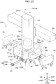
- the label suction part 11 has an air cylinder 11a having a vertically extending axis CL11 and fixed to the auxiliary part 4, a rod 11b that moves along the axis CL11 out of and into a bottom face of the air cylinder 11a, and a pad part 12 attached to a lower front end part of the rod 11b.
- the pad part 12 moves up and down for a predetermined stroke ( Fig. 5 : an arrow DRd).
- the pad part 12 has a base plate 13 of a flat shape whose left edge part is fixed to a front end of the rod 11b and a label pad part 14 attached to a right edge side of a bottom face of the base plate 13. Namely, the base plate 13 is attached to the rod 11b in such a way as to extend in a direction away from the transfer base rotation axis CL51.
- the label pad part 14 is a combination of two label pads 14a and 14b that are juxtaposed in the left-right direction in Fig. 5 .
- the label pads 14a and 14b are made of the same material and are formed in cuboid sponge bodies elongated in the front-rear direction in Fig. 5 (a front-back direction of the drawing).
- a material thereof is, for example, a chloroprene rubber sponge body. Accordingly, the label pads 14a and 14b have elasticity at least in the up-down direction.
- Figure 6 is a bottom view of the pad part 12.
- the label pads 14a and 14b have a plurality of vertically passing air holes 14h.
- the air holes 14h are arranged in three zigzag lines that are substantially evenly dispersed over each of bottom faces 14a1 and 14b1 of the label pads 14a and 14b.
- the air holes 14h are connected to hoses 15a and 15b that are extended from a top face of the base plate 13 and are passed through the base plate 13 to the label pads 14a and 14b, respectively.
- the hoses 15a and 15b are connected to a pump 772 for generating a negative pressure.
- the compressed air switch part 76 controls operation of the pumps 771 and 772.
- the compressed air switch part 76 is controlled by the compressed air control part 54b, to selectively execute operation of the pump 771 to suck air from the product suction pad part 5c, or operation of the pump 772 to suck air from the label pad part 14 of the label suction part 11, or operation of the both.
- the compressed air switch part 76 controls to operate the pump 772 so that a negative pressure is applied to the label pad part 14 of the label suction part 11, the air holes 14h of the bottom faces 14a1 and 14b1 of the label pads 14a and 14b draw air (arrows DRe). With this, the bottom faces 14a1 and 14b1 of the label pad part 14 are able to suck the label 62a.
- the compressed air switch part 76 controls to apply a negative pressure to the product suction pad parts 5c of the suction units 5, the suction cup parts 5c1 draw air. With this, the product suction pad parts 5c are able to suck the product WP.
- the bottom face 14a1 of the label pad 14a is flat and the size thereof is, for example, 70 (mm) ⁇ 22 (mm).
- the label pad 14a and the label pad 14b that is the same as the label pad 14a are juxtaposed with a proper gap Va between them, to form the label pad part 14 usable to suck a rectangular label of 60 (mm) square.
- Fig. 6 an outer shape of the label 62a sucked by the label pad part 14 is depicted with a chain line.
- the label pads 14a and 14b are each a cuboid and have suction faces, i.e., the flat bottom faces 14a1 and 14b1. With this, the label 62a sucked by the label pad part 14 is never centrally raised or is never deformed when sucked.
- the air drawing air holes 14h formed in the bottom faces 14a1 and 14b1 have a relatively small diameter and are substantially evenly distributed. With this, suction force to suck the label 62a is never biased depending on locations over the bottom faces 14a1 and 14b1 and never causes the problem of, for example, dropping the label 62a after suction.
- the product transfer apparatus 52 of the above-mentioned configuration is able to suck the product WP with the product suction pad parts 5c of the suction units 5 and is able to move the sucked product WP with the TK unit 51 to an optional position in an optional orientation within the movable range thereof.
- the label suction part 11 the label 62a that is pushed out of the printer 62 and exposed can be sucked and the sucked label 62a can be pasted with the TK unit 51 on a top face WPb of the product WP, which is placed on the work pallet 31, at an optional position in an optional orientation within the movable range of the TK unit 51.
- the TK unit 51 is a device for transferring the product WP and is a label pasting device for pasting the label 62a on the product WP.
- the product transfer operation is a combination of series processes including a label pasting process of pasting the label 62a at a required position on the product WP placed on the work pallet 31 and a product transferring process of transferring the product WP on which the label 62a is pasted to the transfer table 52b.
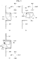
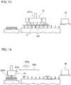
- Figures 7 to 14 are schematic side views explaining the product transfer operation including the label pasting process and product transferring process. The operation explained below is controlled by the control device 54. In Fig. 7 , an operation start basic state is illustrated.
- the product WP and skeleton WS i.e., a remainder that have been cut from a plate material, i.e., a raw material by, for example, laser processing in a preceding process.
- the TK unit 51 is at a raised position and the product suction part 51a is just above the product WP.
- the air cylinder 11a (refer to Fig. 5 ) of the label suction part 11 is in a state that the rod 11b is pulled therein.
- the bottom faces 14a1 and 14b1 of the label pad part 14 are at a position upwardly separated by a distance Hb from a suction height HR of the suction cup parts 5c1 of the suction units 5.
- an up-down-direction position (height) of the label 62a printed and pushed out of a casing is above the pass line PL and is upwardly spaced by a distance Ha from the top face WPb of the product WP.
- control device 54 horizontally moves (an arrow DRf) the TK unit 51 from the basic state while keeping the raised position and positions the label suction part 11 above the label 62a pushed out of the printer 62.
- the air cylinder 11a (refer to Fig. 5 ) of the label suction part 11 is operated, and as illustrated in Fig. 9 , the pad part 12 including the label pad part 14 is lowered (an arrow DRg).
- the compressed air switch part 76 (refer to Figs. 2 and 5 ) connects a negative pressure path to the label pad part 14 so that air suction can be carried out by the label suction part 11.
- a height of the TK unit 51 in the basic state is set such that, when the pad part 12 is lowered to a lowest position of the up-down movable range, the bottom faces 14a1 and 14b1 of the label pad part 14 are at a position to contact with or in the vicinity of the label 62a. This position of the bottom faces 14a1 and 14b1 is lower by a distance Hc than the suction height HR of the suction cup parts 5c1.
- the bottom faces 14a1 and 14b1 of the label pad part 14 are lowered to cross the position of the suction height HR of the suction cup parts 5c1 from above to below and are brought into contact with or in the vicinity of a top face of the label 62a.
- the label 62a drawn by the label pad part 14 is at a position higher by a distance Ha than the top face of the product WP.
- the TK unit 51 is horizontally moved without changing the height, to move the label 62a to above a pasting position of the product WP (refer to an arrow DRh of Fig. 10 ).
- the printer 62 operates in harmony with the horizontal movement of the TK unit 51, and just before the start of the horizontal movement, cuts a rear end of the label 62a sucked by the label pad part 14 with a built-in cutter (not illustrated).
- the control device 54 After moving the label 62a sucked by the label pad part 14 to above the pasting position of the product WP, the control device 54 lowers, as illustrated in Fig. 11 , the TK unit 51 by a predetermined distance Hd (an arrow DRj).
- the control device 54 if required, before or during the lowering of the TK unit 51, causes the TK rotation drive part 74 to rotate the TK unit 51 so that the label 62a is oriented in a predetermined direction.
- the predetermined distance Hd must be equal to or greater than the distance Ha. Setting the distance Hd to be greater than the distance Ha results in compressing the label pad part 14, and with its resilient repulsive force, pressing the label 62a to the top face WPb of the product WP, and therefore, is preferable.
- the label pads 14a and 14b are formed from, as already mentioned, elastic sponges. Due to this, the resilient repulsive force generated by compressing the label pad part 14 presses the sucked label 62a to the top face WPb of the product WP through the whole of the bottom faces 14a1 and 14b1. As a result, the label 62a causes no partial lift and is entirely surely pasted to the surface of the product WP, thereby stabilizing and realizing a high pasting quality.
- the compressed air control part 54b after the TK unit 51 is lowered and the label 62a is brought into contact with the product WP, closes the negative pressure path connected to the label pad part 14, to stop the suction through the air holes 14h.
- the control device 54 After pasting the label 62a, operates the air cylinder 11a while maintaining the height position of the TK unit 51, to raise the label suction part 11 (an arrow DRk). Up to here is the label pasting process.
- control device 54 After raising the label suction part 11 to complete the label pasting process, the control device 54 horizontally moves the TK unit 51 to above a suction location (usually, a center) of the product WP, and thereafter, lowers the same (refer to an arrow DRm of Fig. 13 ).
- control device 54 moves the TK unit 51 to above a position set as the suction position of the product WP, operates, if required, the TK rotation drive part 74 to establish a predetermined rotated state, and thereafter, lowers the same.
- the compressed air control part 54b activates the pump 771 connected to the product suction pad parts 5c, to start air suction by the suction cup parts 5c1. And, on the completion of the descending of the TK unit 51, the product suction pad parts 5c suck the product WP.
- the control device 54 After sucking the product WP, the control device 54 raises the TK unit 51 and horizontally moves the same to above the product stack WPT formed on the transfer table 52b ( Fig. 14 : an arrow DRn). If required, the TK unit 51 is rotated to a predetermined state ( Fig. 14 : an arrow DRp).
- control device 54 lowers the TK unit 51 and places the carried product WP on the product stack WPT. Thereafter, the compressed air control part 54b stops the pump 771 to stop air suction by the suction cup parts 5c1, thereby releasing the product WP.
- the control device 54 After releasing the product WP, the control device 54 returns the TK unit 51 to the basic state.
- a pasting position and pasting state (orientation) of the label 62a on the top face WPb of the product WP are optional.
- Figure 15 is a view illustrating pasted examples of the label 62a on the product WP and skeleton WS, i.e., a remainder that are placed on the work pallet 31.
- Fig. 15 as the product WP, two products WP1 and WP2 having different shapes are illustrated.
- the product transfer apparatus 52 is able to paste the label 62a on a predetermined part of the top face WPb of the product WP.
- the predetermined part is a part above which the label suction part 11 can be positioned by the horizontal movement and rotation of the TK unit 51.
- the product transfer apparatus 52 is capable of achieving (C) pasting the label 62a on the product WP1, which has a contour line WP1a slanted in the left-right direction on a horizontal plane, in a slanted orientation along the contour line WP1a.
- the product transfer apparatus 52 can paste the label 62a in an optional state at an optional position on the surface of the transferring product WP and can transfer the product WP on which the label 62a is pasted to a predetermined position.
- the product transfer apparatus 52 has, on the TK unit 51, the product suction part 51a, i.e., the transfer base for sucking the product WP and the label suction part 11 having an up-down function of ascending and descending independently of the product suction part 51a.
- the product suction part 51a i.e., the transfer base for sucking the product WP and the label suction part 11 having an up-down function of ascending and descending independently of the product suction part 51a.
- the pasting of the label 62a on the product WP can be carried out at an optional position and orientation without limitation by the horizontal movement and rotation of the TK unit 51, thereby stably maintaining a high-level pasting quality.
- the label suction part 11 has the flat label pads 14a and 14b that are not like suction cups but are like cuboids with label sucking flat faces.
- the label 62a is sucked by the label pads 14a and 14b without largely deformed, so that the pasting never causes problems such as wrinkles.
- the label suction part 11 can stand by at a position higher than the suction height HR at which the product suction part 51a sucks the product WP and can suck, keep, and paste a label at a position lower than the suction height HR, the up-down stroke of the air cylinder 11a and the most raised position and most lowered position of the label pad part 14 within the up-down stroke are set.
- the TK unit 51 as a whole can horizontally move to carry out the product suction operation without influenced by the label suction part 11. Accordingly, even if the label pasting operation is included in the product transferring operation, a label pasting time will be short to prevent the lowering of a product transfer efficiency of the product transfer apparatus 52.
- the label suction part 11 is provided for, as also illustrated in Fig. 16 , the auxiliary part 4 (or auxiliary part 3) extending sideward from the base part 2 of the TK unit 51.
- a distance L12 between the transfer base rotation axis CL51 that is a horizontal-direction center of the TK unit 51 and the center axis CL12 of the pad part 12 is elongated by an extended portion of the auxiliary part 4 compared to a case of arranging the label suction part 11 on the base part 2.
- a moving distance of the TK unit 51 to suck the label 62a can further be reduced by a reciprocation portion of the extension of the auxiliary part 4, thereby shortening a label pasting operation time and improving a working efficiency.
- the label suction part 11 is in accordance with the present invention modified to a rotation part 111 serving as a label suction part capable of rotating a rod 11b supporting the pad part 12.
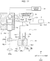
- the rotation part 111 will be explained with reference to Fig. 17 .
- the rotation part 111 has a motor 11c1 that is fixed to the auxiliary part 4 in a state that an output shaft 11c2 is downwardly oriented.
- the motor 11c1 is a motor such as a step motor whose rotation angle is controllable.
- a holder 11c3 At a front end of the output shaft 11c2 of the motor 11c1, there is arranged a holder 11c3 to which an upper part of the air cylinder 11a is fixed. Operation of the motor 11c1 is controlled by the control device 54.
- the orientation of the label 62a sucked by the label pad part 14 can optionally be changed without turning the TK unit 51 around the transfer base rotation axis CL51.
- installing the rotation part 111 enables the label 62a to be pasted on the product WP in an optional orientation without turning the TK unit 51.
- control device 54 executes the rotation of the motor 11c1 only when the rod 11b is positioned at the lowermost end or at the lower end side not interfering with the suction units 5.
- control device 54 when lifting the rod 11b, turns and orients the base plate 13 in a direction in which the base plate 13 extends away from the transfer base rotation axis CL51 not to interfere with the suction units 5, and then, lifts the rod 11b.
- the base plate 13 may be lengthy so that, when the label pad part 14 is turned, it is positioned at a center position of the base part 2 or at a position crossing the transfer base rotation axis CL51.
- Figure 18(a) is a partial plan view illustrating a skeleton WS and product WP placed on the work pallet 31 and Figs. 18(b) to (e) are enlarged views of a part A of Fig. 18(a) , i.e., a protruding corner part of the product WP.
- Figure 18(b) illustrates a case that the label 62a is pasted when the label pad part 14 is at a base position as illustrated in Fig. 17 where the label pad part 14 is on the right side of the label suction rotation axis CL11.
- printed characters "AM" on the label 62a are erect when seen from the right of the product WP.
- Figures 18(c) to (e) illustrate cases that the motor 11c1 is clockwise rotated in a top view by 90 degree, 180 degree, and 270 degrees, respectively, and the label 62a is pasted.
- the label 62a is oriented such that the printed characters "AM" are erect when seen from the front, left, and rear, respectively, of the product WP.
- the TK unit 51 in the case of pasting the label 62a to the same position in different orientations, the TK unit 51 must horizontally be moved according to an eccentric distance between the label suction rotation axis CL11 and the center axis CL12.
- the moving distance is small compared to the whole dimensions of the TK unit 51 and no rotation is involved in the movement, so that there is substantially no influence on a working efficiency.
- the pad part 12 of the label suction part 11 is preferable to be replaceable with respect to the rod 11b. This makes it possible to use the label pad part 14 having a size and shape optimized for the size and shape of the label 62a, thereby realizing a surer pasting operation and a higher pasting quality.
- the label pads 14a and 14b are not limited to cuboids if the bottom faces 14a1 and 14b1 are flat.
- the label pads 14a and 14b may have a truncated conical shape with a flat bottom face through which air holes are formed.
- the number of the air holes is not limited and is preferably plural.
- the TK unit 51 may be provided with a plurality of label suction parts 11.
- the printer 62 is configured to sequentially push out labels 62a3 and 62a4 corresponding to two products WP1 and WP2, and after the two label suction parts 11 suck the labels 62a3 and 62a4, respectively, a pasting operation to the products WP1 and WP2 is conducted.
- the label 62a is modifiable to a label 621a illustrated in Fig. 19(a).
- Figure 19(a) is a view seen from a bottom face (adhesive face) of the label 621a.
- a face with an adhesive layer that becomes a bottom face when discharged has a pair of edge parts in a width direction (a direction orthogonal to a discharge direction indicated with an arrow), the edge parts extending in the discharge direction to form non-adhesive parts 621b having no adhesive layers.
- the label 621a has, on the bottom face thereof, an adhesive part 621c in a hatched widthwise center portion and the pair of non-adhesive parts 621b that widthwise sandwich the adhesive part 621c.
- the printer 62 is equipped with, when using the label 621a, a pair of support tools 62b at positions corresponding to the non-adhesive parts 621b of the discharged label 621a, to support from below a horizontal state of the label 621a.
- the label 621a discharged without a release paper to a predetermined protrusion length is substantially horizontally supported with the pair of support tools 62b. Accordingly, there is no need of blowing air from below to maintain the horizontal state. Namely, a standby state until suction is stabilized.
- the label 62a for the printer 62 is not limited to the above-mentioned half-cut one in which a release paper is left from a roll.
- the label 62a may be, for example, one that is in a roll together with a release paper when printed.
- the printer 62 is provided with a built-in cutter, and when the label pad part 14 conducts suction and transfer, the label is separated from the release paper and is cut and separated with the built-in cutter of the printer 62.
- the product WP is not limited to one cut out of a plate-like raw material.
- the product means a plate-like member without regard to a preceding process or a processing type.
- the laser processing system STA is one that replaces the TK unit 51 with a TK unit 51A and an external configuration thereof is substantially the same as the laser processing system ST illustrated in Fig. 1 .
- marks 51A, 52A, and STA are added with parentheses.
- the TK unit 51A compared to the TK unit 51, deletes the label suction part 11 provided for the auxiliary part 4 and arranges a label suction part 21 on a base part 2A.
- the CPU 54d in the control device 54 has a rotation cylinder control part 54a for controlling operation of a rotation cylinder 211 (refer to Fig. 21 ) provided for the label suction part 21.
- the laser processing system ST of the Embodiment 1 and the laser processing system STA of the Embodiment 2 have the same configuration and executable operation except for the label suction part 11 and label suction part 21.
- the label suction part 21 arranged on the base part 2A will be explained with reference to Figs. 20 to 24 .
- Figure 20 is a perspective view of the TK unit 51A
- Fig. 21 a perspective view explaining operation of the label suction part 21
- Figs. 22 and 23 are a functional block diagram of the laser processing system STA as a whole, explaining operational control of the label suction part 21 and a block diagram related to the label suction part 21.
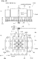
- Figure 24 (a) is a front view of a product suction part 51aA provided for the TK unit 51A and Fig. 24(b) a bottom view of the product suction part 51aA.
- the TK unit 51A has a TK up-down drive part 73A, a body part 1A, and the product suction part 51aA as a transfer base.
- the TK up-down drive part 73A has a servomotor (not illustrated) and is installed on the movable frame 52j.
- the body part 1A is supported to move up and down relative to the movable frame 52j with the servomotor of the TK up-down drive part 73A serving as a drive source.
- the product suction part 51aA is attached to a lower part of the body part 1A.
- the product suction part 51aA rotates (refer to an arrow DR1A), by operation of a TK rotation drive part 74A, with respect to the body part 1A around a transfer base rotation axis CL51A extending vertically.
- a rotation range is, for example, 180 degrees in each of clockwise and counterclockwise directions, i.e., 360 degrees in total from a state illustrated in Fig. 20 .
- the product suction part 51aA i.e., the transfer base is provided with a base part 2A and a pair of auxiliary parts 3A and 4A.
- the transfer base rotation axis CL51A is set to pass through a center position of the product suction part 51aA.
- the base part 2A is formed substantially in a hexahedral shape.
- auxiliary parts 3A and 4A are supported at front ends of support arm parts 3aA and 4aA that move into and out of the left and right of the base part 2A by operation of auxiliary arm drive parts 783A and 784A, respectively.
- the auxiliary parts 3A and 4A move between base positions closely attached to the base part 2A and extended positions protruding leftward and rightward (refer to arrows DRc).
- auxiliary parts 3A and 4A horizontally move toward and away from the transfer base rotation axis CL51A.
- auxiliary parts 3A and 4A at the base positions are depicted with continuous lines and the auxiliary parts 3A and 4A at the extended positions with chain lines.
- a plurality of suction units 5 that are the same as those of the Embodiment 1 are arranged along vertical axes.
- suction units 5 Employed as the suction units 5 are suction units 5d and suction units 5e that have stronger suction force than the suction units 5d.
- a plurality of the suction units 5e of stronger suction force are arranged in a dense zigzag array.
- a plurality of the suction units 5d having lower suction force than the suction units 5e are arranged in a zigzag array coarser than that of the suction units 5e.
- a front-rear-direction arrangement interval D5 (refer to Fig. 24(b) ) of the suction units 5d is set to allow a straight arm 212 to enter without interfering with the suction units 5d.
- each suction unit 5 is provided with a product suction pad part 5c. As illustrated in Figs. 22 and 23 , the product suction pad parts 5c are connected to the pump 771 for generating a negative pressure and operation of the pump 771 is controlled by the compressed air switch part 76.
- a rubber suction cup part 5c1 formed like the peripheral face of a truncated cone.
- the inside of the suction cup parts 5c1 can be set to a negative pressure to suck a flat plate member such as the product WP. Operation of the pump 771 is directly controlled by the compressed air switch part 76 and the compressed air switch part 76 is controlled by the control device 54.
- the label suction part 21 has a rotation cylinder 211 having a body part 211a and rod 211b, the arm 212, and a pad part 22.
- the body part 211a is fixed to the base part 2A in a state that a rotation axis CL21 is in parallel with the transfer base ration axis CL51A.
- the rod 211b moves up and down along the rotation axis CL21 for a predetermined stroke and rotates in an angular range of 180 degrees.
- the arm 212 is attached through a connection holder 213.
- the arm 212 is attached to the rod 211b in a state to extend in a direction orthogonal to the rotation axis CL21.
- the arm 212 is straightly formed to extend in a diameter direction with the rotation axis CL21 being a center. At a front end part of the arm 212, there is attached a pad part 22.
- the pad part 22 is configured similar to the pad part 12 of the Embodiment 1.
- the pad part 22 has a label pad part 23 that is a combination of label pads 23a and 23b.
- the label pads 23a and 23b are a group of the same material.
- each of them is formed as a cuboid sponge body elongating in the left-right direction.
- the material thereof is, for example, a chloroprene rubber sponge body.
- the label pads 23a and 23b have elasticity at least in the up-down direction.
- the label pads 23a and 23b have a plurality of vertically passing air holes (not illustrated) and the air holes are connected to, as illustrated in Fig. 23 , hoses 23c and 23d passed through the arm 212 and pulled out of a top face of the arm 212. In Fig. 23 , the hoses 23c and 23d are connected to the pump 772 for generating a negative pressure.
- the compressed air switch part 76 executes operation control under the control of the control device 54 with respect to the pumps 771 and 772 such that air suction is carried out by the product suction pad parts 5c of the suction units 5, or by the label pad part 23 of the label suction part 21, or by the both.
- the compressed air switch part 76 Under the control of the compressed air switch part 76, if the pump 772 is operated to apply a negative pressure to the label pad part 23 of the label suction part 21, the air holes (not illustrated) of the respective bottom faces of the label pads 23a and 23b draw air. With this, the bottom faces of the label pad part 23 can suck the label 62a.
- the suction cup parts 5c1 draw air. With this, the product suction pad parts 5c can suck the product WP.
- the arm 212 having at the front end thereof the label pad part 23 rotates, by operation of the rotation cylinder 211, at a rotation angle of 180 degrees.
- the arm 212 illustrated in Fig. 20 is at a right end position seen from the top of the rotation angle range.
- the rotation cylinder 211 incorporates, for example, a servomotor and operates under the control of the control device 54. More precisely, as illustrated in Fig. 23 , the rod 211b responds to a linear motion signal SG1 from the control device 54 to move along the rotation axis CL21 (up-down direction), and in response to a rotation signal SG2, turns around the rotation axis CL21 within a predetermined angular range. In connection with this, the rotation axis CL21 is called a label suction rotation axis CL21.
- the arm 212 connected to the rod 211b can at least take four positions from a first position PS1 to a fourth position PS4.
- Figures 24 to 27 illustrate states that the arm 212 are at the first position PS1 to the fourth position PS4, respectively.
- the arm 212 At the first position PS1 illustrated in Fig. 24 , the arm 212 is at a lowermost position in the up-down motion. In the rotatable range, it is at an endmost position in a counterclockwise direction in the bottom view of Fig. 24(b) . This endmost position is called a first rotation position of the arm 212.
- the arm 212 is positioned entirely lower than the suction units 5 in the up-down direction. Accordingly, even if the rod 211b turns to turn the arm 212, the arm 212 does not interfere with the suction units 5.
- the position of the label suction rotation axis CL21 of the arm 212 is in front of the transfer base rotation axis CL51A separated by a distance Da.
- the label pad part 23 is outside an external shape of the transfer base 51aA and a distance Db that is an arm length between the label suction rotation axis CL21 and a center axis CL22 of the label pad part 23 is equal to the distance Da.
- the arm 212 is, like the first position PS1, at the lowermost position in the up-down motion, and in the rotation range, is at a center position turned by 90 degrees from the first position PS1.
- the arm 212 is, like the first position PS1 and second position PS2, at the lowermost position in the up-down motion, and in the rotation range, is turned by 180 degrees from the first position SP1 and at an endmost position in a clockwise direction in the bottom view of Fig. 26(b) .
- the center axis CL22 of the label pad part 23 is at the same position as the transfer base rotation axis CL51A of the base part 2A. This position is called a second rotation position of the arm 212.
- the arm 212 is at the same position as the second position PS2 in the rotation range and at an uppermost position in the up-down motion. Also, the label pad part 23 is inside the outer shape of the transfer base 51aA.
- the bottom faces of the label pads 23a and 23b are positioned upper by a distance He than the bottom faces of the suction cup parts 5c1 of the suction units 5.
- the distance He is set such that, when the suction units 5 suck a work W, the label pads 23a and 23b may not be in contact with the work W without regard to deformation of the suction cup parts 5c1.
- the control device 54 sets the arm 212 of the TK unit 51A to the first position PS1 and turns the TK unit 51A so that the arm 212 extends in the left-right direction.
- the TK unit 51A is moved to the vicinity of the printer 62 and the pump 772 is activated to suck and obtain the label 62a.
- the label pad part 23 protrudes outside the base part 2A. Accordingly, a moved distance of the TK unit 51A is small to realize a good moving efficiency.
- the control device 54 sets the arm 212 to the third position PS3 and turns the TK unit 51A according to a pasting orientation of the label 62a. Also, a pasting position, i.e., a center position of the label 62a to be pasted to the product WP is brought to agree with a center position of the TK unit 51A, i.e., the transfer base rotation axis CL51A. Next, the TK unit 51A is lowered (an arrow DRj2), the pump 772 is stopped while the label 62a is pressed and pasted to the product WP, and the TK unit 51A is lifted.
- the control device 54 brings the arm 212 to the fourth position PS4 through the second position PS2. With this, the label pad part 23 stands by at an upper position without affecting the suction of the product WP.
- the control device 54 horizontally moves the TK unit 51A to above a suction position of the product WP, and then, lowers the same (an arrow DRmA). Next, the control device 54 activates the pump 771 to make the suction units 5 to suck and keep the product WP.
- the product WP is transferred to a predetermined location.
- the TK unit 51A is an apparatus for transferring the product WP, and also, a label pasting apparatus for pasting the label 62a on the product WP.
- Figure 31 is a schematic plan view explaining positional and attitudinal examples of the product suction part 51aA when the TK unit 51A takes and pastes the label 62a in the laser processing system STA.
- Figure 31 illustrates the work pallet 31, a work W placed on the work pallet 31, and the product suction part 51aA.
- a right upper part (P1) illustrates an example of obtaining the label 62a
- a left upper part (P2) a first label pasting example
- a left lower part (P3) a second label pasting example.
- external shapes of the base part 2A and auxiliary parts 3A and 4A are depicted with chain lines.
- the arm 212 is brought to the first position PS1 so that the label is obtained with the label suction part 21 positioned away from the base part 2A.
- the label 62a is obtainable with the position of the transfer base rotation axis CL51A, i.e., the center of the base part 2A kept within a range corresponding to the work pallet 31.
- the center of a pasting position of the label 62a agrees with the transfer base rotation axis CL51A of the base part 2A of the TK unit 51A. Accordingly, the label 62a to be pasted can optionally be oriented by turning the base part 2A.
- the label pasting orientation of the label 62a in the part (P2) is a 180-degree-turned orientation with respect to the orientation in which the label is obtained from the printer 62 and the label pasting orientation of the label 62a in the part (P3) is a 90-degree-counterclockwise-turned orientation with respect to the orientation in which the label is obtained from the printer 62.
- the laser processing system STA of the Embodiment 2 is not required to, when pasting the label 62a to the same position in a different orientation, horizontally move the TK unit 51A but is needed only to turn the base part 2A at the same position. Accordingly, a pasting operation in an optional orientation of the label 62a can be carried out at a high efficiency.
- the center position of the TK unit 51A is moved only within a range corresponding to the work pallet 31. Therefore, a moving time is short, and in this point also, the pasting work can be carried out at a high efficiency.
- the distance L12 between the position of the rotation axis CL51 at the center of the base part 2 and the center axis CL12 of the pad part 12 is not 0 (zero) but is variable depending on a movement of the auxiliary part 4 toward and away from the base part 2.
- the Embodiment 1 specifies, in a program controlling the operation of the TK unit 51, coordinates of two positions, i.e., a center position for sucking and keeping the product WP and a center position for pasting the label 62a, among which the coordinates of the pasting position of the label 62a must be specified by always reflecting a distance between the auxiliary part 4 and the base part 2.
- the TK unit 51A of the Embodiment 2 is 0 (zero) in the distance between the position of the transfer base rotation axis CL51A, i.e., the center of the base part 2A and the center axis CL22 of the pad part 22 and this distance is unchanged even if the auxiliary part 4A is moved toward or away from the base part 2A.
- the program can specify the coordinates of a center position for sucking and keeping the product WP and the coordinates of a center position for pasting the label 62a by making them agree with each other. This results in simplifying the program and reducing program errors.
- Embodiment 2 of the present invention is not limited to the above-mentioned configurations and sequences but is modifiable without departing from the scope of the present invention as defined by the appended claims.
- the arm 212 may be not straight.
- the suction units 5d among the suction units 5 on the base part 2A are densely arranged in a zigzag array so that the straight arm 212 at the fourth position PS4 is unable to be retracted between the suction units 5d.
- an arm 212A of unstraight shape is employable.
- the arm 212A is zigzagged as an example.
- the rotation cylinder 211 is not limited to one that is operated by a servomotor.
- it may be an air cylinder that linearly and rotationally move the rod 211b by air.
- Figure 33 is a view illustrating an air circuit example when the rotation cylinder 211 is an air cylinder.
- the laser processing system STA is provided with an air drive part 8 for driving the rotation cylinder 211.
- the air drive part 8 is constituted by including five-port-type solenoid valves 25 and 26, speed controllers 251, 252, 261, and 262, air paths AR1 and AR2 whose first ends are connected to the solenoid valve 25, and air paths AR3 and AR4 whose first ends are connected to the solenoid valve 26. Operation of the solenoid valves 25 and 26 is controlled by the rotation cylinder control part 54d.
- the air path AR1 has the speed controller 251 and a second end connected to an air chamber to lower the rod 211b by air supply.
- the air path AR2 has the speed controller 252 and a second end connected to an air chamber to lift the rod 211b by air supply.
- the air path AR3 has the speed controller 261 and a second end connected to an air chamber to turn the rod 211b in a counterclockwise direction (an arrow DRt1) in Fig. 33 by air supply.
- the air path AR4 has the speed controller 262 and a second end connected to an air chamber to turn the rod 211b in a clockwise direction (an arrow DRt2) in Fig. 33 by supplying air.
- the solenoid valve 25 selectively supplies air to one of the air paths AR1 and AR2. With this, the rod 211b moves up or down and is kept at a selected one of the end positions of an up-down stroke. Also, under the control of the rotation cylinder control part 54d, the solenoid valve 26 selectively supplies air to one of the air paths AR3 and AR4. With this, the rod 211b rotates and is kept at a selected one of the end positions in the rotation range.
- the first position PS1 and third position PS3 of the arm 212 is obtainable only by switching operation of the solenoid valves 25 and 26.
- the speed controllers 261 and 262 are adjusted to adjust air discharge speeds from the air chambers.
- air supply timing of the operation of the solenoid valve 26 is adjusted. With this adjustment, a pressure balance is established between the two air chambers contributing to the rotation so that the arm 212 is kept at the center position of the rotation range.
- the guide plate 24 has an open inclined part, which is formed at a lower part and is widened to serve as a guide, and a guide slit 241 extended upwardly.
- the guide roller 213b is attached to a front end of a roller bracket 213a, is engaged with the guide slit 241 substantially without a widthwise gap between them, and is movable up and down.
- the printer 62 may be a printer 62A illustrated in Fig. 34 .
- the printer 62A has, as members to receive the label 62a discharged from a discharge port 67, a base plate 65 and a label receiving plate 66.
- the base plate 65 has, in a central area, a seal frame part 65c made of, for example, rubber formed in an upwardly protruding frame and through holes (not illustrated) formed in the range of the seal frame part 65c.
- the label receiving plate 66 has a top face coating on which the label 62a is placed, and on a bottom face side, a plurality of small-diameter air holes 66c in a range surrounded by the seal frame part 65c when attached to the base plate 65.
- the label receiving plate 66 is attached to the base plate 65 with bolts 65b such that the bottom face thereof is closely attached to the seal frame part 65c. In this state, a space surrounded by the seal frame part 65c communicates with the outside only through the through holes of the base plate 65 and the plurality of air holes 66c of the label receiving plate 66.
- a non-adhesive layer 66a is formed by coating. This non-adhesive layer 66a has non-adhesiveness with respect to a contacting adhesive.
- the label 62a is simply placed on the label receiving plate 66 with an adhesive thereof not adhering to the label receiving plate 66. Accordingly, the label 62a placed on the label receiving plate 66 can easily be sucked and moved by the label pad part 23.
- the coating means a process of laminating, on a substrate, a carbide-based sprayed film and a silicon resin film one on another in this order, or a surface layer formed by such a process.
- the printer 62A discharges the label 62a
- the label 62a slides on the label receiving plate 66.
- air is supplied from the outside through the through holes of the base plate 65 into the seal frame part 65c. This air upwardly blows through the air holes 66c of the label receiving plate 66, to slightly raise the label 62a during the discharge.
- the product transfer apparatus 52A with the above-mentioned configuration sucks the product WP with the product suction pad parts 5c of the suction units 5 and moves the product WP by moving the TK unit 51 to an optional position.
- the product transfer apparatus 52A sucks and keeps, with the label suction part 21, the label 62a pushed and exposed out of the printer 62.
- the label 62a can be pasted to an optional position of the top face WPb of the product WP according to the horizontal, up/down, and rotation movements of the TK unit 51A and the up/down and rotation movements of the arm 212 of the label suction part 21.
- the product transfer apparatus 52A is easily able to paste the label 62a on the top face WPb in an optional orientation with the transfer base rotation axis CL51A of the TK unit 51A as a pasting center position.
- the label pad part 23 is at a lower center position of the base part 2A of the transfer base 51aA or a position crossing the transfer base rotation axis CL51A under the base part 2A.
- the transfer base rotation axis CL51A may be set not to pass the center position of the transfer base, even when a top-viewed outer shape of the transfer base 51aA is symmetrical.
- a position of the label pad part 23 on a plane at the second rotation position is set to a position crossing the transfer base rotation axis CL51A under the base part 2A.
- Embodiment 1 and Embodiment 2 may properly be combined within a possible scope as defined by the appended claims.
- a combination of one of the product transfer apparatuses 52 and 52A, one of the printers 62 and 62A, and the work pallet 31 may be called and handled as a product transfer system HST (refer to Fig. 1 ).
Landscapes
- Engineering & Computer Science (AREA)
- Mechanical Engineering (AREA)
- Labeling Devices (AREA)
Claims (9)
- Eine Produkttransfervorrichtung, umfassend:einen Produktsaugteil (5c) mit einem Saugnapfteil (5c1), der in der Lage ist, ein plattenförmiges Produkt anzusaugen; undeine Transferbasis (51a, 51aA), deren unterer Teil den Produktsaugteil (5c) aufweist, undein Etikettensaugteil (11, 21) mit einem Etikettenkissen (14a, 14b, 23a, 23b), das in der Lage ist, ein auf das Produkt zu klebendes Etikett (62a, 62a3, 62a4, 621a-621c) anzusaugen, dadurch gekennzeichnet, dass das Etikettensaugteil (11, 21) eine Aufwärts/Abwärts-Funktion zum Bewegen des Etikettenkissens (14a, 14b, 23a, 23b) nach oben und unten zwischen einer Position oberhalb und einer Position unterhalb der Position eines vorderen Endes des Saugnapfteils (5c1) umfasst; undein Drehteil (111, 211b) zum Drehen des Etikettensaugteils (11, 21) um eine Etikettensaugdrehachse (CL11, CL21), die sich in einer Aufwärts-Abwärts-Richtung erstreckt, wobeidas Etikettensaugteil (11, 21) einen Arm (13, 212) aufweist, der sich in einer diametralen Richtung von der Etikettensaugdrehachse erstreckt und an einem vorderen Ende das Etikettenkissen (14a, 14b, 23a, 23b) aufweist, und dass der Arm (13, 212) durch Betätigung des Drehteils (111, 211b) zwischen einer ersten Drehposition (PS1) außerhalb einer Außenform der Transferbasis (51a, 51aA) und einer zweiten Drehposition (PS2) innerhalb der Außenform der Transferbasis (51a, 51aA) gedreht wird.
- Die Produkttransfervorrichtung gemäß Anspruch 1, gekennzeichnet dadurch dass
das Etikettenkissen (14a, 14b, 23a, 23b) eine flache Unterseite (14a1, 14b1) hat und dass die Unterseite eine Saugfläche zum Saugen des Etiketts (62a) ist. - Die Produkttransfervorrichtung gemäß Anspruch 1 oder 2, gekennzeichnet dadurch dass,
in der zweiten Drehposition sich das Etikettenkissen (14a, 14b, 23a, 23b) unter einer mittleren Position der Transferbasis (51a, 51aA) befindet. - Die Produkttransfervorrichtung gemäß einem der Ansprüche 1 bis 3, gekennzeichnet durch:ein Auf-Ab-Antriebsteil (73, 73A), um die Transferbasis (51a, 51aA) auf und ab zu bewegen;ein Rotationsantriebsteil (74, 74A) zum Drehen der Transferbasis (51a, 51aA) um eine Transferbasis-Rotationsachse (CL51, CL51A), die sich in der Auf-Ab-Richtung erstreckt; undein horizontales Antriebsteil (72) zum horizontalen Bewegen der Transferbasis (51a, 51aA).
- Die Produkttransfervorrichtung gemäß Anspruch 4, gekennzeichnet dadurch dass:
die Transferbasis (51a, 51aA) ein Basisteil (2, 2A), das an einer die Rotationsachse der Transferbasis schneidenden Position angeordnet ist, und ein Hilfsteil (3, 4, 3A, 4A) umfasst, das den Etikettensaugteil (11, 21) aufweist und von dem Basisteil so getragen wird, dass es von der Rotationsachse der Transferbasis weg und zu ihr hin beweglich ist. - Die Produkttransfervorrichtung gemäß Anspruch 4, gekennzeichnet dadurch dass:der Transfersockel (51a, 51aA) das Etikettensaugteil (11, 21) aufweist und an einer Position angeordnet ist, die die Drehachse der Transferbasis schneidet; undin der zweiten Drehposition das Etikettenkissen (14a, 14b, 23a, 23b) so positioniert ist, dass es die Drehachse der Transferbasis schneidet.
- Produkttransfersystem mit einer Produkttransfervorrichtung gemäß Anspruch 1, wobei das Produkttransfersystem ferner umfasst:eine Arbeitspalette (31), die das plattenförmige Produkt trägt; undeinen Drucker (62), der das mit Informationen über das Produkt bedruckte Etikett (62a, 62a3, 62a4, 621a-621c) ausgibt.
- Das Produkttransfersystem gemäß Anspruch 7, des weiteren umfassend
ein Etikett (62a, 62a3, 62a4, 621a-621c), wobei das Etikett (62a, 62a3, 62a4, 621a-621c) auf einer Unterseite einen nichtklebenden Teil (621b) entlang eines jeden Paares von Kantenabschnitten in Breitenrichtung aufweist und dass der Drucker (62) ein Stützwerkzeug (62b) aufweist, um das Paar von nichtklebenden Teilen (621b) des ausgegebenen Etiketts (62a, 62a3, 62a4, 621a-621c) zu unterstützen. - Das Produkttransfersystem gemäß Anspruch 7, gekennzeichnet dadurch dass
der Drucker (62) eine Etikettenaufnahmeplatte (66) mit einer Vielzahl von Luftlöchern (66c) und einer nicht klebenden Schicht (66a) auf einer Oberseite aufweist, die durch Beschichtung gebildet wurde.
Applications Claiming Priority (3)
| Application Number | Priority Date | Filing Date | Title |
|---|---|---|---|
| JP2017215467 | 2017-11-08 | ||
| JP2018204607A JP6589035B2 (ja) | 2017-11-08 | 2018-10-31 | 製品搬送装置及び製品搬送システム |
| PCT/JP2018/041439 WO2019093407A1 (ja) | 2017-11-08 | 2018-11-08 | 製品搬送装置及び製品搬送システム |
Publications (3)
| Publication Number | Publication Date |
|---|---|
| EP3708508A1 EP3708508A1 (de) | 2020-09-16 |
| EP3708508A4 EP3708508A4 (de) | 2021-01-13 |
| EP3708508B1 true EP3708508B1 (de) | 2022-04-13 |
Family
ID=66438475
Family Applications (1)
| Application Number | Title | Priority Date | Filing Date |
|---|---|---|---|
| EP18875194.5A Active EP3708508B1 (de) | 2017-11-08 | 2018-11-08 | Produkttransfervorrichtung und produkttransfersystem |
Country Status (2)
| Country | Link |
|---|---|
| EP (1) | EP3708508B1 (de) |
| WO (1) | WO2019093407A1 (de) |
Families Citing this family (2)
| Publication number | Priority date | Publication date | Assignee | Title |
|---|---|---|---|---|
| JP7103517B2 (ja) * | 2019-06-06 | 2022-07-20 | 村田機械株式会社 | 搬送装置 |
| CN112478353B (zh) * | 2020-12-09 | 2024-10-22 | 中国工程物理研究院机械制造工艺研究所 | 一种非卷筒式不干胶标签自动贴标装置 |
Family Cites Families (14)
| Publication number | Priority date | Publication date | Assignee | Title |
|---|---|---|---|---|
| JPS6021155Y2 (ja) * | 1982-09-13 | 1985-06-24 | 株式会社平安鉄工所 | 木工機械の板材方向転換装置 |
| DE3831392A1 (de) * | 1988-09-15 | 1990-03-29 | Fraunhofer Ges Forschung | Verfahren und vorrichtung zum aufbringen von klebeschildern auf einem werkstueck |
| JP3544554B2 (ja) * | 1993-07-28 | 2004-07-21 | 多摩川精機株式会社 | ラベル紙の搬出機構 |
| DE19545191A1 (de) * | 1995-12-04 | 1997-06-05 | Siemens Nixdorf Inf Syst | Vorrichtung zum Bereitstellen und Applizieren von Etiketten und Verfahren zum Betrieb dieser Vorrichtung |
| IT242885Y1 (it) * | 1997-10-20 | 2002-02-04 | Bolla Luigi Srl | Dispositivo di etichettatura da applicare su banchi per il taglio dilastre di vetro piano |
| JP2001183984A (ja) * | 1999-12-22 | 2001-07-06 | Sato Corp | 台紙なしラベル |
| JP2003170330A (ja) | 2001-12-07 | 2003-06-17 | Murata Mach Ltd | 板材搬送装置 |
| JP4355230B2 (ja) * | 2004-02-13 | 2009-10-28 | 中央精機株式会社 | 防錆フィルムの貼付方法およびフィルム貼付装置。 |
| JP2007137471A (ja) * | 2005-11-18 | 2007-06-07 | Kojo Seiko Kk | ラベル貼付機 |
| ITMI20070968A1 (it) * | 2007-05-11 | 2008-11-12 | Meccano System S R L | Apparecchiatura di carico/scarico in asservimento ad un centro di taglio di lastre. |
| JP5022851B2 (ja) * | 2007-09-29 | 2012-09-12 | 株式会社サトー知識財産研究所 | ラベル貼付システム |
| JP4778498B2 (ja) * | 2007-11-26 | 2011-09-21 | 日東電工株式会社 | ラベル貼付け方法およびラベル貼付け装置 |
| JP2017215467A (ja) | 2016-05-31 | 2017-12-07 | キヤノン株式会社 | 定着装置に用いるフィルム及びこのフィルムを備える定着装置 |
| DE102017112350B4 (de) | 2017-06-06 | 2024-10-17 | Dr. Ing. H.C. F. Porsche Aktiengesellschaft | Zylinderkopf für eine Verbrennungskraftmaschine, Verbrennungskraftmaschine und Verfahren zum Betreiben einer Verbrennungskraftmaschine |
-
2018
- 2018-11-08 WO PCT/JP2018/041439 patent/WO2019093407A1/ja not_active Ceased
- 2018-11-08 EP EP18875194.5A patent/EP3708508B1/de active Active
Also Published As
| Publication number | Publication date |
|---|---|
| EP3708508A1 (de) | 2020-09-16 |
| EP3708508A4 (de) | 2021-01-13 |
| WO2019093407A1 (ja) | 2019-05-16 |
Similar Documents
| Publication | Publication Date | Title |
|---|---|---|
| US11077978B2 (en) | Product transfer apparatus and product transfer system | |
| US8562784B2 (en) | Automatic spacers mounting system for field emission display and method of automatically mounting spacers | |
| JP4947146B2 (ja) | レーザ加工装置 | |
| EP3708508A1 (de) | Produkttransfervorrichtung und produkttransfersystem | |
| JP4388493B2 (ja) | ガラス基板用フイルムの貼付方法 | |
| KR20130058607A (ko) | 도포 장치 | |
| JP2004026569A (ja) | ガラス板の加工装置 | |
| CN102189057A (zh) | 液滴排出装置 | |
| CN101742897B (zh) | 电子部件的安装方法及电子部件安装装置 | |
| WO2007037005A1 (ja) | ワーク収納装置 | |
| JP6737649B2 (ja) | 塗布装置および塗布方法 | |
| JP2024507048A (ja) | 食用製品のための切断装置及び切断方法 | |
| JP5849459B2 (ja) | 処理装置及び処理方法 | |
| CN101862898A (zh) | 基板处理装置及对基板施加标记的方法 | |
| JP4283810B2 (ja) | 穿孔装置 | |
| JP2004172318A (ja) | ワークテーブル、ワーク搬送装置、液滴吐出装置、ワーク受け渡し方法、電気光学装置、電気光学装置の製造方法および電子機器 | |
| JP2020096063A (ja) | 基板搬送装置および塗布装置 | |
| KR101202455B1 (ko) | 코팅 영역의 기판 이송 유닛에 사용되는 이송 캐리어의 피딩 장치, 및 이를 구비한 기판 이송 유닛 및 코팅 장치 | |
| JP5028195B2 (ja) | 基板処理装置および基板処理方法 | |
| JP2002172441A (ja) | 板材加工システム | |
| JP7853372B2 (ja) | 基板処理装置 | |
| JP2008087792A (ja) | 空袋表面への表示付与方法および装置 | |
| WO2006003876A1 (ja) | 基板塗布装置 | |
| JPH1121762A (ja) | シート加工装置、衣服の製造方法、及び記憶媒体 | |
| JP2579835Y2 (ja) | シート状物の位置決め装置 |
Legal Events
| Date | Code | Title | Description |
|---|---|---|---|
| STAA | Information on the status of an ep patent application or granted ep patent |
Free format text: STATUS: THE INTERNATIONAL PUBLICATION HAS BEEN MADE |
|
| PUAI | Public reference made under article 153(3) epc to a published international application that has entered the european phase |
Free format text: ORIGINAL CODE: 0009012 |
|
| STAA | Information on the status of an ep patent application or granted ep patent |
Free format text: STATUS: REQUEST FOR EXAMINATION WAS MADE |
|
| 17P | Request for examination filed |
Effective date: 20200508 |
|
| AK | Designated contracting states |
Kind code of ref document: A1 Designated state(s): AL AT BE BG CH CY CZ DE DK EE ES FI FR GB GR HR HU IE IS IT LI LT LU LV MC MK MT NL NO PL PT RO RS SE SI SK SM TR |
|
| AX | Request for extension of the european patent |
Extension state: BA ME |
|
| A4 | Supplementary search report drawn up and despatched |
Effective date: 20201210 |
|
| RIC1 | Information provided on ipc code assigned before grant |
Ipc: B65C 9/26 20060101AFI20201207BHEP Ipc: B65C 9/36 20060101ALI20201207BHEP Ipc: B65C 1/02 20060101ALI20201207BHEP |
|
| DAV | Request for validation of the european patent (deleted) | ||
| DAX | Request for extension of the european patent (deleted) | ||
| RIC1 | Information provided on ipc code assigned before grant |
Ipc: B21D 43/10 20060101ALI20210928BHEP Ipc: B21D 43/11 20060101ALI20210928BHEP Ipc: B21D 43/18 20060101ALI20210928BHEP Ipc: B21D 43/28 20060101ALI20210928BHEP Ipc: B65G 47/91 20060101ALI20210928BHEP Ipc: B65C 1/02 20060101ALI20210928BHEP Ipc: B65C 9/36 20060101ALI20210928BHEP Ipc: B65C 9/26 20060101AFI20210928BHEP |
|
| GRAP | Despatch of communication of intention to grant a patent |
Free format text: ORIGINAL CODE: EPIDOSNIGR1 |
|
| STAA | Information on the status of an ep patent application or granted ep patent |
Free format text: STATUS: GRANT OF PATENT IS INTENDED |
|
| INTG | Intention to grant announced |
Effective date: 20211110 |
|
| GRAS | Grant fee paid |
Free format text: ORIGINAL CODE: EPIDOSNIGR3 |
|
| GRAA | (expected) grant |
Free format text: ORIGINAL CODE: 0009210 |
|
| STAA | Information on the status of an ep patent application or granted ep patent |
Free format text: STATUS: THE PATENT HAS BEEN GRANTED |
|
| AK | Designated contracting states |
Kind code of ref document: B1 Designated state(s): AL AT BE BG CH CY CZ DE DK EE ES FI FR GB GR HR HU IE IS IT LI LT LU LV MC MK MT NL NO PL PT RO RS SE SI SK SM TR |
|
| REG | Reference to a national code |
Ref country code: GB Ref legal event code: FG4D |
|
| REG | Reference to a national code |
Ref country code: CH Ref legal event code: EP |
|
| REG | Reference to a national code |
Ref country code: DE Ref legal event code: R096 Ref document number: 602018033950 Country of ref document: DE |
|
| REG | Reference to a national code |
Ref country code: IE Ref legal event code: FG4D |
|
| REG | Reference to a national code |
Ref country code: AT Ref legal event code: REF Ref document number: 1483252 Country of ref document: AT Kind code of ref document: T Effective date: 20220515 |
|
| REG | Reference to a national code |
Ref country code: LT Ref legal event code: MG9D |
|
| REG | Reference to a national code |
Ref country code: NL Ref legal event code: MP Effective date: 20220413 |
|
| REG | Reference to a national code |
Ref country code: AT Ref legal event code: MK05 Ref document number: 1483252 Country of ref document: AT Kind code of ref document: T Effective date: 20220413 |
|
| PG25 | Lapsed in a contracting state [announced via postgrant information from national office to epo] |
Ref country code: NL Free format text: LAPSE BECAUSE OF FAILURE TO SUBMIT A TRANSLATION OF THE DESCRIPTION OR TO PAY THE FEE WITHIN THE PRESCRIBED TIME-LIMIT Effective date: 20220413 |
|
| PG25 | Lapsed in a contracting state [announced via postgrant information from national office to epo] |
Ref country code: SE Free format text: LAPSE BECAUSE OF FAILURE TO SUBMIT A TRANSLATION OF THE DESCRIPTION OR TO PAY THE FEE WITHIN THE PRESCRIBED TIME-LIMIT Effective date: 20220413 Ref country code: PT Free format text: LAPSE BECAUSE OF FAILURE TO SUBMIT A TRANSLATION OF THE DESCRIPTION OR TO PAY THE FEE WITHIN THE PRESCRIBED TIME-LIMIT Effective date: 20220816 Ref country code: NO Free format text: LAPSE BECAUSE OF FAILURE TO SUBMIT A TRANSLATION OF THE DESCRIPTION OR TO PAY THE FEE WITHIN THE PRESCRIBED TIME-LIMIT Effective date: 20220713 Ref country code: LT Free format text: LAPSE BECAUSE OF FAILURE TO SUBMIT A TRANSLATION OF THE DESCRIPTION OR TO PAY THE FEE WITHIN THE PRESCRIBED TIME-LIMIT Effective date: 20220413 Ref country code: HR Free format text: LAPSE BECAUSE OF FAILURE TO SUBMIT A TRANSLATION OF THE DESCRIPTION OR TO PAY THE FEE WITHIN THE PRESCRIBED TIME-LIMIT Effective date: 20220413 Ref country code: GR Free format text: LAPSE BECAUSE OF FAILURE TO SUBMIT A TRANSLATION OF THE DESCRIPTION OR TO PAY THE FEE WITHIN THE PRESCRIBED TIME-LIMIT Effective date: 20220714 Ref country code: FI Free format text: LAPSE BECAUSE OF FAILURE TO SUBMIT A TRANSLATION OF THE DESCRIPTION OR TO PAY THE FEE WITHIN THE PRESCRIBED TIME-LIMIT Effective date: 20220413 Ref country code: ES Free format text: LAPSE BECAUSE OF FAILURE TO SUBMIT A TRANSLATION OF THE DESCRIPTION OR TO PAY THE FEE WITHIN THE PRESCRIBED TIME-LIMIT Effective date: 20220413 Ref country code: BG Free format text: LAPSE BECAUSE OF FAILURE TO SUBMIT A TRANSLATION OF THE DESCRIPTION OR TO PAY THE FEE WITHIN THE PRESCRIBED TIME-LIMIT Effective date: 20220713 Ref country code: AT Free format text: LAPSE BECAUSE OF FAILURE TO SUBMIT A TRANSLATION OF THE DESCRIPTION OR TO PAY THE FEE WITHIN THE PRESCRIBED TIME-LIMIT Effective date: 20220413 |
|
| PG25 | Lapsed in a contracting state [announced via postgrant information from national office to epo] |
Ref country code: RS Free format text: LAPSE BECAUSE OF FAILURE TO SUBMIT A TRANSLATION OF THE DESCRIPTION OR TO PAY THE FEE WITHIN THE PRESCRIBED TIME-LIMIT Effective date: 20220413 Ref country code: PL Free format text: LAPSE BECAUSE OF FAILURE TO SUBMIT A TRANSLATION OF THE DESCRIPTION OR TO PAY THE FEE WITHIN THE PRESCRIBED TIME-LIMIT Effective date: 20220413 Ref country code: LV Free format text: LAPSE BECAUSE OF FAILURE TO SUBMIT A TRANSLATION OF THE DESCRIPTION OR TO PAY THE FEE WITHIN THE PRESCRIBED TIME-LIMIT Effective date: 20220413 Ref country code: IS Free format text: LAPSE BECAUSE OF FAILURE TO SUBMIT A TRANSLATION OF THE DESCRIPTION OR TO PAY THE FEE WITHIN THE PRESCRIBED TIME-LIMIT Effective date: 20220813 |
|
| REG | Reference to a national code |
Ref country code: DE Ref legal event code: R097 Ref document number: 602018033950 Country of ref document: DE |
|
| PG25 | Lapsed in a contracting state [announced via postgrant information from national office to epo] |
Ref country code: SM Free format text: LAPSE BECAUSE OF FAILURE TO SUBMIT A TRANSLATION OF THE DESCRIPTION OR TO PAY THE FEE WITHIN THE PRESCRIBED TIME-LIMIT Effective date: 20220413 Ref country code: SK Free format text: LAPSE BECAUSE OF FAILURE TO SUBMIT A TRANSLATION OF THE DESCRIPTION OR TO PAY THE FEE WITHIN THE PRESCRIBED TIME-LIMIT Effective date: 20220413 Ref country code: RO Free format text: LAPSE BECAUSE OF FAILURE TO SUBMIT A TRANSLATION OF THE DESCRIPTION OR TO PAY THE FEE WITHIN THE PRESCRIBED TIME-LIMIT Effective date: 20220413 Ref country code: EE Free format text: LAPSE BECAUSE OF FAILURE TO SUBMIT A TRANSLATION OF THE DESCRIPTION OR TO PAY THE FEE WITHIN THE PRESCRIBED TIME-LIMIT Effective date: 20220413 Ref country code: DK Free format text: LAPSE BECAUSE OF FAILURE TO SUBMIT A TRANSLATION OF THE DESCRIPTION OR TO PAY THE FEE WITHIN THE PRESCRIBED TIME-LIMIT Effective date: 20220413 Ref country code: CZ Free format text: LAPSE BECAUSE OF FAILURE TO SUBMIT A TRANSLATION OF THE DESCRIPTION OR TO PAY THE FEE WITHIN THE PRESCRIBED TIME-LIMIT Effective date: 20220413 |
|
| PLBE | No opposition filed within time limit |
Free format text: ORIGINAL CODE: 0009261 |
|
| STAA | Information on the status of an ep patent application or granted ep patent |
Free format text: STATUS: NO OPPOSITION FILED WITHIN TIME LIMIT |
|
| 26N | No opposition filed |
Effective date: 20230116 |
|
| PG25 | Lapsed in a contracting state [announced via postgrant information from national office to epo] |
Ref country code: AL Free format text: LAPSE BECAUSE OF FAILURE TO SUBMIT A TRANSLATION OF THE DESCRIPTION OR TO PAY THE FEE WITHIN THE PRESCRIBED TIME-LIMIT Effective date: 20220413 |
|
| PG25 | Lapsed in a contracting state [announced via postgrant information from national office to epo] |
Ref country code: SI Free format text: LAPSE BECAUSE OF FAILURE TO SUBMIT A TRANSLATION OF THE DESCRIPTION OR TO PAY THE FEE WITHIN THE PRESCRIBED TIME-LIMIT Effective date: 20220413 |
|
| P01 | Opt-out of the competence of the unified patent court (upc) registered |
Effective date: 20230428 |
|
| PG25 | Lapsed in a contracting state [announced via postgrant information from national office to epo] |
Ref country code: MC Free format text: LAPSE BECAUSE OF FAILURE TO SUBMIT A TRANSLATION OF THE DESCRIPTION OR TO PAY THE FEE WITHIN THE PRESCRIBED TIME-LIMIT Effective date: 20220413 |
|
| REG | Reference to a national code |
Ref country code: CH Ref legal event code: PL |
|
| GBPC | Gb: european patent ceased through non-payment of renewal fee |
Effective date: 20221108 |
|
| REG | Reference to a national code |
Ref country code: BE Ref legal event code: MM Effective date: 20221130 |
|
| PG25 | Lapsed in a contracting state [announced via postgrant information from national office to epo] |
Ref country code: LI Free format text: LAPSE BECAUSE OF NON-PAYMENT OF DUE FEES Effective date: 20221130 Ref country code: CH Free format text: LAPSE BECAUSE OF NON-PAYMENT OF DUE FEES Effective date: 20221130 |
|
| PG25 | Lapsed in a contracting state [announced via postgrant information from national office to epo] |
Ref country code: LU Free format text: LAPSE BECAUSE OF NON-PAYMENT OF DUE FEES Effective date: 20221108 |
|
| PG25 | Lapsed in a contracting state [announced via postgrant information from national office to epo] |
Ref country code: IE Free format text: LAPSE BECAUSE OF NON-PAYMENT OF DUE FEES Effective date: 20221108 Ref country code: GB Free format text: LAPSE BECAUSE OF NON-PAYMENT OF DUE FEES Effective date: 20221108 |
|
| PG25 | Lapsed in a contracting state [announced via postgrant information from national office to epo] |
Ref country code: FR Free format text: LAPSE BECAUSE OF NON-PAYMENT OF DUE FEES Effective date: 20221130 Ref country code: BE Free format text: LAPSE BECAUSE OF NON-PAYMENT OF DUE FEES Effective date: 20221130 |
|
| PG25 | Lapsed in a contracting state [announced via postgrant information from national office to epo] |
Ref country code: IT Free format text: LAPSE BECAUSE OF FAILURE TO SUBMIT A TRANSLATION OF THE DESCRIPTION OR TO PAY THE FEE WITHIN THE PRESCRIBED TIME-LIMIT Effective date: 20220413 |
|
| PG25 | Lapsed in a contracting state [announced via postgrant information from national office to epo] |
Ref country code: CY Free format text: LAPSE BECAUSE OF FAILURE TO SUBMIT A TRANSLATION OF THE DESCRIPTION OR TO PAY THE FEE WITHIN THE PRESCRIBED TIME-LIMIT Effective date: 20220413 |
|
| PG25 | Lapsed in a contracting state [announced via postgrant information from national office to epo] |
Ref country code: MK Free format text: LAPSE BECAUSE OF FAILURE TO SUBMIT A TRANSLATION OF THE DESCRIPTION OR TO PAY THE FEE WITHIN THE PRESCRIBED TIME-LIMIT Effective date: 20220413 Ref country code: HU Free format text: LAPSE BECAUSE OF FAILURE TO SUBMIT A TRANSLATION OF THE DESCRIPTION OR TO PAY THE FEE WITHIN THE PRESCRIBED TIME-LIMIT; INVALID AB INITIO Effective date: 20181108 |
|
| PG25 | Lapsed in a contracting state [announced via postgrant information from national office to epo] |
Ref country code: TR Free format text: LAPSE BECAUSE OF FAILURE TO SUBMIT A TRANSLATION OF THE DESCRIPTION OR TO PAY THE FEE WITHIN THE PRESCRIBED TIME-LIMIT Effective date: 20220413 |
|
| PG25 | Lapsed in a contracting state [announced via postgrant information from national office to epo] |
Ref country code: MT Free format text: LAPSE BECAUSE OF FAILURE TO SUBMIT A TRANSLATION OF THE DESCRIPTION OR TO PAY THE FEE WITHIN THE PRESCRIBED TIME-LIMIT Effective date: 20220413 |
|
| PG25 | Lapsed in a contracting state [announced via postgrant information from national office to epo] |
Ref country code: BG Free format text: LAPSE BECAUSE OF FAILURE TO SUBMIT A TRANSLATION OF THE DESCRIPTION OR TO PAY THE FEE WITHIN THE PRESCRIBED TIME-LIMIT Effective date: 20220413 |
|
| PG25 | Lapsed in a contracting state [announced via postgrant information from national office to epo] |
Ref country code: BG Free format text: LAPSE BECAUSE OF FAILURE TO SUBMIT A TRANSLATION OF THE DESCRIPTION OR TO PAY THE FEE WITHIN THE PRESCRIBED TIME-LIMIT Effective date: 20220413 |
|
| PGFP | Annual fee paid to national office [announced via postgrant information from national office to epo] |
Ref country code: DE Payment date: 20251119 Year of fee payment: 8 |