EP3703159A1 - Anschlusslasche und damit versehene pouch-batterie - Google Patents
Anschlusslasche und damit versehene pouch-batterie Download PDFInfo
- Publication number
- EP3703159A1 EP3703159A1 EP18871576.7A EP18871576A EP3703159A1 EP 3703159 A1 EP3703159 A1 EP 3703159A1 EP 18871576 A EP18871576 A EP 18871576A EP 3703159 A1 EP3703159 A1 EP 3703159A1
- Authority
- EP
- European Patent Office
- Prior art keywords
- metal layer
- metal
- pouch
- lead tab
- plated
- Prior art date
- Legal status (The legal status is an assumption and is not a legal conclusion. Google has not performed a legal analysis and makes no representation as to the accuracy of the status listed.)
- Granted
Links
Images







Classifications
-
- H—ELECTRICITY
- H01—ELECTRIC ELEMENTS
- H01M—PROCESSES OR MEANS, e.g. BATTERIES, FOR THE DIRECT CONVERSION OF CHEMICAL ENERGY INTO ELECTRICAL ENERGY
- H01M50/00—Constructional details or processes of manufacture of the non-active parts of electrochemical cells other than fuel cells, e.g. hybrid cells
- H01M50/10—Primary casings; Jackets or wrappings
- H01M50/102—Primary casings; Jackets or wrappings characterised by their shape or physical structure
- H01M50/105—Pouches or flexible bags
-
- H—ELECTRICITY
- H01—ELECTRIC ELEMENTS
- H01M—PROCESSES OR MEANS, e.g. BATTERIES, FOR THE DIRECT CONVERSION OF CHEMICAL ENERGY INTO ELECTRICAL ENERGY
- H01M50/00—Constructional details or processes of manufacture of the non-active parts of electrochemical cells other than fuel cells, e.g. hybrid cells
- H01M50/50—Current conducting connections for cells or batteries
- H01M50/531—Electrode connections inside a battery casing
- H01M50/534—Electrode connections inside a battery casing characterised by the material of the leads or tabs
-
- C—CHEMISTRY; METALLURGY
- C23—COATING METALLIC MATERIAL; COATING MATERIAL WITH METALLIC MATERIAL; CHEMICAL SURFACE TREATMENT; DIFFUSION TREATMENT OF METALLIC MATERIAL; COATING BY VACUUM EVAPORATION, BY SPUTTERING, BY ION IMPLANTATION OR BY CHEMICAL VAPOUR DEPOSITION, IN GENERAL; INHIBITING CORROSION OF METALLIC MATERIAL OR INCRUSTATION IN GENERAL
- C23C—COATING METALLIC MATERIAL; COATING MATERIAL WITH METALLIC MATERIAL; SURFACE TREATMENT OF METALLIC MATERIAL BY DIFFUSION INTO THE SURFACE, BY CHEMICAL CONVERSION OR SUBSTITUTION; COATING BY VACUUM EVAPORATION, BY SPUTTERING, BY ION IMPLANTATION OR BY CHEMICAL VAPOUR DEPOSITION, IN GENERAL
- C23C18/00—Chemical coating by decomposition of either liquid compounds or solutions of the coating forming compounds, without leaving reaction products of surface material in the coating; Contact plating
- C23C18/16—Chemical coating by decomposition of either liquid compounds or solutions of the coating forming compounds, without leaving reaction products of surface material in the coating; Contact plating by reduction or substitution, e.g. electroless plating
- C23C18/1601—Process or apparatus
- C23C18/1633—Process of electroless plating
- C23C18/1635—Composition of the substrate
- C23C18/1637—Composition of the substrate metallic substrate
-
- C—CHEMISTRY; METALLURGY
- C23—COATING METALLIC MATERIAL; COATING MATERIAL WITH METALLIC MATERIAL; CHEMICAL SURFACE TREATMENT; DIFFUSION TREATMENT OF METALLIC MATERIAL; COATING BY VACUUM EVAPORATION, BY SPUTTERING, BY ION IMPLANTATION OR BY CHEMICAL VAPOUR DEPOSITION, IN GENERAL; INHIBITING CORROSION OF METALLIC MATERIAL OR INCRUSTATION IN GENERAL
- C23C—COATING METALLIC MATERIAL; COATING MATERIAL WITH METALLIC MATERIAL; SURFACE TREATMENT OF METALLIC MATERIAL BY DIFFUSION INTO THE SURFACE, BY CHEMICAL CONVERSION OR SUBSTITUTION; COATING BY VACUUM EVAPORATION, BY SPUTTERING, BY ION IMPLANTATION OR BY CHEMICAL VAPOUR DEPOSITION, IN GENERAL
- C23C18/00—Chemical coating by decomposition of either liquid compounds or solutions of the coating forming compounds, without leaving reaction products of surface material in the coating; Contact plating
- C23C18/16—Chemical coating by decomposition of either liquid compounds or solutions of the coating forming compounds, without leaving reaction products of surface material in the coating; Contact plating by reduction or substitution, e.g. electroless plating
- C23C18/1601—Process or apparatus
- C23C18/1633—Process of electroless plating
- C23C18/1646—Characteristics of the product obtained
- C23C18/165—Multilayered product
- C23C18/1651—Two or more layers only obtained by electroless plating
-
- C—CHEMISTRY; METALLURGY
- C23—COATING METALLIC MATERIAL; COATING MATERIAL WITH METALLIC MATERIAL; CHEMICAL SURFACE TREATMENT; DIFFUSION TREATMENT OF METALLIC MATERIAL; COATING BY VACUUM EVAPORATION, BY SPUTTERING, BY ION IMPLANTATION OR BY CHEMICAL VAPOUR DEPOSITION, IN GENERAL; INHIBITING CORROSION OF METALLIC MATERIAL OR INCRUSTATION IN GENERAL
- C23C—COATING METALLIC MATERIAL; COATING MATERIAL WITH METALLIC MATERIAL; SURFACE TREATMENT OF METALLIC MATERIAL BY DIFFUSION INTO THE SURFACE, BY CHEMICAL CONVERSION OR SUBSTITUTION; COATING BY VACUUM EVAPORATION, BY SPUTTERING, BY ION IMPLANTATION OR BY CHEMICAL VAPOUR DEPOSITION, IN GENERAL
- C23C18/00—Chemical coating by decomposition of either liquid compounds or solutions of the coating forming compounds, without leaving reaction products of surface material in the coating; Contact plating
- C23C18/16—Chemical coating by decomposition of either liquid compounds or solutions of the coating forming compounds, without leaving reaction products of surface material in the coating; Contact plating by reduction or substitution, e.g. electroless plating
- C23C18/1601—Process or apparatus
- C23C18/1633—Process of electroless plating
- C23C18/1646—Characteristics of the product obtained
- C23C18/165—Multilayered product
- C23C18/1653—Two or more layers with at least one layer obtained by electroless plating and one layer obtained by electroplating
-
- C—CHEMISTRY; METALLURGY
- C23—COATING METALLIC MATERIAL; COATING MATERIAL WITH METALLIC MATERIAL; CHEMICAL SURFACE TREATMENT; DIFFUSION TREATMENT OF METALLIC MATERIAL; COATING BY VACUUM EVAPORATION, BY SPUTTERING, BY ION IMPLANTATION OR BY CHEMICAL VAPOUR DEPOSITION, IN GENERAL; INHIBITING CORROSION OF METALLIC MATERIAL OR INCRUSTATION IN GENERAL
- C23C—COATING METALLIC MATERIAL; COATING MATERIAL WITH METALLIC MATERIAL; SURFACE TREATMENT OF METALLIC MATERIAL BY DIFFUSION INTO THE SURFACE, BY CHEMICAL CONVERSION OR SUBSTITUTION; COATING BY VACUUM EVAPORATION, BY SPUTTERING, BY ION IMPLANTATION OR BY CHEMICAL VAPOUR DEPOSITION, IN GENERAL
- C23C18/00—Chemical coating by decomposition of either liquid compounds or solutions of the coating forming compounds, without leaving reaction products of surface material in the coating; Contact plating
- C23C18/16—Chemical coating by decomposition of either liquid compounds or solutions of the coating forming compounds, without leaving reaction products of surface material in the coating; Contact plating by reduction or substitution, e.g. electroless plating
- C23C18/1601—Process or apparatus
- C23C18/1633—Process of electroless plating
- C23C18/1655—Process features
- C23C18/1664—Process features with additional means during the plating process
- C23C18/1671—Electric field
-
- C—CHEMISTRY; METALLURGY
- C23—COATING METALLIC MATERIAL; COATING MATERIAL WITH METALLIC MATERIAL; CHEMICAL SURFACE TREATMENT; DIFFUSION TREATMENT OF METALLIC MATERIAL; COATING BY VACUUM EVAPORATION, BY SPUTTERING, BY ION IMPLANTATION OR BY CHEMICAL VAPOUR DEPOSITION, IN GENERAL; INHIBITING CORROSION OF METALLIC MATERIAL OR INCRUSTATION IN GENERAL
- C23C—COATING METALLIC MATERIAL; COATING MATERIAL WITH METALLIC MATERIAL; SURFACE TREATMENT OF METALLIC MATERIAL BY DIFFUSION INTO THE SURFACE, BY CHEMICAL CONVERSION OR SUBSTITUTION; COATING BY VACUUM EVAPORATION, BY SPUTTERING, BY ION IMPLANTATION OR BY CHEMICAL VAPOUR DEPOSITION, IN GENERAL
- C23C18/00—Chemical coating by decomposition of either liquid compounds or solutions of the coating forming compounds, without leaving reaction products of surface material in the coating; Contact plating
- C23C18/16—Chemical coating by decomposition of either liquid compounds or solutions of the coating forming compounds, without leaving reaction products of surface material in the coating; Contact plating by reduction or substitution, e.g. electroless plating
- C23C18/31—Coating with metals
-
- C—CHEMISTRY; METALLURGY
- C25—ELECTROLYTIC OR ELECTROPHORETIC PROCESSES; APPARATUS THEREFOR
- C25D—PROCESSES FOR THE ELECTROLYTIC OR ELECTROPHORETIC PRODUCTION OF COATINGS; ELECTROFORMING; APPARATUS THEREFOR
- C25D3/00—Electroplating: Baths therefor
- C25D3/02—Electroplating: Baths therefor from solutions
- C25D3/04—Electroplating: Baths therefor from solutions of chromium
-
- C—CHEMISTRY; METALLURGY
- C25—ELECTROLYTIC OR ELECTROPHORETIC PROCESSES; APPARATUS THEREFOR
- C25D—PROCESSES FOR THE ELECTROLYTIC OR ELECTROPHORETIC PRODUCTION OF COATINGS; ELECTROFORMING; APPARATUS THEREFOR
- C25D3/00—Electroplating: Baths therefor
- C25D3/02—Electroplating: Baths therefor from solutions
- C25D3/12—Electroplating: Baths therefor from solutions of nickel or cobalt
-
- C—CHEMISTRY; METALLURGY
- C25—ELECTROLYTIC OR ELECTROPHORETIC PROCESSES; APPARATUS THEREFOR
- C25D—PROCESSES FOR THE ELECTROLYTIC OR ELECTROPHORETIC PRODUCTION OF COATINGS; ELECTROFORMING; APPARATUS THEREFOR
- C25D5/00—Electroplating characterised by the process; Pretreatment or after-treatment of workpieces
- C25D5/60—Electroplating characterised by the structure or texture of the layers
- C25D5/605—Surface topography of the layers, e.g. rough, dendritic or nodular layers
-
- C—CHEMISTRY; METALLURGY
- C25—ELECTROLYTIC OR ELECTROPHORETIC PROCESSES; APPARATUS THEREFOR
- C25D—PROCESSES FOR THE ELECTROLYTIC OR ELECTROPHORETIC PRODUCTION OF COATINGS; ELECTROFORMING; APPARATUS THEREFOR
- C25D7/00—Electroplating characterised by the article coated
-
- H—ELECTRICITY
- H01—ELECTRIC ELEMENTS
- H01M—PROCESSES OR MEANS, e.g. BATTERIES, FOR THE DIRECT CONVERSION OF CHEMICAL ENERGY INTO ELECTRICAL ENERGY
- H01M50/00—Constructional details or processes of manufacture of the non-active parts of electrochemical cells other than fuel cells, e.g. hybrid cells
- H01M50/10—Primary casings; Jackets or wrappings
- H01M50/116—Primary casings; Jackets or wrappings characterised by the material
- H01M50/124—Primary casings; Jackets or wrappings characterised by the material having a layered structure
-
- H—ELECTRICITY
- H01—ELECTRIC ELEMENTS
- H01M—PROCESSES OR MEANS, e.g. BATTERIES, FOR THE DIRECT CONVERSION OF CHEMICAL ENERGY INTO ELECTRICAL ENERGY
- H01M50/00—Constructional details or processes of manufacture of the non-active parts of electrochemical cells other than fuel cells, e.g. hybrid cells
- H01M50/10—Primary casings; Jackets or wrappings
- H01M50/172—Arrangements of electric connectors penetrating the casing
-
- H—ELECTRICITY
- H01—ELECTRIC ELEMENTS
- H01M—PROCESSES OR MEANS, e.g. BATTERIES, FOR THE DIRECT CONVERSION OF CHEMICAL ENERGY INTO ELECTRICAL ENERGY
- H01M50/00—Constructional details or processes of manufacture of the non-active parts of electrochemical cells other than fuel cells, e.g. hybrid cells
- H01M50/10—Primary casings; Jackets or wrappings
- H01M50/172—Arrangements of electric connectors penetrating the casing
- H01M50/174—Arrangements of electric connectors penetrating the casing adapted for the shape of the cells
- H01M50/178—Arrangements of electric connectors penetrating the casing adapted for the shape of the cells for pouch or flexible bag cells
-
- H—ELECTRICITY
- H01—ELECTRIC ELEMENTS
- H01M—PROCESSES OR MEANS, e.g. BATTERIES, FOR THE DIRECT CONVERSION OF CHEMICAL ENERGY INTO ELECTRICAL ENERGY
- H01M50/00—Constructional details or processes of manufacture of the non-active parts of electrochemical cells other than fuel cells, e.g. hybrid cells
- H01M50/10—Primary casings; Jackets or wrappings
- H01M50/183—Sealing members
- H01M50/186—Sealing members characterised by the disposition of the sealing members
- H01M50/188—Sealing members characterised by the disposition of the sealing members the sealing members being arranged between the lid and terminal
-
- H—ELECTRICITY
- H01—ELECTRIC ELEMENTS
- H01M—PROCESSES OR MEANS, e.g. BATTERIES, FOR THE DIRECT CONVERSION OF CHEMICAL ENERGY INTO ELECTRICAL ENERGY
- H01M50/00—Constructional details or processes of manufacture of the non-active parts of electrochemical cells other than fuel cells, e.g. hybrid cells
- H01M50/50—Current conducting connections for cells or batteries
- H01M50/543—Terminals
- H01M50/552—Terminals characterised by their shape
- H01M50/553—Terminals adapted for prismatic, pouch or rectangular cells
-
- H—ELECTRICITY
- H01—ELECTRIC ELEMENTS
- H01M—PROCESSES OR MEANS, e.g. BATTERIES, FOR THE DIRECT CONVERSION OF CHEMICAL ENERGY INTO ELECTRICAL ENERGY
- H01M50/00—Constructional details or processes of manufacture of the non-active parts of electrochemical cells other than fuel cells, e.g. hybrid cells
- H01M50/50—Current conducting connections for cells or batteries
- H01M50/571—Methods or arrangements for affording protection against corrosion; Selection of materials therefor
-
- Y—GENERAL TAGGING OF NEW TECHNOLOGICAL DEVELOPMENTS; GENERAL TAGGING OF CROSS-SECTIONAL TECHNOLOGIES SPANNING OVER SEVERAL SECTIONS OF THE IPC; TECHNICAL SUBJECTS COVERED BY FORMER USPC CROSS-REFERENCE ART COLLECTIONS [XRACs] AND DIGESTS
- Y02—TECHNOLOGIES OR APPLICATIONS FOR MITIGATION OR ADAPTATION AGAINST CLIMATE CHANGE
- Y02E—REDUCTION OF GREENHOUSE GAS [GHG] EMISSIONS, RELATED TO ENERGY GENERATION, TRANSMISSION OR DISTRIBUTION
- Y02E60/00—Enabling technologies; Technologies with a potential or indirect contribution to GHG emissions mitigation
- Y02E60/10—Energy storage using batteries
-
- Y—GENERAL TAGGING OF NEW TECHNOLOGICAL DEVELOPMENTS; GENERAL TAGGING OF CROSS-SECTIONAL TECHNOLOGIES SPANNING OVER SEVERAL SECTIONS OF THE IPC; TECHNICAL SUBJECTS COVERED BY FORMER USPC CROSS-REFERENCE ART COLLECTIONS [XRACs] AND DIGESTS
- Y02—TECHNOLOGIES OR APPLICATIONS FOR MITIGATION OR ADAPTATION AGAINST CLIMATE CHANGE
- Y02P—CLIMATE CHANGE MITIGATION TECHNOLOGIES IN THE PRODUCTION OR PROCESSING OF GOODS
- Y02P70/00—Climate change mitigation technologies in the production process for final industrial or consumer products
- Y02P70/50—Manufacturing or production processes characterised by the final manufactured product
Definitions
- the present disclosure relates generally to a lead tab and a pouch type battery including the same, and more particularly to a lead tab and a pouch type battery including the same, which may improve an adhesive strength of a film to a metal and corrosion resistance to an electrolyte inside the pouch type battery.
- Batteries are devices for storing power and outputting the stored power.
- the batteries may be used in vehicles, energy storage devices, and the like, and may be divided into a square battery, a pouch-type battery, and a cylindrical battery according to the shape of batteries.
- the pouch-type battery is provided in the form of a pouch, which allows stacking of the batteries.
- Such pouch-type battery includes a lead tab for outputting power to the outside, in which as the lead tab is exposed to the outside, there may be problems such as electrolyte leakage, swelling of the lead tab, or the like. Therefore, various studies are conducted to solve these problems.
- the above object can be accomplished by providing a lead tab, including: a metal; and a film disposed on at least one surface of the metal, wherein the metal includes a first metal layer, a second metal layer disposed on the first metal layer, a third metal layer disposed on the second metal layer, and an organic layer disposed on the third metal layer, wherein at least a portion of the third metal layer is plated on the second metal layer by electroless plating.
- the above object can be accomplished by providing a lead tab, including: a metal; and a film disposed on at least one surface of the metal, wherein the metal includes a first metal layer, a second metal layer disposed on the first metal layer, a third metal layer disposed on the second metal layer, and an organic layer disposed on the third metal layer, wherein at least a portion of the third metal layer is plated on the second metal layer by a combination of electroplating and electroless plating.
- the above object can be accomplished by providing a pouch type battery including: a pouch; an anode and a cathode in the pouch; a separation film for separating the anode and the cathode; an electrolyte in the pouch; a first lead tab electrically connected to the cathode and protrudes outside of the pouch; and a second lead tab electrically connected to the anode and protrudes outside of the pouch, wherein: the first lead tab includes a metal, and a film disposed on at least one surface of the metal; the metal includes a first metal layer, a second metal layer disposed on the first metal layer, a third metal layer disposed on the second metal layer, and an organic layer disposed on the third metal layer; and at least a portion of the third metal layer is plated on the second metal layer by a combination of electroplating and electroless plating.
- a lead tab and a pouch type battery including the same, the lead tab including a metal and a film disposed on at least one surface of the metal, wherein the metal includes a first metal layer, a second metal layer disposed on the first metal layer, a third metal layer disposed on the second metal layer, and an organic layer disposed on the third metal layer, wherein at least a portion of the third metal layer is plated on the second metal layer by electroless plating. Accordingly, an adhesive strength of the film to the metal may be improved, and corrosion resistance to an electrolyte inside the pouch type battery may also be improved.
- a grain size of the third metal layer plated by electroless plating may be smaller than a grain size of the third metal layer plated by electroplating, such that the third metal layer may be plated uniformly on the second metal layer.
- corrosion of the metal, particularly the second metal layer, which is caused by the electrolyte may be prevented, thereby improving corrosion resistance to the electrolyte.
- the grain size of the third metal layer, plated by electroless plating, is smaller than a grain size of the second metal layer, such that the third metal layer may be plated uniformly on the second metal, thereby preventing corrosion of the metal, particularly the second metal layer, which is caused by the electrolyte, and improving corrosion resistance to the electrolyte.
- a lead tab and a pouch type battery including the same, the lead tab including a metal and a film disposed on at least one surface of the metal, wherein the metal includes a first metal layer, a second metal layer disposed on the first metal layer, a third metal layer disposed on the second metal layer, and an organic layer disposed on the third metal layer, wherein at least a portion of the third metal layer is plated on the second metal layer by a combination of electroplating and electroless plating. Accordingly, an adhesive strength of the film to the metal may be improved, and corrosion resistance to an electrolyte inside the pouch type battery may also be improved.
- a grain size of the third metal layer plated by a combination of electroplating and electroless plating may be smaller than a grain size of the second metal layer, such that the third metal layer may be plated uniformly on the second metal layer.
- corrosion of the metal, particularly the second metal layer, which is caused by the electrolyte may be prevented, thereby improving corrosion resistance to the electrolyte.
- corrosion of the metal may be prevented, such that adhesiveness of the film, which is attached to the surface of the metal by thermal fusion, may be improved.
- module and “unit”, which are used herein to signify components, are merely intended to facilitate explanation of the present disclosure, and the terms do not have any distinguishable difference in meaning or role. Thus, the terms “module” and “unit” may be used interchangeably.
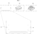
- FIG. 1 is a diagram illustrating a pouch type battery according to an embodiment of the present disclosure.
- the pouch type battery 100 includes a pouch 110, a first lead tab 120 which is electrically connected to a cathode (157 in FIG. 2 ) inside the pouch 110 and protrudes outside of the pouch 110, and a second lead tab 130 which is electrically connected to an anode (155 of FIG. 2 ) inside the pouch 110 and protrudes outside of the pouch 110.
- a negative voltage is applied or output by the first lead tab 120, and a positive voltage is applied or output by the second lead tab 130.
- the plurality of pouch type batteries 100 may form a battery module 200, and in the case where a plurality of battery modules 200 are provided, the plurality of battery modules 200 may form a battery pack 300.
- the pouch type battery 100 may be used in various applications, such as vehicles, energy storage devices, drones, and the like.
- the present disclosure provides a method for reducing problems, such as electrolyte leakage, swelling of the first lead tab 120 or the second lead tab 130, and the like, which may occur as the first lead tab 120 or the second lead tab 130 protrudes outside of the pouch 110.
- the present disclosure provides the first lead tab 120 or the second lead tab 130 which may improve an adhesive strength of a film to a metal, and may improve corrosion resistance to an electrolyte inside the pouch type battery.
- the first lead tab 120 which may improve an adhesive strength of a film to a metal, and may improve corrosion resistance to an electrolyte inside the pouch type battery, which will be described below in further detail with reference to FIG. 2 .
- FIG. 2 is a perspective diagram of the pouch type battery of FIG. 1 .
- the pouch type battery 100 includes the pouch 110, an anode 155 and a cathode 157 inside the pouch 110, a separation film 153 for separating the anode 155 and the cathode 157, an electrolyte inside the pouch 110, the first lead tab 120 which is electrically connected to the cathode 157 and protrudes outside of the pouch 110, and the second lead tab 130 which is electrically connected to the anode 155 and protrudes outside of the pouch 110.
- FIG. 2 illustrates an example where the separation film 153 is disposed below the cathode 157 and the anode 155 is disposed below the separation film 153, modifications may be made thereto.
- the separation film 153 may be disposed below the anode 155, and the cathode 157 may be disposed below the separation film 153.
- FIG. 2 illustrates an example where a battery cell 150 is provided inside the pouch 110, and the battery cell 150 includes the anode 155, the cathode 157, and the separation film 153 which separates the anode 155 and the cathode 157.
- the pouch 110 may be an aluminum pouch.
- the anode 155 may include aluminum, and the cathode 157 may include copper.
- the first lead tab 120 connected to the cathode 157 will be described below with reference to FIG. 3A and the following figures.
- the pouch type battery 100 may be manufactured in such a manner that: after the anode 155, the separation film 157, and the cathode 157 are arranged inside the pouch 110, the first lead tab 120 and the second lead tab 130 are disposed therein; after the electrolyte is injected into the pouch 110, gas is injected thereinto, and then the injected gas is removed therefrom; and encapsulation of the pouch 110 is performed.
- first lead tab 120 and the second lead tab 130 protrude outside of the pouch 110 with no electrolyte leaking to the outside.
- first lead tab 120 has corrosion resistance to the electrolyte.
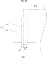
- FIGS. 3A and 3B are diagrams illustrating lead tabs of FIG. 2 .
- the lead tab 120 includes a metal 125, and a film 127 plated on at least one surface of the metal 125.
- the metal 125 may be plated with various copper-based metal layers, and the film 127 may be a polypropylene (PP) film. Particularly, the film 127 may be a sealing film.
- PP polypropylene
- the film 127 is attached to at least one surface of the metal 125 to prevent the electrolyte in the pouch 110 from leaking to the outside of the pouch 110.
- the film 127 is plated on both sides of the metal 125.
- the metal 125 is connected to the cathode 157 inside the pouch 110 and protrudes outside of the pouch 110.
- the film 127 when the film 127 is attached to the surface of the metal 125, it is desired that the film 127 is attached to the metal 125 based on a border BOR between the inside and the outside of the pouch 110. As the film 127 is attached to the metal 125, the electrolyte may be prevented from leaking to the outside of the pouch 110.
- a first area Ara of the film 127 inside the pouch 110 is greater than a second area Arb of the film 127 outside the pouch 110, as illustrated in FIG. 3A .
- a thickness of the film 127 or a thickness of the metal 125 may be the smallest at an area near the border BOR of the pouch 110, and may increase further away from the border BOR of the pouch 110.
- edges of the film 127 or the metal 125 are rounded to prevent damage.
- the second lead tab 130 includes a metal 135 and a film 137 plated on at least one surface of the metal 135 as illustrated in FIG. 3B .
- the film 137 when the film 137 is attached to the surface of the metal 135, it is desired that the film 137 is attached to the metal 135 based on the border BOR between the inside and the outside of the pouch 110. As the film 137 is attached to the metal 135, the electrolyte may be prevented from leaking to the outside of the pouch 110.
- the surface of the first lead tab 120 connected to the cathode 157 is at a higher risk of corrosion by the electrolyte.
- the present disclosure provides the first lead tab 120 having improved corrosion resistance to the electrolyte, which will be described below with reference to FIG. 4 and the following figures.
- FIG. 4 is a diagram illustrating a structure of a metal of FIG. 3A or 3B .
- the metal 125 in the first lead tab 120 includes a first metal layer 400, second metal layers 405a and 405b formed on the first metal layer 400, third metal layers 407a and 407b formed on the second metal layers 405a and 405b, and organic layers 409a and 409b formed on the third metal layers 407a and 407b.
- the second metal layers 405a and 405, the third metal layers 407a and 407b, and the organic layers 409a and 409b are plated on both sides based on the first metal layer 400.
- the first metal layer 400 includes copper (Cu)
- the second metal layers 405a and 405b include nickel (Ni)
- the third layers 407a and 407b include chromium (Cr).
- the second metal layers 405a and 405b are formed on the Copper (Cu)-based first metal layer 400 by performing nickel (Ni)-based electroplating; the third metal layers 407a and 47b are formed on the second metal layers 405a and 405b by performing chromium (Cr)-based electroless plating; and then, the organic layers 409a and 409b are formed thereon.
- a height h3 or a thickness of the third metal layers 407a and 407b may be in a range of 3 nm to 20 nm.
- the third metal layers 407a and 407b formed by the chromium (Cr)-based electroless plating may be thinner compared to electroplating, such that the thickness of the metal 125 may be reduced.
- Th organic layers 409a and 409b may include a silicon (Si)-based organic material, an inorganic material such as Zr, Co, Ti, Cr, Ni, and Mo, and the like.
- the organic layers 409a and 409b may prevent the electrolyte from permeating the metal 125, particularly between the metal 125 and the film 127, thereby preventing the electrolyte from leaking to the outside of the pouch 110.
- the organic layers 409a and 409b may prevent the electrolyte from permeating the chromium (Cr)-based third metal layers 407a and 407b of the metal 125, thereby producing the effect of preventing corrosion.
- the first metal layer 400 has the highest height h1
- the second metal layers 405a and 405b has the second highest height h2.
- the height h3 of the third metal layers 407a and 407b is lower than the height h2 of the second metal layers 405a and 405b, and the height h4 of the organic layers 409a and 409b is lower than the height h2 of the second metal layers 405a and 405b.
- a total thickness of the metal 125 may be reduced, and a possibility of electrolyte leakage may also be reduced by encapsulation of the pouch 110.
- the third metal layers 407a and 407b are plated on the second metal layers 405a and 405b by electroless plating, which will be described below with reference to FIGS. 5A to 7 .
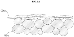
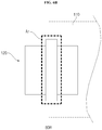
- FIGS. 5A and 5B are diagrams explaining an example where the third metal layers of FIG. 4 are plated by electroplating.
- FIG. 5A is a diagram illustrating a grain size of the second metal layers and a grain size of the third metal layers in the case where the third metal layers 407a and 407b of FIG. 4 are formed by chromium (Cr)-based electroplating.
- the grain size NGra of the second metal layers 405a and 405b is smaller than the grain size CGra of the third metal layers 407a and 407b.
- the grains of the third metal layers 407a and 407b, formed by electroplating, have a plate shape unlike the grains of the second metal layers 405a and 405b, such that the electrolyte may easily penetrate into the second metal layers 405a and 405b.
- the film 127 attached to the metal 125 may come off in an area Arx near the border BOR between the inside and the outside of the pouch 110.
- the electrolyte may leak at the border BOR between the inside and the outside of the pouch 110, or the metal 125 may be corroded.
- the present disclosure forms the third metal layers 407a and 407b by the chromium (Cr)-based electroless plating as illustrated in FIG. 4 .
- FIGS. 6A to 7 are diagrams explaining an example where the third metal layers of FIG. 4 are plated by electroless plating.
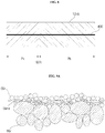
- FIG. 6A is a diagram illustrating a grain size of the second metal layers and a grain size of the third metal layers in the case where the third metal layers 407a and 407b of FIG. 4 are formed by chromium (Cr)-based electroless plating.
- the grain size NGr of the second metal layers 405a and 405b is smaller than the grain size CGr of the third metal layers 407a and 407b.
- the grains of the third metal layers 407a and 407b, formed by electroless plating, have a circular shape, similarly to the grains of the second metal layers 405a and 405b.
- the grains of the third metal layers 407a and 407b of FIG. 5A have a plate shape, but the grains of the third metal layers 407a and 407b of FIG. 6A have a circular shape.
- the grain size CGr of the third metal layers 407a and 407b plated by electroless plating is smaller than the grain size CGra of the third metal layers 407a and 407b plated by electroplating, such that density may be improved, and the electrolyte may be prevented from easily penetrating into the second metal layers 405a and 405b.
- the film 127 attached to the metal 125 is not separated from the metal 125 in the area (Ar) near the border BOR between the inside and the outside of the pouch 110, thereby preventing electrolyte leakage at the border BOR between the inside and the outside of the pouch 110, and preventing corrosion of the metal 125.
- FIG. 7 illustrates an example of digitizing an adhesive strength of a film to a metal including the third metal layers 407a and 407b plated by electroplating; and (b) illustrates an example of digitizing an adhesive strength of a film to a metal including the third metal layers 407a and 407b plated by electroless plating.
- Lb of (b) of FIG. 7 is higher than La of (a) of FIG. 7 by a value of Lc. That is, an adhesive strength of a film to a metal including the third metal layers 407a and 407b plated by electroless plating is improved, such that the film 127 attached to the metal 125 may not come off in the area Ar near the border BOR between the inside and the outside of the pouch 110, thereby preventing electrolyte leakage at the border BOR between the inside and the outside of the pouch 110, and preventing corrosion of the metal 125.
- FIG. 8 is a diagram illustrating a structure of a metal according to another embodiment of the present disclosure.
- a metal 125b includes a first metal layer 400, second metal layers 405a and 405 formed on the first metal layer 400, third metal layers 407a and 407b formed on the second metal layers 405a and 405b, and organic layers 409a and 409b formed on the third metal layers 407a and 407b.
- at least a portion of the third metal layers 407a and 407b may be plated on the second metal layers 405a and 405b by a combination of electroplating and electroless plating.
- a first area Pa of the metal 125b which corresponds to the inside of the pouch 110, is plated by a combination of electroplating and electroless plating, and a second area Pb of the metal 125b, which corresponds to the outside of the pouch 110, is plated by electroless plating.
- the third metal layers 407a and 407b are formed in the first area Pa of the metal 125b inside the pouch 110 by a hybrid method using a combination of electroplating and electroless plating, and the third metal layers 407a and 407b are formed in the second area Pb of the metal 125b outside the pouch 110 by electroless plating.
- FIGS. 9A to 10C are diagrams referred to in explaining FIG. 8 .
- FIG. 9A is a diagram illustrating a grain size of the second metal layers and a grain size of the third metal layers in the case where the third metal layers 407a and 407b in the first area (Pa) of FIG. 8 are formed by a combination of chromium (Cr)-based electroplating and electroless plating.
- Cr chromium
- the grain size NGr of the second metal layers 405a and 405b is smaller than the grain size CGr of the third metal layers 407a and 407b.
- the grains of the third metal layers 407a and 407b, formed by a combination of electroplating and electroless plating, may have both a plate shape and a circular shape.
- the grain size of the third metal layers 407a and 407b formed in the first area Pa of FIG. 9A may be more inhomogeneous than the grain size of the third metal layers 407a and 407b formed in the second area Pb of FIG. 9B . Accordingly, density of the third metal layers 407a and 407b in the first area Pa may be higher than density of the third metal layers 407a and 407b in the second area Pb, such that the electrolyte in the first area Pa may not easily penetrate into the second metal layers 405a and 405b.
- the film 127 attached to the metal 125b is not separated from the metal 125b in the area (Ar) near the border (BOR) between the inside and the outside of the pouch 110, thereby preventing electrolyte leakage at the border (BOR) between the inside and the outside of the pouch 110, and preventing corrosion of the metal 125b.
- FIG. 9B is a diagram illustrating a grain size of the second metal layers and a grain size of the third metal layers when the third metal layers 407a and 407b of FIG. 8 are formed by chromium (Cr)-based electroless plating.
- the grain size NGr of the second metal layers 405a and 405b is smaller than the grain size CGr of the third metal layers 407a and 407b.
- the grains of the third metal layers 407a and 407b, formed by electroless plating, may have a circular shape, similarly to the grains of the second metal layers 405a and 405b.
- the grains of the third metal layers 407a and 407b of FIG. 9C have a plate shape, while the grains of the third metal layers 407a and 407b of FIG. 9b have a circular shape.
- the grain size CGr of the third metal layers 407a and 407b plated by electroless plating is smaller than the grain size CGra of the third metal layers 407a and 407b plated by electroplating, such that density may be improved.
- FIG. 9B illustrates a grain size of the second metal layers and a grain size of the third metal layers when the third metal layers 407a and 407b formed in the second area Pb of FIG. 8 .
- FIG. 9C illustrates a grain size of the second metal layers and a grain size of the third metal layers when the third metal layers 407a and 407b of FIG. 8 are formed by chromium (Cr)-based electroplating.
- the grain size NGra of the second metal layers 405a and 405b is smaller than the grain size CGra of the third metal layers 407a and 407b.
- the grains of the third metal layers 407a and 407b, formed by electroplating have a plate shape, such that the electrolyte may easily penetrate into the second metal layers 405a and 405b.
- FIGS. 10A to 10C are diagrams illustrating current density versus voltage characteristics of the metal 125b with respect to the grains of the third metal layers 407a and 407b of FIGS. 9A to 9C .
- FIGS. 10A to 10C respectively illustrate Cu1, Cu2, and Cu3 which are curves of the current density versus voltage characteristics.
- stability of potential of the metal 125b is increased in the order of FIGS. 10A to 10C .
- the potential characteristics are related to separation of the film 127 from the metal 125b, in which as the potential is decreased, the film 127 is less likely to come off.
- the hybrid method using a combination of electroplating and electroless plating shows the lowest possibility of separation of the film 127 from the metal 125b; and the method of electroless plating illustrated in FIG. 9B or 10B shows a low possibility of separation of the film 127 from the metal 125b.
- FIG. 9C or 10C shows the highest possibility of separation of the film 127 from the metal 125b.
- the electrokinetic potential at the surface of the metal 125b may be gradually decreased in the order of FIGS. 10A to 10C .
- the electrokinetic potential at the surface of the metal 125b is in a range of -0.1 V to -0.6 V.
- FIG. 11 is a diagram illustrating a pouch type battery according to another embodiment of the present disclosure.
- the pouch type battery 1200 is similar to the pouch type battery 100 of FIG. 2 , but is different therefrom in that a first lead tab 1120, which is electrically connected to a cathode of the pouch 1110 and protrudes outside of the pouch 1110, and a second lead tab 1130, which is electrically connected to an anode of the pouch 1110 and protrudes outside of the pouch 1110, are formed at one of both ends of the pouch 1110.
- the first lead tab 120 and the second lead tab 130 are formed respectively at each of both ends of the pouch 1110; but as illustrated in FIG. 11 , the first lead tab 1120 and the second lead tab 1130 may also be formed on the same end of the pouch 1110.
- the first lead tab 1120 and the second lead tab 1130 may include the metals 1125 and 1135 and the films 1127 and 1137, respectively.
- FIGS. 1 to 10C may be applied to the metal 1125 and the film 1127 of the first lead tab 1120 which is electrically connected to the cathode.
- the lead tab and the pouch type battery including the same are not limited to the configuration and method of the aforementioned embodiments, and all or some of the above embodiments may be selectively combined with each other to enable various modifications thereof.
Landscapes
- Chemical & Material Sciences (AREA)
- Chemical Kinetics & Catalysis (AREA)
- Electrochemistry (AREA)
- General Chemical & Material Sciences (AREA)
- Engineering & Computer Science (AREA)
- Materials Engineering (AREA)
- Metallurgy (AREA)
- Organic Chemistry (AREA)
- Mechanical Engineering (AREA)
- Connection Of Batteries Or Terminals (AREA)
- Sealing Battery Cases Or Jackets (AREA)
- Secondary Cells (AREA)
Applications Claiming Priority (2)
| Application Number | Priority Date | Filing Date | Title |
|---|---|---|---|
| KR1020170140409A KR102517953B1 (ko) | 2017-10-26 | 2017-10-26 | 리드 탭 및 이를 구비하는 파우치형 배터리 |
| PCT/KR2018/012707 WO2019083298A1 (ko) | 2017-10-26 | 2018-10-25 | 리드 탭 및 이를 구비하는 파우치형 배터리 |
Publications (3)
| Publication Number | Publication Date |
|---|---|
| EP3703159A1 true EP3703159A1 (de) | 2020-09-02 |
| EP3703159A4 EP3703159A4 (de) | 2021-08-11 |
| EP3703159B1 EP3703159B1 (de) | 2026-04-22 |
Family
ID=66246901
Family Applications (1)
| Application Number | Title | Priority Date | Filing Date |
|---|---|---|---|
| EP18871576.7A Active EP3703159B1 (de) | 2017-10-26 | 2018-10-25 | Anschlusslasche und damit versehene pouch-batterie |
Country Status (5)
| Country | Link |
|---|---|
| EP (1) | EP3703159B1 (de) |
| JP (1) | JP7221953B2 (de) |
| KR (1) | KR102517953B1 (de) |
| CN (1) | CN109713206B (de) |
| WO (1) | WO2019083298A1 (de) |
Families Citing this family (2)
| Publication number | Priority date | Publication date | Assignee | Title |
|---|---|---|---|---|
| KR102582440B1 (ko) | 2021-02-08 | 2023-09-22 | 서명호 | 배터리 충전장치 |
| CN119833843A (zh) * | 2023-12-18 | 2025-04-15 | 重庆弗迪电池研究院有限公司 | 电池外壳、电池、电池组件及用电设备 |
Family Cites Families (20)
| Publication number | Priority date | Publication date | Assignee | Title |
|---|---|---|---|---|
| US6372381B1 (en) * | 1999-02-05 | 2002-04-16 | Rayovac Corporation | Duplex-coated cathode cans, and electrochemical cells made therewith |
| JP3833493B2 (ja) * | 2000-04-25 | 2006-10-11 | 日本電解株式会社 | Tab用テープキャリアに用いる銅箔並びにこの銅箔を用いたtab用キャリアテープ及びtab用テープキャリア |
| TW595280B (en) * | 2000-04-25 | 2004-06-21 | Nippon Denkai Kk | Copper foil for TAB tape carrier, TAB tape carrier using the copper foil and TAB carrier tape |
| WO2001097583A2 (en) * | 2000-06-12 | 2001-12-20 | Bourns, Inc. | Molded electronic assembly |
| JP3901495B2 (ja) * | 2001-11-13 | 2007-04-04 | 株式会社神戸製鋼所 | アルミニウム又はアルミニウム合金製リール |
| US7160647B2 (en) * | 2003-12-22 | 2007-01-09 | The Gillette Company | Battery cathode |
| JP5308696B2 (ja) * | 2008-03-17 | 2013-10-09 | 藤森工業株式会社 | 封止フィルムおよび封止フィルム付電極 |
| JP5684462B2 (ja) * | 2008-12-22 | 2015-03-11 | 昭和電工パッケージング株式会社 | 正極タブリード及び電池 |
| JP5546369B2 (ja) * | 2010-06-25 | 2014-07-09 | 千住金属工業株式会社 | 蓄電デバイス用電極、その製造方法及びその接続方法 |
| KR101029821B1 (ko) * | 2010-07-22 | 2011-04-18 | (주)케이비티 | 이차전지용 양극단자의 제조 방법 |
| JP5548827B2 (ja) * | 2010-08-09 | 2014-07-16 | エルジー・ケム・リミテッド | 安全性が向上した二次バッテリー |
| EP2602846B1 (de) * | 2011-06-30 | 2017-08-02 | LG Chem, Ltd. | Elektrodenanschluss für sekundärbatterien und lithiumsekundärbatterie damit |
| JP5959878B2 (ja) * | 2012-02-21 | 2016-08-02 | 藤森工業株式会社 | 電極リード線部材を備えた非水系電池用収納容器 |
| JP2013187077A (ja) * | 2012-03-08 | 2013-09-19 | Panasonic Corp | 捲回型およびスタック型電極電池 |
| KR101370265B1 (ko) * | 2012-04-17 | 2014-03-04 | 주식회사 엘지화학 | 이차전지, 이에 적용되는 이차전지용 부품 및 이차전지의 제조 방법 |
| JP6035900B2 (ja) * | 2012-06-28 | 2016-11-30 | Tdk株式会社 | 全固体リチウムイオン二次電池 |
| JP2014186914A (ja) * | 2013-03-25 | 2014-10-02 | Showa Denko Packaging Co Ltd | タブリード |
| US9812692B2 (en) * | 2013-07-30 | 2017-11-07 | Lg Chem, Ltd. | Lithium secondary battery having enhanced safety |
| JP6584088B2 (ja) * | 2015-02-23 | 2019-10-02 | 株式会社エンビジョンAescジャパン | タブリード及びそれを用いた二次電池 |
| JP6220359B2 (ja) * | 2015-03-26 | 2017-10-25 | Jx金属株式会社 | フィルム外装電池用タブリード材料及びその製造方法 |
-
2017
- 2017-10-26 KR KR1020170140409A patent/KR102517953B1/ko active Active
-
2018
- 2018-10-25 JP JP2020523425A patent/JP7221953B2/ja active Active
- 2018-10-25 WO PCT/KR2018/012707 patent/WO2019083298A1/ko not_active Ceased
- 2018-10-25 EP EP18871576.7A patent/EP3703159B1/de active Active
- 2018-10-26 CN CN201811257168.5A patent/CN109713206B/zh active Active
Also Published As
| Publication number | Publication date |
|---|---|
| JP7221953B2 (ja) | 2023-02-14 |
| CN109713206A (zh) | 2019-05-03 |
| CN109713206B (zh) | 2022-01-14 |
| JP2021500725A (ja) | 2021-01-07 |
| EP3703159B1 (de) | 2026-04-22 |
| WO2019083298A1 (ko) | 2019-05-02 |
| KR20190046515A (ko) | 2019-05-07 |
| KR102517953B1 (ko) | 2023-04-03 |
| EP3703159A4 (de) | 2021-08-11 |
Similar Documents
| Publication | Publication Date | Title |
|---|---|---|
| EP2750239B1 (de) | Gestufte elektrodenanordnung und batteriezelle damit | |
| JP5825436B2 (ja) | 電極タブ接合性に優れた電極組立体、これを含む電池セル、デバイス及びその製造方法 | |
| EP2750241B1 (de) | Elektrodenanordnung mit gestuften ebenen und batteriezelle, batteriepackung und vorrichtung damit | |
| JP6024070B2 (ja) | 電極組立体の製造方法及び電池セルの製造方法 | |
| JP6575557B2 (ja) | 全固体電池及び全固体電池の製造方法 | |
| KR101590259B1 (ko) | 전극 조립체, 이를 포함하는 전지 및 디바이스 | |
| JP2018133201A (ja) | 蓄電モジュール | |
| KR20130063709A (ko) | 이차전지용 파우치 외장재 및 이를 이용한 이차전지 | |
| WO2019073914A1 (ja) | 二次電池および二次電池の製造方法 | |
| EP3703159A1 (de) | Anschlusslasche und damit versehene pouch-batterie | |
| JP6938128B2 (ja) | 電池用集電体および電池 | |
| KR20210073669A (ko) | 음극 집전체, 그를 포함하는 음극 및 리튬이차전지 | |
| KR20170124302A (ko) | 플렉서블 이차 전지 | |
| CN103579573A (zh) | 产生用于电化学存储器的电极的联接接触的方法,制造电化学存储器的方法和电化学存储器 | |
| US11417868B2 (en) | Manufacturing method for secondary battery | |
| JP2018060699A (ja) | 積層型二次電池の製造方法 | |
| JP2017004892A (ja) | 蓄電素子、及び蓄電素子の製造方法 | |
| WO2019073916A1 (ja) | 二次電池および二次電池の製造方法 | |
| JP2018206490A (ja) | 二次電池およびその製造方法 | |
| KR20180080495A (ko) | 향상된 기계적 강도의 단면 전극을 포함하고 있는 전극조립체 | |
| KR20260007762A (ko) | 이차 전지 및 이차 전지 제조 방법 | |
| WO2024057710A1 (ja) | バイポーラ電極、バイポーラ電池、およびバイポーラ電極の製造方法 | |
| JP6115459B2 (ja) | 電極組立体の製造方法、蓄電装置及び電極組立体の製造装置 | |
| US20200259171A1 (en) | Lithium-ion rechargeable battery, multilayer structure for lithium-ion rechargeable battery, and method for manufacturing lithium-ion rechargeable battery | |
| CN121263890A (zh) | 蓄电装置 |
Legal Events
| Date | Code | Title | Description |
|---|---|---|---|
| STAA | Information on the status of an ep patent application or granted ep patent |
Free format text: STATUS: THE INTERNATIONAL PUBLICATION HAS BEEN MADE |
|
| PUAI | Public reference made under article 153(3) epc to a published international application that has entered the european phase |
Free format text: ORIGINAL CODE: 0009012 |
|
| STAA | Information on the status of an ep patent application or granted ep patent |
Free format text: STATUS: REQUEST FOR EXAMINATION WAS MADE |
|
| 17P | Request for examination filed |
Effective date: 20200525 |
|
| AK | Designated contracting states |
Kind code of ref document: A1 Designated state(s): AL AT BE BG CH CY CZ DE DK EE ES FI FR GB GR HR HU IE IS IT LI LT LU LV MC MK MT NL NO PL PT RO RS SE SI SK SM TR |
|
| AX | Request for extension of the european patent |
Extension state: BA ME |
|
| DAV | Request for validation of the european patent (deleted) | ||
| DAX | Request for extension of the european patent (deleted) | ||
| A4 | Supplementary search report drawn up and despatched |
Effective date: 20210714 |
|
| RIC1 | Information provided on ipc code assigned before grant |
Ipc: C23C 18/16 20060101AFI20210708BHEP Ipc: H01M 50/172 20210101ALI20210708BHEP Ipc: B32B 15/00 20060101ALI20210708BHEP Ipc: C25D 3/02 20060101ALI20210708BHEP Ipc: H01M 50/534 20210101ALI20210708BHEP Ipc: H01M 50/571 20210101ALI20210708BHEP Ipc: H01M 50/19 20210101ALI20210708BHEP Ipc: H01M 50/10 20210101ALI20210708BHEP Ipc: H01M 50/178 20210101ALI20210708BHEP Ipc: H01M 50/188 20210101ALI20210708BHEP |
|
| RAP1 | Party data changed (applicant data changed or rights of an application transferred) |
Owner name: LG CHEM, LTD. |
|
| REG | Reference to a national code |
Ref country code: DE Ref legal event code: R079 Free format text: PREVIOUS MAIN CLASS: H01M0002260000 Ipc: C23C0018160000 Ref document number: 602018090852 Country of ref document: DE |
|
| GRAP | Despatch of communication of intention to grant a patent |
Free format text: ORIGINAL CODE: EPIDOSNIGR1 |
|
| STAA | Information on the status of an ep patent application or granted ep patent |
Free format text: STATUS: GRANT OF PATENT IS INTENDED |
|
| RIC1 | Information provided on ipc code assigned before grant |
Ipc: C23C 18/16 20060101AFI20251104BHEP Ipc: H01M 50/172 20210101ALI20251104BHEP Ipc: B32B 15/00 20060101ALI20251104BHEP Ipc: C25D 3/02 20060101ALI20251104BHEP Ipc: H01M 50/534 20210101ALI20251104BHEP Ipc: H01M 50/571 20210101ALI20251104BHEP Ipc: H01M 50/19 20210101ALI20251104BHEP Ipc: H01M 50/10 20210101ALI20251104BHEP Ipc: H01M 50/178 20210101ALI20251104BHEP Ipc: H01M 50/188 20210101ALI20251104BHEP Ipc: C23C 18/31 20060101ALI20251104BHEP Ipc: C25D 3/12 20060101ALI20251104BHEP Ipc: C25D 3/04 20060101ALI20251104BHEP Ipc: C25D 5/00 20060101ALI20251104BHEP Ipc: C25D 7/00 20060101ALI20251104BHEP Ipc: H01M 50/105 20210101ALI20251104BHEP |
|
| INTG | Intention to grant announced |
Effective date: 20251201 |
|
| GRAS | Grant fee paid |
Free format text: ORIGINAL CODE: EPIDOSNIGR3 |
|
| GRAA | (expected) grant |
Free format text: ORIGINAL CODE: 0009210 |
|
| STAA | Information on the status of an ep patent application or granted ep patent |
Free format text: STATUS: THE PATENT HAS BEEN GRANTED |
|
| AK | Designated contracting states |
Kind code of ref document: B1 Designated state(s): AL AT BE BG CH CY CZ DE DK EE ES FI FR GB GR HR HU IE IS IT LI LT LU LV MC MK MT NL NO PL PT RO RS SE SI SK SM TR |
|
| REG | Reference to a national code |
Ref country code: CH Ref legal event code: F10 Free format text: ST27 STATUS EVENT CODE: U-0-0-F10-F00 (AS PROVIDED BY THE NATIONAL OFFICE) Effective date: 20260422 Ref country code: GB Ref legal event code: FG4D |