EP3693221B1 - Interior decorating material for vehicle - Google Patents
Interior decorating material for vehicle Download PDFInfo
- Publication number
- EP3693221B1 EP3693221B1 EP18864096.5A EP18864096A EP3693221B1 EP 3693221 B1 EP3693221 B1 EP 3693221B1 EP 18864096 A EP18864096 A EP 18864096A EP 3693221 B1 EP3693221 B1 EP 3693221B1
- Authority
- EP
- European Patent Office
- Prior art keywords
- wall
- lens
- light guide
- interior member
- guide member
- Prior art date
- Legal status (The legal status is an assumption and is not a legal conclusion. Google has not performed a legal analysis and makes no representation as to the accuracy of the status listed.)
- Active
Links
Images


Classifications
-
- B—PERFORMING OPERATIONS; TRANSPORTING
- B60—VEHICLES IN GENERAL
- B60Q—ARRANGEMENT OF SIGNALLING OR LIGHTING DEVICES, THE MOUNTING OR SUPPORTING THEREOF OR CIRCUITS THEREFOR, FOR VEHICLES IN GENERAL
- B60Q3/00—Arrangement of lighting devices for vehicle interiors; Lighting devices specially adapted for vehicle interiors
- B60Q3/50—Mounting arrangements
- B60Q3/51—Mounting arrangements for mounting lighting devices onto vehicle interior, e.g. onto ceiling or floor
-
- B—PERFORMING OPERATIONS; TRANSPORTING
- B60—VEHICLES IN GENERAL
- B60J—WINDOWS, WINDSCREENS, NON-FIXED ROOFS, DOORS, OR SIMILAR DEVICES FOR VEHICLES; REMOVABLE EXTERNAL PROTECTIVE COVERINGS SPECIALLY ADAPTED FOR VEHICLES
- B60J5/00—Doors
-
- B—PERFORMING OPERATIONS; TRANSPORTING
- B60—VEHICLES IN GENERAL
- B60Q—ARRANGEMENT OF SIGNALLING OR LIGHTING DEVICES, THE MOUNTING OR SUPPORTING THEREOF OR CIRCUITS THEREFOR, FOR VEHICLES IN GENERAL
- B60Q3/00—Arrangement of lighting devices for vehicle interiors; Lighting devices specially adapted for vehicle interiors
- B60Q3/20—Arrangement of lighting devices for vehicle interiors; Lighting devices specially adapted for vehicle interiors for lighting specific fittings of passenger or driving compartments; mounted on specific fittings of passenger or driving compartments
- B60Q3/217—Doors, e.g. door sills; Steps
-
- B—PERFORMING OPERATIONS; TRANSPORTING
- B60—VEHICLES IN GENERAL
- B60Q—ARRANGEMENT OF SIGNALLING OR LIGHTING DEVICES, THE MOUNTING OR SUPPORTING THEREOF OR CIRCUITS THEREFOR, FOR VEHICLES IN GENERAL
- B60Q3/00—Arrangement of lighting devices for vehicle interiors; Lighting devices specially adapted for vehicle interiors
- B60Q3/20—Arrangement of lighting devices for vehicle interiors; Lighting devices specially adapted for vehicle interiors for lighting specific fittings of passenger or driving compartments; mounted on specific fittings of passenger or driving compartments
- B60Q3/225—Small compartments, e.g. glove compartments
-
- B—PERFORMING OPERATIONS; TRANSPORTING
- B60—VEHICLES IN GENERAL
- B60Q—ARRANGEMENT OF SIGNALLING OR LIGHTING DEVICES, THE MOUNTING OR SUPPORTING THEREOF OR CIRCUITS THEREFOR, FOR VEHICLES IN GENERAL
- B60Q3/00—Arrangement of lighting devices for vehicle interiors; Lighting devices specially adapted for vehicle interiors
- B60Q3/50—Mounting arrangements
- B60Q3/54—Lighting devices embedded in interior trim, e.g. in roof liners
-
- B—PERFORMING OPERATIONS; TRANSPORTING
- B60—VEHICLES IN GENERAL
- B60Q—ARRANGEMENT OF SIGNALLING OR LIGHTING DEVICES, THE MOUNTING OR SUPPORTING THEREOF OR CIRCUITS THEREFOR, FOR VEHICLES IN GENERAL
- B60Q3/00—Arrangement of lighting devices for vehicle interiors; Lighting devices specially adapted for vehicle interiors
- B60Q3/60—Arrangement of lighting devices for vehicle interiors; Lighting devices specially adapted for vehicle interiors characterised by optical aspects
- B60Q3/62—Arrangement of lighting devices for vehicle interiors; Lighting devices specially adapted for vehicle interiors characterised by optical aspects using light guides
- B60Q3/64—Arrangement of lighting devices for vehicle interiors; Lighting devices specially adapted for vehicle interiors characterised by optical aspects using light guides for a single lighting device
-
- B—PERFORMING OPERATIONS; TRANSPORTING
- B60—VEHICLES IN GENERAL
- B60Q—ARRANGEMENT OF SIGNALLING OR LIGHTING DEVICES, THE MOUNTING OR SUPPORTING THEREOF OR CIRCUITS THEREFOR, FOR VEHICLES IN GENERAL
- B60Q3/00—Arrangement of lighting devices for vehicle interiors; Lighting devices specially adapted for vehicle interiors
- B60Q3/70—Arrangement of lighting devices for vehicle interiors; Lighting devices specially adapted for vehicle interiors characterised by the purpose
- B60Q3/78—Arrangement of lighting devices for vehicle interiors; Lighting devices specially adapted for vehicle interiors characterised by the purpose for generating luminous strips, e.g. for marking trim component edges
-
- B—PERFORMING OPERATIONS; TRANSPORTING
- B60—VEHICLES IN GENERAL
- B60R—VEHICLES, VEHICLE FITTINGS, OR VEHICLE PARTS, NOT OTHERWISE PROVIDED FOR
- B60R13/00—Elements for body-finishing, identifying, or decorating; Arrangements or adaptations for advertising purposes
- B60R13/02—Internal Trim mouldings ; Internal Ledges; Wall liners for passenger compartments; Roof liners
-
- F—MECHANICAL ENGINEERING; LIGHTING; HEATING; WEAPONS; BLASTING
- F21—LIGHTING
- F21V—FUNCTIONAL FEATURES OR DETAILS OF LIGHTING DEVICES OR SYSTEMS THEREOF; STRUCTURAL COMBINATIONS OF LIGHTING DEVICES WITH OTHER ARTICLES, NOT OTHERWISE PROVIDED FOR
- F21V17/00—Fastening of component parts of lighting devices, e.g. shades, globes, refractors, reflectors, filters, screens, grids or protective cages
- F21V17/08—Fastening of component parts of lighting devices, e.g. shades, globes, refractors, reflectors, filters, screens, grids or protective cages onto the supporting or suspending arrangements of the lighting device, e.g. power cords, standards
-
- F—MECHANICAL ENGINEERING; LIGHTING; HEATING; WEAPONS; BLASTING
- F21—LIGHTING
- F21V—FUNCTIONAL FEATURES OR DETAILS OF LIGHTING DEVICES OR SYSTEMS THEREOF; STRUCTURAL COMBINATIONS OF LIGHTING DEVICES WITH OTHER ARTICLES, NOT OTHERWISE PROVIDED FOR
- F21V5/00—Refractors for light sources
-
- F—MECHANICAL ENGINEERING; LIGHTING; HEATING; WEAPONS; BLASTING
- F21—LIGHTING
- F21V—FUNCTIONAL FEATURES OR DETAILS OF LIGHTING DEVICES OR SYSTEMS THEREOF; STRUCTURAL COMBINATIONS OF LIGHTING DEVICES WITH OTHER ARTICLES, NOT OTHERWISE PROVIDED FOR
- F21V5/00—Refractors for light sources
- F21V5/04—Refractors for light sources of lens shape
-
- G—PHYSICS
- G02—OPTICS
- G02B—OPTICAL ELEMENTS, SYSTEMS OR APPARATUS
- G02B6/00—Light guides; Structural details of arrangements comprising light guides and other optical elements, e.g. couplings
- G02B6/0001—Light guides; Structural details of arrangements comprising light guides and other optical elements, e.g. couplings specially adapted for lighting devices or systems
- G02B6/0005—Light guides; Structural details of arrangements comprising light guides and other optical elements, e.g. couplings specially adapted for lighting devices or systems the light guides being of the fibre type
- G02B6/001—Light guides; Structural details of arrangements comprising light guides and other optical elements, e.g. couplings specially adapted for lighting devices or systems the light guides being of the fibre type the light being emitted along at least a portion of the lateral surface of the fibre
-
- B—PERFORMING OPERATIONS; TRANSPORTING
- B60—VEHICLES IN GENERAL
- B60R—VEHICLES, VEHICLE FITTINGS, OR VEHICLE PARTS, NOT OTHERWISE PROVIDED FOR
- B60R13/00—Elements for body-finishing, identifying, or decorating; Arrangements or adaptations for advertising purposes
- B60R13/02—Internal Trim mouldings ; Internal Ledges; Wall liners for passenger compartments; Roof liners
- B60R13/0237—Side or rear panels
- B60R13/0243—Doors
-
- B—PERFORMING OPERATIONS; TRANSPORTING
- B60—VEHICLES IN GENERAL
- B60R—VEHICLES, VEHICLE FITTINGS, OR VEHICLE PARTS, NOT OTHERWISE PROVIDED FOR
- B60R7/00—Stowing or holding appliances inside vehicle primarily intended for personal property smaller than suit-cases, e.g. travelling articles, or maps
- B60R7/04—Stowing or holding appliances inside vehicle primarily intended for personal property smaller than suit-cases, e.g. travelling articles, or maps in driver or passenger space, e.g. using racks
- B60R7/046—Stowing or holding appliances inside vehicle primarily intended for personal property smaller than suit-cases, e.g. travelling articles, or maps in driver or passenger space, e.g. using racks mounted on door
-
- F—MECHANICAL ENGINEERING; LIGHTING; HEATING; WEAPONS; BLASTING
- F21—LIGHTING
- F21W—INDEXING SCHEME ASSOCIATED WITH SUBCLASSES F21K, F21L, F21S and F21V, RELATING TO USES OR APPLICATIONS OF LIGHTING DEVICES OR SYSTEMS
- F21W2106/00—Interior vehicle lighting devices
Definitions
- the present invention relates to a vehicle interior member configured to be fitted on a vehicle.
- a known door lining fitted on a vehicle door is provided with a linear light guide member for transmitting light from a light source, and a lens provided along the light guide member, and these components are positioned between a door lining main body and a switch panel.
- the lens is provided with a groove that retains the light guide member, a clamped portion that is clamped between the door lining main body and the switch panel, and engagement claws that are engaged by through holes provided in the door lining main body.
- the light guide member is connected to the door lining main body via the lens. A part of the light emitted from the light source is irradiated from a side surface of the light guide member, and reaches the cabin after passing through the clamped portion of the lens.
- Patent Document 1 JP2015-155298A
- DE 10 2014 019607 A discloses a decorative part for a motor vehicle comprising first and second parts, the second part being illuminated from the rear by a light guide.
- JP 2013 100100 A discloses a vehicle interior material comprising a lens that houses a light guide, the lens being supported between junctions of the interior material.
- Patent Document 1 since the lens is clamped between the door lining main body and the switch panel, at the time of assembly, it is necessary to properly position the lens with respect to the door lining main body and the switch panel when clamping the lens between the door lining main body and the switch panel. Therefore, the assembly work is not simple.
- a primary object of the present invention is to provide a structure for a vehicle interior member having an interior member main body, a light guide member for conducting light from a light source, and a lens extending along the light guide member that allows the light guide member to be easily connected to the interior member main body.
- the present invention provides an interior member for a vehicle, comprising: an interior member main body forming an inner wall of a cabin; a linear light guide member configured to conduct light from a light source in a lengthwise direction and to irradiate the light from a side surface thereof; and a lens that transmits the light irradiated from the light guide member, the lens including a first wall extending along the light guide member, and a second wall and a third wall extending from either side edge of the first wall toward the light guide member; characterized in that: the lens extends along the light guide member, and is provided with a groove receiving the light guide member therein, the groove being defined by the first wall, the second wall and the third wall, the lens being further provided with a first engaging portion provided on a wall that defines the groove, and a second engaging portion provided on a wall that defines the groove, and the interior member main body being provided with a first engaged portion engaged by the first engaging portion, and a second engaged portion engaged by the second engaging portion, the lens being resiliently deformable
- the first engaging portion and the second engaging portion can be brought into engagement with the first engaged portion and the second engaged portion, respectively, with ease.
- the interior member main body and the lens can be joined to each other so that the lens and the light guide member can be mounted to the interior member main body with ease.
- the lens being resiliently deformed so as to cause the second wall and the third wall to come toward each other with ease, and a groove is thereby formed in the lens.
- the lens Since the lens is received in the interior member recess, the occupant is prevented from touching the lens so that damages to the lens can be avoided. Since the first engaging portion and the second engaging portion project in mutually opposing directions, and the lens and the interior member are joined to each other at the first engaging portion and the second engaging portion, the lens and the interior member can be firmly joined to each other.
- a projecting amount (L1) of the first engaging portion from the surface of the second wall is smaller than a projecting amount (L2) of the second engaging portion from the surface of the third wall.
- the deformation of the lens that is required in the assembling process can be minimized by engaging the second engaging portion with the second engaged portion, and then engaging the first engaging portion with the first engaged portion so that the process of joining the lens to the interior member main body is facilitated.
- the second engaged portion is passed through the wall part defining the interior member recess, and the second engaging portion is passed through the second engaged portion.
- the connection between the lens and the interior member main body can be made highly firm.
- the second engaging portion is formed in a free end edge of the third wall.
- the opening region of the groove can be reinforced by the second engaging portion.
- the first engaging portion includes a plurality of first engaging portions arranged in the extending direction of the lens
- the second engaging portion includes a plurality of second engaging portions arranged in the extending direction of the lens, the second engaging portions being each interposed between a corresponding mutually adjoining pair of the first engaging portions.
- the lens can be attached to the interior member main body with ease. Since the first engaging portions and the second engaging portions are provided in mutually different positions along the extending direction of the lens, the attachment strength between the lens and the interior member main body can be maximized.
- the interior member main body includes a plate like main board (10) provided on a door panel (3) of a vehicle door (2), and a pocket member (11, 12) disposed on an inner side of the main board and defining a door pocket (6) in cooperation with the main body, and the light guide member and the lens are provided on at least one of the main board and the pocket member.
- the interior of the door pocket can be illuminated.
- the door pocket extends in a fore and aft direction on the vehicle door
- the interior member recess is formed in a wall surface of at least one of the main board and the pocket member on an inside of the door pocket, the interior member recess extending linearly along an extending direction of the door pocket.
- the door pocket can be illuminated along the extending direction of the door pocket. Since the light guide member is formed as a linear member, the light guide member can be connected to the interior member main body without bending so that the assembly work is facilitated, and the light guide member is protected from being damaged.
- the interior member recess is defined by an upper wall (30), a side wall (31) and a lower wall (32), the lower wall inclining downward toward an inner part of the door pocket.
- the light from the lens can illuminate a lower part of the door pocket so that the visibility of the storage space in the door pocket can be improved.
- the upper wall defining the interior member recess is disposed substantially horizontally.
- the light irradiated upward from the lens is shielded by the upper wall so that the visibility of the storage space in the door pocket can be improved.
- the present invention thus provides a structure for a vehicle interior member having an interior member main body, a light guide member for conducting light from a light source, and a lens extending along the light guide member that allows the light guide member to be easily connected to the interior member main body.
- the lens includes a first wall extending along the light guide member, and a second wall and a third wall extending from either side edge of the first wall toward the light guide member, the groove being defined by the first wall, the second wall and the third wall, the lens being resiliently deformed so as to cause the second wall and the third wall to come toward each other with ease, and a groove is thereby formed in the lens.
- the lens Since the lens is received in the interior member recess, and the first engaging portion and the second engaging portion project in mutually opposing directions, the occupant is prevented from touching the lens so that damages to the lens can be avoided, and the lens and the interior member can be firmly joined to each other.
- the lens can be joined to the interior member main body with ease by engaging the second engaging portion with the second engaged portion, and then engaging the first engaging portion with the first engaged portion. At this time, the deformation of the lens that is required in the assembling process can be minimized, and the process of assembling the lens to the interior member main body can be facilitated
- the strength of the connection between the lens and the interior member main body can be further improved.
- the opening region of the groove can be reinforced by the second engaging portion.
- the lens can be easily and firmly attached to the interior member main body along the extending direction of the lens.
- the interior member main body includes a plate like main board provided on a door panel of a vehicle door, and a pocket member disposed on an inner side of the main board and defining a door pocket in cooperation with the main body, and the light guide member and the lens are provided on at least one of the main board and the pocket member, the interior of the door pocket can be illuminated.
- the door pocket extends in a fore and aft direction on the vehicle door, and the interior member recess is formed in a wall surface of at least one of the main board and the pocket member on an inside of the door pocket, the interior member recess extending linearly along an extending direction of the door pocket, the door pocket can be illuminated along the extending direction of the door pocket.
- the light guide member can be connected to the interior member main body without bending, the assembling process is facilitated, and the light guide member is protected from damages.
- the interior member recess is defined by an upper wall, a side wall and a lower wall, the lower wall inclining downward toward an inner part of the door pocket, the light from the lens can illuminate a lower part of the door pocket so that the visibility of the storage space in the door pocket can be improved.
- the upper wall defining the interior member recess is disposed substantially horizontally, the light irradiated upward from the lens is shielded by the upper wall so that the visibility of the storage space in the door pocket can be improved.
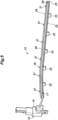
- a vehicle interior member according to an embodiment of the present invention as applied to a door trim of a vehicle door on a right front seat of a vehicle is described in the following with reference to the drawings.
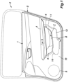
- a door trim 1 (interior member of a vehicle) covers an inboard surface of a door panel 3 which is a structural member of the door 2, and forms an inner wall of a cabin.
- the door panel 3 has an inner panel and an outer panel formed from sheet steel.
- the outer panel defines the outer surface of the vehicle body, and the inner panel is disposed on the inboard side of the outer panel, and is connected to the outer panel.
- the door trim 1 is formed in a plate shape by a plurality of members each made of plastic material, and is arranged so that a major plane of the door trim 1 faces laterally on the inboard side of the door panel 3 or, more specifically, on the inboard side of the inner panel.
- a substantially vertically middle part of the door trim 1 is formed with an armrest 4 that bugles in the inboard direction.
- the armrest 4 extends in the fore and aft direction from a middle part of the door trim 1 to the rear edge thereof.
- the upper surface of the armrest 4 is provided with a switch for controlling a window regulator and a lighting fixture of the cabin.
- a speaker grill 5 is provided in a lower front part of the door trim 1.
- a door pocket 6 extends in the fore and aft direction behind the speaker grill 5 and under the armrest 4.
- the door pocket 6 is provided with a pocket recess 8 that has an open upper end, and defines a storage space 7 therein.
- the door trim 1 includes a plate shaped main board 10 serving as a base member.
- the peripheral portion of the main board 10 extends toward the inner panel, and is connected to the inner panel.
- a gap is formed between the inner panel and the main board 10.
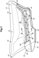
- the main board 10 has a through hole 9 passed laterally therethrough at a position corresponding to the door pocket 6.
- the door trim 1 is provided with an outer board 11 connected to an outboard surface of the main board 10 so as to cover the through hole 9 from the outboard side, and an inner board 12 interposed between the main board 10 and the outer board 11 and connected to the outboard side of the main board 10.
- the main board 10, the outer board 11, and the inner board 12 jointly form the main body (interior member main body) of the door trim 1.
- the inner board 12 is formed in a plate shape, and extends in the fore and aft direction along the lower edge of the through hole 9 of the main board 10 on the outboard side of the main board 10.
- the inner board 12 is thus positioned along the lower edge of the through hole 9.
- the outer board 11 is formed in a plate shape, and generally corresponds to the through hole 9 of the main board 10 and the inner board 12 in shape.
- the outer board 11 protrudes in the inboard direction at the peripheral part thereof, and is recessed in the outboard direction at the center.
- Screw holes 13 are formed in the peripheral part of the outer board 11, and the front edge part, the lower edge part, and the rear edge of the inner board 12 so that the inner board 12 and the outer board 11 are jointly fastened to the main board 10.
- the door pocket 6 is thus formed by fastening the inner board 12 and the outer board 11 to the main board 10. Therefore, the inner board 12 and the outer board 11 function as a pocket member forming a door pocket in cooperation with the main board 10.
- the inner board 12 forms the inboard wall of the storage space 7, and the outer board 11 forms the outboard wall of the storage space 7.
- the front edge of the inner board 12 extends forward from the gap between the main board 10 and the outer board 11 beyond the front edge of the outer board 11.
- the front edge of the inner board 12 is located between the inner panel and the main board 10.
- the inner board 12 is provided with a lighting device 15.
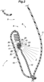
- the lighting device 15 includes a light emitting member 16 including a light source, a light guide member 17, and a lens 18 connecting the light guide member 17 to the inner board 12.
- the light emitting member 16 includes a circuit board (not shown) provided with an LED device, a lens (not shown) for concentrating the light emitted from the LED device at a predetermined position, and a holder 19 for accommodating the circuit board and the lens therein. As shown in Figures 1 and 4 , the light emitting member 16 is fastened to the outboard surface of a front part of the inner board 12. The light emitting member 16 is electrically connected to a prescribed power supply (not shown) mounted on the vehicle body. The LED device functions as a light source, and is controlled by the switch provided on the armrest 4. A prescribed bolt hole is provided in the holder 19, and the light emitting member 16 is fastened to the inner board 12.
- the light guide member 17 is formed of a highly transparent resin.
- the light guide member 17 is formed in a linear shape (wire shape), and has a circular cross section taken along a plane perpendicular to the longitudinal direction, or in cross section. As shown in Figure 4 , the light guide member 17 extends rearward from the light emitting member 16 along the inner board 12, and reaches the rear end of the inner board 12. One end of the light guide member 17 is coupled to the light emitting member 16. Light emitted from the LED device is collected by the lens of the light emitting member 16 and is incident to an end of the light guide member 17 coupled to the light emitting member 16.
- the light guide member 17 transmits the incident light along the lengthwise direction, and emits the incident light from the outer peripheral side surface thereof.
- the light guide member 17 may consist of an optical fiber cable configured to emit light from the side surface thereof by having a core member mixed with a material that diffuses the transmitted light, or a core member with an irregular circumferential surface that diffuses the transmitted light.
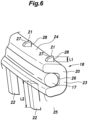
- the lens 18 is formed of a highly transparent resin that transmits light emitted from the light guide member 17. As shown in Figures 5 and 6 , the lens 18 includes a lens main body 20 extending along the lengthwise direction of the light guide member 17, a plurality of engagement claws 21 (first engagement portions) protruding from the outer surface of the lens main body 20, and a plurality of engagement projections 22 (second engagement portions) protruding from the outer surface of the lens main body 20.
- the lens main body 20 includes a first wall 23 provided along the light guide member 17, and a second wall 24 and a third wall 25 protruding from either side end of the first wall 23 toward the light guide member 17.
- the first wall 23, the second wall 24, and the third wall 25 jointly form a groove 26 in the lens main body 20 so as to be recessed in a direction perpendicular to the extending direction thereof.
- the lens main body 20 thus has a substantially U-shaped cross section with an open side facing in the inboard direction.
- the light guide member 17 is received in the groove 26.
- the light guide member 17 is located between the second wall 24 and the third wall 25.
- the first wall 23, the second wall 24, and the third wall 25 each extend along the extending direction of the light guide member 17, and the groove 26 is formed so as to extend along the extending direction of the lens main body 20.
- the diameter of the light guide member 17 is slightly larger than the distance between the second wall 24 and the third wall 25, and the light guide member 17 is press-fitted into the groove 26.
- the light guide member 17 is thus held between the second wall 24 and the third wall 25, and connected to the lens main body 20.
- the light emitted from the side surface of the light guide member 17 passes through the lens main body 20 and is emitted from the outer surface of the lens 18.
- the engagement claws 21 protrude from the surface of the second wall 24 facing away from the light guide member 17 (hereinafter, referred to as the outer surface of the second wall 24), or, in other words, from the upper surface of the second wall 24, and are arranged along the extending direction of the lens main body 20 substantially at regular intervals.
- Each engagement claw 21 is provided with an inclined surface 27 which is inclined so as to come close to the light guide member 17 toward the opening direction of the groove 26, and an engagement surface 28 which is formed at an end of the inclined surface 27 remote from the opening of the groove 26 and substantially perpendicular to the outer surface of the second wall 24, and is thus claw-shaped.
- the lens 18 is provided with six engagement claws 21.
- the engagement projections 22 project from a surface of the third wall 25 facing away from the light guide member 17 (hereinafter, referred to as an outer surface of the third wall 25), or, in other words, the lower surface of the third wall 25 and are arranged at substantially equal intervals in the extending direction of the lens main body 20.
- the engagement projections 22 protrude in a direction opposite to the direction in which the engagement claws 21 protrude in a cross-sectional view of the lens main body 20.
- Each engagement projection 22 is plate shaped, and has a major plane parallel to the extending direction of the lens main body 20.
- the engagement projections 22 are each formed at a substantially central position between two mutually adjoining engagement claws 21 with respect to the extending direction of the lens main body 20.
- the engagement claws 21 and the engagement projections 22 alternately protrude upward and downward, respectively, along the extending direction of the lens main body 20, and are thus arranged in a staggered manner.
- the lens 18 is provided with five engagement projections 22.
- the amount of protrusion of each engagement claw 21 from the outer surface of the second wall 24 (L1 in Figure 6 ) is selected to be smaller than the amount of protrusion of each engagement projection 22 from the outer surface of the third wall 25 (L2 in Figure 6 ).
- each engagement projection 22 is provided on the free end of the outer surface of the third wall 25, or, in other words, at the end of the third wall 25 on side of the groove 26. Thereby, the opening edge of the groove 26 is reinforced, and damage to the lens 18 can be prevented.
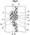
- FIG. 9 shows the lens 18 before deformation in a broken line, and the lens 18 after deformation in a solid line.
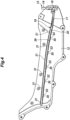
- the inner board 12 is formed with a board recess 29 (interior member recess) that is recessed in the outboard direction.
- the board recess 29 extends substantially linearly rearward from the position where the light emitting member 16 is attached to the inner board 12.
- the board recess 29 receives the lens 18 and the light guide member 17 therein.
- the light guide member 17 extends from the light emitting member 16 along the board recess 29, between the outer board 11 and the inner board 12, and reaches the interior of the pocket recess 8.
- the lens 18 extends in the fore and aft direction along the light guide member 17 inside the pocket recess 8.
- the light emitted from the LED device reaches the pocket recess 8 via the light guide member 17.
- the light emitted from the side surface of the light guide member 17 reaches the storage space 7 through the lens 18, and illuminates the storage space 7. Therefore, the occupant can easily visually recognize the stored items inside the storage space 7.
- the lens 18 is provided so as to extend only along the part of the light guide member 17 located inside the pocket recess 8, but, alternatively, the lens 18 may extend additionally along the part of the light guide member 17 extending from the light emitting member 16 to the pocket recess 8.
- a door pocket 6 is formed in the door trim 1 so as to extend in the fore and aft direction.
- the board recess 29 also extends substantially in the fore and aft direction so as to correspond with the door pocket 6.
- the light guide member 17 also extends along the direction in which the door pocket 6 extends. Therefore, the storage space 7 is illuminated over the entire fore and aft length thereof.
- the board recess 29 extends substantially linearly, the light guide member 17 can be received in the board recess 29 without being bent so that the damage to the light guide member 17 that could be caused by bending can be avoided.
- the upper surface of the board recess 29 is defined by an upper wall 30, the inboard surface by an inboard wall 31, and the lower surface by a lower wall 32.
- the upper wall 30 and the lower wall 32 face each other.
- the lens 18 is arranged such that the outer surface of the second wall 24 thereof faces upward, the outer surface of the third wall 25 thereof faces downward, and the first wall 23 thereof closes the opening of the board recess 29 while spaced from the inboard wall 31.
- the first wall 23, the second wall 24, the third wall 25, and the inboard wall 31 jointly define a receiving chamber 33 that receives the light guide member 17.
- the light guide member 17 is surrounded by the first wall 23, the second wall 24, the third wall 25, and the inboard wall 31 in the receiving chamber 33 so that the movement of the light guide member 17 in the vertical and lateral directions is restricted.
- the upward movement of the lens main body 20 is restricted by the upper wall 30, and the downward movement of the lens main body 20 is restricted by the lower wall 32.
- the mutually opposing wall surfaces of the upper wall 30 and the lower wall 32 respectively contact the second wall 24 and the third wall 25, respectively, when the lens main body 20 is received in the board recess 29. Since the second wall 24 abuts on the upper wall 30 and the third wall 25 abuts on the lower wall 32, the lens 18 is prevented from being dislodged from the board recess 29.
- a first receiving hole 34 (first engaged portion) is passed vertically through the part of the upper wall 30 corresponding to each engagement claw 21.
- a second receiving hole 35 (second engaged portion) is passed vertically through the part of the lower wall 32 corresponding to each engagement projection 22.
- six first receiving holes 34 and five second receiving holes 35 are formed in the inner board 12.
- each engagement claw 21 is fitted in the corresponding first receiving hole 34. Once the engagement claw 21 is received in the first receiving hole 34, the engagement surface 28 of the engagement claw 21 contacts a wall surface defining the first receiving hole 34 so that the movement of the upper part of the lens 18 in the lateral direction is restricted.
- each engagement projection 22 is fitted in the corresponding second receiving hole 35. Owing to the engagement between the engagement projection 22 and the second receiving hole 35, the lower part of the lens 18 is restricted from moving in the lateral direction. Since the engagement projection 22 is passed through the second receiving hole 35, the movement of the lower part of the lens 18 in the lateral direction is restricted in a highly reliable manner.
- each first receiving hole 34 extends through the upper wall 30 and an upper part of the inboard wall 31.
- each second receiving hole 35 extends through the lower wall 32 and a lower part of the inboard wall 31. Therefore, the corresponding engagement claw 21 and the engagement projection 22 can be easily fitted into the first receiving hole 34 and the second receiving hole 35, respectively.
- the vertical movement of the lens main body 20 is restricted by the upper wall 30 and the lower wall 32. Owing to these restrictions, the lens 18 is connected to the inner board 12, and the light guide member 17 is connected to the inner board 12 via the lens 18.
- each second receiving hole 35 in the extending direction of the board recess 29 is substantially equal to or slightly greater than the width of the engagement projection 22 in the extending direction of the lens main body 20. Since the front wall and the rear wall defining the second receiving hole 35 restrict the movement of the engagement projection 22 in the fore and aft direction, the movement of the lens 18 in the extending direction of the board recess 29 is restricted. Thereby, the lens 18 can be firmly connected to the inner board 12.
- the upper wall 30 has a major plane that extends substantially horizontally, or faces in the vertical direction. Therefore, the light emitted upward from the lens 18 is blocked by the upper wall 30.
- the lower wall 32 is inclined downward toward the inside of the pocket recess 8. Therefore, the light irradiated downward from the lens 18 reaches the storage space 7 without being blocked by the lower wall 32. Since the light emitted from the lens 18 does not directly reach the occupant's eyes, the occupant can easily see the inside of the storage space 7.
- the process of assembling the lens 18 and the light guide member 17 to the inner board 12 is discussed in the following.
- the engagement projections 22 are inserted into the respective second receiving holes 35.
- the lens main body 20 is pushed into the board recess 29.
- the inclined surface 27 is pressed by the upper wall 30 so that a downward force is applied to the second wall 24.
- the lens main body 20 is elastically deformed.
- the engagement claws 21 move toward the third wall 25 due to the elastic deformation of the lens main body 20.
- the lens 18 can be rotated about the lower end of the lens main body 20 in the direction to move the lens main body 20 into the board recess 29.
- the lens main body 20 can be inserted into the board recess 29.
- the amount of protrusion of the engagement claws 21 from the outer surface of the second wall 24 is smaller than that of the engagement projection 22, the amount of deformation of the lens main body 20 required for the assembly process can be reduced so that the assembly process is facilitated.
- the engagement claws 21 are fitted into the respective first receiving holes 34, and the assembly process is completed.
- the assembly process is completed simply by inserting the lens main body 20 into the board recess 29, the assembly process can be performed with ease. Since the inclined surface 27 is formed on each engagement projection 22, the lens main body 20 can be easily deformed so that the lens main body 20 can be easily inserted into the board recess 29.
- the engagement projections 22 are inserted into the respective second receiving holes 35 in such a manner that the lens main body 20 is elastically deformed, and the engagement claws 21 are engaged by the respective first receiving holes 34.
- the lens 18 is connected to the inner board 12 via the engagement claws 21 and the engagement projections 22 formed on the upper and lower surfaces of the lens main body 20, respectively.
- the engagement claws 21 and the engagement projections 22 project in mutually opposite directions. Since the lens main body 20 is connected to the inner board 12 at the upper part and the lower part thereof, the connection between the lens 18 and the inner board 12 is very firm. Therefore, even when the occupant touches the lens 18, the lens 18 is prevented from being dislodged from the inner board 12.
- the lens 18 is received in the board recess 29, and does not protrude from the inner wall surface of the inner board 12 into the pocket recess 8. Therefore, the occupant's hand is prevented from touching the lens 18 so that the lens 18 is prevented from being dislodged from the inner board 12.
- the light guide member 17 is covered by the lens main body 20 from above and below and from the outboard direction, and is surrounded by the lens 18 and the outer wall surface of the inner board 12 in such a manner that the light guide member 17 is not exposed to the interior of the pocket recess 8. Therefore, the light guide member 17 is protected by the lens main body 20, and the light guide member 17 is protected from damages. Further, the light guide member 17 is prevented from becoming dirty so that stable illumination can be ensured.
- the engagement projections 22 project from the outer surface of the third wall 25 in parallel with each other. Therefore, the engagement projections 22 can be easily fitted into the respective second receiving holes 35. Further, by providing the engagement claws 21 and the engagement projections 22 on the lens main body 20, the lens main body 20 is reinforced and the lens 18 is protected from damages.
- the engagement claws 21 and the engagement projections 22 alternately protrude along the extending direction of the lens 18. Therefore, as compared with the case where the engagement claws 21 and the engagement projections 22 project up and down, respectively, at the same positions in the extending direction of the lens main body 20, the assembling of the lens 18 is simplified because the engagement claws 21 and the engagement projections 22 can be engaged with the first receiving holes 34 and the second receiving holes 35, respectively, in a sequential manner from one end to the other. Further, since the lens 18 is coupled to the inner board 12 in the upper part and the lower part thereof in an alternating manner along the extending direction, the coupling between the lens 18 and the inner board 12 can be strengthened.
- the present invention has been described in terms of a specific embodiment, but is not limited by such an embodiment, and can be modified in various ways without departing from the scope of the present invention, which is only limited by the appended claims.
- the first receiving holes 34 and the second receiving holes 35 were formed as through holes for receiving the engagement claws 21 and the engagement projections 22, respectively, in the foregoing embodiment, but may also be formed in any forms of recesses that are configured to receive and engage the engagement claws 21 and the engagement projections 22.
- the engagement projections 22 may be provided on the outer surface of the second wall 24 of the lens main body 20, and the engagement claw 21 may be provided on the outer surface of the third wall 25 of the lens main body 20.
- the engagement projections 22 are inserted into the respective first receiving holes 34, and the engagement claws 21 are engaged by the respective second receiving holes 35.
- the engagement claws 50 may also be provided on both the outer surface of the second wall 24 and the outer surface of the third wall 25 of the lens main body 20, and are engaged by the first receiving holes 34 and the second receiving holes 35.
- the light guide member 17 was press fitted into the groove 26. However, it may be arranged such that the light guide member 17 is clamped between the second wall 24 and the third wall 25 of the lens main body 20 owing to the pressure which the second wall 24 and the third wall 25 of the lens main body 20 receives from the upper wall 30 and the lower wall 32 of the board recess 29 in the direction directed toward the light guide member 17 when the lens main body 20 is fitted into the board recess 29. Further, the optical fiber (the light guide member 17) may be prevented from being dislodged from the groove 26 by providing projections on the surfaces of the second wall 24 and the third wall 25 facing the light guide member 17.
- the light guide member 17 and the lens 18 were provided on the inner board 12, but may also be provided on the outer board 11.
- the light guide member 17 and the lens 18 may be provided either on the main board 10 or on the pocket board.
- the lighting device 15 illuminated the storage space 7 of the door pocket 6, but may also be provided on any other member forming a part of the cabin.
- the lighting device 15 may be configured to illuminate a switch provided on the armrest, or the feet of the occupant when closing or opening the door.
- the present invention was applied to the door trim 1, but may also be applied to a member forming a center console or a dashboard.
Landscapes
- Engineering & Computer Science (AREA)
- Mechanical Engineering (AREA)
- General Engineering & Computer Science (AREA)
- Physics & Mathematics (AREA)
- General Physics & Mathematics (AREA)
- Optics & Photonics (AREA)
- Arrangements Of Lighting Devices For Vehicle Interiors, Mounting And Supporting Thereof, Circuits Therefore (AREA)
- Vehicle Interior And Exterior Ornaments, Soundproofing, And Insulation (AREA)
- Securing Globes, Refractors, Reflectors Or The Like (AREA)
Applications Claiming Priority (2)
| Application Number | Priority Date | Filing Date | Title |
|---|---|---|---|
| JP2017192976A JP6952224B2 (ja) | 2017-10-02 | 2017-10-02 | 車両用内装材 |
| PCT/JP2018/036360 WO2019069820A1 (ja) | 2017-10-02 | 2018-09-28 | 車両用内装材 |
Publications (3)
| Publication Number | Publication Date |
|---|---|
| EP3693221A1 EP3693221A1 (en) | 2020-08-12 |
| EP3693221A4 EP3693221A4 (en) | 2021-04-14 |
| EP3693221B1 true EP3693221B1 (en) | 2023-10-25 |
Family
ID=65994631
Family Applications (1)
| Application Number | Title | Priority Date | Filing Date |
|---|---|---|---|
| EP18864096.5A Active EP3693221B1 (en) | 2017-10-02 | 2018-09-28 | Interior decorating material for vehicle |
Country Status (5)
| Country | Link |
|---|---|
| US (3) | US11110858B2 (enExample) |
| EP (1) | EP3693221B1 (enExample) |
| JP (3) | JP6952224B2 (enExample) |
| CN (1) | CN111132873B (enExample) |
| WO (1) | WO2019069820A1 (enExample) |
Families Citing this family (9)
| Publication number | Priority date | Publication date | Assignee | Title |
|---|---|---|---|---|
| JP7169549B2 (ja) * | 2019-09-26 | 2022-11-11 | いすゞ自動車株式会社 | 車両用照明装置 |
| US11608008B2 (en) * | 2019-09-30 | 2023-03-21 | Honda Motor Co., Ltd. | Illuminated speaker panel assembly with integrated audio seal |
| JP7415819B2 (ja) * | 2020-06-25 | 2024-01-17 | トヨタ紡織株式会社 | 照明装置の取付構造および照明装置付内装材 |
| US11608005B2 (en) * | 2020-09-16 | 2023-03-21 | Ford Global Technologies, Llc | Vehicle door pocket |
| CN114321765B (zh) * | 2020-10-12 | 2023-11-24 | 丰田纺织株式会社 | 包括照明装置和运输工具内部部件的安装组件 |
| WO2022093143A1 (en) * | 2020-11-11 | 2022-05-05 | İNAN, İlker | Illuminated decorative exterior trim for vehicles |
| JP2023017261A (ja) * | 2021-07-26 | 2023-02-07 | トヨタ自動車株式会社 | 車両前部構造 |
| CN113734063B (zh) * | 2021-08-31 | 2022-11-25 | 东风柳州汽车有限公司 | 轻量化多层复合材料重卡车门装饰板 |
| KR102766636B1 (ko) * | 2023-04-24 | 2025-02-12 | 주식회사 서연이화 | 차량의 도어트림 |
Family Cites Families (33)
| Publication number | Priority date | Publication date | Assignee | Title |
|---|---|---|---|---|
| JP2008162296A (ja) * | 2006-12-26 | 2008-07-17 | Ichikoh Ind Ltd | 車両用灯具 |
| JP2009078794A (ja) * | 2007-09-06 | 2009-04-16 | Toyoda Gosei Co Ltd | 車両用室内照明装置 |
| US20090073708A1 (en) | 2007-09-06 | 2009-03-19 | Toyoda Gosei Co., Ltd. | Vehicle interior illumination system |
| JP2009126313A (ja) * | 2007-11-22 | 2009-06-11 | Aisin Seiki Co Ltd | 車両用モール |
| JP5096967B2 (ja) | 2008-03-07 | 2012-12-12 | 矢崎総業株式会社 | 車室内照明装置用ケース |
| GB0813186D0 (en) | 2008-07-18 | 2008-08-27 | 3M Innovative Properties Co | Lighting device comprising a light guide and a support |
| JP4969544B2 (ja) * | 2008-09-19 | 2012-07-04 | 本田技研工業株式会社 | 照明部材及びそれを用いたドアライニング |
| US20110002138A1 (en) * | 2009-07-02 | 2011-01-06 | International Automotive Components Group North America, Inc. | Selectively illuminated trim panels |
| ITTV20110034A1 (it) * | 2011-03-04 | 2012-09-05 | Automotive Lighting Italia Spa | Fanale automobilistico |
| DE102011111209A1 (de) * | 2011-08-20 | 2013-02-21 | Brose Fahrzeugteile Gmbh & Co. Kommanditgesellschaft, Hallstadt | Türmodul mit integrierter Sensorelektrode |
| DE102011112320B3 (de) * | 2011-09-02 | 2012-08-02 | Audi Ag | Umlaufende Beleuchtungsvorrichtung für eine Fahrzeug-Komponente |
| JP5794095B2 (ja) | 2011-10-13 | 2015-10-14 | トヨタ紡織株式会社 | 光源ユニットの取付構造 |
| JP5942168B2 (ja) * | 2012-08-03 | 2016-06-29 | パナソニックIpマネジメント株式会社 | 照明装置 |
| JP5988254B2 (ja) * | 2012-08-03 | 2016-09-07 | パナソニックIpマネジメント株式会社 | 棚板装置 |
| JP2014133459A (ja) * | 2013-01-09 | 2014-07-24 | Toyota Boshoku Corp | 車両用内装材 |
| JP5718956B2 (ja) * | 2013-01-24 | 2015-05-13 | 本田技研工業株式会社 | 車両用内装材 |
| US9254785B2 (en) * | 2013-02-14 | 2016-02-09 | Ford Global Technologies, Llc | Extruded light pipe carrier |
| JP6257173B2 (ja) * | 2013-05-29 | 2018-01-10 | テイ・エス テック株式会社 | 車両用加飾部材 |
| JP6003830B2 (ja) * | 2013-06-28 | 2016-10-05 | トヨタ紡織株式会社 | 照明装置 |
| JP6146201B2 (ja) * | 2013-08-21 | 2017-06-14 | トヨタ紡織株式会社 | 車両用ドアトリム |
| DE202013008321U1 (de) * | 2013-09-19 | 2013-10-02 | Kunststoff-Technik Scherer & Trier Gmbh & Co. Kg | Abdeckungseinrichtung, System, Karosseriebauteil, Karosseriebauteilsystem und Fahrzeug |
| US9376057B2 (en) * | 2014-02-27 | 2016-06-28 | Nissan North America, Inc. | Lighting structure |
| JP5721020B2 (ja) * | 2014-04-08 | 2015-05-20 | トヨタ紡織株式会社 | 車両室内照明装置 |
| JP2015216005A (ja) * | 2014-05-09 | 2015-12-03 | 林テレンプ株式会社 | 導光体 |
| JP6342241B2 (ja) * | 2014-07-09 | 2018-06-13 | 林テレンプ株式会社 | 照明装置 |
| JP2016043729A (ja) | 2014-08-20 | 2016-04-04 | 河西工業株式会社 | 照明装置及び車両室内用照明装置 |
| JP6342268B2 (ja) * | 2014-09-05 | 2018-06-13 | 林テレンプ株式会社 | 照明装置 |
| US20160107566A1 (en) | 2014-10-20 | 2016-04-21 | Nissan North America, Inc. | Vehicle interior lighting structure |
| DE102014019607A1 (de) * | 2014-12-30 | 2016-06-30 | Audi Ag | Zierteil für ein Kraftfahrzeug |
| JP6432835B2 (ja) * | 2015-02-20 | 2018-12-05 | パナソニックIpマネジメント株式会社 | 照明装置、および照明装置の設置構造 |
| JP6122892B2 (ja) | 2015-03-19 | 2017-04-26 | 本田技研工業株式会社 | 車両用内装材 |
| JP2017095046A (ja) * | 2015-11-27 | 2017-06-01 | トヨタ紡織株式会社 | 車両用照明装置 |
| EP3196550B1 (en) * | 2016-01-20 | 2018-10-24 | OSRAM GmbH | A method of producing lighting devices and corresponding lighting device |
-
2017
- 2017-10-02 JP JP2017192976A patent/JP6952224B2/ja active Active
-
2018
- 2018-09-28 EP EP18864096.5A patent/EP3693221B1/en active Active
- 2018-09-28 US US16/652,184 patent/US11110858B2/en active Active
- 2018-09-28 WO PCT/JP2018/036360 patent/WO2019069820A1/ja not_active Ceased
- 2018-09-28 CN CN201880062370.4A patent/CN111132873B/zh active Active
-
2021
- 2021-08-11 US US17/399,256 patent/US11654826B2/en active Active
- 2021-08-11 JP JP2021131068A patent/JP7256419B2/ja active Active
-
2023
- 2023-03-23 JP JP2023046879A patent/JP7492171B2/ja active Active
- 2023-04-20 US US18/303,816 patent/US11987179B2/en active Active
Also Published As
| Publication number | Publication date |
|---|---|
| JP7492171B2 (ja) | 2024-05-29 |
| CN111132873A (zh) | 2020-05-08 |
| WO2019069820A1 (ja) | 2019-04-11 |
| EP3693221A1 (en) | 2020-08-12 |
| US20220024379A1 (en) | 2022-01-27 |
| JP7256419B2 (ja) | 2023-04-12 |
| EP3693221A4 (en) | 2021-04-14 |
| US20230339391A1 (en) | 2023-10-26 |
| JP2019064491A (ja) | 2019-04-25 |
| US20200317122A1 (en) | 2020-10-08 |
| US11654826B2 (en) | 2023-05-23 |
| JP6952224B2 (ja) | 2021-10-20 |
| CN111132873B (zh) | 2023-08-01 |
| JP2021185077A (ja) | 2021-12-09 |
| US11110858B2 (en) | 2021-09-07 |
| US11987179B2 (en) | 2024-05-21 |
| JP2023075355A (ja) | 2023-05-30 |
Similar Documents
| Publication | Publication Date | Title |
|---|---|---|
| EP3693221B1 (en) | Interior decorating material for vehicle | |
| US9690031B2 (en) | Mood lamp for vehicle | |
| JP5652304B2 (ja) | 車両用照明装置 | |
| CN103282235A (zh) | 车辆用照明装置 | |
| JP6900288B2 (ja) | コネクタボックスおよびその組立方法 | |
| JP5450036B2 (ja) | 車両用照明装置 | |
| JP6847015B2 (ja) | コネクタボックス | |
| JP7602176B2 (ja) | ランプユニット | |
| US20240052996A1 (en) | Lamp Unit, Door Trim and Manufacturing Method of Lamp Unit | |
| WO2020049931A1 (ja) | 車両用照明装置および車両用ドア | |
| JP2011126484A (ja) | 車両用照明装置 | |
| US11766973B2 (en) | Vehicle interior component | |
| JP2010269653A (ja) | 照明装置の取付構造及び照明装置の取付方法 | |
| JP2023008845A (ja) | 車両用内装品の照明装置 |
Legal Events
| Date | Code | Title | Description |
|---|---|---|---|
| STAA | Information on the status of an ep patent application or granted ep patent |
Free format text: STATUS: THE INTERNATIONAL PUBLICATION HAS BEEN MADE |
|
| PUAI | Public reference made under article 153(3) epc to a published international application that has entered the european phase |
Free format text: ORIGINAL CODE: 0009012 |
|
| STAA | Information on the status of an ep patent application or granted ep patent |
Free format text: STATUS: REQUEST FOR EXAMINATION WAS MADE |
|
| 17P | Request for examination filed |
Effective date: 20200501 |
|
| AK | Designated contracting states |
Kind code of ref document: A1 Designated state(s): AL AT BE BG CH CY CZ DE DK EE ES FI FR GB GR HR HU IE IS IT LI LT LU LV MC MK MT NL NO PL PT RO RS SE SI SK SM TR |
|
| AX | Request for extension of the european patent |
Extension state: BA ME |
|
| DAV | Request for validation of the european patent (deleted) | ||
| DAX | Request for extension of the european patent (deleted) | ||
| A4 | Supplementary search report drawn up and despatched |
Effective date: 20210317 |
|
| RIC1 | Information provided on ipc code assigned before grant |
Ipc: B60Q 3/51 20170101ALI20210311BHEP Ipc: B60Q 3/225 20170101ALI20210311BHEP Ipc: F21V 5/00 20180101ALI20210311BHEP Ipc: B60R 13/02 20060101ALI20210311BHEP Ipc: B60Q 3/64 20170101ALI20210311BHEP Ipc: B60Q 3/217 20170101ALI20210311BHEP Ipc: B60J 5/00 20060101ALI20210311BHEP Ipc: B60Q 3/54 20170101AFI20210311BHEP |
|
| GRAP | Despatch of communication of intention to grant a patent |
Free format text: ORIGINAL CODE: EPIDOSNIGR1 |
|
| STAA | Information on the status of an ep patent application or granted ep patent |
Free format text: STATUS: GRANT OF PATENT IS INTENDED |
|
| INTG | Intention to grant announced |
Effective date: 20221010 |
|
| GRAJ | Information related to disapproval of communication of intention to grant by the applicant or resumption of examination proceedings by the epo deleted |
Free format text: ORIGINAL CODE: EPIDOSDIGR1 |
|
| STAA | Information on the status of an ep patent application or granted ep patent |
Free format text: STATUS: REQUEST FOR EXAMINATION WAS MADE |
|
| INTC | Intention to grant announced (deleted) | ||
| GRAP | Despatch of communication of intention to grant a patent |
Free format text: ORIGINAL CODE: EPIDOSNIGR1 |
|
| STAA | Information on the status of an ep patent application or granted ep patent |
Free format text: STATUS: GRANT OF PATENT IS INTENDED |
|
| INTG | Intention to grant announced |
Effective date: 20230419 |
|
| GRAS | Grant fee paid |
Free format text: ORIGINAL CODE: EPIDOSNIGR3 |
|
| GRAA | (expected) grant |
Free format text: ORIGINAL CODE: 0009210 |
|
| STAA | Information on the status of an ep patent application or granted ep patent |
Free format text: STATUS: THE PATENT HAS BEEN GRANTED |
|
| AK | Designated contracting states |
Kind code of ref document: B1 Designated state(s): AL AT BE BG CH CY CZ DE DK EE ES FI FR GB GR HR HU IE IS IT LI LT LU LV MC MK MT NL NO PL PT RO RS SE SI SK SM TR |
|
| REG | Reference to a national code |
Ref country code: GB Ref legal event code: FG4D |
|
| REG | Reference to a national code |
Ref country code: CH Ref legal event code: EP |
|
| REG | Reference to a national code |
Ref country code: DE Ref legal event code: R096 Ref document number: 602018060137 Country of ref document: DE |
|
| REG | Reference to a national code |
Ref country code: IE Ref legal event code: FG4D |
|
| REG | Reference to a national code |
Ref country code: LT Ref legal event code: MG9D |
|
| REG | Reference to a national code |
Ref country code: NL Ref legal event code: MP Effective date: 20231025 |
|
| REG | Reference to a national code |
Ref country code: AT Ref legal event code: MK05 Ref document number: 1624363 Country of ref document: AT Kind code of ref document: T Effective date: 20231025 |
|
| PG25 | Lapsed in a contracting state [announced via postgrant information from national office to epo] |
Ref country code: NL Free format text: LAPSE BECAUSE OF FAILURE TO SUBMIT A TRANSLATION OF THE DESCRIPTION OR TO PAY THE FEE WITHIN THE PRESCRIBED TIME-LIMIT Effective date: 20231025 |
|
| PG25 | Lapsed in a contracting state [announced via postgrant information from national office to epo] |
Ref country code: GR Free format text: LAPSE BECAUSE OF FAILURE TO SUBMIT A TRANSLATION OF THE DESCRIPTION OR TO PAY THE FEE WITHIN THE PRESCRIBED TIME-LIMIT Effective date: 20240126 |
|
| PG25 | Lapsed in a contracting state [announced via postgrant information from national office to epo] |
Ref country code: IS Free format text: LAPSE BECAUSE OF FAILURE TO SUBMIT A TRANSLATION OF THE DESCRIPTION OR TO PAY THE FEE WITHIN THE PRESCRIBED TIME-LIMIT Effective date: 20240225 |
|
| PG25 | Lapsed in a contracting state [announced via postgrant information from national office to epo] |
Ref country code: LT Free format text: LAPSE BECAUSE OF FAILURE TO SUBMIT A TRANSLATION OF THE DESCRIPTION OR TO PAY THE FEE WITHIN THE PRESCRIBED TIME-LIMIT Effective date: 20231025 |
|
| PG25 | Lapsed in a contracting state [announced via postgrant information from national office to epo] |
Ref country code: AT Free format text: LAPSE BECAUSE OF FAILURE TO SUBMIT A TRANSLATION OF THE DESCRIPTION OR TO PAY THE FEE WITHIN THE PRESCRIBED TIME-LIMIT Effective date: 20231025 |
|
| PG25 | Lapsed in a contracting state [announced via postgrant information from national office to epo] |
Ref country code: ES Free format text: LAPSE BECAUSE OF FAILURE TO SUBMIT A TRANSLATION OF THE DESCRIPTION OR TO PAY THE FEE WITHIN THE PRESCRIBED TIME-LIMIT Effective date: 20231025 |
|
| PG25 | Lapsed in a contracting state [announced via postgrant information from national office to epo] |
Ref country code: LT Free format text: LAPSE BECAUSE OF FAILURE TO SUBMIT A TRANSLATION OF THE DESCRIPTION OR TO PAY THE FEE WITHIN THE PRESCRIBED TIME-LIMIT Effective date: 20231025 Ref country code: IS Free format text: LAPSE BECAUSE OF FAILURE TO SUBMIT A TRANSLATION OF THE DESCRIPTION OR TO PAY THE FEE WITHIN THE PRESCRIBED TIME-LIMIT Effective date: 20240225 Ref country code: GR Free format text: LAPSE BECAUSE OF FAILURE TO SUBMIT A TRANSLATION OF THE DESCRIPTION OR TO PAY THE FEE WITHIN THE PRESCRIBED TIME-LIMIT Effective date: 20240126 Ref country code: ES Free format text: LAPSE BECAUSE OF FAILURE TO SUBMIT A TRANSLATION OF THE DESCRIPTION OR TO PAY THE FEE WITHIN THE PRESCRIBED TIME-LIMIT Effective date: 20231025 Ref country code: BG Free format text: LAPSE BECAUSE OF FAILURE TO SUBMIT A TRANSLATION OF THE DESCRIPTION OR TO PAY THE FEE WITHIN THE PRESCRIBED TIME-LIMIT Effective date: 20240125 Ref country code: AT Free format text: LAPSE BECAUSE OF FAILURE TO SUBMIT A TRANSLATION OF THE DESCRIPTION OR TO PAY THE FEE WITHIN THE PRESCRIBED TIME-LIMIT Effective date: 20231025 Ref country code: PT Free format text: LAPSE BECAUSE OF FAILURE TO SUBMIT A TRANSLATION OF THE DESCRIPTION OR TO PAY THE FEE WITHIN THE PRESCRIBED TIME-LIMIT Effective date: 20240226 |
|
| PG25 | Lapsed in a contracting state [announced via postgrant information from national office to epo] |
Ref country code: SE Free format text: LAPSE BECAUSE OF FAILURE TO SUBMIT A TRANSLATION OF THE DESCRIPTION OR TO PAY THE FEE WITHIN THE PRESCRIBED TIME-LIMIT Effective date: 20231025 Ref country code: RS Free format text: LAPSE BECAUSE OF FAILURE TO SUBMIT A TRANSLATION OF THE DESCRIPTION OR TO PAY THE FEE WITHIN THE PRESCRIBED TIME-LIMIT Effective date: 20231025 Ref country code: PL Free format text: LAPSE BECAUSE OF FAILURE TO SUBMIT A TRANSLATION OF THE DESCRIPTION OR TO PAY THE FEE WITHIN THE PRESCRIBED TIME-LIMIT Effective date: 20231025 Ref country code: NO Free format text: LAPSE BECAUSE OF FAILURE TO SUBMIT A TRANSLATION OF THE DESCRIPTION OR TO PAY THE FEE WITHIN THE PRESCRIBED TIME-LIMIT Effective date: 20240125 Ref country code: LV Free format text: LAPSE BECAUSE OF FAILURE TO SUBMIT A TRANSLATION OF THE DESCRIPTION OR TO PAY THE FEE WITHIN THE PRESCRIBED TIME-LIMIT Effective date: 20231025 Ref country code: HR Free format text: LAPSE BECAUSE OF FAILURE TO SUBMIT A TRANSLATION OF THE DESCRIPTION OR TO PAY THE FEE WITHIN THE PRESCRIBED TIME-LIMIT Effective date: 20231025 |
|
| PG25 | Lapsed in a contracting state [announced via postgrant information from national office to epo] |
Ref country code: DK Free format text: LAPSE BECAUSE OF FAILURE TO SUBMIT A TRANSLATION OF THE DESCRIPTION OR TO PAY THE FEE WITHIN THE PRESCRIBED TIME-LIMIT Effective date: 20231025 |
|
| PG25 | Lapsed in a contracting state [announced via postgrant information from national office to epo] |
Ref country code: CZ Free format text: LAPSE BECAUSE OF FAILURE TO SUBMIT A TRANSLATION OF THE DESCRIPTION OR TO PAY THE FEE WITHIN THE PRESCRIBED TIME-LIMIT Effective date: 20231025 |
|
| REG | Reference to a national code |
Ref country code: DE Ref legal event code: R097 Ref document number: 602018060137 Country of ref document: DE |
|
| PG25 | Lapsed in a contracting state [announced via postgrant information from national office to epo] |
Ref country code: SK Free format text: LAPSE BECAUSE OF FAILURE TO SUBMIT A TRANSLATION OF THE DESCRIPTION OR TO PAY THE FEE WITHIN THE PRESCRIBED TIME-LIMIT Effective date: 20231025 |
|
| PG25 | Lapsed in a contracting state [announced via postgrant information from national office to epo] |
Ref country code: SM Free format text: LAPSE BECAUSE OF FAILURE TO SUBMIT A TRANSLATION OF THE DESCRIPTION OR TO PAY THE FEE WITHIN THE PRESCRIBED TIME-LIMIT Effective date: 20231025 Ref country code: SK Free format text: LAPSE BECAUSE OF FAILURE TO SUBMIT A TRANSLATION OF THE DESCRIPTION OR TO PAY THE FEE WITHIN THE PRESCRIBED TIME-LIMIT Effective date: 20231025 Ref country code: RO Free format text: LAPSE BECAUSE OF FAILURE TO SUBMIT A TRANSLATION OF THE DESCRIPTION OR TO PAY THE FEE WITHIN THE PRESCRIBED TIME-LIMIT Effective date: 20231025 Ref country code: IT Free format text: LAPSE BECAUSE OF FAILURE TO SUBMIT A TRANSLATION OF THE DESCRIPTION OR TO PAY THE FEE WITHIN THE PRESCRIBED TIME-LIMIT Effective date: 20231025 Ref country code: EE Free format text: LAPSE BECAUSE OF FAILURE TO SUBMIT A TRANSLATION OF THE DESCRIPTION OR TO PAY THE FEE WITHIN THE PRESCRIBED TIME-LIMIT Effective date: 20231025 Ref country code: DK Free format text: LAPSE BECAUSE OF FAILURE TO SUBMIT A TRANSLATION OF THE DESCRIPTION OR TO PAY THE FEE WITHIN THE PRESCRIBED TIME-LIMIT Effective date: 20231025 Ref country code: CZ Free format text: LAPSE BECAUSE OF FAILURE TO SUBMIT A TRANSLATION OF THE DESCRIPTION OR TO PAY THE FEE WITHIN THE PRESCRIBED TIME-LIMIT Effective date: 20231025 |
|
| PLBE | No opposition filed within time limit |
Free format text: ORIGINAL CODE: 0009261 |
|
| STAA | Information on the status of an ep patent application or granted ep patent |
Free format text: STATUS: NO OPPOSITION FILED WITHIN TIME LIMIT |
|
| 26N | No opposition filed |
Effective date: 20240726 |
|
| PG25 | Lapsed in a contracting state [announced via postgrant information from national office to epo] |
Ref country code: SI Free format text: LAPSE BECAUSE OF FAILURE TO SUBMIT A TRANSLATION OF THE DESCRIPTION OR TO PAY THE FEE WITHIN THE PRESCRIBED TIME-LIMIT Effective date: 20231025 |
|
| PG25 | Lapsed in a contracting state [announced via postgrant information from national office to epo] |
Ref country code: SI Free format text: LAPSE BECAUSE OF FAILURE TO SUBMIT A TRANSLATION OF THE DESCRIPTION OR TO PAY THE FEE WITHIN THE PRESCRIBED TIME-LIMIT Effective date: 20231025 |
|
| PG25 | Lapsed in a contracting state [announced via postgrant information from national office to epo] |
Ref country code: MC Free format text: LAPSE BECAUSE OF FAILURE TO SUBMIT A TRANSLATION OF THE DESCRIPTION OR TO PAY THE FEE WITHIN THE PRESCRIBED TIME-LIMIT Effective date: 20231025 |
|
| REG | Reference to a national code |
Ref country code: CH Ref legal event code: PL |
|
| PG25 | Lapsed in a contracting state [announced via postgrant information from national office to epo] |
Ref country code: LU Free format text: LAPSE BECAUSE OF NON-PAYMENT OF DUE FEES Effective date: 20240928 |
|
| REG | Reference to a national code |
Ref country code: BE Ref legal event code: MM Effective date: 20240930 |
|
| PG25 | Lapsed in a contracting state [announced via postgrant information from national office to epo] |
Ref country code: BE Free format text: LAPSE BECAUSE OF NON-PAYMENT OF DUE FEES Effective date: 20240930 |
|
| PG25 | Lapsed in a contracting state [announced via postgrant information from national office to epo] |
Ref country code: CH Free format text: LAPSE BECAUSE OF NON-PAYMENT OF DUE FEES Effective date: 20240930 |
|
| PG25 | Lapsed in a contracting state [announced via postgrant information from national office to epo] |
Ref country code: IE Free format text: LAPSE BECAUSE OF NON-PAYMENT OF DUE FEES Effective date: 20240928 |
|
| PG25 | Lapsed in a contracting state [announced via postgrant information from national office to epo] |
Ref country code: FI Free format text: LAPSE BECAUSE OF FAILURE TO SUBMIT A TRANSLATION OF THE DESCRIPTION OR TO PAY THE FEE WITHIN THE PRESCRIBED TIME-LIMIT Effective date: 20231025 |
|
| PGFP | Annual fee paid to national office [announced via postgrant information from national office to epo] |
Ref country code: DE Payment date: 20250805 Year of fee payment: 8 |
|
| PGFP | Annual fee paid to national office [announced via postgrant information from national office to epo] |
Ref country code: GB Payment date: 20250807 Year of fee payment: 8 |
|
| PGFP | Annual fee paid to national office [announced via postgrant information from national office to epo] |
Ref country code: FR Payment date: 20250808 Year of fee payment: 8 |