EP3686496B1 - Dunstabzugshaube und verfahren zum wechseln von filtereinheiten - Google Patents
Dunstabzugshaube und verfahren zum wechseln von filtereinheiten Download PDFInfo
- Publication number
- EP3686496B1 EP3686496B1 EP19213481.5A EP19213481A EP3686496B1 EP 3686496 B1 EP3686496 B1 EP 3686496B1 EP 19213481 A EP19213481 A EP 19213481A EP 3686496 B1 EP3686496 B1 EP 3686496B1
- Authority
- EP
- European Patent Office
- Prior art keywords
- driver
- extractor hood
- filter unit
- filter
- separating device
- Prior art date
- Legal status (The legal status is an assumption and is not a legal conclusion. Google has not performed a legal analysis and makes no representation as to the accuracy of the status listed.)
- Active
Links
Images


Classifications
-
- F—MECHANICAL ENGINEERING; LIGHTING; HEATING; WEAPONS; BLASTING
- F24—HEATING; RANGES; VENTILATING
- F24C—DOMESTIC STOVES OR RANGES ; DETAILS OF DOMESTIC STOVES OR RANGES, OF GENERAL APPLICATION
- F24C15/00—Details
- F24C15/20—Removing cooking fumes
- F24C15/2035—Arrangement or mounting of filters
Definitions
- the present invention relates to an extractor hood comprising at least one housing device with at least one treatment section with a round cross section.
- the housing or the treatment section comprises at least one inlet opening for sucking in vapors and at least one outlet opening for blowing out treated air.
- the present invention also relates to a method for changing filter units in such an extractor hood.
- Extractor hoods are often used in kitchens above hobs in order to suck in the vapors that rise during cooking and in particular to free them from fat components.
- the cleaned air is then either discharged from the kitchen as exhaust air or blown back into the kitchen in a recirculation mode.
- Extractor hoods for air recirculation are known from the publication EP 2 498 006 A1 and from the pamphlet DE 10 2017 100 855 A1 .
- Odor pollution in recirculation mode can be achieved, for example, by means of odor-absorbing and/or neutralizing filters, such as activated carbon filters.
- filters such as activated carbon filters.
- the air flow through the fan is directed or pressed through such a filter before leaving the extractor hood.
- the extractor hood comprises at least one housing device with at least one treatment section with at least one round cross section.
- the housing device or the treatment section has at least one inlet opening for sucking in vapors and at least one outlet opening for blowing out treated air.
- at least one essentially flow-tight separating device is arranged in the processing section, which divides the processing section into at least one lower inlet section with the inlet opening and at least one upper blow-out section with the outlet opening.
- An essentially flow-tight separating device is designed in such a way that a maximum of 10 percent of the air flow to which it is exposed bypasses the separating device as leakage air flow.
- At least one passage is provided in the separating device as a connection between the lower inlet section and the upper blow-out section, with at least one fan device being arranged on the passage, which draws in air from the inlet opening and blows it out in the direction of the outlet opening.
- at least one essentially ring-shaped receiving space for accommodating at least two filter units, which is accessible at least in sections via at least one recess in the separating device in order to remove the filter units through this recess and/or use.
- the term essentially ring-shaped is to be understood in such a way that the figurative-technical term ring is not only reduced to a circular ring, but also includes other basic ring shapes. Neither is the relationship between the distance from the inside of the ring to the center and the distance from the outside of the ring to the center defined.
- the extractor hood according to the invention is in particular an extractor hood which is suitable or designed exclusively or also alternatively for recirculation mode.
- the filter units which can be inserted into the essentially ring-shaped receiving space, are preferably designed as odor filters and such odor filters, for example activated carbon filters, remove odors from the air that has already been cleaned by grease filters, which is particularly important when the air is blown back into the kitchen during recirculation mode is advantageous.
- the housing device or the processing section has a round cross section.
- the processing section preferably has a substantially cylindrical shape, at least in sections.
- a dome-shaped configuration of the housing device or the extractor hood or the processing section is also preferred.
- an essentially cylindrical shape can also include conical or asymmetrical spatial bodies.
- the extractor hood according to the invention is preferably designed as a freely suspended extractor hood, which is arranged, for example, over a cooking island. In this case, an attachment of the extractor hood z. B. with wire ropes or the like on the ceiling.
- blower device is arranged at the passage means in particular that the blower device is directly or indirectly operatively connected to the opening or the passage, so that the blower device can convey air from the inlet opening to the outlet opening.
- the blower device is positioned above the passage on or on the separating device and is preferably fastened to the separating device.
- the annular receiving space is preferably delimited by the housing device in the blow-out section and the blower device arranged in the blow-out section.
- the annular receiving space preferably extends around the blower device.
- the blower device Since the blower device is arranged in the upper exhaust section, the blower device preferably sucks rising fumes through a grease filter arranged in or at the inlet opening into the extractor hood or into the preparation section and forces the air, which has already been cleaned of grease components, through the air that is arranged in the annular receiving space Filter units, which are designed in particular as odor filters. In this way, a particularly advantageous air flow is achieved by means of the blower device.
- the recess in the separating device is preferably provided in such a way that the filter units movable in the circumferential direction in the receiving space can be inserted into and removed from the annular receiving space substantially transversely to the radius of the annular receiving space, i.e. in the axial direction.
- the specification essentially transverse to the radius is not limited to a strict geometric movement perpendicular to the radius, but includes different orientations in a common handling space.
- the tolerance includes a deviation of up to 60°.
- the recess in the separating device via which access to the annular receiving space is provided, can be closed so that during normal operation of the extractor hood the entire air flow is reached through the passage in the separating device via the blower device.
- the recess is then only opened when a filter unit is to be removed from the annular receiving space or when a filter unit is to be changed.
- the recess can also be closed again by means of a closure device.
- At least one grease filter is preferably provided on or in the inlet opening.
- the rising vapor is freed from grease components.
- Such a grease filter can preferably be accommodated in a visually appealing decorative panel, with the removal of the decorative panel preferably simultaneously removing the grease filter or filters so that they can be easily cleaned or replaced.
- the extractor hood according to the invention offers many advantages.
- a significant advantage is that the separating device forms an upper and a lower section in the processing section, so that the processing section is divided into a suction side and a pressure side for the blower device.
- the fan sucks rising fumes through the grease filter and then pushes the sucked air through the other filter units, in particular through the odor filter. This results in a particularly favorable flow behavior reached.
- the configuration of the upper blow-out section as an annular receiving space with the recess for removing and inserting filter units ensures particularly favorable accessibility to the filter units.
- At least one driver device is provided in the upper blow-out section in order to displace the filter units within the annular receiving space, in particular to move them from an inaccessible area of the annular receiving space to the recess.
- the driver device is provided to transport inaccessible filter units to the recess for removing the filter units from the annular receiving space.
- the shifting of the filter units by means of the driver device can be motorized or achieved automatically and/or manually, depending on the configuration.
- the driver device particularly preferably comprises at least one driver ring and/or at least one driver disk.
- a driver disk or a driver ring can be arranged in particular on the outer edge of the receiving space or radially on the outside in the receiving space.
- the filter units preferably come into operative connection with the driver ring or the driver disk, so that a displacement of the filter units is brought about by the movement of the driver ring or the driver disk.
- the driver ring and/or the driver disk is/are preferably arranged so as to be rotatable in the receiving space.
- the filter units can be shifted.
- the driver ring and/or the driver disk is rotatably accommodated at least in sections on the separating device.
- the drive ring and / or the drive plate z. B. simply rest on the separator.
- other types of recording can also be used appropriately.
- the driver ring and/or the driver disk can be accommodated on the separating device via a rail system or can include other sliding aids or sliding elements, whereby a shifting of the driver ring or the driver disk on the separating device is facilitated.
- the driver device and/or at least one filter unit preferably comprises at least one fastening device.
- contact is provided between the driver device and the filter unit by means of such a fastening device, which is preferably designed to correspond between the driver device and the filter unit.
- a fastening device which is preferably designed to correspond between the driver device and the filter unit.
- Such a fastening device or a fastening between the filter unit and driver device can be achieved, for example, as a hook, driver or other fastening element with corresponding recesses.
- An adhesive connection in particular a reusable adhesive connection such as Velcro or a corrugated ring or the like can also be used as the connection between the driver device and the filter units.
- At least one preferably removable closure device is provided for closing the recess in the separating device.
- a separating device is provided that is fluidically tight except for the passage in the separating device.
- At least one filter unit is arranged on the closure device.
- at least one filter unit and the closure device is provided as a common structural unit, so that, depending on the configuration, the z. B. the last filter unit is used together with the closure device in the annular receiving space.
- the method according to the invention is suitable for changing filter units from the ring-shaped receiving space of an extractor hood, as has been described above. At least one filter unit is removed from the exception space through the recess in the separating device.
- the method according to the invention also offers the advantages already described above.
- At least one filter unit is shifted within the accommodation space to the removal device in the separating device by moving the driver device in order to remove the filter unit.
- the method described here describes the removal of a filter unit from the receiving space of an extractor hood according to the invention.
- the procedure can be carried out in reverse order.
- a filter unit is inserted into the receiving space through the recess in the separating device.
- the filter unit is then moved away from the recess by moving the driver device.
- a filter unit when inserting a filter unit, it can also be moved manually out of the area of the recess in the separating device.
- a filter unit when removing the filter, a filter unit can preferably be moved only in sections by means of the driver device until it can be reached by hand and can then also be pulled to the recess by hand.
- the driver device can preferably be motorized and/or manually operated.
- the recess in the separating device is preferably released by removing the closure device and/or closed by inserting the closure device.
- At least one filter unit is removed and/or inserted together with the closure device. This is possible in particular when at least one filter unit and the closure device form a common structural unit. In particular, this also means that at least one filter unit can be arranged in the area of the recess.
- the filter unit is inserted through the recess in the separating device into the annular receiving space, with the filter unit being displaced within the receiving space away from the recess by pressing against the filter unit.
- a filter unit can be moved away from the recess into an otherwise inaccessible area of the receiving space.
- the previously inserted filter units can, depending on the design, be conveyed further by means of the newly inserted filter unit if they are not also displaced by means of the driver device.
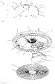
- the extractor hood 1 is designed as a freely suspended extractor hood 1, which can be fastened to the ceiling above a cooking island via three wire cables 27, for example.
- an extractor hood 1 has a housing device 2 with an upper housing cover 29, within which a processing section 3 is provided for processing vapors that have been sucked in.
- the treatment section 3 has a round cross-section 4, a round cross-section essentially transverse to the intake direction being considered here.
- the extractor hood shown here has an essentially dome-shaped design.
- the basic shape of the extractor hood 1 is essentially based on a hemisphere or a section of a sphere.
- the paid extractor hood 1 is designed for air recirculation, for which purpose the extractor hood 1 has an inlet opening 5 through which rising vapors are sucked into the extractor hood 1 . Furthermore, several outlet openings 6 are provided on the top of the extractor hood, through which the treated air is blown back into the kitchen.
- a decorative screen 20 is arranged in the area of the inlet opening 5 , by means of which one or more grease filters 21 are arranged in the inlet opening 5 . So by means of a in the Figures 1 and 2 said non-visible fan device 10 vapors through the grease filter 21, so that the interior of the extractor hood 1 is traversed by fat-free air as possible.
- FIG 3 a cross section through an exemplary embodiment of an extractor hood 1 according to the invention is shown purely schematically. It can be seen here that in this exemplary embodiment too, the extractor hood 1 has an essentially dome-shaped configuration, with the cross section 4 of the treatment section 3 being round.
- the treatment section 3 within the extractor hood 1 is divided into a lower inlet section 8 and an upper outlet section 9 by means of a separating device 7 .
- the separating device 7 is designed to be essentially flow-tight. However, in the separating device 7 in the exemplary embodiment shown, a passage 26 is provided, via which a fluidic connection between the lower inlet section 8 and the upper external blowing section 9 is provided.
- a fan device 10 is provided above this passage 26, by means of which air is sucked through the grease filter 21 into the lower inlet section 8 and then blown back into the kitchen via the upper blow-out section through the outlet openings 6.
- the flow of air within the extractor hood is indicated purely schematically by means of the dashed arrows.
- blower device 10 in the upper exhaust section 9 creates a substantially ring-shaped receiving space 11 between the separating device 7 and the outlet openings 6, in which, as will be explained in more detail below, several filter units 12 can be arranged, which are designed here as odor filters 28.
- the blower device 10 then blows the air, which has already been freed from fat components, into the upper blow-out section and forces the air through the filter units 12 through the outlet openings 6 back into the kitchen.
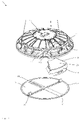
- FIG 4 is a purely schematic representation of an exemplary embodiment of an extractor hood 1 according to the invention in a perspective view from below, with the decorative panel 20 being shown removed from the inlet opening 5 together with the grease filters 21 in order to provide a view of the lower inlet section 8 and the separating device 7.
- a separating device 7 is provided within the processing section 3, which is basically designed to be flow-tight.
- a passage 26 is provided in the center here, via which air can be conveyed into the upper blow-out section 9 or into the annular receiving space 11 by means of the blower device 10 arranged above it.
- a recess 13 is provided in the separating device 7 , via which a user can easily reach the filter units 12 .
- the filter units 12 adapted to the annular receiving space 11 can be fed to the annular receiving space 11 via the recess 13 and then moved transversely to the radius of the processing section 3 into an otherwise inaccessible area 19 of the annular receiving space 11 .
- the recess 13 can be closed by means of a closure device 18 be so that the passage 26 is the only fluidic connection between the upper section 9 and the lower section 8 .
- the last filter unit 12 is inserted into the annular receiving space 11 together with the closure device 18 .
- this filter unit 12 and the closure device 18 are provided as a common structural unit, with the filter device 12 being screwed onto the closure unit 18 here.
- a driver device 14 is provided in the exemplary embodiment shown here, which here comprises a driver ring 15 or a driver disk 16 .
- This driver ring 15 is arranged radially on the outside in the annular receiving space 11 , with the filter units 12 also being displaced in the direction of rotation by rotating the driver ring 15 via the separating device 7 .
- a displacement of the filter units 12 can thus be achieved via the driver ring 15 or a driver disk 16, even if the filter units 12 themselves cannot be reached.
- figure 5 is the embodiment according to figure 4 shown in a perspective view from above, with the in figure 1 shown upper housing cover 29 is not shown in order to be able to look into the upper blow-out section 9 or the annular receiving space 11 from above.
- the recess 13 can be seen, via which filter units 12 can be supplied to the annular receiving space 11 and removed from it.
- This view also shows the closure device 18, which is designed as a common structural unit, together with the one with a filter unit 12.
- the inside of the decorative panel 20 is divided into four sections, in each of which a grease filter 21 is arranged.
- the decorative panel 20 also includes fastening tabs 30 , via which the decorative panel 20 engages in corresponding receptacles in the lower inlet section 8 of the processing section 3 .
- a lock 31 is provided.
- a filter unit 12 is shown in a purely schematic perspective view, which here comprises a filter frame 22 and a filter element 23 , the filter element 23 being designed here as an odor filter 28 .
- a filter unit 12 can be designed as a common structural unit with the closure device 18, with the filter frame 22 of the filter unit 12 being fixed on the closure device 18 or screwed to it.
- driver device 14 is shown purely schematically, which is designed here as a driver ring 15 or as a driver disk 16 .
- this driver device 14 or driver disk 15 rests on the separating device 7 in the upper blow-out section 9 in the installed state.
- the driver ring 15 is dimensioned in such a way that it lies in the outer region of the annular receiving space 12 .
- a fastening device 17 is provided for this purpose, which in the exemplary embodiment shown here comprises a fastening element 25 on the filter unit 12 or on the filter frame 22 and a fastening element 24 on the driver device 14 .
- hook-like structures are provided as fastening elements 25 on the filter units 12, which engage in fastening elements 24 designed as recesses in the driver ring.
- the filter units 12 When the filter units 12 are inserted into the annular receiving space 11 through the recess 13, they can also be displaced again by rotating the driver device 14 or the driver ring 15.
- filter units 12 When inserting, however, it is also possible for the filter units 12 to be pushed or pressed manually from the recess 13 transversely to the radius of the treatment section 3 into the annular receiving space 11 . Filter units 12 that have already been used are conveyed further by pushing in the following filter unit and can be moved into an otherwise inaccessible area 19 .
Landscapes
- Engineering & Computer Science (AREA)
- Chemical & Material Sciences (AREA)
- Combustion & Propulsion (AREA)
- Mechanical Engineering (AREA)
- General Engineering & Computer Science (AREA)
- Ventilation (AREA)
Applications Claiming Priority (1)
| Application Number | Priority Date | Filing Date | Title |
|---|---|---|---|
| DE102019101589.8A DE102019101589B4 (de) | 2019-01-23 | 2019-01-23 | Dunstabzugshaube und Verfahren zum Wechseln von Filtereinheiten |
Publications (2)
| Publication Number | Publication Date |
|---|---|
| EP3686496A1 EP3686496A1 (de) | 2020-07-29 |
| EP3686496B1 true EP3686496B1 (de) | 2022-06-22 |
Family
ID=68771468
Family Applications (1)
| Application Number | Title | Priority Date | Filing Date |
|---|---|---|---|
| EP19213481.5A Active EP3686496B1 (de) | 2019-01-23 | 2019-12-04 | Dunstabzugshaube und verfahren zum wechseln von filtereinheiten |
Country Status (4)
| Country | Link |
|---|---|
| EP (1) | EP3686496B1 (pl) |
| DE (1) | DE102019101589B4 (pl) |
| ES (1) | ES2922374T3 (pl) |
| PL (1) | PL3686496T3 (pl) |
Families Citing this family (4)
| Publication number | Priority date | Publication date | Assignee | Title |
|---|---|---|---|---|
| CN114165822A (zh) * | 2021-12-30 | 2022-03-11 | 佛山市淇特科技有限公司 | 一种中岛油烟机 |
| BE1030782B1 (de) * | 2022-08-16 | 2024-03-18 | Miele & Cie | Dunstabzugeinrichtung mit wenigstens einem Umluftadapter, Deckenlüftersystem und Verfahren zum Betreiben |
| EP4325125A3 (de) * | 2022-08-15 | 2024-05-29 | Miele & Cie. KG | Dunstabzugeinrichtung mit wenigstens einem umluftadapter, deckenlüftersystem und verfahren zum betreiben |
| DE102022123338A1 (de) * | 2022-09-13 | 2024-03-14 | Berbel Ablufttechnik Gmbh | Dunstabzug und Kombinationsgerät |
Family Cites Families (7)
| Publication number | Priority date | Publication date | Assignee | Title |
|---|---|---|---|---|
| CH637307A5 (fr) * | 1980-08-07 | 1983-07-29 | Pierre De Castella | Hotte d'epuration de fluides gazeux. |
| US5268012A (en) * | 1993-01-29 | 1993-12-07 | Jang Sun Sing | Fume extractor |
| DE102011001184B4 (de) * | 2011-03-10 | 2012-11-22 | Miele & Cie. Kg | Dunstabzugshaube für eine Herd, eine Kochstelle oder dergleichen |
| DE102012022571A1 (de) * | 2012-11-20 | 2014-05-22 | minEnergy GmbH | Dunstabzugshaube |
| ITUB20154759A1 (it) * | 2015-11-02 | 2017-05-02 | Falmec S P A | Cappa filtrante con filtri affacciati alla girante |
| DE102017100855B4 (de) * | 2017-01-18 | 2020-06-18 | Miele & Cie. Kg | Dunstabzugshaube |
| CN108592116A (zh) * | 2018-06-19 | 2018-09-28 | 广东美的厨房电器制造有限公司 | 吊灯烟机及用于该吊灯烟机的控制系统 |
-
2019
- 2019-01-23 DE DE102019101589.8A patent/DE102019101589B4/de active Active
- 2019-12-04 ES ES19213481T patent/ES2922374T3/es active Active
- 2019-12-04 PL PL19213481.5T patent/PL3686496T3/pl unknown
- 2019-12-04 EP EP19213481.5A patent/EP3686496B1/de active Active
Also Published As
| Publication number | Publication date |
|---|---|
| DE102019101589A1 (de) | 2020-07-23 |
| DE102019101589B4 (de) | 2021-02-11 |
| EP3686496A1 (de) | 2020-07-29 |
| ES2922374T3 (es) | 2022-09-14 |
| PL3686496T3 (pl) | 2022-09-05 |
Similar Documents
| Publication | Publication Date | Title |
|---|---|---|
| EP3686496B1 (de) | Dunstabzugshaube und verfahren zum wechseln von filtereinheiten | |
| EP0926449B2 (de) | Verfahren zum Entfeuchten eines Garraumes eines Dampfgargerätes sowie Vorrichtung hierfür | |
| DE102017223828A1 (de) | Dunstabzugsvorrichtung zum Abzug von Kochdünsten nach unten | |
| DE4039175A1 (de) | Filterbehaelter | |
| DE102011079793A1 (de) | Dunstabzugshaube | |
| WO2014079568A2 (de) | Dunstabzugshaube | |
| DE102013005921A1 (de) | Fluidisierungsapparat | |
| EP2857758B1 (de) | Dunstabzugsvorrichtung | |
| DE102012206254A1 (de) | Abdeckeinrichtung und Tischlüftereinrichtung | |
| EP3220060B1 (de) | Dunstabzugsvorrichtung | |
| EP3819549A1 (de) | Dunstabzugsvorrichtung für ein küchengerät | |
| EP2113650B1 (de) | Luftfiltergehäuse mit schwenkbarer Reinlufthaube | |
| EP3561392A1 (de) | Luftleitsystem | |
| DE102015103034A1 (de) | Absaugvorrichtung | |
| DE102005019957A1 (de) | Garofen | |
| EP3653940B1 (de) | Dunstabzugshaube | |
| EP3763431B1 (de) | Filtergerät | |
| EP2955450B1 (de) | Dunstabzugshaube | |
| BE1030832B1 (de) | Abzugsvorrichtung für ein Kochfeld und Kochfeld | |
| EP1180647A1 (de) | Dunstabzugshaube | |
| EP3108952A1 (de) | Luftreiniger | |
| EP3825613B1 (de) | Dunstabzugshaube | |
| EP2944883A1 (de) | Dunstabzugshaubeneinrichtung und verfahren | |
| DE2323229A1 (de) | Ueberwachungseinrichtung fuer die filteranordnung in dunstabzugshauben u. dgl | |
| DE102005013806A1 (de) | Dunstabzugshaube |
Legal Events
| Date | Code | Title | Description |
|---|---|---|---|
| PUAI | Public reference made under article 153(3) epc to a published international application that has entered the european phase |
Free format text: ORIGINAL CODE: 0009012 |
|
| STAA | Information on the status of an ep patent application or granted ep patent |
Free format text: STATUS: THE APPLICATION HAS BEEN PUBLISHED |
|
| AK | Designated contracting states |
Kind code of ref document: A1 Designated state(s): AL AT BE BG CH CY CZ DE DK EE ES FI FR GB GR HR HU IE IS IT LI LT LU LV MC MK MT NL NO PL PT RO RS SE SI SK SM TR |
|
| AX | Request for extension of the european patent |
Extension state: BA ME |
|
| STAA | Information on the status of an ep patent application or granted ep patent |
Free format text: STATUS: REQUEST FOR EXAMINATION WAS MADE |
|
| 17P | Request for examination filed |
Effective date: 20210129 |
|
| RBV | Designated contracting states (corrected) |
Designated state(s): AL AT BE BG CH CY CZ DE DK EE ES FI FR GB GR HR HU IE IS IT LI LT LU LV MC MK MT NL NO PL PT RO RS SE SI SK SM TR |
|
| GRAP | Despatch of communication of intention to grant a patent |
Free format text: ORIGINAL CODE: EPIDOSNIGR1 |
|
| STAA | Information on the status of an ep patent application or granted ep patent |
Free format text: STATUS: GRANT OF PATENT IS INTENDED |
|
| INTG | Intention to grant announced |
Effective date: 20220328 |
|
| GRAS | Grant fee paid |
Free format text: ORIGINAL CODE: EPIDOSNIGR3 |
|
| GRAA | (expected) grant |
Free format text: ORIGINAL CODE: 0009210 |
|
| STAA | Information on the status of an ep patent application or granted ep patent |
Free format text: STATUS: THE PATENT HAS BEEN GRANTED |
|
| AK | Designated contracting states |
Kind code of ref document: B1 Designated state(s): AL AT BE BG CH CY CZ DK EE ES FI FR GB GR HR HU IE IS IT LI LT LU LV MC MK MT NL NO PL PT RO RS SE SI SK SM TR |
|
| RBV | Designated contracting states (corrected) |
Designated state(s): AL AT BE BG CH CY CZ DK EE ES FI FR GB GR HR HU IE IS IT LI LT LU LV MC MK MT NL NO PL PT RO RS SE SI SK SM TR |
|
| REG | Reference to a national code |
Ref country code: DE Ref legal event code: R108 Ref country code: GB Ref legal event code: FG4D Free format text: NOT ENGLISH |
|
| REG | Reference to a national code |
Ref country code: CH Ref legal event code: EP |
|
| REG | Reference to a national code |
Ref country code: AT Ref legal event code: REF Ref document number: 1499993 Country of ref document: AT Kind code of ref document: T Effective date: 20220715 |
|
| REG | Reference to a national code |
Ref country code: IE Ref legal event code: FG4D Free format text: LANGUAGE OF EP DOCUMENT: GERMAN Ref country code: NL Ref legal event code: FP |
|
| REG | Reference to a national code |
Ref country code: ES Ref legal event code: FG2A Ref document number: 2922374 Country of ref document: ES Kind code of ref document: T3 Effective date: 20220914 |
|
| REG | Reference to a national code |
Ref country code: LT Ref legal event code: MG9D |
|
| PG25 | Lapsed in a contracting state [announced via postgrant information from national office to epo] |
Ref country code: SE Free format text: LAPSE BECAUSE OF FAILURE TO SUBMIT A TRANSLATION OF THE DESCRIPTION OR TO PAY THE FEE WITHIN THE PRESCRIBED TIME-LIMIT Effective date: 20220622 Ref country code: NO Free format text: LAPSE BECAUSE OF FAILURE TO SUBMIT A TRANSLATION OF THE DESCRIPTION OR TO PAY THE FEE WITHIN THE PRESCRIBED TIME-LIMIT Effective date: 20220922 Ref country code: LT Free format text: LAPSE BECAUSE OF FAILURE TO SUBMIT A TRANSLATION OF THE DESCRIPTION OR TO PAY THE FEE WITHIN THE PRESCRIBED TIME-LIMIT Effective date: 20220622 Ref country code: HR Free format text: LAPSE BECAUSE OF FAILURE TO SUBMIT A TRANSLATION OF THE DESCRIPTION OR TO PAY THE FEE WITHIN THE PRESCRIBED TIME-LIMIT Effective date: 20220622 Ref country code: GR Free format text: LAPSE BECAUSE OF FAILURE TO SUBMIT A TRANSLATION OF THE DESCRIPTION OR TO PAY THE FEE WITHIN THE PRESCRIBED TIME-LIMIT Effective date: 20220923 Ref country code: FI Free format text: LAPSE BECAUSE OF FAILURE TO SUBMIT A TRANSLATION OF THE DESCRIPTION OR TO PAY THE FEE WITHIN THE PRESCRIBED TIME-LIMIT Effective date: 20220622 Ref country code: BG Free format text: LAPSE BECAUSE OF FAILURE TO SUBMIT A TRANSLATION OF THE DESCRIPTION OR TO PAY THE FEE WITHIN THE PRESCRIBED TIME-LIMIT Effective date: 20220922 |
|
| PG25 | Lapsed in a contracting state [announced via postgrant information from national office to epo] |
Ref country code: RS Free format text: LAPSE BECAUSE OF FAILURE TO SUBMIT A TRANSLATION OF THE DESCRIPTION OR TO PAY THE FEE WITHIN THE PRESCRIBED TIME-LIMIT Effective date: 20220622 Ref country code: LV Free format text: LAPSE BECAUSE OF FAILURE TO SUBMIT A TRANSLATION OF THE DESCRIPTION OR TO PAY THE FEE WITHIN THE PRESCRIBED TIME-LIMIT Effective date: 20220622 |
|
| PG25 | Lapsed in a contracting state [announced via postgrant information from national office to epo] |
Ref country code: SM Free format text: LAPSE BECAUSE OF FAILURE TO SUBMIT A TRANSLATION OF THE DESCRIPTION OR TO PAY THE FEE WITHIN THE PRESCRIBED TIME-LIMIT Effective date: 20220622 Ref country code: SK Free format text: LAPSE BECAUSE OF FAILURE TO SUBMIT A TRANSLATION OF THE DESCRIPTION OR TO PAY THE FEE WITHIN THE PRESCRIBED TIME-LIMIT Effective date: 20220622 Ref country code: RO Free format text: LAPSE BECAUSE OF FAILURE TO SUBMIT A TRANSLATION OF THE DESCRIPTION OR TO PAY THE FEE WITHIN THE PRESCRIBED TIME-LIMIT Effective date: 20220622 Ref country code: PT Free format text: LAPSE BECAUSE OF FAILURE TO SUBMIT A TRANSLATION OF THE DESCRIPTION OR TO PAY THE FEE WITHIN THE PRESCRIBED TIME-LIMIT Effective date: 20221024 Ref country code: EE Free format text: LAPSE BECAUSE OF FAILURE TO SUBMIT A TRANSLATION OF THE DESCRIPTION OR TO PAY THE FEE WITHIN THE PRESCRIBED TIME-LIMIT Effective date: 20220622 Ref country code: CZ Free format text: LAPSE BECAUSE OF FAILURE TO SUBMIT A TRANSLATION OF THE DESCRIPTION OR TO PAY THE FEE WITHIN THE PRESCRIBED TIME-LIMIT Effective date: 20220622 |
|
| PG25 | Lapsed in a contracting state [announced via postgrant information from national office to epo] |
Ref country code: IS Free format text: LAPSE BECAUSE OF FAILURE TO SUBMIT A TRANSLATION OF THE DESCRIPTION OR TO PAY THE FEE WITHIN THE PRESCRIBED TIME-LIMIT Effective date: 20221022 |
|
| PG25 | Lapsed in a contracting state [announced via postgrant information from national office to epo] |
Ref country code: AL Free format text: LAPSE BECAUSE OF FAILURE TO SUBMIT A TRANSLATION OF THE DESCRIPTION OR TO PAY THE FEE WITHIN THE PRESCRIBED TIME-LIMIT Effective date: 20220622 |
|
| PG25 | Lapsed in a contracting state [announced via postgrant information from national office to epo] |
Ref country code: DK Free format text: LAPSE BECAUSE OF FAILURE TO SUBMIT A TRANSLATION OF THE DESCRIPTION OR TO PAY THE FEE WITHIN THE PRESCRIBED TIME-LIMIT Effective date: 20220622 |
|
| PLBE | No opposition filed within time limit |
Free format text: ORIGINAL CODE: 0009261 |
|
| STAA | Information on the status of an ep patent application or granted ep patent |
Free format text: STATUS: NO OPPOSITION FILED WITHIN TIME LIMIT |
|
| 26N | No opposition filed |
Effective date: 20230323 |
|
| P01 | Opt-out of the competence of the unified patent court (upc) registered |
Effective date: 20230528 |
|
| REG | Reference to a national code |
Ref country code: CH Ref legal event code: PL |
|
| REG | Reference to a national code |
Ref country code: BE Ref legal event code: MM Effective date: 20221231 |
|
| PG25 | Lapsed in a contracting state [announced via postgrant information from national office to epo] |
Ref country code: SI Free format text: LAPSE BECAUSE OF FAILURE TO SUBMIT A TRANSLATION OF THE DESCRIPTION OR TO PAY THE FEE WITHIN THE PRESCRIBED TIME-LIMIT Effective date: 20220622 Ref country code: LU Free format text: LAPSE BECAUSE OF NON-PAYMENT OF DUE FEES Effective date: 20221204 |
|
| PG25 | Lapsed in a contracting state [announced via postgrant information from national office to epo] |
Ref country code: LI Free format text: LAPSE BECAUSE OF NON-PAYMENT OF DUE FEES Effective date: 20221231 Ref country code: IE Free format text: LAPSE BECAUSE OF NON-PAYMENT OF DUE FEES Effective date: 20221204 Ref country code: CH Free format text: LAPSE BECAUSE OF NON-PAYMENT OF DUE FEES Effective date: 20221231 |
|
| PG25 | Lapsed in a contracting state [announced via postgrant information from national office to epo] |
Ref country code: BE Free format text: LAPSE BECAUSE OF NON-PAYMENT OF DUE FEES Effective date: 20221231 |
|
| PG25 | Lapsed in a contracting state [announced via postgrant information from national office to epo] |
Ref country code: HU Free format text: LAPSE BECAUSE OF FAILURE TO SUBMIT A TRANSLATION OF THE DESCRIPTION OR TO PAY THE FEE WITHIN THE PRESCRIBED TIME-LIMIT; INVALID AB INITIO Effective date: 20191204 |
|
| PG25 | Lapsed in a contracting state [announced via postgrant information from national office to epo] |
Ref country code: CY Free format text: LAPSE BECAUSE OF FAILURE TO SUBMIT A TRANSLATION OF THE DESCRIPTION OR TO PAY THE FEE WITHIN THE PRESCRIBED TIME-LIMIT Effective date: 20220622 |
|
| PG25 | Lapsed in a contracting state [announced via postgrant information from national office to epo] |
Ref country code: MK Free format text: LAPSE BECAUSE OF FAILURE TO SUBMIT A TRANSLATION OF THE DESCRIPTION OR TO PAY THE FEE WITHIN THE PRESCRIBED TIME-LIMIT Effective date: 20220622 |
|
| PG25 | Lapsed in a contracting state [announced via postgrant information from national office to epo] |
Ref country code: MC Free format text: LAPSE BECAUSE OF FAILURE TO SUBMIT A TRANSLATION OF THE DESCRIPTION OR TO PAY THE FEE WITHIN THE PRESCRIBED TIME-LIMIT Effective date: 20220622 |
|
| PG25 | Lapsed in a contracting state [announced via postgrant information from national office to epo] |
Ref country code: MC Free format text: LAPSE BECAUSE OF FAILURE TO SUBMIT A TRANSLATION OF THE DESCRIPTION OR TO PAY THE FEE WITHIN THE PRESCRIBED TIME-LIMIT Effective date: 20220622 |
|
| PG25 | Lapsed in a contracting state [announced via postgrant information from national office to epo] |
Ref country code: MT Free format text: LAPSE BECAUSE OF FAILURE TO SUBMIT A TRANSLATION OF THE DESCRIPTION OR TO PAY THE FEE WITHIN THE PRESCRIBED TIME-LIMIT Effective date: 20220622 |
|
| PG25 | Lapsed in a contracting state [announced via postgrant information from national office to epo] |
Ref country code: BG Free format text: LAPSE BECAUSE OF FAILURE TO SUBMIT A TRANSLATION OF THE DESCRIPTION OR TO PAY THE FEE WITHIN THE PRESCRIBED TIME-LIMIT Effective date: 20220622 |
|
| PG25 | Lapsed in a contracting state [announced via postgrant information from national office to epo] |
Ref country code: BG Free format text: LAPSE BECAUSE OF FAILURE TO SUBMIT A TRANSLATION OF THE DESCRIPTION OR TO PAY THE FEE WITHIN THE PRESCRIBED TIME-LIMIT Effective date: 20220622 |
|
| PGFP | Annual fee paid to national office [announced via postgrant information from national office to epo] |
Ref country code: GB Payment date: 20251223 Year of fee payment: 7 |
|
| PGFP | Annual fee paid to national office [announced via postgrant information from national office to epo] |
Ref country code: IT Payment date: 20251218 Year of fee payment: 7 |
|
| PGFP | Annual fee paid to national office [announced via postgrant information from national office to epo] |
Ref country code: FR Payment date: 20251230 Year of fee payment: 7 Ref country code: NL Payment date: 20251222 Year of fee payment: 7 |
|
| PGFP | Annual fee paid to national office [announced via postgrant information from national office to epo] |
Ref country code: TR Payment date: 20251120 Year of fee payment: 7 |
|
| PGFP | Annual fee paid to national office [announced via postgrant information from national office to epo] |
Ref country code: PL Payment date: 20251126 Year of fee payment: 7 |
|
| REG | Reference to a national code |
Ref country code: AT Ref legal event code: MM01 Ref document number: 1499993 Country of ref document: AT Kind code of ref document: T Effective date: 20241204 |
|
| PGFP | Annual fee paid to national office [announced via postgrant information from national office to epo] |
Ref country code: ES Payment date: 20260112 Year of fee payment: 7 |
|
| PG25 | Lapsed in a contracting state [announced via postgrant information from national office to epo] |
Ref country code: AT Free format text: LAPSE BECAUSE OF NON-PAYMENT OF DUE FEES Effective date: 20241204 |
|
| PGFP | Annual fee paid to national office [announced via postgrant information from national office to epo] |
Ref country code: AT Payment date: 20260410 Year of fee payment: 5 |