EP3686496B1 - Vapour hood and method for changing filter units - Google Patents
Vapour hood and method for changing filter units Download PDFInfo
- Publication number
- EP3686496B1 EP3686496B1 EP19213481.5A EP19213481A EP3686496B1 EP 3686496 B1 EP3686496 B1 EP 3686496B1 EP 19213481 A EP19213481 A EP 19213481A EP 3686496 B1 EP3686496 B1 EP 3686496B1
- Authority
- EP
- European Patent Office
- Prior art keywords
- driver
- extractor hood
- filter unit
- filter
- separating device
- Prior art date
- Legal status (The legal status is an assumption and is not a legal conclusion. Google has not performed a legal analysis and makes no representation as to the accuracy of the status listed.)
- Active
Links
- 238000000034 method Methods 0.000 title claims description 15
- 238000007664 blowing Methods 0.000 claims description 4
- 238000003825 pressing Methods 0.000 claims description 4
- 239000004519 grease Substances 0.000 description 16
- 235000019645 odor Nutrition 0.000 description 11
- 230000000630 rising effect Effects 0.000 description 5
- OKTJSMMVPCPJKN-UHFFFAOYSA-N Carbon Chemical compound [C] OKTJSMMVPCPJKN-UHFFFAOYSA-N 0.000 description 4
- 238000006073 displacement reaction Methods 0.000 description 4
- 238000010411 cooking Methods 0.000 description 3
- 238000011161 development Methods 0.000 description 3
- 230000018109 developmental process Effects 0.000 description 3
- 230000004308 accommodation Effects 0.000 description 2
- 239000000853 adhesive Substances 0.000 description 2
- 230000001070 adhesive effect Effects 0.000 description 2
- 230000002349 favourable effect Effects 0.000 description 2
- 239000003517 fume Substances 0.000 description 2
- 238000004140 cleaning Methods 0.000 description 1
- 230000001419 dependent effect Effects 0.000 description 1
- 230000000694 effects Effects 0.000 description 1
- 235000013861 fat-free Nutrition 0.000 description 1
- 238000001914 filtration Methods 0.000 description 1
- 230000003472 neutralizing effect Effects 0.000 description 1
- 238000002360 preparation method Methods 0.000 description 1
Images


Classifications
-
- F—MECHANICAL ENGINEERING; LIGHTING; HEATING; WEAPONS; BLASTING
- F24—HEATING; RANGES; VENTILATING
- F24C—DOMESTIC STOVES OR RANGES ; DETAILS OF DOMESTIC STOVES OR RANGES, OF GENERAL APPLICATION
- F24C15/00—Details
- F24C15/20—Removing cooking fumes
- F24C15/2035—Arrangement or mounting of filters
Definitions
- the present invention relates to an extractor hood comprising at least one housing device with at least one treatment section with a round cross section.
- the housing or the treatment section comprises at least one inlet opening for sucking in vapors and at least one outlet opening for blowing out treated air.
- the present invention also relates to a method for changing filter units in such an extractor hood.
- Extractor hoods are often used in kitchens above hobs in order to suck in the vapors that rise during cooking and in particular to free them from fat components.
- the cleaned air is then either discharged from the kitchen as exhaust air or blown back into the kitchen in a recirculation mode.
- Extractor hoods for air recirculation are known from the publication EP 2 498 006 A1 and from the pamphlet DE 10 2017 100 855 A1 .
- Odor pollution in recirculation mode can be achieved, for example, by means of odor-absorbing and/or neutralizing filters, such as activated carbon filters.
- filters such as activated carbon filters.
- the air flow through the fan is directed or pressed through such a filter before leaving the extractor hood.
- the extractor hood comprises at least one housing device with at least one treatment section with at least one round cross section.
- the housing device or the treatment section has at least one inlet opening for sucking in vapors and at least one outlet opening for blowing out treated air.
- at least one essentially flow-tight separating device is arranged in the processing section, which divides the processing section into at least one lower inlet section with the inlet opening and at least one upper blow-out section with the outlet opening.
- An essentially flow-tight separating device is designed in such a way that a maximum of 10 percent of the air flow to which it is exposed bypasses the separating device as leakage air flow.
- At least one passage is provided in the separating device as a connection between the lower inlet section and the upper blow-out section, with at least one fan device being arranged on the passage, which draws in air from the inlet opening and blows it out in the direction of the outlet opening.
- at least one essentially ring-shaped receiving space for accommodating at least two filter units, which is accessible at least in sections via at least one recess in the separating device in order to remove the filter units through this recess and/or use.
- the term essentially ring-shaped is to be understood in such a way that the figurative-technical term ring is not only reduced to a circular ring, but also includes other basic ring shapes. Neither is the relationship between the distance from the inside of the ring to the center and the distance from the outside of the ring to the center defined.
- the extractor hood according to the invention is in particular an extractor hood which is suitable or designed exclusively or also alternatively for recirculation mode.
- the filter units which can be inserted into the essentially ring-shaped receiving space, are preferably designed as odor filters and such odor filters, for example activated carbon filters, remove odors from the air that has already been cleaned by grease filters, which is particularly important when the air is blown back into the kitchen during recirculation mode is advantageous.
- the housing device or the processing section has a round cross section.
- the processing section preferably has a substantially cylindrical shape, at least in sections.
- a dome-shaped configuration of the housing device or the extractor hood or the processing section is also preferred.
- an essentially cylindrical shape can also include conical or asymmetrical spatial bodies.
- the extractor hood according to the invention is preferably designed as a freely suspended extractor hood, which is arranged, for example, over a cooking island. In this case, an attachment of the extractor hood z. B. with wire ropes or the like on the ceiling.
- blower device is arranged at the passage means in particular that the blower device is directly or indirectly operatively connected to the opening or the passage, so that the blower device can convey air from the inlet opening to the outlet opening.
- the blower device is positioned above the passage on or on the separating device and is preferably fastened to the separating device.
- the annular receiving space is preferably delimited by the housing device in the blow-out section and the blower device arranged in the blow-out section.
- the annular receiving space preferably extends around the blower device.
- the blower device Since the blower device is arranged in the upper exhaust section, the blower device preferably sucks rising fumes through a grease filter arranged in or at the inlet opening into the extractor hood or into the preparation section and forces the air, which has already been cleaned of grease components, through the air that is arranged in the annular receiving space Filter units, which are designed in particular as odor filters. In this way, a particularly advantageous air flow is achieved by means of the blower device.
- the recess in the separating device is preferably provided in such a way that the filter units movable in the circumferential direction in the receiving space can be inserted into and removed from the annular receiving space substantially transversely to the radius of the annular receiving space, i.e. in the axial direction.
- the specification essentially transverse to the radius is not limited to a strict geometric movement perpendicular to the radius, but includes different orientations in a common handling space.
- the tolerance includes a deviation of up to 60°.
- the recess in the separating device via which access to the annular receiving space is provided, can be closed so that during normal operation of the extractor hood the entire air flow is reached through the passage in the separating device via the blower device.
- the recess is then only opened when a filter unit is to be removed from the annular receiving space or when a filter unit is to be changed.
- the recess can also be closed again by means of a closure device.
- At least one grease filter is preferably provided on or in the inlet opening.
- the rising vapor is freed from grease components.
- Such a grease filter can preferably be accommodated in a visually appealing decorative panel, with the removal of the decorative panel preferably simultaneously removing the grease filter or filters so that they can be easily cleaned or replaced.
- the extractor hood according to the invention offers many advantages.
- a significant advantage is that the separating device forms an upper and a lower section in the processing section, so that the processing section is divided into a suction side and a pressure side for the blower device.
- the fan sucks rising fumes through the grease filter and then pushes the sucked air through the other filter units, in particular through the odor filter. This results in a particularly favorable flow behavior reached.
- the configuration of the upper blow-out section as an annular receiving space with the recess for removing and inserting filter units ensures particularly favorable accessibility to the filter units.
- At least one driver device is provided in the upper blow-out section in order to displace the filter units within the annular receiving space, in particular to move them from an inaccessible area of the annular receiving space to the recess.
- the driver device is provided to transport inaccessible filter units to the recess for removing the filter units from the annular receiving space.
- the shifting of the filter units by means of the driver device can be motorized or achieved automatically and/or manually, depending on the configuration.
- the driver device particularly preferably comprises at least one driver ring and/or at least one driver disk.
- a driver disk or a driver ring can be arranged in particular on the outer edge of the receiving space or radially on the outside in the receiving space.
- the filter units preferably come into operative connection with the driver ring or the driver disk, so that a displacement of the filter units is brought about by the movement of the driver ring or the driver disk.
- the driver ring and/or the driver disk is/are preferably arranged so as to be rotatable in the receiving space.
- the filter units can be shifted.
- the driver ring and/or the driver disk is rotatably accommodated at least in sections on the separating device.
- the drive ring and / or the drive plate z. B. simply rest on the separator.
- other types of recording can also be used appropriately.
- the driver ring and/or the driver disk can be accommodated on the separating device via a rail system or can include other sliding aids or sliding elements, whereby a shifting of the driver ring or the driver disk on the separating device is facilitated.
- the driver device and/or at least one filter unit preferably comprises at least one fastening device.
- contact is provided between the driver device and the filter unit by means of such a fastening device, which is preferably designed to correspond between the driver device and the filter unit.
- a fastening device which is preferably designed to correspond between the driver device and the filter unit.
- Such a fastening device or a fastening between the filter unit and driver device can be achieved, for example, as a hook, driver or other fastening element with corresponding recesses.
- An adhesive connection in particular a reusable adhesive connection such as Velcro or a corrugated ring or the like can also be used as the connection between the driver device and the filter units.
- At least one preferably removable closure device is provided for closing the recess in the separating device.
- a separating device is provided that is fluidically tight except for the passage in the separating device.
- At least one filter unit is arranged on the closure device.
- at least one filter unit and the closure device is provided as a common structural unit, so that, depending on the configuration, the z. B. the last filter unit is used together with the closure device in the annular receiving space.
- the method according to the invention is suitable for changing filter units from the ring-shaped receiving space of an extractor hood, as has been described above. At least one filter unit is removed from the exception space through the recess in the separating device.
- the method according to the invention also offers the advantages already described above.
- At least one filter unit is shifted within the accommodation space to the removal device in the separating device by moving the driver device in order to remove the filter unit.
- the method described here describes the removal of a filter unit from the receiving space of an extractor hood according to the invention.
- the procedure can be carried out in reverse order.
- a filter unit is inserted into the receiving space through the recess in the separating device.
- the filter unit is then moved away from the recess by moving the driver device.
- a filter unit when inserting a filter unit, it can also be moved manually out of the area of the recess in the separating device.
- a filter unit when removing the filter, a filter unit can preferably be moved only in sections by means of the driver device until it can be reached by hand and can then also be pulled to the recess by hand.
- the driver device can preferably be motorized and/or manually operated.
- the recess in the separating device is preferably released by removing the closure device and/or closed by inserting the closure device.
- At least one filter unit is removed and/or inserted together with the closure device. This is possible in particular when at least one filter unit and the closure device form a common structural unit. In particular, this also means that at least one filter unit can be arranged in the area of the recess.
- the filter unit is inserted through the recess in the separating device into the annular receiving space, with the filter unit being displaced within the receiving space away from the recess by pressing against the filter unit.
- a filter unit can be moved away from the recess into an otherwise inaccessible area of the receiving space.
- the previously inserted filter units can, depending on the design, be conveyed further by means of the newly inserted filter unit if they are not also displaced by means of the driver device.
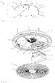
- the extractor hood 1 is designed as a freely suspended extractor hood 1, which can be fastened to the ceiling above a cooking island via three wire cables 27, for example.
- an extractor hood 1 has a housing device 2 with an upper housing cover 29, within which a processing section 3 is provided for processing vapors that have been sucked in.
- the treatment section 3 has a round cross-section 4, a round cross-section essentially transverse to the intake direction being considered here.
- the extractor hood shown here has an essentially dome-shaped design.
- the basic shape of the extractor hood 1 is essentially based on a hemisphere or a section of a sphere.
- the paid extractor hood 1 is designed for air recirculation, for which purpose the extractor hood 1 has an inlet opening 5 through which rising vapors are sucked into the extractor hood 1 . Furthermore, several outlet openings 6 are provided on the top of the extractor hood, through which the treated air is blown back into the kitchen.
- a decorative screen 20 is arranged in the area of the inlet opening 5 , by means of which one or more grease filters 21 are arranged in the inlet opening 5 . So by means of a in the Figures 1 and 2 said non-visible fan device 10 vapors through the grease filter 21, so that the interior of the extractor hood 1 is traversed by fat-free air as possible.
- FIG 3 a cross section through an exemplary embodiment of an extractor hood 1 according to the invention is shown purely schematically. It can be seen here that in this exemplary embodiment too, the extractor hood 1 has an essentially dome-shaped configuration, with the cross section 4 of the treatment section 3 being round.
- the treatment section 3 within the extractor hood 1 is divided into a lower inlet section 8 and an upper outlet section 9 by means of a separating device 7 .
- the separating device 7 is designed to be essentially flow-tight. However, in the separating device 7 in the exemplary embodiment shown, a passage 26 is provided, via which a fluidic connection between the lower inlet section 8 and the upper external blowing section 9 is provided.
- a fan device 10 is provided above this passage 26, by means of which air is sucked through the grease filter 21 into the lower inlet section 8 and then blown back into the kitchen via the upper blow-out section through the outlet openings 6.
- the flow of air within the extractor hood is indicated purely schematically by means of the dashed arrows.
- blower device 10 in the upper exhaust section 9 creates a substantially ring-shaped receiving space 11 between the separating device 7 and the outlet openings 6, in which, as will be explained in more detail below, several filter units 12 can be arranged, which are designed here as odor filters 28.
- the blower device 10 then blows the air, which has already been freed from fat components, into the upper blow-out section and forces the air through the filter units 12 through the outlet openings 6 back into the kitchen.
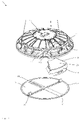
- FIG 4 is a purely schematic representation of an exemplary embodiment of an extractor hood 1 according to the invention in a perspective view from below, with the decorative panel 20 being shown removed from the inlet opening 5 together with the grease filters 21 in order to provide a view of the lower inlet section 8 and the separating device 7.
- a separating device 7 is provided within the processing section 3, which is basically designed to be flow-tight.
- a passage 26 is provided in the center here, via which air can be conveyed into the upper blow-out section 9 or into the annular receiving space 11 by means of the blower device 10 arranged above it.
- a recess 13 is provided in the separating device 7 , via which a user can easily reach the filter units 12 .
- the filter units 12 adapted to the annular receiving space 11 can be fed to the annular receiving space 11 via the recess 13 and then moved transversely to the radius of the processing section 3 into an otherwise inaccessible area 19 of the annular receiving space 11 .
- the recess 13 can be closed by means of a closure device 18 be so that the passage 26 is the only fluidic connection between the upper section 9 and the lower section 8 .
- the last filter unit 12 is inserted into the annular receiving space 11 together with the closure device 18 .
- this filter unit 12 and the closure device 18 are provided as a common structural unit, with the filter device 12 being screwed onto the closure unit 18 here.
- a driver device 14 is provided in the exemplary embodiment shown here, which here comprises a driver ring 15 or a driver disk 16 .
- This driver ring 15 is arranged radially on the outside in the annular receiving space 11 , with the filter units 12 also being displaced in the direction of rotation by rotating the driver ring 15 via the separating device 7 .
- a displacement of the filter units 12 can thus be achieved via the driver ring 15 or a driver disk 16, even if the filter units 12 themselves cannot be reached.
- figure 5 is the embodiment according to figure 4 shown in a perspective view from above, with the in figure 1 shown upper housing cover 29 is not shown in order to be able to look into the upper blow-out section 9 or the annular receiving space 11 from above.
- the recess 13 can be seen, via which filter units 12 can be supplied to the annular receiving space 11 and removed from it.
- This view also shows the closure device 18, which is designed as a common structural unit, together with the one with a filter unit 12.
- the inside of the decorative panel 20 is divided into four sections, in each of which a grease filter 21 is arranged.
- the decorative panel 20 also includes fastening tabs 30 , via which the decorative panel 20 engages in corresponding receptacles in the lower inlet section 8 of the processing section 3 .
- a lock 31 is provided.
- a filter unit 12 is shown in a purely schematic perspective view, which here comprises a filter frame 22 and a filter element 23 , the filter element 23 being designed here as an odor filter 28 .
- a filter unit 12 can be designed as a common structural unit with the closure device 18, with the filter frame 22 of the filter unit 12 being fixed on the closure device 18 or screwed to it.
- driver device 14 is shown purely schematically, which is designed here as a driver ring 15 or as a driver disk 16 .
- this driver device 14 or driver disk 15 rests on the separating device 7 in the upper blow-out section 9 in the installed state.
- the driver ring 15 is dimensioned in such a way that it lies in the outer region of the annular receiving space 12 .
- a fastening device 17 is provided for this purpose, which in the exemplary embodiment shown here comprises a fastening element 25 on the filter unit 12 or on the filter frame 22 and a fastening element 24 on the driver device 14 .
- hook-like structures are provided as fastening elements 25 on the filter units 12, which engage in fastening elements 24 designed as recesses in the driver ring.
- the filter units 12 When the filter units 12 are inserted into the annular receiving space 11 through the recess 13, they can also be displaced again by rotating the driver device 14 or the driver ring 15.
- filter units 12 When inserting, however, it is also possible for the filter units 12 to be pushed or pressed manually from the recess 13 transversely to the radius of the treatment section 3 into the annular receiving space 11 . Filter units 12 that have already been used are conveyed further by pushing in the following filter unit and can be moved into an otherwise inaccessible area 19 .
Landscapes
- Engineering & Computer Science (AREA)
- Chemical & Material Sciences (AREA)
- Combustion & Propulsion (AREA)
- Mechanical Engineering (AREA)
- General Engineering & Computer Science (AREA)
- Ventilation (AREA)
Description
Die vorliegende Erfindung betrifft eine Dunstabzugshaube umfassend wenigstens eine Gehäuseeinrichtung mit wenigstens einem Aufbereitungsabschnitt mit einem runden Querschnitt. Dabei umfasst das Gehäuse bzw. der Aufbereitungsabschnitt wenigstens eine Einlassöffnung zum Einsaugen von Wrasen und wenigstens eine Auslassöffnung zum Ausblasen von aufbereiteter Luft. Die vorliegende Erfindung betrifft zudem ein Verfahren zum Wechseln von Filtereinheiten bei einer solchen Dunstabzugshaube.The present invention relates to an extractor hood comprising at least one housing device with at least one treatment section with a round cross section. In this case, the housing or the treatment section comprises at least one inlet opening for sucking in vapors and at least one outlet opening for blowing out treated air. The present invention also relates to a method for changing filter units in such an extractor hood.
Dunstabzugshauben werden häufig in Küchen oberhalb von Kochfeldern eingesetzt, um den beim Kochen aufsteigenden Wrasen einzusaugen und diesen insbesondere von Fettbestandteilen zu befreien. Die gereinigte Luft wird dann entweder als Abluft aus der Küche abgeführt oder in einem Umluftbetrieb zurück in die Küche geblasen.Extractor hoods are often used in kitchens above hobs in order to suck in the vapors that rise during cooking and in particular to free them from fat components. The cleaned air is then either discharged from the kitchen as exhaust air or blown back into the kitchen in a recirculation mode.
Um den aufsteigenden Wrasen von Fettbestandteilen zu befreien, wird dieser in der Regel mittels eines Gebläses durch einen Fettfilter in die Dunstabzugshaube eingesaugt und dann entweder über eine geeignete Luftfortführung nach außen abgeleitet oder im Umluftbetrieb zurück in die Küche geführt. Insbesondere bei Dunstabzugshauben, welche im Umluftbetrieb verwendet werden, ist dabei oft neben der Befreiung von Fettbestandteilen auch eine Geruchsfilterung gewünscht. Dunstabzugshauben für den Umluftbetrieb sind bekannt aus der Druckschrift
Eine Geruchsbelastung im Umluftbetrieb kann beispielsweise über geruchsaufnehmende und/oder neutralisierende Filter, beispielsweise Aktivkohlefilter, erreicht werden. Dazu wird der Luftstrom durch das Gebläse vor dem Verlassen der Dunstabzugshaube durch einen solchen Filter geleitet bzw. gedrückt.Odor pollution in recirculation mode can be achieved, for example, by means of odor-absorbing and/or neutralizing filters, such as activated carbon filters. For this purpose, the air flow through the fan is directed or pressed through such a filter before leaving the extractor hood.
Problematisch bei allen Dunstabzugshauben ist in der Regel jedoch der Platzbedarf insbesondere für solche zusätzlichen Filter. Es kommt einem Benutzer nämlich nicht nur auf eine zufriedenstellende Funktionsweise der Dunstabzugshaube, sondern auch auf ein ansprechendes Design an. Hierdurch wird das zur Verfügung stehende Platzangebot oft sehr reduziert. Insbesondere Dunstabzugshauben mit einem runden oder rundlichen Querschnitt bzw. Gehäuse, wie sie aus der Druckschrift
Es ist daher die Aufgabe der vorliegenden Erfindung eine Dunstabzugshaube mit einem runden Querschnitt zur Verfügung zu stellen, bei welcher die Filter zur Geruchsreduktion besser zugänglich sind.It is therefore the object of the present invention to provide an extractor hood with a round cross section, in which the filters for odor reduction are more accessible.
Diese Aufgabe wird gelöst durch eine Dunstabzugshaube mit den Merkmalen des Anspruchs 1 und durch ein Verfahren zum Wechseln von Filtereinheiten mit den Merkmalen des Anspruchs 9. Bevorzugte Weiterbildungen der Erfindung sind Gegenstand der Unteransprüche. Weitere Vorteile und Merkmale der Erfindung ergeben sich aus den Ausführungsbeispielen.This object is achieved by an extractor hood having the features of
Die erfindungsgemäße Dunstabzugshaube umfasst wenigstens eine Gehäuseeinrichtung mit wenigstens einem Aufbereitungsabschnitt mit wenigstens einem runden Querschnitt. Dabei weist die Gehäuseeinrichtung bzw. der Aufbereitungsabschnitt wenigstens eine Einlassöffnung zum Einsaugen von Wrasen und wenigstens eine Auslassöffnung zum Ausblasen von aufbereiteter Luft auf. Erfindungsgemäß ist in dem Aufbereitungsabschnitt wenigstens eine im Wesentlichen strömungsdichte Trenneinrichtung angeordnet, welche den Aufbereitungsabschnitt in wenigstens einen unteren Einlassabschnitt mit der Einlassöffnung und wenigstens einen oberen Ausblasabschnitt mit der Auslassöffnung unterteilt. Eine im Wesentlichen strömungsdichte Trenneinrichtung ist derart ausgeführt, dass von dem Luftstrom, welchem sie ausgesetzt ist, maximal 10 Prozent als Fehlluftstrom die Trenneinrichtung umgeht. Dabei ist in der Trenneinrichtung wenigstens ein Durchlass als Verbindung zwischen dem unteren Einlassabschnitt und dem oberen Ausblasabschnitt vorgesehen, wobei an dem Durchlass wenigstens eine Gebläseeinrichtung angeordnet ist, welche Luft von der Einlassöffnung ansaugt und diese in Richtung der Auslassöffnung ausbläst. Weiterhin ist in dem oberen Abschnitt des Aufbereitungsabschnitts zwischen der Trenneinrichtung und der Auslassöffnung wenigstens ein im Wesentlichen ringförmiger Aufnahmeraum zur Aufnahme von wenigstens zwei Filtereinheiten gebildet, welcher über wenigstens eine Ausnehmung in der Trenneinrichtung wenigstens abschnittsweise zugänglich ist, um die Filtereinheiten durch diese Ausnehmung hindurch zu entnehmen und/oder einzusetzen. Der Begriff im Wesentlichen ringförmig ist derart zu verstehen, dass der figürlich-technische Begriff Ring nicht nur auf einen kreisrunden Ring reduziert wird, sondern auch andere Ringgrundformen eingeschlossen sind. Ebenso wenig ist das Verhältnis zwischen dem Abstand der Innenseite des Rings zum Mittelpunkt und dem Abstand der Außenseite des Rings zum Mittelpunkt definiert.The extractor hood according to the invention comprises at least one housing device with at least one treatment section with at least one round cross section. The housing device or the treatment section has at least one inlet opening for sucking in vapors and at least one outlet opening for blowing out treated air. According to the invention, at least one essentially flow-tight separating device is arranged in the processing section, which divides the processing section into at least one lower inlet section with the inlet opening and at least one upper blow-out section with the outlet opening. An essentially flow-tight separating device is designed in such a way that a maximum of 10 percent of the air flow to which it is exposed bypasses the separating device as leakage air flow. At least one passage is provided in the separating device as a connection between the lower inlet section and the upper blow-out section, with at least one fan device being arranged on the passage, which draws in air from the inlet opening and blows it out in the direction of the outlet opening. Furthermore, in the upper section of the processing section between the separating device and the outlet opening there is at least one essentially ring-shaped receiving space for accommodating at least two filter units, which is accessible at least in sections via at least one recess in the separating device in order to remove the filter units through this recess and/or use. The term essentially ring-shaped is to be understood in such a way that the figurative-technical term ring is not only reduced to a circular ring, but also includes other basic ring shapes. Neither is the relationship between the distance from the inside of the ring to the center and the distance from the outside of the ring to the center defined.
Die erfindungsgemäße Dunstabzugshaube ist insbesondere eine Dunstabzugshaube, welche ausschließlich oder auch alternativ für den Umluftbetrieb geeignet bzw. ausgebildet ist. Dabei sind die Filtereinheiten, welche in den im Wesentlichen ringförmigen Aufnahmeraum einsetzbar sind, vorzugsweise als Geruchsfilter ausgebildet und solche Geruchsfilter, beispielsweise Aktivkohlefilter, befreien die bereits durch Fettfilter gereinigte Luft von Gerüchen, was insbesondere bei dem Ausblasen der Luft zurück in die Küche während des Umluftbetriebs vorteilhaft ist.The extractor hood according to the invention is in particular an extractor hood which is suitable or designed exclusively or also alternatively for recirculation mode. The filter units, which can be inserted into the essentially ring-shaped receiving space, are preferably designed as odor filters and such odor filters, for example activated carbon filters, remove odors from the air that has already been cleaned by grease filters, which is particularly important when the air is blown back into the kitchen during recirculation mode is advantageous.
Die Gehäuseeinrichtung bzw. der Aufbereitungsabschnitt weisen einen runden Querschnitt auf. Dabei weist der Aufbereitungsabschnitt vorzugsweise wenigstens abschnittsweise eine im Wesentlichen zylindrische Form auf. Insbesondere ist auch eine kuppelförmige Ausgestaltung der Gehäuseeinrichtung bzw. der Dunstabzugshaube bzw. des Aufbereitungsabschnitts bevorzugt. Ausgehend von der oben genannten Definition zum im Wesentlich runden Querschnitt kann eine im Wesentlichen zylindrische Form auch kegelartige oder asymmetrische Raumkörper einschließen.The housing device or the processing section has a round cross section. In this case, the processing section preferably has a substantially cylindrical shape, at least in sections. In particular, a dome-shaped configuration of the housing device or the extractor hood or the processing section is also preferred. Based on the above-mentioned definition of the essentially round cross-section, an essentially cylindrical shape can also include conical or asymmetrical spatial bodies.
Die erfindungsgemäße Dunstabzugshaube ist vorzugsweise als freihängende Dunstabzugshaube ausgebildet, welche beispielsweise über einer Kochinsel angeordnet ist. Dabei kann eine Befestigung der Dunstabzugshaube z. B. mit Drahtseilen oder dergleichen an der Decke erfolgen.The extractor hood according to the invention is preferably designed as a freely suspended extractor hood, which is arranged, for example, over a cooking island. In this case, an attachment of the extractor hood z. B. with wire ropes or the like on the ceiling.
Dass die Gebläseeinrichtung an dem Durchlass angeordnet ist, heißt insbesondere, dass die Gebläseeinrichtung direkt, oder indirekt in Wirkverbindung zu der Öffnung bzw. dem Durchlass steht, sodass die Gebläseeinrichtung Luft von der Einlassöffnung zur Auslassöffnung fördern kann. Insbesondere ist die Gebläseeinrichtung oberhalb des Durchlasses an bzw. auf der Trenneinrichtung positioniert und vorzugsweise an der Trenneinrichtung befestigt.The fact that the blower device is arranged at the passage means in particular that the blower device is directly or indirectly operatively connected to the opening or the passage, so that the blower device can convey air from the inlet opening to the outlet opening. In particular, the blower device is positioned above the passage on or on the separating device and is preferably fastened to the separating device.
Der ringförmige Aufnahmeraum wird vorzugsweise durch die Gehäuseeinrichtung im Ausblasabschnitt und die in dem Ausblasabschnitt angeordnete Gebläseeinrichtung begrenzt. Dabei erstreckt sich der ringförmige Aufnahmeraum vorzugsweise um die Gebläseeinrichtung herum.The annular receiving space is preferably delimited by the housing device in the blow-out section and the blower device arranged in the blow-out section. In this case, the annular receiving space preferably extends around the blower device.
Da die Gebläseeinrichtung in den oberen Ausblasabschnitt angeordnet ist, saugt die Gebläseeinrichtung vorzugsweise aufsteigenden Wrasen durch einen in bzw. an der Einlassöffnung angeordneten Fettfilter in die Dunstabzugshaube bzw. in den Aufbereitungsabschnitt hinein und drückt die bereits von Fettbestandteilen gereinigte Luft durch die in dem ringförmigen Aufnahmeraum angeordneten Filtereinheiten, welche insbesondere als Geruchsfilter ausgebildet sind. So wird eine besonders vorteilhafte Luftführung mittels der Gebläseeinrichtung erreicht.Since the blower device is arranged in the upper exhaust section, the blower device preferably sucks rising fumes through a grease filter arranged in or at the inlet opening into the extractor hood or into the preparation section and forces the air, which has already been cleaned of grease components, through the air that is arranged in the annular receiving space Filter units, which are designed in particular as odor filters. In this way, a particularly advantageous air flow is achieved by means of the blower device.
Die Ausnehmung in der Trenneinrichtung ist vorzugsweise derart vorgesehen, dass die im Aufnahmeraum in Umfangsrichtung beweglichen Filtereinheiten im Wesentlichen quer zum Radius des ringförmigen Aufnahmeraums, also in axialer Richtung, in diesen eingesetzt werden können sowie aus diesem entnommen werden können. Die Angabe im Wesentlichen quer zum Radius ist nicht auf eine strenge geometrische Bewegung senkrecht zum Radius beschränkt, sondern schließt davon abweichende Orientierungen in einem üblichen Handhabungsraum ein. Die Toleranz umfasst eine Abweichung von bis zu 60°.The recess in the separating device is preferably provided in such a way that the filter units movable in the circumferential direction in the receiving space can be inserted into and removed from the annular receiving space substantially transversely to the radius of the annular receiving space, i.e. in the axial direction. The specification essentially transverse to the radius is not limited to a strict geometric movement perpendicular to the radius, but includes different orientations in a common handling space. The tolerance includes a deviation of up to 60°.
Bevorzugt ist die Ausnehmung in der Trenneinrichtung, über welche ein Zugang zu dem ringförmigen Aufnahmeraum geschaffen wird, verschließbar vorgesehen, sodass im normalen Betrieb der Dunstabzugshaube der gesamte Luftstrom durch den Durchlass in der Trenneinrichtung über die Gebläseeinrichtung erreicht wird. Die Ausnehmung wird dann lediglich geöffnet, wenn eine Filtereinheit aus dem ringförmigen Aufnahmeraum entnommen werden soll, bzw. wenn eine Filtereinheit gewechselt werden soll. Nachdem eine Filtereinheit wieder in den Ringkanal bzw. den ringförmigen Aufnahmeraum eingesetzt wurde, kann die Ausnehmung auch wieder mittels einer Verschlusseinrichtung verschlossen werden.Preferably, the recess in the separating device, via which access to the annular receiving space is provided, can be closed so that during normal operation of the extractor hood the entire air flow is reached through the passage in the separating device via the blower device. The recess is then only opened when a filter unit is to be removed from the annular receiving space or when a filter unit is to be changed. After a filter unit has been reinserted into the annular channel or the annular receiving space, the recess can also be closed again by means of a closure device.
Wie zuvor schon ausgeführt, ist an bzw. in der Einlassöffnung vorzugsweise wenigstens ein Fettfilter vorgesehen. Bei dem Durchströmen des Fettfilters wird der aufsteigende Wrasen von Fettbestandteilen befreit. Ein solcher Fettfilter kann vorzugsweise in einer optisch ansprechenden Dekorblende aufgenommen, wobei über das Abnehmen der Dekorblende vorzugsweise gleichzeitig der bzw. die Fettfilter entnommen werden, sodass diese leicht gereinigt bzw. gewechselt werden können.As already explained above, at least one grease filter is preferably provided on or in the inlet opening. When flowing through the grease filter, the rising vapor is freed from grease components. Such a grease filter can preferably be accommodated in a visually appealing decorative panel, with the removal of the decorative panel preferably simultaneously removing the grease filter or filters so that they can be easily cleaned or replaced.
Die erfindungsgemäße Dunstabzugshaube bietet viele Vorteile. Ein erheblicher Vorteil ist, dass durch die Trenneinrichtung ein oberer und ein unterer Abschnitt in dem Aufbereitungsabschnitt gebildet werden, sodass der Aufbereitungsabschnitt in eine Saug- und eine Druckseite für die Gebläseeinrichtung unterteilt wird. So saugt das Gebläse aufsteigenden Wrasen durch die Fettfilter und drückt die eingesaugte Luft anschließend durch die weiteren Filtereinheiten, insbesondere durch Geruchsfilter. Hierdurch wird ein besonders günstiges Strömungsverhalten erreicht. Dabei wird durch die Ausgestaltung des oberen Ausblasabschnitts als ringförmiger Aufnahmeraum mit der Ausnehmung zur Entnahme und zum Einführen von Filtereinheiten eine besonders günstige Zugänglichkeit zu den Filtereinheiten gewährleistet.The extractor hood according to the invention offers many advantages. A significant advantage is that the separating device forms an upper and a lower section in the processing section, so that the processing section is divided into a suction side and a pressure side for the blower device. The fan sucks rising fumes through the grease filter and then pushes the sucked air through the other filter units, in particular through the odor filter. This results in a particularly favorable flow behavior reached. The configuration of the upper blow-out section as an annular receiving space with the recess for removing and inserting filter units ensures particularly favorable accessibility to the filter units.
Erfindungsgemäß ist im oberen Ausblasabschnitt wenigstens eine Mitnehmereinrichtung vorgesehen, um die Filtereinheiten innerhalb des ringförmigen Aufnahmeraumes zu verlagern, insbesondere um diese von einem nichtzugänglichen Bereich des ringförmigen Aufnahmeraumes zu der Ausnehmung zu bewegen. Hierdurch wird eine besonders vorteilhafte Ausgestaltung erreicht, in welcher die Filtereinheiten entlang des ringförmigen Aufnahmeraums, also im Wesentlichen quer zum Radius, insbesondere in Umfangsrichtung, des runden Querschnitts des Aufbereitungsabschnitts, verlagert werden können.According to the invention, at least one driver device is provided in the upper blow-out section in order to displace the filter units within the annular receiving space, in particular to move them from an inaccessible area of the annular receiving space to the recess. This achieves a particularly advantageous embodiment in which the filter units can be displaced along the ring-shaped receiving space, that is to say essentially transversely to the radius, in particular in the circumferential direction, of the round cross-section of the treatment section.
Je nach Größe, Ausgestaltung und Anzahl der in den ringförmigen Aufnahmeraum eingesetzten Filtereinheiten ist die Zugänglichkeit zu allen Filtereinheiten nicht immer gegeben. Und nichtzugängliche Filtereinheiten zu der Ausnehmung zum Entnehmen der Filtereinheiten aus dem ringförmigen Aufnahmeraum zu befördern, ist die Mitnehmereinrichtung vorgesehen.Depending on the size, design and number of filter units used in the annular receiving space, access to all filter units is not always given. And the driver device is provided to transport inaccessible filter units to the recess for removing the filter units from the annular receiving space.
Das Verlagern der Filtereinheiten mittels der Mitnehmereinrichtung kann in je nach Ausgestaltung motorisiert bzw. automatisch und/oder manuell erreicht werden.The shifting of the filter units by means of the driver device can be motorized or achieved automatically and/or manually, depending on the configuration.
Besonders bevorzugt umfasst die Mitnehmereinrichtung wenigstens einen Mitnehmerring und/oder wenigstens eine Mitnehmerscheibe. Eine derartige Mitnehmerscheibe bzw. ein Mitnehmerring können insbesondere am äußeren Rand des Aufnahmeraums bzw. radial außen in dem Aufnahmeraum angeordnet sein. Dabei treten vorzugsweise die Filtereinheiten in Wirkverbindung zu dem Mitnehmerring bzw. zu der Mitnehmerscheibe, sodass durch das Bewegen des Mitnehmerrings oder der Mitnehmerscheibe eine Verlagerung der Filtereinheiten bewirkt wird.The driver device particularly preferably comprises at least one driver ring and/or at least one driver disk. Such a driver disk or a driver ring can be arranged in particular on the outer edge of the receiving space or radially on the outside in the receiving space. In this case, the filter units preferably come into operative connection with the driver ring or the driver disk, so that a displacement of the filter units is brought about by the movement of the driver ring or the driver disk.
Vorzugsweise ist der Mitnehmerring und/oder die Mitnehmerscheibe dazu drehbar in dem Aufnahmeraum angeordnet. So kann durch das Drehen der Mitnehmerscheibe bzw. des Mitnehmerrings eine Verlagerung der Filtereinheiten erreicht werden.For this purpose, the driver ring and/or the driver disk is/are preferably arranged so as to be rotatable in the receiving space. By turning the driver disc or the driver ring, the filter units can be shifted.
In zweckmäßigen Weiterbildungen ist der Mitnehmerring und/oder die Mitnehmerscheibe wenigstens abschnittsweise auf der Trenneinrichtung drehbar aufgenommen. Dabei kann der Mitnehmerring und/oder die Mitnehmerscheibe z. B. einfach auf der Trenneinrichtung aufliegen. Es können aber auch andere Aufnahmearten zweckmäßig eingesetzt werden. Beispielsweise kann der Mitnehmerring und/oder die Mitnehmerscheibe über ein Schienensystem auf der Trenneinrichtung aufgenommen sein oder andere Gleithilfen bzw. Gleitelement umfassen, wodurch ein Verlagern des Mitnehmerrings bzw. der Mitnehmerscheibe auf der Trenneinrichtung erleichtert wird.In expedient developments, the driver ring and/or the driver disk is rotatably accommodated at least in sections on the separating device. In this case, the drive ring and / or the drive plate z. B. simply rest on the separator. However, other types of recording can also be used appropriately. For example, the driver ring and/or the driver disk can be accommodated on the separating device via a rail system or can include other sliding aids or sliding elements, whereby a shifting of the driver ring or the driver disk on the separating device is facilitated.
Bevorzugt umfasst die Mitnehmereinrichtung und/oder wenigstens eine Filtereinheit wenigstens eine Befestigungseinrichtung. Dabei wird mittels einer solchen Befestigungseinrichtung, welche vorzugsweise korrespondierend zwischen Mitnehmereinrichtung und Filtereinheit ausgebildet ist, ein Kontakt zwischen Mitnehmereinrichtung und Filtereinheit bereitgestellt. So wird bewirkt, dass durch eine Verlagerung bzw. ein Drehen des Mitnehmerrings bzw. der Mitnehmerscheibe bzw. der Mitnehmereinrichtung eine Verlagerung der Filtereinheiten einhergeht. Eine solche Befestigungseinrichtung bzw. eine Befestigung zwischen Filtereinheit und Mitnehmereinrichtung kann beispielsweise als Haken, Mitnehmer oder als anderes Befestigungselementen mit korrespondierenden Ausnehmungen erreicht werden. Es kann auch eine Klebeverbindung, insbesondere eine wiederverwendbare Klebeverbindung wie Klett oder auch ein Riffelring oder dergleichen als Verbindung zwischen Mitnehmereinrichtung und Filtereinheiten verwendet werden.The driver device and/or at least one filter unit preferably comprises at least one fastening device. In this case, contact is provided between the driver device and the filter unit by means of such a fastening device, which is preferably designed to correspond between the driver device and the filter unit. This has the effect that a displacement or rotation of the driver ring or the driver disk or the driver device is accompanied by a displacement of the filter units. Such a fastening device or a fastening between the filter unit and driver device can be achieved, for example, as a hook, driver or other fastening element with corresponding recesses. An adhesive connection, in particular a reusable adhesive connection such as Velcro or a corrugated ring or the like can also be used as the connection between the driver device and the filter units.
Besonders bevorzugt ist wenigstens eine vorzugsweise entnehmbare Verschlusseinrichtung zum Verschließen der Ausnehmung in der Trenneinrichtung vorgesehen. So wird erreicht, dass eine bis auf den Durchlass in der Trenneinrichtung strömungstechnisch dichte Trenneinrichtung bereitgestellt wird.Particularly preferably, at least one preferably removable closure device is provided for closing the recess in the separating device. In this way it is achieved that a separating device is provided that is fluidically tight except for the passage in the separating device.
In zweckmäßigen Ausgestaltungen ist wenigstens eine Filtereinheit auf der Verschlusseinrichtung angeordnet. Dabei ist wenigstes eine Filtereinheit und die Verschlusseinrichtung als gemeinsame Baueinheit vorgesehen, sodass je nach Ausgestaltung die z. B. die letzte Filtereinheit zusammen mit der Verschlusseinrichtung in den ringförmigen Aufnahmeraum eingesetzt wird.In expedient configurations, at least one filter unit is arranged on the closure device. In this case, at least one filter unit and the closure device is provided as a common structural unit, so that, depending on the configuration, the z. B. the last filter unit is used together with the closure device in the annular receiving space.
Das erfindungsgemäße Verfahren eignet sich zum Wechseln von Filtereinheiten aus dem ringförmigen Aufnahmeraum einer Dunstabzugshaube, wie sie zuvor beschrieben wurde. Dabei wird wenigstens eine Filtereinheit aus dem Ausnahmeraum durch die Ausnehmung in der Trenneinrichtung entnommen.The method according to the invention is suitable for changing filter units from the ring-shaped receiving space of an extractor hood, as has been described above. At least one filter unit is removed from the exception space through the recess in the separating device.
Auch das erfindungsgemäße Verfahren bietet die zuvor schon beschriebenen Vorteile.The method according to the invention also offers the advantages already described above.
Bevorzugt wird wenigstens eine Filtereinheit innerhalb des Aufnahmeraums zu der Ausnahmeeinrichtung in der Trenneinrichtung durch das Bewegen der Mitnehmereinrichtung verlagert, um die Filtereinheit zu entnehmen.Preferably, at least one filter unit is shifted within the accommodation space to the removal device in the separating device by moving the driver device in order to remove the filter unit.
Das hier beschriebene Verfahren beschreibt das Entnehmen einer Filtereinheit aus dem Aufnahmeraum einer erfindungsgemäßen Dunstabzugshaube. Beim Einsetzen eines solchen Filters kann das Verfahren in umgekehrter Reihenfolge durchgeführt werden.The method described here describes the removal of a filter unit from the receiving space of an extractor hood according to the invention. When using such a filter, the procedure can be carried out in reverse order.
Dabei wird eine Filtereinheit durch die Ausnehmung in der Trenneinrichtung in den Aufnahmeraum eingesetzt. Anschließend wird durch das Bewegen der Mitnehmereinrichtung die Filtereinheit von der Ausnehmung weg bewegt.A filter unit is inserted into the receiving space through the recess in the separating device. The filter unit is then moved away from the recess by moving the driver device.
Alternativ kann man beim Einsetzen einer Filtereinheit diese auch händisch aus dem Bereich der Ausnehmung in der Trenneinrichtung wegbewegt werden. Vorzugsweise kann alternativ auch beim Entnehmen des Filters eine Filtereinheit nur abschnittsweise mittels der Mitnehmereinrichtung bewegt werden, bis diese händisch erreichbar ist und dann auch von Hand zur Ausnehmung gezogen werden kann.Alternatively, when inserting a filter unit, it can also be moved manually out of the area of the recess in the separating device. Alternatively, when removing the filter, a filter unit can preferably be moved only in sections by means of the driver device until it can be reached by hand and can then also be pulled to the recess by hand.
In allen Ausgestaltungen kann die Mitnehmereinrichtung vorzugsweise motorisiert und/oder manuell betätigt werden.In all configurations, the driver device can preferably be motorized and/or manually operated.
Bevorzugt wird die Ausnehmung in der Trenneinrichtung durch das Entfernen der Verschlusseinrichtung freigegeben und/oder durch das Einsetzen der Verschlusseinrichtung verschlossen.The recess in the separating device is preferably released by removing the closure device and/or closed by inserting the closure device.
Dabei ist besonders bevorzugt, dass wenigstes eine Filtereinheit zusammen mit der Verschlusseinrichtung entnommen und/oder eingesetzt wird. Dies ist insbesondere dann möglich, wenn wenigstens eine Filtereinheit und die Verschlusseinrichtung eine gemeinsame Baueinheit bilden. So wird insbesondere auch erreicht, dass wenigstens eine Filtereinheit im Bereich der Ausnehmung angeordnet werden kann.It is particularly preferred that at least one filter unit is removed and/or inserted together with the closure device. This is possible in particular when at least one filter unit and the closure device form a common structural unit. In particular, this also means that at least one filter unit can be arranged in the area of the recess.
In zweckmäßigen Weiterbildungen wird die Filtereinheit durch die Ausnehmung in der Trenneinrichtung in den ringförmigen Aufnahmeraum eingesetzt, wobei die Filtereinheit innerhalb des Aufnahmeraums weg von der Ausnehmung durch ein Drücken gegen die Filtereinheit verlagert wird. Durch ein händisches Drücken gegen die Filtereinheit bzw. ein Schieben gegen die Filtereinheit oder durch ein motorisiertes Bewegen der Mitnehmereinrichtung und ein daraus resultierendes Schieben gegen die Filtereinheit kann eine Filtereinheit von der Ausnehmung weg in einen sonst nichterreichbaren Bereich des Aufnahmeraums bewegt werden. Beim händischen oder motorischen Drücken gegen die eingesetzte Filtereinheit können die bereits zuvor eingesetzten Filtereinheiten je nach Ausgestaltung mittels der neu eingesetzten Filtereinheit weiterbefördert, falls diese nicht mittels der Mitnehmereinrichtung mitverlagert werden.In expedient developments, the filter unit is inserted through the recess in the separating device into the annular receiving space, with the filter unit being displaced within the receiving space away from the recess by pressing against the filter unit. By manually pressing against the filter unit or pushing against the filter unit or by motorized movement of the driver device and resulting pushing against the filter unit, a filter unit can be moved away from the recess into an otherwise inaccessible area of the receiving space. When pressing against the inserted filter unit by hand or motor, the previously inserted filter units can, depending on the design, be conveyed further by means of the newly inserted filter unit if they are not also displaced by means of the driver device.
Weitere Vorteile und Merkmale der vorliegenden Erfindung ergeben sich aus dem Ausführungsbeispiel, welches im Folgenden mit Bezug auf die beiliegenden Figuren erläutert wird.Further advantages and features of the present invention result from the exemplary embodiment, which is explained below with reference to the enclosed figures.
In den Figuren zeigen:
Figur 1- eine rein schematische Darstellung eines Ausführungsbeispiels einer erfindungsgemäßen Dunstabzugshaube in einer perspektivischen Ansicht von oben;
Figur 2- eine rein schematische Darstellung eines Ausführungsbeispiels einer erfindungsgemäßen Dunstabzugshaube in einer perspektivischen Ansicht von unten;
Figur 3- eine rein schematische Darstellung eines Ausführungsbeispiels einer erfindungsgemäßen Dunstabzugshaube in einer Schnittansicht von der Seite;
- Figur 4
- eine rein schematische Darstellung eines Ausführungsbeispiels einer erfindungsgemäßen Dunstabzugshaube in einer perspektivischen Explosionsansicht;
Figur 5- eine rein schematische Darstellung eines Ausführungsbeispiels einer erfindungsgemäßen Dunstabzugshaube in einer perspektivischen Explosionsansicht von oben;
Figur 6- eine rein schematische Darstellung einer Filtereinheit in einer perspektivischen Ansicht;
Figur 7- eine rein schematische Darstellung einer Filtereinheit auf der Verschlusseinrichtung; und
Figur 8- eine rein schematische Darstellung von Filtereinheiten auf einer Mitnehmereinrichtung und einer Verschlusseinrichtung mit Filtereinheit in einer perspektivischen Ansicht.
- figure 1
- a purely schematic representation of an embodiment of an extractor hood according to the invention in a perspective view from above;
- figure 2
- a purely schematic representation of an embodiment of an extractor hood according to the invention in a perspective view from below;
- figure 3
- a purely schematic representation of an embodiment of an extractor hood according to the invention in a sectional view from the side;
- figure 4
- a purely schematic representation of an embodiment of an extractor hood according to the invention in a perspective exploded view;
- figure 5
- a purely schematic representation of an embodiment of an extractor hood according to the invention in a perspective exploded view from above;
- figure 6
- a purely schematic representation of a filter unit in a perspective view;
- figure 7
- a purely schematic representation of a filter unit on the closure device; and
- figure 8
- a purely schematic representation of filter units on a driver device and a closure device with filter unit in a perspective view.
In den
Die Dunstabzugshaube 1 ist dabei in dem hier gezeigten Ausführungsbeispiel als freihängende Dunstabzugshaube 1 ausgebildet, welche hier über drei Drahtseile 27 an der Decke beispielsweise oberhalb einer Kochinsel befestigt werden kann.In the exemplary embodiment shown here, the
Die gezeigte Ausführungsform einer erfindungsgemäßen Dunstabzugshaube 1 weist eine Gehäuseeinrichtung 2 mit einer oberen Gehäuseabdeckung 29 auf, innerhalb welcher ein Aufbereitungsabschnitt 3 zur Aufbereitung von eingesaugtem Wrasen zur Verfügung gestellt wird. Dabei weist der Aufbereitungsabschnitt 3 einen runden Querschnitt 4 auf, wobei hier ein runder Querschnitt im Wesentlichen quer zur Einsaugrichtung angedacht ist.The embodiment shown of an
Allgemein weist die hier gezeigte Dunstabzugshaube eine im Wesentlichen kuppelförmige Ausgestaltung auf. Dabei ist die Grundform der Dunstabzugshaube 1 im Wesentlichen einer Halbkugel oder einem Kugelabschnitt nachempfunden.In general, the extractor hood shown here has an essentially dome-shaped design. The basic shape of the
Die gezahlte Dunstabzugshaube 1 ist für den Umluftbetrieb ausgebildet, wozu die Dunstabzugshaube 1 eine Einlassöffnung 5 aufweist, über welche aufsteigender Wrasen in die Dunstabzugshaube 1 eingesaugt wird. Weiterhin sind mehrere Auslassöffnungen 6 an der Oberseite der Dunstabzugshaube vorgesehen, über welche die aufbereitete Luft wieder zurück in die Küche geblasen wird.The paid
Im Bereich der Einlassöffnung 5 ist in dem hier gezeigten Ausführungsbeispiel eine Dekorblende 20 angeordnet, mittels welcher ein bzw. mehrere Fettfilter 21 in der Einlassöffnung 5 angeordnet werden. So wird mittels einer in den
In
Weiterhin erkennt man, dass der Aufbereitungsabschnitt 3 innerhalb der Dunstabzugshaube 1 mittels einer Trenneinrichtung 7 in einen unteren Einlassabschnitt 8 und einen oberen Ausblasabschnitt 9 unterteilt wird. Die Trenneinrichtung 7 ist dabei im Wesentlichen strömungsdicht ausgebildet. Jedoch ist in der Trenneinrichtung 7 in dem gezeigten Ausführungsbeispiel ein Durchlass 26 vorgesehen, über welchen eine strömungstechnische Verbindung zwischen dem unteren Einlassabschnitt 8 und dem oberen Außenblasabschnitt 9 bereitgestellt wird.It can also be seen that the
Oberhalb dieses Durchlasses 26 ist im hier gezeigten Ausführungsbeispiel eine Gebläseeinrichtung 10 vorgesehen, mittels welcher Luft durch den Fettfilter 21 in den unteren Einlassabschnitt 8 eingesaugt wird und anschließend über den oberen Ausblasabschnitt durch die Auslassöffnungen 6 zurück in die Küche geblasen wird. Die Luftführung innerhalb der Dunstabzugshaube ist mittels der gestrichelten Pfeile rein schematisch angedeutet.In the exemplary embodiment shown here, a
Durch die Anordnung der Gebläseeinrichtung 10 im oberen Ausblasabschnitt 9 entsteht zwischen der Trenneinrichtung 7 und den Auslassöffnungen 6 ein im Wesentlichen ringförmiger Aufnahmeraum 11, in welchem wie nachfolgend näher erläutert wird mehrere Filtereinheiten 12 angeordnet werden können, welche hier als Geruchsfilter 28 ausgebildet sind. Die Gebläseeinrichtung 10 bläst dann die bereits von Fettbestandteilen befreite Luft in den oberen Ausblasabschnitt und drückt die Luft durch die Filtereinheiten 12 durch die Auslassöffnungen 6 zurück in die Küche.The arrangement of the
In
In
Um Filtereinheiten 12 in den oberen Ausblasabschnitt 9 bzw. in den ringförmigen Aufnahmeraum 11 einzusetzen bzw. daraus zu entnehmen, ist eine Ausnehmung 13 in der Trenneinrichtung 7 vorgesehen, über welche ein Benutzer leicht die Filtereinheiten 12 erreichen kann.In order to insert or remove
Durch die an den ringförmigen Aufnahmeraum 11 angepassten Filtereinheiten 12, können diese über die Ausnehmung 13 dem ringförmigen Aufnahmeraum 11 zugeführt werden und dann quer zum Radius des Aufbereitungsabschnitts 3 in einen sonst nichtzugänglichen Bereich 19 des ringförmigen Aufnahmeraums 11 verschoben werden.The
Wenn alle vorgesehenen Filtereinheiten 12 in den ringförmigen Aufnahmeraum 11 eingesetzt worden sind, kann die Ausnehmung 13 mittels einer Verschlusseinrichtung 18 verschlossen werden, sodass als einzige strömungstechnische Verbindung zwischen dem oberen Abschnitt 9 und dem unteren Abschnitt 8 der Durchlass 26 besteht.When all filter
In dem hier gezeigten Ausführungsbeispiel wird die letzte Filtereinheit 12 zusammen mit der Verschlusseinrichtung 18 in den ringförmigen Aufnahmeraum 11 eingesetzt. Dazu sind diese Filtereinheit 12 und die Verschlusseinrichtung 18 als gemeinsame Baueinheit vorgesehen, wobei hier die Filtereinrichtung 12 auf die Verschlusseinheit 18 aufgeschraubt ist.In the exemplary embodiment shown here, the
Um die Filtereinheiten 12 aus dem sonst nichtzugänglichen Bereichen 19 zu der Ausnehmung 13 zu bewegen bzw. zu verlagern, ist in dem hier gezeigten Ausführungsbeispiel eine Mitnehmereinrichtung 14 vorgesehen, welche hier einen Mitnehmerring 15 bzw. eine Mitnehmerscheibe 16 umfasst. Dieser Mitnehmerring 15 ist dabei radial außen in dem ringförmigen Aufnahmeraum 11 angeordnet, wobei durch ein Drehen des Mitnehmerrings 15 über die Trenneinrichtung 7 die Filtereinheiten 12 in Drehrichtung mitverlagert werden. So kann über den Mitnehmerring 15 bzw. eine Mitnehmerscheibe 16 eine Verlagerung der Filtereinheiten 12 erreicht werden, auch wenn man die Filtereinheiten 12 selbst nicht erreichen kann.In order to move or relocate the
In
Auch hier erkennt man die Ausnehmung 13, über welche Filtereinheiten 12 dem ringförmigen Aufnahmeraum 11 zugeführt und aus diesem entnommen werden können. Auch in dieser Ansicht erkennt man die als gemeinsame Baueinheit ausgeführte Verschlusseinrichtung 18 zusammen mit der mit einer Filtereinheit 12.Here, too, the
Man erkennt weiterhin, dass die Innenseite der Dekorblende 20 in vier Abschnitte aufgeteilt ist, in welchen jeweils ein Fettfilter 21 angeordnet ist. Die Dekorblende 20 umfasst zudem Befestigungslaschen 30, über welche die Dekorblende 20 in entsprechende Aufnahme im unteren Einlassabschnitt 8 des Aufbereitungsabschnitts 3 eingreifen. Zudem ist eine Verriegelung 31 vorgesehen.It can also be seen that the inside of the
In
In
In
Wird eine Filtereinheit 12 durch die Ausnehmung 13 in den ringförmigen Aufnahmeraum 11 eingesetzt, kommt es hierzu einem Eingreifen der Filtereinheiten 12 in die Mitnehmereinrichtung 14. Hierzu ist eine Befestigungseinrichtung 17 vorgesehen, welche in dem hier gezeigten Ausführungsbeispiel ein Befestigungselement 25 an der Filtereinheit 12 bzw. an dem Filtergestell 22 und ein Befestigungselement 24 an der Mitnehmereinrichtung 14 umfasst.If a
Dabei sind hier hakenartige Strukturen als Befestigungselement 25 an den Filtereinheiten 12 vorgesehen, welche in als Ausnehmungen ausgebildete Befestigungselemente 24 in dem Mitnehmerring eingreifen.Here, hook-like structures are provided as
Hierdurch wird erreicht, dass bei einer Drehung bzw. Verlagerung des Mitnehmerrings 15 die in diesen eingreifenden Filtereinheiten 12 mitverlagert werden, sodass diese zu der Ausnehmung 13 in der Trenneinrichtung 7 bewegt werden können.As a result, when the driver ring 15 is rotated or displaced, the
Beim Einsetzen der Filtereinheiten 12 in den ringförmigen Aufnahmeraum 11 durch die Ausnehmung 13 können diese auch wieder über eine Drehbewegung der Mitnehmereinrichtung 14 bzw. des Mitnehmerrings 15 verlagert werden.When the
Beim Einsetzen ist es jedoch auch möglich, dass die Filtereinheiten 12 händisch von der Ausnehmung 13 aus quer zum Radius des Aufbereitungsabschnitts 3 in den ringförmigen Aufnahmeraum 11 eingeschoben werden bzw. gedrückt werden. Bereits zuvor eingesetzte Filtereinheiten 12 werden durch das Einschieben der nachfolgenden Filtereinheit weitergefördert und können in einen sonst nichtzugänglichen Bereich 19 verschoben werden.When inserting, however, it is also possible for the
In allen Ausgestaltungen ist es möglich, die Dunstabzugshaube 1 bzw. die Mitnehmereinrichtung 14 derart auszubilden, dass diese händisch und/oder motorisiert bzw. automatisch bewegt werden kann, um die Filtereinheiten 12 innerhalb des ringförmigen Aufnahmeraums 11 zu verlagern.In all configurations, it is possible to design the
- 11
- Dunstabzugshaubeextractor hood
- 22
- Gehäuseeinrichtunghousing facility
- 33
- Aufbereitungsabschnittprocessing section
- 44
- Querschnittcross-section
- 55
- Einlassöffnungintake port
- 66
- Auslassöffnungexhaust port
- 77
- Trenneinrichtungseparator
- 88th
- unterer Abschnittlower section
- 99
- oberer Abschnittupper section
- 1010
- Gebläseeinrichtungfan device
- 1111
- ringförmiger Aufnahmeraumannular receiving space
- 1212
- Filtereinheitfilter unit
- 1313
- Ausnehmungrecess
- 1414
- Mitnehmereinrichtungdriver device
- 1515
- Mitnehmerringdriving ring
- 1616
- Mitnehmerscheibedrive plate
- 1717
- Befestigungseinrichtungfastening device
- 1818
- Verschlusseinrichtunglocking device
- 1919
- nichtzugänglicher Bereichinaccessible area
- 2020
- Dekorblendedecorative panel
- 2121
- Fettfiltergrease filter
- 2222
- Filtergestellfilter rack
- 2323
- Filterelementfilter element
- 2424
- Befestigungselementfastener
- 2525
- Befestigungselementfastener
- 2626
- Durchlasspassage
- 2727
- DrahtseilWire rope
- 2828
- Geruchsfilterodor filter
- 3030
- Befestigungslaschefastening tab
- 3131
- Verriegelunglocking
Claims (13)
- Extractor hood (1) comprising at least one housing device (2) which has at least one treatment portion (3) having a round cross section (4) and which has at least one inlet opening (5) for sucking in vapours and at least one outlet opening (6) for blowing out treated air,at least one flow-tight separating device (7) being arranged in the treatment portion (3), which separating device divides the treatment portion (3) into at least one lower inlet portion (8) having the inlet opening (5) and at least one upper blow-out portion (9) having the outlet opening (6), at least one passage (26) being provided in the separating device (7) as a connection between the lower inlet portion (8) and the upper blow-out portion (9),at least one fan device (10) being arranged on the passage (26), which fan device sucks in air from the inlet opening (5) and blows it out towards the outlet opening (6), at least one annular receiving chamber (11) suitable for receiving at least two filter units being formed in the upper blow-out portion (9) of the treatment portion (3) between the separating device (7) and the outlet opening (6), which chamber is accessible at least in portions via at least one cut-out (13) in the separating device (7) in order to remove and/or insert the filter units through this cut-out (13),characterised in thatthe extractor hood (1) comprises at least two filter units (12) and at least one driver device (14) which is provided in the upper blow-out portion (9) in order to shift the filter units (12) within the annular receiving chamber (11) in order to move said units from a non-accessible region (19) of the annular receiving chamber (11) to the cut-out (13).
- Extractor hood (1) according to claim 1, characterised in that the driver device (14) comprises at least one driver ring (15) and/or at least one driver disc (16).
- Extractor hood (1) according to the preceding claim, characterised in that the driver ring (15) and/or the driver disc (16) is/are rotatably arranged in the receiving chamber (11).
- Extractor hood (1) according to either of the two preceding claims, characterised in that the driver ring (15) and/or the driver disc (16) is rotatably received at least in portions on the separating device (7).
- Extractor hood (1) according to either of the two preceding claims, characterised in that the driver device (14) and/or at least one filter unit (12) comprises at least one fastening device (17).
- Extractor hood (1) according to the preceding claim, characterised in that at least one closure device (18) for closing the cut-out (13) in the separating device (7) is provided.
- Extractor hood (1) according to the preceding claim, characterised in that at least one filter unit (12) is arranged on the closure device (18).
- Extractor hood (1) according to any of the preceding claims, wherein the filter units (12) are shifted by means of the driver device (14) in a motor-driven or automatic and/or manual manner.
- Method for changing filter units (12) from the annular receiving chamber of an extractor hood according to any of the preceding claims, characterised in that at least one filter unit (12) is removed from the receiving chamber (11) through the cut-out (13).
- Method according to the preceding claim, characterised in that at least one filter unit (12) is shifted within the receiving chamber (11) to the cut-out in the separating device (7) by moving the driver device (14).
- Method according to either of the preceding method claims, characterised in that for an extractor hood (1) according to any of claims 6 to 8, the cut-out (13) in the separating device (7) is opened by removing the closure device (18) and/or is closed by inserting the closure device (18).
- Method according to the preceding method claim, characterised in that at least one filter unit (12) is removed and/or inserted together with the closure device (18).
- Method according to any of the preceding method claims, characterised in that the filter unit (12) is inserted through the cut-out (13) in the separating device (7) into the receiving chamber (11) and in that the filter unit (12), inside the receiving chamber, is shifted away from the cut-out by pressing against the filter unit.
Applications Claiming Priority (1)
| Application Number | Priority Date | Filing Date | Title |
|---|---|---|---|
| DE102019101589.8A DE102019101589B4 (en) | 2019-01-23 | 2019-01-23 | Range hood and procedure for changing filter units |
Publications (2)
| Publication Number | Publication Date |
|---|---|
| EP3686496A1 EP3686496A1 (en) | 2020-07-29 |
| EP3686496B1 true EP3686496B1 (en) | 2022-06-22 |
Family
ID=68771468
Family Applications (1)
| Application Number | Title | Priority Date | Filing Date |
|---|---|---|---|
| EP19213481.5A Active EP3686496B1 (en) | 2019-01-23 | 2019-12-04 | Vapour hood and method for changing filter units |
Country Status (4)
| Country | Link |
|---|---|
| EP (1) | EP3686496B1 (en) |
| DE (1) | DE102019101589B4 (en) |
| ES (1) | ES2922374T3 (en) |
| PL (1) | PL3686496T3 (en) |
Families Citing this family (4)
| Publication number | Priority date | Publication date | Assignee | Title |
|---|---|---|---|---|
| CN114165822A (en) * | 2021-12-30 | 2022-03-11 | 佛山市淇特科技有限公司 | Middle-island range hood |
| BE1030782B1 (en) * | 2022-08-16 | 2024-03-18 | Miele & Cie | Extractor extractor device with at least one recirculating air adapter, ceiling fan system and method for operating it |
| EP4325125A3 (en) * | 2022-08-15 | 2024-05-29 | Miele & Cie. KG | Extractor hood device with at least one air circulation adapter, ceiling fan system and method for operating |
| DE102022123338A1 (en) | 2022-09-13 | 2024-03-14 | Berbel Ablufttechnik Gmbh | Extractor hood and combination device |
Family Cites Families (7)
| Publication number | Priority date | Publication date | Assignee | Title |
|---|---|---|---|---|
| CH637307A5 (en) * | 1980-08-07 | 1983-07-29 | Pierre De Castella | GAS FLUID PURIFICATION HOOD. |
| US5268012A (en) * | 1993-01-29 | 1993-12-07 | Jang Sun Sing | Fume extractor |
| DE102011001184B4 (en) * | 2011-03-10 | 2012-11-22 | Miele & Cie. Kg | Extractor hood for a stove, a hob or the like |
| DE102012022571A1 (en) * | 2012-11-20 | 2014-05-22 | minEnergy GmbH | Hood |
| ITUB20154759A1 (en) * | 2015-11-02 | 2017-05-02 | Falmec S P A | FILTERING HOOD WITH FILTERS CLOSED TO THE IMPELLER |
| DE102017100855B4 (en) * | 2017-01-18 | 2020-06-18 | Miele & Cie. Kg | Extractor hood |
| CN108592116A (en) * | 2018-06-19 | 2018-09-28 | 广东美的厨房电器制造有限公司 | Pendent lamp smoke machine and control system for the pendent lamp smoke machine |
-
2019
- 2019-01-23 DE DE102019101589.8A patent/DE102019101589B4/en active Active
- 2019-12-04 ES ES19213481T patent/ES2922374T3/en active Active
- 2019-12-04 EP EP19213481.5A patent/EP3686496B1/en active Active
- 2019-12-04 PL PL19213481.5T patent/PL3686496T3/en unknown
Also Published As
| Publication number | Publication date |
|---|---|
| EP3686496A1 (en) | 2020-07-29 |
| ES2922374T3 (en) | 2022-09-14 |
| PL3686496T3 (en) | 2022-09-05 |
| DE102019101589A1 (en) | 2020-07-23 |
| DE102019101589B4 (en) | 2021-02-11 |
Similar Documents
| Publication | Publication Date | Title |
|---|---|---|
| EP3686496B1 (en) | Vapour hood and method for changing filter units | |
| EP0926449B2 (en) | Method for dehumidifying a cooking room of a steam cooking apparatus and apparatus therefor | |
| DE4039175A1 (en) | FILTER CONTAINER | |
| DE102017223828A1 (en) | Extractor device for extracting cooking fumes downwards | |
| DE102011079793A1 (en) | Hood | |
| WO2014079568A2 (en) | Extractor hood | |
| EP2857758B1 (en) | Vapor extraction device | |
| DE102013005921A1 (en) | Fluidisierungsapparat | |
| CH698776B1 (en) | Cooking oven. | |
| EP3220060B1 (en) | Vapour extraction device | |
| DE102012206254A1 (en) | Cover device and table fan device | |
| EP3653940B1 (en) | Extractor hood | |
| EP2113650B1 (en) | Air filter housing with pivoting hood | |
| EP3108952A1 (en) | Air cleaner | |
| DE102005013806A1 (en) | Extractor hood has suction fan and a flow direction element rotatable in suction area about rotational axis perpendicular to plane of same for improved vapour collection | |
| EP3348913B1 (en) | Hood and method for operating same | |
| BE1030832B1 (en) | Extractor device for a hob and hob | |
| EP2944883A1 (en) | Vapour extractor hood and method | |
| EP1180647A1 (en) | Extractor hood | |
| EP3825613B1 (en) | Extractor hood | |
| DE102015110191A1 (en) | air cleaner | |
| EP2955450B1 (en) | Kitchen hood | |
| DE102018206642A1 (en) | air Circulation System | |
| DE102022122021A1 (en) | Extractor device for a hob and hob | |
| EP3763431B1 (en) | Filtering device |
Legal Events
| Date | Code | Title | Description |
|---|---|---|---|
| PUAI | Public reference made under article 153(3) epc to a published international application that has entered the european phase |
Free format text: ORIGINAL CODE: 0009012 |
|
| STAA | Information on the status of an ep patent application or granted ep patent |
Free format text: STATUS: THE APPLICATION HAS BEEN PUBLISHED |
|
| AK | Designated contracting states |
Kind code of ref document: A1 Designated state(s): AL AT BE BG CH CY CZ DE DK EE ES FI FR GB GR HR HU IE IS IT LI LT LU LV MC MK MT NL NO PL PT RO RS SE SI SK SM TR |
|
| AX | Request for extension of the european patent |
Extension state: BA ME |
|
| STAA | Information on the status of an ep patent application or granted ep patent |
Free format text: STATUS: REQUEST FOR EXAMINATION WAS MADE |
|
| 17P | Request for examination filed |
Effective date: 20210129 |
|
| RBV | Designated contracting states (corrected) |
Designated state(s): AL AT BE BG CH CY CZ DE DK EE ES FI FR GB GR HR HU IE IS IT LI LT LU LV MC MK MT NL NO PL PT RO RS SE SI SK SM TR |
|
| GRAP | Despatch of communication of intention to grant a patent |
Free format text: ORIGINAL CODE: EPIDOSNIGR1 |
|
| STAA | Information on the status of an ep patent application or granted ep patent |
Free format text: STATUS: GRANT OF PATENT IS INTENDED |
|
| INTG | Intention to grant announced |
Effective date: 20220328 |
|
| GRAS | Grant fee paid |
Free format text: ORIGINAL CODE: EPIDOSNIGR3 |
|
| GRAA | (expected) grant |
Free format text: ORIGINAL CODE: 0009210 |
|
| STAA | Information on the status of an ep patent application or granted ep patent |
Free format text: STATUS: THE PATENT HAS BEEN GRANTED |
|
| AK | Designated contracting states |
Kind code of ref document: B1 Designated state(s): AL AT BE BG CH CY CZ DK EE ES FI FR GB GR HR HU IE IS IT LI LT LU LV MC MK MT NL NO PL PT RO RS SE SI SK SM TR |
|
| RBV | Designated contracting states (corrected) |
Designated state(s): AL AT BE BG CH CY CZ DK EE ES FI FR GB GR HR HU IE IS IT LI LT LU LV MC MK MT NL NO PL PT RO RS SE SI SK SM TR |
|
| REG | Reference to a national code |
Ref country code: DE Ref legal event code: R108 Ref country code: GB Ref legal event code: FG4D Free format text: NOT ENGLISH |
|
| REG | Reference to a national code |
Ref country code: CH Ref legal event code: EP |
|
| REG | Reference to a national code |
Ref country code: AT Ref legal event code: REF Ref document number: 1499993 Country of ref document: AT Kind code of ref document: T Effective date: 20220715 |
|
| REG | Reference to a national code |
Ref country code: IE Ref legal event code: FG4D Free format text: LANGUAGE OF EP DOCUMENT: GERMAN Ref country code: NL Ref legal event code: FP |
|
| REG | Reference to a national code |
Ref country code: ES Ref legal event code: FG2A Ref document number: 2922374 Country of ref document: ES Kind code of ref document: T3 Effective date: 20220914 |
|
| REG | Reference to a national code |
Ref country code: LT Ref legal event code: MG9D |
|
| PG25 | Lapsed in a contracting state [announced via postgrant information from national office to epo] |
Ref country code: SE Free format text: LAPSE BECAUSE OF FAILURE TO SUBMIT A TRANSLATION OF THE DESCRIPTION OR TO PAY THE FEE WITHIN THE PRESCRIBED TIME-LIMIT Effective date: 20220622 Ref country code: NO Free format text: LAPSE BECAUSE OF FAILURE TO SUBMIT A TRANSLATION OF THE DESCRIPTION OR TO PAY THE FEE WITHIN THE PRESCRIBED TIME-LIMIT Effective date: 20220922 Ref country code: LT Free format text: LAPSE BECAUSE OF FAILURE TO SUBMIT A TRANSLATION OF THE DESCRIPTION OR TO PAY THE FEE WITHIN THE PRESCRIBED TIME-LIMIT Effective date: 20220622 Ref country code: HR Free format text: LAPSE BECAUSE OF FAILURE TO SUBMIT A TRANSLATION OF THE DESCRIPTION OR TO PAY THE FEE WITHIN THE PRESCRIBED TIME-LIMIT Effective date: 20220622 Ref country code: GR Free format text: LAPSE BECAUSE OF FAILURE TO SUBMIT A TRANSLATION OF THE DESCRIPTION OR TO PAY THE FEE WITHIN THE PRESCRIBED TIME-LIMIT Effective date: 20220923 Ref country code: FI Free format text: LAPSE BECAUSE OF FAILURE TO SUBMIT A TRANSLATION OF THE DESCRIPTION OR TO PAY THE FEE WITHIN THE PRESCRIBED TIME-LIMIT Effective date: 20220622 Ref country code: BG Free format text: LAPSE BECAUSE OF FAILURE TO SUBMIT A TRANSLATION OF THE DESCRIPTION OR TO PAY THE FEE WITHIN THE PRESCRIBED TIME-LIMIT Effective date: 20220922 |
|
| PG25 | Lapsed in a contracting state [announced via postgrant information from national office to epo] |
Ref country code: RS Free format text: LAPSE BECAUSE OF FAILURE TO SUBMIT A TRANSLATION OF THE DESCRIPTION OR TO PAY THE FEE WITHIN THE PRESCRIBED TIME-LIMIT Effective date: 20220622 Ref country code: LV Free format text: LAPSE BECAUSE OF FAILURE TO SUBMIT A TRANSLATION OF THE DESCRIPTION OR TO PAY THE FEE WITHIN THE PRESCRIBED TIME-LIMIT Effective date: 20220622 |
|
| PG25 | Lapsed in a contracting state [announced via postgrant information from national office to epo] |
Ref country code: SM Free format text: LAPSE BECAUSE OF FAILURE TO SUBMIT A TRANSLATION OF THE DESCRIPTION OR TO PAY THE FEE WITHIN THE PRESCRIBED TIME-LIMIT Effective date: 20220622 Ref country code: SK Free format text: LAPSE BECAUSE OF FAILURE TO SUBMIT A TRANSLATION OF THE DESCRIPTION OR TO PAY THE FEE WITHIN THE PRESCRIBED TIME-LIMIT Effective date: 20220622 Ref country code: RO Free format text: LAPSE BECAUSE OF FAILURE TO SUBMIT A TRANSLATION OF THE DESCRIPTION OR TO PAY THE FEE WITHIN THE PRESCRIBED TIME-LIMIT Effective date: 20220622 Ref country code: PT Free format text: LAPSE BECAUSE OF FAILURE TO SUBMIT A TRANSLATION OF THE DESCRIPTION OR TO PAY THE FEE WITHIN THE PRESCRIBED TIME-LIMIT Effective date: 20221024 Ref country code: EE Free format text: LAPSE BECAUSE OF FAILURE TO SUBMIT A TRANSLATION OF THE DESCRIPTION OR TO PAY THE FEE WITHIN THE PRESCRIBED TIME-LIMIT Effective date: 20220622 Ref country code: CZ Free format text: LAPSE BECAUSE OF FAILURE TO SUBMIT A TRANSLATION OF THE DESCRIPTION OR TO PAY THE FEE WITHIN THE PRESCRIBED TIME-LIMIT Effective date: 20220622 |
|
| PG25 | Lapsed in a contracting state [announced via postgrant information from national office to epo] |
Ref country code: IS Free format text: LAPSE BECAUSE OF FAILURE TO SUBMIT A TRANSLATION OF THE DESCRIPTION OR TO PAY THE FEE WITHIN THE PRESCRIBED TIME-LIMIT Effective date: 20221022 |
|
| PG25 | Lapsed in a contracting state [announced via postgrant information from national office to epo] |
Ref country code: AL Free format text: LAPSE BECAUSE OF FAILURE TO SUBMIT A TRANSLATION OF THE DESCRIPTION OR TO PAY THE FEE WITHIN THE PRESCRIBED TIME-LIMIT Effective date: 20220622 |
|
| PG25 | Lapsed in a contracting state [announced via postgrant information from national office to epo] |
Ref country code: DK Free format text: LAPSE BECAUSE OF FAILURE TO SUBMIT A TRANSLATION OF THE DESCRIPTION OR TO PAY THE FEE WITHIN THE PRESCRIBED TIME-LIMIT Effective date: 20220622 |
|
| PLBE | No opposition filed within time limit |
Free format text: ORIGINAL CODE: 0009261 |
|
| STAA | Information on the status of an ep patent application or granted ep patent |
Free format text: STATUS: NO OPPOSITION FILED WITHIN TIME LIMIT |
|
| 26N | No opposition filed |
Effective date: 20230323 |
|
| P01 | Opt-out of the competence of the unified patent court (upc) registered |
Effective date: 20230528 |
|
| REG | Reference to a national code |
Ref country code: CH Ref legal event code: PL |
|
| REG | Reference to a national code |
Ref country code: BE Ref legal event code: MM Effective date: 20221231 |
|
| PG25 | Lapsed in a contracting state [announced via postgrant information from national office to epo] |
Ref country code: SI Free format text: LAPSE BECAUSE OF FAILURE TO SUBMIT A TRANSLATION OF THE DESCRIPTION OR TO PAY THE FEE WITHIN THE PRESCRIBED TIME-LIMIT Effective date: 20220622 Ref country code: LU Free format text: LAPSE BECAUSE OF NON-PAYMENT OF DUE FEES Effective date: 20221204 |
|
| PG25 | Lapsed in a contracting state [announced via postgrant information from national office to epo] |
Ref country code: LI Free format text: LAPSE BECAUSE OF NON-PAYMENT OF DUE FEES Effective date: 20221231 Ref country code: IE Free format text: LAPSE BECAUSE OF NON-PAYMENT OF DUE FEES Effective date: 20221204 Ref country code: CH Free format text: LAPSE BECAUSE OF NON-PAYMENT OF DUE FEES Effective date: 20221231 |
|
| PG25 | Lapsed in a contracting state [announced via postgrant information from national office to epo] |
Ref country code: BE Free format text: LAPSE BECAUSE OF NON-PAYMENT OF DUE FEES Effective date: 20221231 |
|
| PGFP | Annual fee paid to national office [announced via postgrant information from national office to epo] |
Ref country code: GB Payment date: 20231219 Year of fee payment: 5 |
|
| PGFP | Annual fee paid to national office [announced via postgrant information from national office to epo] |
Ref country code: TR Payment date: 20231121 Year of fee payment: 5 Ref country code: NL Payment date: 20231226 Year of fee payment: 5 Ref country code: IT Payment date: 20231221 Year of fee payment: 5 Ref country code: FR Payment date: 20231226 Year of fee payment: 5 |
|
| PGFP | Annual fee paid to national office [announced via postgrant information from national office to epo] |
Ref country code: PL Payment date: 20231114 Year of fee payment: 5 |
|
| PG25 | Lapsed in a contracting state [announced via postgrant information from national office to epo] |
Ref country code: HU Free format text: LAPSE BECAUSE OF FAILURE TO SUBMIT A TRANSLATION OF THE DESCRIPTION OR TO PAY THE FEE WITHIN THE PRESCRIBED TIME-LIMIT; INVALID AB INITIO Effective date: 20191204 |
|
| PGFP | Annual fee paid to national office [announced via postgrant information from national office to epo] |
Ref country code: ES Payment date: 20240118 Year of fee payment: 5 |
|
| PG25 | Lapsed in a contracting state [announced via postgrant information from national office to epo] |
Ref country code: CY Free format text: LAPSE BECAUSE OF FAILURE TO SUBMIT A TRANSLATION OF THE DESCRIPTION OR TO PAY THE FEE WITHIN THE PRESCRIBED TIME-LIMIT Effective date: 20220622 |
|
| PG25 | Lapsed in a contracting state [announced via postgrant information from national office to epo] |
Ref country code: MK Free format text: LAPSE BECAUSE OF FAILURE TO SUBMIT A TRANSLATION OF THE DESCRIPTION OR TO PAY THE FEE WITHIN THE PRESCRIBED TIME-LIMIT Effective date: 20220622 |
|
| PG25 | Lapsed in a contracting state [announced via postgrant information from national office to epo] |
Ref country code: MC Free format text: LAPSE BECAUSE OF FAILURE TO SUBMIT A TRANSLATION OF THE DESCRIPTION OR TO PAY THE FEE WITHIN THE PRESCRIBED TIME-LIMIT Effective date: 20220622 |
|
| PG25 | Lapsed in a contracting state [announced via postgrant information from national office to epo] |
Ref country code: MC Free format text: LAPSE BECAUSE OF FAILURE TO SUBMIT A TRANSLATION OF THE DESCRIPTION OR TO PAY THE FEE WITHIN THE PRESCRIBED TIME-LIMIT Effective date: 20220622 |