EP3670543A2 - Polymerherstellungsverfahren - Google Patents
Polymerherstellungsverfahren Download PDFInfo
- Publication number
- EP3670543A2 EP3670543A2 EP20156492.9A EP20156492A EP3670543A2 EP 3670543 A2 EP3670543 A2 EP 3670543A2 EP 20156492 A EP20156492 A EP 20156492A EP 3670543 A2 EP3670543 A2 EP 3670543A2
- Authority
- EP
- European Patent Office
- Prior art keywords
- polymer
- production method
- carbon atoms
- inner tube
- group
- Prior art date
- Legal status (The legal status is an assumption and is not a legal conclusion. Google has not performed a legal analysis and makes no representation as to the accuracy of the status listed.)
- Withdrawn
Links
- 229920000642 polymer Polymers 0.000 title claims abstract description 109
- 238000004519 manufacturing process Methods 0.000 title claims abstract description 63
- 239000007788 liquid Substances 0.000 claims abstract description 107
- 230000003068 static effect Effects 0.000 claims abstract description 61
- 239000003999 initiator Substances 0.000 claims abstract description 35
- 239000000178 monomer Substances 0.000 claims abstract description 31
- -1 aromatic vinyl compound Chemical class 0.000 claims description 81
- 125000004432 carbon atom Chemical group C* 0.000 claims description 56
- 238000003780 insertion Methods 0.000 claims description 48
- 230000037431 insertion Effects 0.000 claims description 48
- 125000003545 alkoxy group Chemical group 0.000 claims description 29
- 125000004435 hydrogen atom Chemical group [H]* 0.000 claims description 23
- 125000000217 alkyl group Chemical group 0.000 claims description 21
- 229920001400 block copolymer Polymers 0.000 claims description 18
- 229910007161 Si(CH3)3 Inorganic materials 0.000 claims description 10
- 125000005843 halogen group Chemical group 0.000 claims description 10
- 125000000956 methoxy group Chemical group [H]C([H])([H])O* 0.000 claims description 10
- 125000002496 methyl group Chemical group [H]C([H])([H])* 0.000 claims description 10
- 125000004108 n-butyl group Chemical group [H]C([H])([H])C([H])([H])C([H])([H])C([H])([H])* 0.000 claims description 10
- 125000001997 phenyl group Chemical group [H]C1=C([H])C([H])=C(*)C([H])=C1[H] 0.000 claims description 9
- 125000005103 alkyl silyl group Chemical group 0.000 claims description 8
- 229920002554 vinyl polymer Polymers 0.000 claims description 4
- 230000000379 polymerizing effect Effects 0.000 claims description 3
- 238000006243 chemical reaction Methods 0.000 description 48
- NIXOWILDQLNWCW-UHFFFAOYSA-M Acrylate Chemical compound [O-]C(=O)C=C NIXOWILDQLNWCW-UHFFFAOYSA-M 0.000 description 42
- WYURNTSHIVDZCO-UHFFFAOYSA-N Tetrahydrofuran Chemical compound C1CCOC1 WYURNTSHIVDZCO-UHFFFAOYSA-N 0.000 description 16
- OKKJLVBELUTLKV-UHFFFAOYSA-N Methanol Chemical compound OC OKKJLVBELUTLKV-UHFFFAOYSA-N 0.000 description 15
- 238000005227 gel permeation chromatography Methods 0.000 description 15
- 229920001343 polytetrafluoroethylene Polymers 0.000 description 15
- 239000004810 polytetrafluoroethylene Substances 0.000 description 15
- MZRVEZGGRBJDDB-UHFFFAOYSA-N N-Butyllithium Chemical compound [Li]CCCC MZRVEZGGRBJDDB-UHFFFAOYSA-N 0.000 description 14
- 239000000463 material Substances 0.000 description 14
- 229910001220 stainless steel Inorganic materials 0.000 description 14
- 239000010935 stainless steel Substances 0.000 description 14
- YXFVVABEGXRONW-UHFFFAOYSA-N Toluene Chemical compound CC1=CC=CC=C1 YXFVVABEGXRONW-UHFFFAOYSA-N 0.000 description 12
- 230000000052 comparative effect Effects 0.000 description 11
- 230000000694 effects Effects 0.000 description 11
- XEEYBQQBJWHFJM-UHFFFAOYSA-N Iron Chemical compound [Fe] XEEYBQQBJWHFJM-UHFFFAOYSA-N 0.000 description 10
- PXHVJJICTQNCMI-UHFFFAOYSA-N Nickel Chemical compound [Ni] PXHVJJICTQNCMI-UHFFFAOYSA-N 0.000 description 10
- RTZKZFJDLAIYFH-UHFFFAOYSA-N Diethyl ether Chemical compound CCOCC RTZKZFJDLAIYFH-UHFFFAOYSA-N 0.000 description 9
- 238000010276 construction Methods 0.000 description 9
- 238000003786 synthesis reaction Methods 0.000 description 9
- 230000015572 biosynthetic process Effects 0.000 description 8
- YLQBMQCUIZJEEH-UHFFFAOYSA-N tetrahydrofuran Natural products C=1C=COC=1 YLQBMQCUIZJEEH-UHFFFAOYSA-N 0.000 description 8
- YMWUJEATGCHHMB-UHFFFAOYSA-N Dichloromethane Chemical compound ClCCl YMWUJEATGCHHMB-UHFFFAOYSA-N 0.000 description 6
- 239000004696 Poly ether ether ketone Substances 0.000 description 6
- 239000004743 Polypropylene Substances 0.000 description 6
- 238000000034 method Methods 0.000 description 6
- 239000000203 mixture Substances 0.000 description 6
- 229920002530 polyetherether ketone Polymers 0.000 description 6
- 229920001155 polypropylene Polymers 0.000 description 6
- 239000011347 resin Substances 0.000 description 6
- 229920005989 resin Polymers 0.000 description 6
- RYGMFSIKBFXOCR-UHFFFAOYSA-N Copper Chemical compound [Cu] RYGMFSIKBFXOCR-UHFFFAOYSA-N 0.000 description 5
- RTAQQCXQSZGOHL-UHFFFAOYSA-N Titanium Chemical compound [Ti] RTAQQCXQSZGOHL-UHFFFAOYSA-N 0.000 description 5
- 229910052782 aluminium Inorganic materials 0.000 description 5
- XAGFODPZIPBFFR-UHFFFAOYSA-N aluminium Chemical compound [Al] XAGFODPZIPBFFR-UHFFFAOYSA-N 0.000 description 5
- 238000010539 anionic addition polymerization reaction Methods 0.000 description 5
- 229910052802 copper Inorganic materials 0.000 description 5
- 239000010949 copper Substances 0.000 description 5
- 238000010586 diagram Methods 0.000 description 5
- 229910052742 iron Inorganic materials 0.000 description 5
- 229910052751 metal Inorganic materials 0.000 description 5
- 239000002184 metal Substances 0.000 description 5
- 229910052759 nickel Inorganic materials 0.000 description 5
- 239000010936 titanium Substances 0.000 description 5
- 229910052719 titanium Inorganic materials 0.000 description 5
- DHKHKXVYLBGOIT-UHFFFAOYSA-N 1,1-Diethoxyethane Chemical compound CCOC(C)OCC DHKHKXVYLBGOIT-UHFFFAOYSA-N 0.000 description 4
- DHXVGJBLRPWPCS-UHFFFAOYSA-N Tetrahydropyran Chemical compound C1CCOCC1 DHXVGJBLRPWPCS-UHFFFAOYSA-N 0.000 description 4
- 229920002313 fluoropolymer Polymers 0.000 description 4
- 238000005304 joining Methods 0.000 description 4
- 239000002904 solvent Substances 0.000 description 4
- 238000005160 1H NMR spectroscopy Methods 0.000 description 3
- 229930182556 Polyacetal Natural products 0.000 description 3
- 230000008901 benefit Effects 0.000 description 3
- 150000001875 compounds Chemical class 0.000 description 3
- 239000012530 fluid Substances 0.000 description 3
- WGOPGODQLGJZGL-UHFFFAOYSA-N lithium;butane Chemical compound [Li+].CC[CH-]C WGOPGODQLGJZGL-UHFFFAOYSA-N 0.000 description 3
- 230000007774 longterm Effects 0.000 description 3
- 238000003754 machining Methods 0.000 description 3
- 238000005259 measurement Methods 0.000 description 3
- VLKZOEOYAKHREP-UHFFFAOYSA-N n-Hexane Chemical compound CCCCCC VLKZOEOYAKHREP-UHFFFAOYSA-N 0.000 description 3
- 125000001280 n-hexyl group Chemical group C(CCCCC)* 0.000 description 3
- 229920006324 polyoxymethylene Polymers 0.000 description 3
- 150000003440 styrenes Chemical class 0.000 description 3
- 125000000999 tert-butyl group Chemical group [H]C([H])([H])C(*)(C([H])([H])[H])C([H])([H])[H] 0.000 description 3
- NJXYTXADXSRFTJ-UHFFFAOYSA-N 1,2-Dimethoxy-4-vinylbenzene Chemical compound COC1=CC=C(C=C)C=C1OC NJXYTXADXSRFTJ-UHFFFAOYSA-N 0.000 description 2
- GNHVCDAPMWHFKG-UHFFFAOYSA-N 1-ethenyl-2,4-dimethoxybenzene Chemical compound COC1=CC=C(C=C)C(OC)=C1 GNHVCDAPMWHFKG-UHFFFAOYSA-N 0.000 description 2
- SDJHPPZKZZWAKF-UHFFFAOYSA-N 2,3-dimethylbuta-1,3-diene Chemical compound CC(=C)C(C)=C SDJHPPZKZZWAKF-UHFFFAOYSA-N 0.000 description 2
- KAKZBPTYRLMSJV-UHFFFAOYSA-N Butadiene Chemical compound C=CC=C KAKZBPTYRLMSJV-UHFFFAOYSA-N 0.000 description 2
- HEDRZPFGACZZDS-UHFFFAOYSA-N Chloroform Chemical compound ClC(Cl)Cl HEDRZPFGACZZDS-UHFFFAOYSA-N 0.000 description 2
- LYCAIKOWRPUZTN-UHFFFAOYSA-N Ethylene glycol Chemical compound OCCO LYCAIKOWRPUZTN-UHFFFAOYSA-N 0.000 description 2
- PXGOKWXKJXAPGV-UHFFFAOYSA-N Fluorine Chemical compound FF PXGOKWXKJXAPGV-UHFFFAOYSA-N 0.000 description 2
- RRHGJUQNOFWUDK-UHFFFAOYSA-N Isoprene Chemical compound CC(=C)C=C RRHGJUQNOFWUDK-UHFFFAOYSA-N 0.000 description 2
- 239000004793 Polystyrene Substances 0.000 description 2
- PPBRXRYQALVLMV-UHFFFAOYSA-N Styrene Chemical compound C=CC1=CC=CC=C1 PPBRXRYQALVLMV-UHFFFAOYSA-N 0.000 description 2
- NIXOWILDQLNWCW-UHFFFAOYSA-N acrylic acid group Chemical group C(C=C)(=O)O NIXOWILDQLNWCW-UHFFFAOYSA-N 0.000 description 2
- 238000004140 cleaning Methods 0.000 description 2
- MGNZXYYWBUKAII-UHFFFAOYSA-N cyclohexa-1,3-diene Chemical compound C1CC=CC=C1 MGNZXYYWBUKAII-UHFFFAOYSA-N 0.000 description 2
- 125000000113 cyclohexyl group Chemical group [H]C1([H])C([H])([H])C([H])([H])C([H])(*)C([H])([H])C1([H])[H] 0.000 description 2
- 150000001993 dienes Chemical class 0.000 description 2
- 238000009826 distribution Methods 0.000 description 2
- 238000005516 engineering process Methods 0.000 description 2
- 150000002170 ethers Chemical class 0.000 description 2
- 125000001495 ethyl group Chemical group [H]C([H])([H])C([H])([H])* 0.000 description 2
- 238000005111 flow chemistry technique Methods 0.000 description 2
- 229910052731 fluorine Inorganic materials 0.000 description 2
- 239000011737 fluorine Substances 0.000 description 2
- 125000000959 isobutyl group Chemical group [H]C([H])([H])C([H])(C([H])([H])[H])C([H])([H])* 0.000 description 2
- 125000001449 isopropyl group Chemical group [H]C([H])([H])C([H])(*)C([H])([H])[H] 0.000 description 2
- UBJFKNSINUCEAL-UHFFFAOYSA-N lithium;2-methylpropane Chemical compound [Li+].C[C-](C)C UBJFKNSINUCEAL-UHFFFAOYSA-N 0.000 description 2
- 125000000740 n-pentyl group Chemical group [H]C([H])([H])C([H])([H])C([H])([H])C([H])([H])C([H])([H])* 0.000 description 2
- 125000004123 n-propyl group Chemical group [H]C([H])([H])C([H])([H])C([H])([H])* 0.000 description 2
- 150000002900 organolithium compounds Chemical class 0.000 description 2
- UHHKSVZZTYJVEG-UHFFFAOYSA-N oxepane Chemical compound C1CCCOCC1 UHHKSVZZTYJVEG-UHFFFAOYSA-N 0.000 description 2
- 239000002798 polar solvent Substances 0.000 description 2
- 238000006116 polymerization reaction Methods 0.000 description 2
- 229920002223 polystyrene Polymers 0.000 description 2
- 239000011541 reaction mixture Substances 0.000 description 2
- 230000001105 regulatory effect Effects 0.000 description 2
- 125000002914 sec-butyl group Chemical group [H]C([H])([H])C([H])([H])C([H])(*)C([H])([H])[H] 0.000 description 2
- DTGKSKDOIYIVQL-WEDXCCLWSA-N (+)-borneol Chemical group C1C[C@@]2(C)[C@@H](O)C[C@@H]1C2(C)C DTGKSKDOIYIVQL-WEDXCCLWSA-N 0.000 description 1
- OGQVROWWFUXRST-FNORWQNLSA-N (3e)-hepta-1,3-diene Chemical compound CCC\C=C\C=C OGQVROWWFUXRST-FNORWQNLSA-N 0.000 description 1
- AHAREKHAZNPPMI-AATRIKPKSA-N (3e)-hexa-1,3-diene Chemical compound CC\C=C\C=C AHAREKHAZNPPMI-AATRIKPKSA-N 0.000 description 1
- SOSNAIPTFXTNRU-UHFFFAOYSA-N (4-ethenylphenoxy)-trimethylsilane Chemical compound C[Si](C)(C)OC1=CC=C(C=C)C=C1 SOSNAIPTFXTNRU-UHFFFAOYSA-N 0.000 description 1
- LAGQCXVIXQYJHO-UHFFFAOYSA-N (4-ethenylphenyl)-dimethylsilane Chemical compound C[SiH](C)C1=CC=C(C=C)C=C1 LAGQCXVIXQYJHO-UHFFFAOYSA-N 0.000 description 1
- OXHSYXPNALRSME-UHFFFAOYSA-N (4-ethenylphenyl)-trimethylsilane Chemical compound C[Si](C)(C)C1=CC=C(C=C)C=C1 OXHSYXPNALRSME-UHFFFAOYSA-N 0.000 description 1
- PMJHHCWVYXUKFD-SNAWJCMRSA-N (E)-1,3-pentadiene Chemical compound C\C=C\C=C PMJHHCWVYXUKFD-SNAWJCMRSA-N 0.000 description 1
- RYHBNJHYFVUHQT-UHFFFAOYSA-N 1,4-Dioxane Chemical compound C1COCCO1 RYHBNJHYFVUHQT-UHFFFAOYSA-N 0.000 description 1
- VTPNYMSKBPZSTF-UHFFFAOYSA-N 1-ethenyl-2-ethylbenzene Chemical compound CCC1=CC=CC=C1C=C VTPNYMSKBPZSTF-UHFFFAOYSA-N 0.000 description 1
- NVZWEEGUWXZOKI-UHFFFAOYSA-N 1-ethenyl-2-methylbenzene Chemical compound CC1=CC=CC=C1C=C NVZWEEGUWXZOKI-UHFFFAOYSA-N 0.000 description 1
- XHUZSRRCICJJCN-UHFFFAOYSA-N 1-ethenyl-3-ethylbenzene Chemical compound CCC1=CC=CC(C=C)=C1 XHUZSRRCICJJCN-UHFFFAOYSA-N 0.000 description 1
- PECUPOXPPBBFLU-UHFFFAOYSA-N 1-ethenyl-3-methoxybenzene Chemical compound COC1=CC=CC(C=C)=C1 PECUPOXPPBBFLU-UHFFFAOYSA-N 0.000 description 1
- JZHGRUMIRATHIU-UHFFFAOYSA-N 1-ethenyl-3-methylbenzene Chemical compound CC1=CC=CC(C=C)=C1 JZHGRUMIRATHIU-UHFFFAOYSA-N 0.000 description 1
- OBRYRJYZWVLVLF-UHFFFAOYSA-N 1-ethenyl-4-ethoxybenzene Chemical compound CCOC1=CC=C(C=C)C=C1 OBRYRJYZWVLVLF-UHFFFAOYSA-N 0.000 description 1
- WHFHDVDXYKOSKI-UHFFFAOYSA-N 1-ethenyl-4-ethylbenzene Chemical compound CCC1=CC=C(C=C)C=C1 WHFHDVDXYKOSKI-UHFFFAOYSA-N 0.000 description 1
- UAJRSHJHFRVGMG-UHFFFAOYSA-N 1-ethenyl-4-methoxybenzene Chemical compound COC1=CC=C(C=C)C=C1 UAJRSHJHFRVGMG-UHFFFAOYSA-N 0.000 description 1
- UVHXEHGUEKARKZ-UHFFFAOYSA-N 1-ethenylanthracene Chemical compound C1=CC=C2C=C3C(C=C)=CC=CC3=CC2=C1 UVHXEHGUEKARKZ-UHFFFAOYSA-N 0.000 description 1
- 125000006433 1-ethyl cyclopropyl group Chemical group [H]C([H])([H])C([H])([H])C1(*)C([H])([H])C1([H])[H] 0.000 description 1
- 125000006432 1-methyl cyclopropyl group Chemical group [H]C([H])([H])C1(*)C([H])([H])C1([H])[H] 0.000 description 1
- 125000006439 1-n-propyl cyclopropyl group Chemical group [H]C([H])([H])C([H])([H])C([H])([H])C1(*)C([H])([H])C1([H])[H] 0.000 description 1
- QEDJMOONZLUIMC-UHFFFAOYSA-N 1-tert-butyl-4-ethenylbenzene Chemical compound CC(C)(C)C1=CC=C(C=C)C=C1 QEDJMOONZLUIMC-UHFFFAOYSA-N 0.000 description 1
- IGGDKDTUCAWDAN-UHFFFAOYSA-N 1-vinylnaphthalene Chemical compound C1=CC=C2C(C=C)=CC=CC2=C1 IGGDKDTUCAWDAN-UHFFFAOYSA-N 0.000 description 1
- 125000000453 2,2,2-trichloroethyl group Chemical group [H]C([H])(*)C(Cl)(Cl)Cl 0.000 description 1
- 125000004206 2,2,2-trifluoroethyl group Chemical group [H]C([H])(*)C(F)(F)F 0.000 description 1
- YHYCMHWTYHPIQS-UHFFFAOYSA-N 2-(2-hydroxyethoxy)-1-methoxyethanol Chemical compound COC(O)COCCO YHYCMHWTYHPIQS-UHFFFAOYSA-N 0.000 description 1
- OWRKXOZFTROHSH-UHFFFAOYSA-N 2-ethenyl-1,3-dimethylbenzene Chemical compound CC1=CC=CC(C)=C1C=C OWRKXOZFTROHSH-UHFFFAOYSA-N 0.000 description 1
- 125000000954 2-hydroxyethyl group Chemical group [H]C([*])([H])C([H])([H])O[H] 0.000 description 1
- AHNYHYYIECFEQY-UHFFFAOYSA-N 2-phenylethenylsilicon Chemical compound [Si]C=CC1=CC=CC=C1 AHNYHYYIECFEQY-UHFFFAOYSA-N 0.000 description 1
- 125000000094 2-phenylethyl group Chemical group [H]C1=C([H])C([H])=C(C([H])=C1[H])C([H])([H])C([H])([H])* 0.000 description 1
- KGIGUEBEKRSTEW-UHFFFAOYSA-N 2-vinylpyridine Chemical compound C=CC1=CC=CC=N1 KGIGUEBEKRSTEW-UHFFFAOYSA-N 0.000 description 1
- DPZYLEIWHTWHCU-UHFFFAOYSA-N 3-ethenylpyridine Chemical compound C=CC1=CC=CN=C1 DPZYLEIWHTWHCU-UHFFFAOYSA-N 0.000 description 1
- JLBJTVDPSNHSKJ-UHFFFAOYSA-N 4-Methylstyrene Chemical compound CC1=CC=C(C=C)C=C1 JLBJTVDPSNHSKJ-UHFFFAOYSA-N 0.000 description 1
- PMZXJPLGCUVUDN-UHFFFAOYSA-N 4-ethenyl-1,2-dimethylbenzene Chemical compound CC1=CC=C(C=C)C=C1C PMZXJPLGCUVUDN-UHFFFAOYSA-N 0.000 description 1
- KFDVPJUYSDEJTH-UHFFFAOYSA-N 4-ethenylpyridine Chemical compound C=CC1=CC=NC=C1 KFDVPJUYSDEJTH-UHFFFAOYSA-N 0.000 description 1
- DBEJPQQGEMWGRE-UHFFFAOYSA-N 5-ethenyl-1,2,3-trimethoxybenzene Chemical compound COC1=CC(C=C)=CC(OC)=C1OC DBEJPQQGEMWGRE-UHFFFAOYSA-N 0.000 description 1
- ZCYVEMRRCGMTRW-UHFFFAOYSA-N 7553-56-2 Chemical group [I] ZCYVEMRRCGMTRW-UHFFFAOYSA-N 0.000 description 1
- WKBOTKDWSSQWDR-UHFFFAOYSA-N Bromine atom Chemical compound [Br] WKBOTKDWSSQWDR-UHFFFAOYSA-N 0.000 description 1
- ZAMOUSCENKQFHK-UHFFFAOYSA-N Chlorine atom Chemical compound [Cl] ZAMOUSCENKQFHK-UHFFFAOYSA-N 0.000 description 1
- 229920001774 Perfluoroether Polymers 0.000 description 1
- ARBPFSQSNAYMGM-UHFFFAOYSA-N [Li]C(C)=CC1=CC=CC=C1 Chemical compound [Li]C(C)=CC1=CC=CC=C1 ARBPFSQSNAYMGM-UHFFFAOYSA-N 0.000 description 1
- PYWOMDDOXZOOJZ-UHFFFAOYSA-N [Li]C1=CC=C([Li])C=C1 Chemical compound [Li]C1=CC=C([Li])C=C1 PYWOMDDOXZOOJZ-UHFFFAOYSA-N 0.000 description 1
- LXXUYORAHKLDLS-UHFFFAOYSA-N [Li]C1CCC([Li])C(CC)C1 Chemical compound [Li]C1CCC([Li])C(CC)C1 LXXUYORAHKLDLS-UHFFFAOYSA-N 0.000 description 1
- WXZIKFXSSPSWSR-UHFFFAOYSA-N [Li]CCCCC Chemical compound [Li]CCCCC WXZIKFXSSPSWSR-UHFFFAOYSA-N 0.000 description 1
- QWFRFVPEFDDMQD-UHFFFAOYSA-N [Li]CCCCCCCCCC[Li] Chemical compound [Li]CCCCCCCCCC[Li] QWFRFVPEFDDMQD-UHFFFAOYSA-N 0.000 description 1
- ICKXMDGNIZPYRS-UHFFFAOYSA-N [Li]CCCCCC[Li] Chemical compound [Li]CCCCCC[Li] ICKXMDGNIZPYRS-UHFFFAOYSA-N 0.000 description 1
- BZEZSORUWZUMNU-UHFFFAOYSA-N [Li]CCCC[Li] Chemical compound [Li]CCCC[Li] BZEZSORUWZUMNU-UHFFFAOYSA-N 0.000 description 1
- KWOQMYVNZIAJTI-UHFFFAOYSA-N [Li]c1c(CC)c([Li])c(CC)c([Li])c1CC Chemical compound [Li]c1c(CC)c([Li])c(CC)c([Li])c1CC KWOQMYVNZIAJTI-UHFFFAOYSA-N 0.000 description 1
- ARCHVGRSBFXDTP-UHFFFAOYSA-N [Li]c1cc([Li])cc([Li])c1 Chemical compound [Li]c1cc([Li])cc([Li])c1 ARCHVGRSBFXDTP-UHFFFAOYSA-N 0.000 description 1
- 239000000853 adhesive Substances 0.000 description 1
- 230000001070 adhesive effect Effects 0.000 description 1
- 238000013019 agitation Methods 0.000 description 1
- XYLMUPLGERFSHI-UHFFFAOYSA-N alpha-Methylstyrene Chemical compound CC(=C)C1=CC=CC=C1 XYLMUPLGERFSHI-UHFFFAOYSA-N 0.000 description 1
- 125000005428 anthryl group Chemical group [H]C1=C([H])C([H])=C2C([H])=C3C(*)=C([H])C([H])=C([H])C3=C([H])C2=C1[H] 0.000 description 1
- 238000010923 batch production Methods 0.000 description 1
- 125000001797 benzyl group Chemical group [H]C1=C([H])C([H])=C(C([H])=C1[H])C([H])([H])* 0.000 description 1
- 230000000903 blocking effect Effects 0.000 description 1
- GDTBXPJZTBHREO-UHFFFAOYSA-N bromine Substances BrBr GDTBXPJZTBHREO-UHFFFAOYSA-N 0.000 description 1
- 229910052794 bromium Inorganic materials 0.000 description 1
- 239000000919 ceramic Substances 0.000 description 1
- 239000003153 chemical reaction reagent Substances 0.000 description 1
- 229910052801 chlorine Inorganic materials 0.000 description 1
- 239000000460 chlorine Substances 0.000 description 1
- 125000001309 chloro group Chemical group Cl* 0.000 description 1
- HGCIXCUEYOPUTN-UHFFFAOYSA-N cis-cyclohexene Natural products C1CCC=CC1 HGCIXCUEYOPUTN-UHFFFAOYSA-N 0.000 description 1
- 238000011109 contamination Methods 0.000 description 1
- 229920001577 copolymer Polymers 0.000 description 1
- 230000008878 coupling Effects 0.000 description 1
- 238000010168 coupling process Methods 0.000 description 1
- 238000005859 coupling reaction Methods 0.000 description 1
- 125000004122 cyclic group Chemical group 0.000 description 1
- 125000001995 cyclobutyl group Chemical group [H]C1([H])C([H])([H])C([H])(*)C1([H])[H] 0.000 description 1
- 125000001511 cyclopentyl group Chemical group [H]C1([H])C([H])([H])C([H])([H])C([H])(*)C1([H])[H] 0.000 description 1
- 125000001559 cyclopropyl group Chemical group [H]C1([H])C([H])([H])C1([H])* 0.000 description 1
- 230000009849 deactivation Effects 0.000 description 1
- 238000013461 design Methods 0.000 description 1
- 230000006866 deterioration Effects 0.000 description 1
- ZEFNMRMJJKIGBT-UHFFFAOYSA-N dilithium;pentane Chemical compound [Li+].[Li+].[CH2-]CCC[CH2-] ZEFNMRMJJKIGBT-UHFFFAOYSA-N 0.000 description 1
- BLHLJVCOVBYQQS-UHFFFAOYSA-N ethyllithium Chemical compound [Li]CC BLHLJVCOVBYQQS-UHFFFAOYSA-N 0.000 description 1
- AGUDKYVAXRDJLV-UHFFFAOYSA-N ethynyllithium Chemical compound [Li]C#C AGUDKYVAXRDJLV-UHFFFAOYSA-N 0.000 description 1
- 238000010438 heat treatment Methods 0.000 description 1
- 229920006247 high-performance elastomer Polymers 0.000 description 1
- WGCNASOHLSPBMP-UHFFFAOYSA-N hydroxyacetaldehyde Natural products OCC=O WGCNASOHLSPBMP-UHFFFAOYSA-N 0.000 description 1
- 230000000977 initiatory effect Effects 0.000 description 1
- 238000011835 investigation Methods 0.000 description 1
- 125000001972 isopentyl group Chemical group [H]C([H])([H])C([H])(C([H])([H])[H])C([H])([H])C([H])([H])* 0.000 description 1
- URMHJZVLKKDTOJ-UHFFFAOYSA-N lithium;(3-methyl-1-phenylpentyl)benzene Chemical compound [Li+].C=1C=CC=CC=1[C-](CC(C)CC)C1=CC=CC=C1 URMHJZVLKKDTOJ-UHFFFAOYSA-N 0.000 description 1
- UUQLCJCZFWUWHH-UHFFFAOYSA-N lithium;1-phenylhexylbenzene Chemical compound [Li+].C=1C=CC=CC=1[C-](CCCCC)C1=CC=CC=C1 UUQLCJCZFWUWHH-UHFFFAOYSA-N 0.000 description 1
- CCZVEWRRAVASGL-UHFFFAOYSA-N lithium;2-methanidylpropane Chemical compound [Li+].CC(C)[CH2-] CCZVEWRRAVASGL-UHFFFAOYSA-N 0.000 description 1
- SNHOZPMHMQQMNI-UHFFFAOYSA-N lithium;2h-thiophen-2-ide Chemical compound [Li+].C=1C=[C-]SC=1 SNHOZPMHMQQMNI-UHFFFAOYSA-N 0.000 description 1
- IMRCWTBBTYVQHZ-UHFFFAOYSA-N lithium;4h-pyridin-4-ide Chemical compound [Li+].C1=CN=CC=[C-]1 IMRCWTBBTYVQHZ-UHFFFAOYSA-N 0.000 description 1
- ORTGOOBLGHYKOV-UHFFFAOYSA-N lithium;hex-1-yne Chemical compound [Li+].CCCCC#[C-] ORTGOOBLGHYKOV-UHFFFAOYSA-N 0.000 description 1
- CETVQRFGPOGIQJ-UHFFFAOYSA-N lithium;hexane Chemical compound [Li+].CCCCC[CH2-] CETVQRFGPOGIQJ-UHFFFAOYSA-N 0.000 description 1
- YNXURHRFIMQACJ-UHFFFAOYSA-N lithium;methanidylbenzene Chemical compound [Li+].[CH2-]C1=CC=CC=C1 YNXURHRFIMQACJ-UHFFFAOYSA-N 0.000 description 1
- VCPPTNDHEILJHD-UHFFFAOYSA-N lithium;prop-1-ene Chemical compound [Li+].[CH2-]C=C VCPPTNDHEILJHD-UHFFFAOYSA-N 0.000 description 1
- SZAVVKVUMPLRRS-UHFFFAOYSA-N lithium;propane Chemical compound [Li+].C[CH-]C SZAVVKVUMPLRRS-UHFFFAOYSA-N 0.000 description 1
- XBEREOHJDYAKDA-UHFFFAOYSA-N lithium;propane Chemical compound [Li+].CC[CH2-] XBEREOHJDYAKDA-UHFFFAOYSA-N 0.000 description 1
- WTTUTKBXMMXKBQ-UHFFFAOYSA-N lithium;stilbene Chemical compound C=1C=CC=CC=1C([Li])C([Li])C1=CC=CC=C1 WTTUTKBXMMXKBQ-UHFFFAOYSA-N 0.000 description 1
- 238000001459 lithography Methods 0.000 description 1
- DVSDBMFJEQPWNO-UHFFFAOYSA-N methyllithium Chemical compound C[Li] DVSDBMFJEQPWNO-UHFFFAOYSA-N 0.000 description 1
- 238000012986 modification Methods 0.000 description 1
- 230000004048 modification Effects 0.000 description 1
- 125000003136 n-heptyl group Chemical group [H]C([H])([H])C([H])([H])C([H])([H])C([H])([H])C([H])([H])C([H])([H])C([H])([H])* 0.000 description 1
- 125000001624 naphthyl group Chemical group 0.000 description 1
- 239000012454 non-polar solvent Substances 0.000 description 1
- SFBTTWXNCQVIEC-UHFFFAOYSA-N o-Vinylanisole Chemical compound COC1=CC=CC=C1C=C SFBTTWXNCQVIEC-UHFFFAOYSA-N 0.000 description 1
- 125000001979 organolithium group Chemical group 0.000 description 1
- 235000014366 other mixer Nutrition 0.000 description 1
- NHKJPPKXDNZFBJ-UHFFFAOYSA-N phenyllithium Chemical compound [Li]C1=CC=CC=C1 NHKJPPKXDNZFBJ-UHFFFAOYSA-N 0.000 description 1
- PMJHHCWVYXUKFD-UHFFFAOYSA-N piperylene Natural products CC=CC=C PMJHHCWVYXUKFD-UHFFFAOYSA-N 0.000 description 1
- 230000009257 reactivity Effects 0.000 description 1
- 239000013558 reference substance Substances 0.000 description 1
- 238000007789 sealing Methods 0.000 description 1
- 238000001338 self-assembly Methods 0.000 description 1
- 239000004065 semiconductor Substances 0.000 description 1
- 238000004904 shortening Methods 0.000 description 1
- 238000007086 side reaction Methods 0.000 description 1
- 239000007787 solid Substances 0.000 description 1
- 239000000725 suspension Substances 0.000 description 1
- CZDYPVPMEAXLPK-UHFFFAOYSA-N tetramethylsilane Chemical compound C[Si](C)(C)C CZDYPVPMEAXLPK-UHFFFAOYSA-N 0.000 description 1
- PGOLTJPQCISRTO-UHFFFAOYSA-N vinyllithium Chemical compound [Li]C=C PGOLTJPQCISRTO-UHFFFAOYSA-N 0.000 description 1
- 238000003466 welding Methods 0.000 description 1
Images







Classifications
-
- C—CHEMISTRY; METALLURGY
- C08—ORGANIC MACROMOLECULAR COMPOUNDS; THEIR PREPARATION OR CHEMICAL WORKING-UP; COMPOSITIONS BASED THEREON
- C08F—MACROMOLECULAR COMPOUNDS OBTAINED BY REACTIONS ONLY INVOLVING CARBON-TO-CARBON UNSATURATED BONDS
- C08F112/00—Homopolymers of compounds having one or more unsaturated aliphatic radicals, each having only one carbon-to-carbon double bond, and at least one being terminated by an aromatic carbocyclic ring
- C08F112/02—Monomers containing only one unsaturated aliphatic radical
- C08F112/04—Monomers containing only one unsaturated aliphatic radical containing one ring
- C08F112/06—Hydrocarbons
- C08F112/08—Styrene
-
- C—CHEMISTRY; METALLURGY
- C08—ORGANIC MACROMOLECULAR COMPOUNDS; THEIR PREPARATION OR CHEMICAL WORKING-UP; COMPOSITIONS BASED THEREON
- C08F—MACROMOLECULAR COMPOUNDS OBTAINED BY REACTIONS ONLY INVOLVING CARBON-TO-CARBON UNSATURATED BONDS
- C08F297/00—Macromolecular compounds obtained by successively polymerising different monomer systems using a catalyst of the ionic or coordination type without deactivating the intermediate polymer
- C08F297/02—Macromolecular compounds obtained by successively polymerising different monomer systems using a catalyst of the ionic or coordination type without deactivating the intermediate polymer using a catalyst of the anionic type
-
- C—CHEMISTRY; METALLURGY
- C08—ORGANIC MACROMOLECULAR COMPOUNDS; THEIR PREPARATION OR CHEMICAL WORKING-UP; COMPOSITIONS BASED THEREON
- C08F—MACROMOLECULAR COMPOUNDS OBTAINED BY REACTIONS ONLY INVOLVING CARBON-TO-CARBON UNSATURATED BONDS
- C08F2/00—Processes of polymerisation
- C08F2/01—Processes of polymerisation characterised by special features of the polymerisation apparatus used
-
- C—CHEMISTRY; METALLURGY
- C08—ORGANIC MACROMOLECULAR COMPOUNDS; THEIR PREPARATION OR CHEMICAL WORKING-UP; COMPOSITIONS BASED THEREON
- C08F—MACROMOLECULAR COMPOUNDS OBTAINED BY REACTIONS ONLY INVOLVING CARBON-TO-CARBON UNSATURATED BONDS
- C08F12/00—Homopolymers and copolymers of compounds having one or more unsaturated aliphatic radicals, each having only one carbon-to-carbon double bond, and at least one being terminated by an aromatic carbocyclic ring
- C08F12/02—Monomers containing only one unsaturated aliphatic radical
- C08F12/04—Monomers containing only one unsaturated aliphatic radical containing one ring
-
- B—PERFORMING OPERATIONS; TRANSPORTING
- B01—PHYSICAL OR CHEMICAL PROCESSES OR APPARATUS IN GENERAL
- B01F—MIXING, e.g. DISSOLVING, EMULSIFYING OR DISPERSING
- B01F25/00—Flow mixers; Mixers for falling materials, e.g. solid particles
- B01F25/105—Mixing heads, i.e. compact mixing units or modules, using mixing valves for feeding and mixing at least two components
-
- B—PERFORMING OPERATIONS; TRANSPORTING
- B01—PHYSICAL OR CHEMICAL PROCESSES OR APPARATUS IN GENERAL
- B01F—MIXING, e.g. DISSOLVING, EMULSIFYING OR DISPERSING
- B01F25/00—Flow mixers; Mixers for falling materials, e.g. solid particles
- B01F25/40—Static mixers
- B01F25/42—Static mixers in which the mixing is affected by moving the components jointly in changing directions, e.g. in tubes provided with baffles or obstructions
- B01F25/43—Mixing tubes, e.g. wherein the material is moved in a radial or partly reversed direction
-
- B—PERFORMING OPERATIONS; TRANSPORTING
- B01—PHYSICAL OR CHEMICAL PROCESSES OR APPARATUS IN GENERAL
- B01F—MIXING, e.g. DISSOLVING, EMULSIFYING OR DISPERSING
- B01F35/00—Accessories for mixers; Auxiliary operations or auxiliary devices; Parts or details of general application
- B01F35/71—Feed mechanisms
- B01F35/711—Feed mechanisms for feeding a mixture of components, i.e. solids in liquid, solids in a gas stream
-
- C—CHEMISTRY; METALLURGY
- C08—ORGANIC MACROMOLECULAR COMPOUNDS; THEIR PREPARATION OR CHEMICAL WORKING-UP; COMPOSITIONS BASED THEREON
- C08F—MACROMOLECULAR COMPOUNDS OBTAINED BY REACTIONS ONLY INVOLVING CARBON-TO-CARBON UNSATURATED BONDS
- C08F112/00—Homopolymers of compounds having one or more unsaturated aliphatic radicals, each having only one carbon-to-carbon double bond, and at least one being terminated by an aromatic carbocyclic ring
- C08F112/02—Monomers containing only one unsaturated aliphatic radical
- C08F112/04—Monomers containing only one unsaturated aliphatic radical containing one ring
- C08F112/14—Monomers containing only one unsaturated aliphatic radical containing one ring substituted by hetero atoms or groups containing heteroatoms
- C08F112/22—Oxygen
-
- C—CHEMISTRY; METALLURGY
- C08—ORGANIC MACROMOLECULAR COMPOUNDS; THEIR PREPARATION OR CHEMICAL WORKING-UP; COMPOSITIONS BASED THEREON
- C08F—MACROMOLECULAR COMPOUNDS OBTAINED BY REACTIONS ONLY INVOLVING CARBON-TO-CARBON UNSATURATED BONDS
- C08F12/00—Homopolymers and copolymers of compounds having one or more unsaturated aliphatic radicals, each having only one carbon-to-carbon double bond, and at least one being terminated by an aromatic carbocyclic ring
- C08F12/02—Monomers containing only one unsaturated aliphatic radical
- C08F12/04—Monomers containing only one unsaturated aliphatic radical containing one ring
- C08F12/06—Hydrocarbons
- C08F12/08—Styrene
-
- C—CHEMISTRY; METALLURGY
- C08—ORGANIC MACROMOLECULAR COMPOUNDS; THEIR PREPARATION OR CHEMICAL WORKING-UP; COMPOSITIONS BASED THEREON
- C08F—MACROMOLECULAR COMPOUNDS OBTAINED BY REACTIONS ONLY INVOLVING CARBON-TO-CARBON UNSATURATED BONDS
- C08F12/00—Homopolymers and copolymers of compounds having one or more unsaturated aliphatic radicals, each having only one carbon-to-carbon double bond, and at least one being terminated by an aromatic carbocyclic ring
- C08F12/02—Monomers containing only one unsaturated aliphatic radical
- C08F12/04—Monomers containing only one unsaturated aliphatic radical containing one ring
- C08F12/14—Monomers containing only one unsaturated aliphatic radical containing one ring substituted by hetero atoms or groups containing heteroatoms
-
- C—CHEMISTRY; METALLURGY
- C08—ORGANIC MACROMOLECULAR COMPOUNDS; THEIR PREPARATION OR CHEMICAL WORKING-UP; COMPOSITIONS BASED THEREON
- C08F—MACROMOLECULAR COMPOUNDS OBTAINED BY REACTIONS ONLY INVOLVING CARBON-TO-CARBON UNSATURATED BONDS
- C08F12/00—Homopolymers and copolymers of compounds having one or more unsaturated aliphatic radicals, each having only one carbon-to-carbon double bond, and at least one being terminated by an aromatic carbocyclic ring
- C08F12/02—Monomers containing only one unsaturated aliphatic radical
- C08F12/04—Monomers containing only one unsaturated aliphatic radical containing one ring
- C08F12/14—Monomers containing only one unsaturated aliphatic radical containing one ring substituted by hetero atoms or groups containing heteroatoms
- C08F12/22—Oxygen
-
- C—CHEMISTRY; METALLURGY
- C08—ORGANIC MACROMOLECULAR COMPOUNDS; THEIR PREPARATION OR CHEMICAL WORKING-UP; COMPOSITIONS BASED THEREON
- C08F—MACROMOLECULAR COMPOUNDS OBTAINED BY REACTIONS ONLY INVOLVING CARBON-TO-CARBON UNSATURATED BONDS
- C08F130/00—Homopolymers of compounds having one or more unsaturated aliphatic radicals, each having only one carbon-to-carbon double bond, and containing phosphorus, selenium, tellurium or a metal
- C08F130/04—Homopolymers of compounds having one or more unsaturated aliphatic radicals, each having only one carbon-to-carbon double bond, and containing phosphorus, selenium, tellurium or a metal containing a metal
- C08F130/08—Homopolymers of compounds having one or more unsaturated aliphatic radicals, each having only one carbon-to-carbon double bond, and containing phosphorus, selenium, tellurium or a metal containing a metal containing silicon
-
- C—CHEMISTRY; METALLURGY
- C08—ORGANIC MACROMOLECULAR COMPOUNDS; THEIR PREPARATION OR CHEMICAL WORKING-UP; COMPOSITIONS BASED THEREON
- C08F—MACROMOLECULAR COMPOUNDS OBTAINED BY REACTIONS ONLY INVOLVING CARBON-TO-CARBON UNSATURATED BONDS
- C08F2/00—Processes of polymerisation
- C08F2/38—Polymerisation using regulators, e.g. chain terminating agents, e.g. telomerisation
-
- C—CHEMISTRY; METALLURGY
- C08—ORGANIC MACROMOLECULAR COMPOUNDS; THEIR PREPARATION OR CHEMICAL WORKING-UP; COMPOSITIONS BASED THEREON
- C08F—MACROMOLECULAR COMPOUNDS OBTAINED BY REACTIONS ONLY INVOLVING CARBON-TO-CARBON UNSATURATED BONDS
- C08F212/00—Copolymers of compounds having one or more unsaturated aliphatic radicals, each having only one carbon-to-carbon double bond, and at least one being terminated by an aromatic carbocyclic ring
- C08F212/02—Monomers containing only one unsaturated aliphatic radical
- C08F212/04—Monomers containing only one unsaturated aliphatic radical containing one ring
- C08F212/14—Monomers containing only one unsaturated aliphatic radical containing one ring substituted by heteroatoms or groups containing heteroatoms
- C08F212/22—Oxygen
-
- C—CHEMISTRY; METALLURGY
- C08—ORGANIC MACROMOLECULAR COMPOUNDS; THEIR PREPARATION OR CHEMICAL WORKING-UP; COMPOSITIONS BASED THEREON
- C08F—MACROMOLECULAR COMPOUNDS OBTAINED BY REACTIONS ONLY INVOLVING CARBON-TO-CARBON UNSATURATED BONDS
- C08F4/00—Polymerisation catalysts
- C08F4/42—Metals; Metal hydrides; Metallo-organic compounds; Use thereof as catalyst precursors
- C08F4/44—Metals; Metal hydrides; Metallo-organic compounds; Use thereof as catalyst precursors selected from light metals, zinc, cadmium, mercury, copper, silver, gold, boron, gallium, indium, thallium, rare earths or actinides
- C08F4/46—Metals; Metal hydrides; Metallo-organic compounds; Use thereof as catalyst precursors selected from light metals, zinc, cadmium, mercury, copper, silver, gold, boron, gallium, indium, thallium, rare earths or actinides selected from alkali metals
- C08F4/48—Metals; Metal hydrides; Metallo-organic compounds; Use thereof as catalyst precursors selected from light metals, zinc, cadmium, mercury, copper, silver, gold, boron, gallium, indium, thallium, rare earths or actinides selected from alkali metals selected from lithium, rubidium, caesium or francium
-
- C—CHEMISTRY; METALLURGY
- C08—ORGANIC MACROMOLECULAR COMPOUNDS; THEIR PREPARATION OR CHEMICAL WORKING-UP; COMPOSITIONS BASED THEREON
- C08K—Use of inorganic or non-macromolecular organic substances as compounding ingredients
- C08K5/00—Use of organic ingredients
- C08K5/56—Organo-metallic compounds, i.e. organic compounds containing a metal-to-carbon bond
-
- B—PERFORMING OPERATIONS; TRANSPORTING
- B01—PHYSICAL OR CHEMICAL PROCESSES OR APPARATUS IN GENERAL
- B01F—MIXING, e.g. DISSOLVING, EMULSIFYING OR DISPERSING
- B01F2101/00—Mixing characterised by the nature of the mixed materials or by the application field
- B01F2101/2204—Mixing chemical components in generals in order to improve chemical treatment or reactions, independently from the specific application
-
- B—PERFORMING OPERATIONS; TRANSPORTING
- B01—PHYSICAL OR CHEMICAL PROCESSES OR APPARATUS IN GENERAL
- B01J—CHEMICAL OR PHYSICAL PROCESSES, e.g. CATALYSIS OR COLLOID CHEMISTRY; THEIR RELEVANT APPARATUS
- B01J19/00—Chemical, physical or physico-chemical processes in general; Their relevant apparatus
- B01J19/0053—Details of the reactor
Definitions
- the present invention relates to a polymer production method.
- Flow chemistry which continuously carries out chemical synthesis in a stream of flowing solution using a reaction apparatus referred to as a flow reactor or a microreactor, has been attracting attention in recent years. Compared with conventionally used batch processes, flow chemistry carries out reactions using a small reactor, and so advantages include the ability for precise temperature control and a good mixing efficiency.
- Patent Document 1 JP-A 2009-067999
- the invention provides the following polymer production method.
- block copolymers obtained by the production method of the invention have a small dispersity Mw/Mn (meaning the molecular weight distribution is narrow) and the structure can be controlled to a high degree, making such polymers applicable to semiconductor lithography based on induced self-assembly as well as to nanopatterning technology, or applicable to the production of high-performance elastomers.
- the polymer production method of the invention uses a flow reactor having a flow channel which is capable of mixing together a plurality of liquids to anionically polymerize monomer in the presence of an initiator.
- the flow reactor is equipped with a mixer for mixing two liquids that has a double tube at the interior.
- the monomer used in the polymer production method of the invention is not particularly limited, so long as it is capable of anionic polymerization.
- Such monomers are exemplified by aromatic vinyl compounds, conjugated dienes and (meth)acrylic compounds.
- Exemplary aromatic vinyl compounds include styrene derivatives of the following formula.
- R 1 is a hydrogen atom or a methyl group.
- R 2 to R 6 are each independently a hydrogen atom, an alkoxy group of 1 to 5 carbon atoms, an alkyl group of 1 to 10 carbon atoms which may be substituted with a halogen atom, -OSiR 7 3 or -SiR 7 3 .
- Each R 7 is independently an alkyl group of 1 to 10 carbon atoms, a phenyl group, an alkoxy group of 1 to 5 carbon atoms or an alkylsilyl group of 1 to 5 carbon atoms.
- the alkyl group may be linear, branched or cyclic. Specific examples include methyl, ethyl, n-propyl, isopropyl, cyclopropyl, n-butyl, isobutyl, sec-butyl, tert-butyl, cyclobutyl, 1-methylcyclopropyl, 2-methylcyclopropyl, n-pentyl, n-hexyl, n-heptyl, n-octyl, n-nonyl, n-decyl, n-undecyl, n-dodecyl, n-tridecyl, n-tetradecyl, n-pentadecyl, 1-methyl-n-butyl, 2-methyl-n-butyl, 3-methyl-n-butyl, 1,1-dimethyl-n-propyl, 1,2-dimethyl-n-propyl, 2,2-dimethyl
- alkoxy groups include methoxy, ethoxy, n-propoxy, isopropoxy, cyclopropoxy, n-butoxy, isobutoxy, sec-butoxy, tert-butoxy, cyclobutoxy, 1-methylcyclopropoxy, 2-methylcyclopropoxy, n-pentyloxy, 1-methyl-n-butoxy, 2-methyl-n-butoxy, 3-methyl-n-butoxy, 1,1-dimethyl-n-propoxy, 1,2-dimethyl-n-propoxy, 2,2-dimethyl-n-propoxy, 1-ethyl-n-propoxy, 1,1-diethyl-n-propoxy, cyclopentoxy, 1-methylcyclobutoxy, 2-methylcyclobutoxy, 3-methylcyclobutoxy, 1,2-dimethylcyclopropoxy, 2,3-dimethylcyclopropoxy, 1-ethylcyclopropoxy and 2-ethylcyclopropoxy groups.
- the alkoxy group structure is preferably linear or branched. Of these,
- halogen atoms are fluorine, chlorine, bromine and iodine atoms, with fluorine and chlorine atoms being more preferred.
- R 4 is preferably an alkoxy group of 1 to 5 carbon atoms or -SiR 7 3 , and more preferably a methoxy group or -Si(CH 3 ) 3 .
- R 2 , R 3 , R 5 and R 6 are preferably hydrogen atoms, alkyl groups of 1 to 10 carbon atoms, alkoxy groups of 1 to 5 carbon atoms or -SiR 7 3 , and are more preferably hydrogen atoms, methoxy groups or -Si(CH 3 ) 3 .
- styrene derivatives include styrene, ⁇ -methylstyrene, 2-methylstyrene, 3-methylstyrene, 4-methylstyrene, 4-ethylstyrene, 2-ethylstyrene, 3-ethylstyrene, 4-tert-butylstyrene, 4-dimethylsilylstyrene, 4-trimethylsilylstyrene, 4-trimethylsilyloxystyrene, 4-dimethyl(tert-butyl)silylstyrene, 4-dimethyl(tert-butyl)silyloxystyrene, 2-methoxystyrene, 3-methoxystyrene, 4-methoxystyrene, 4-methoxystyrene, 4-ethoxystyrene, 3,4-dimethylstyrene, 2,6-dimethylstyrene, 2,4-
- Preferred use can be made of vinylnaphthalene, vinylanthracene, 2-vinylpyridine, 3-vinylpyridine and 4-vinylpyridine as the aromatic vinyl compound.
- conjugated dienes examples include 1,3-butadiene, isoprene, 2,3-dimethyl-1,3-butadiene, 1,3-pentadiene, 1,3-heptadiene, 1,3-hexadiene and 1,3 -cyclohexadiene.
- Examples of the (meth)acrylic compounds include methyl(meth)acrylate, ethyl (meth)acrylate, n-propyl (meth)acrylate, isopropyl (meth)acrylate, n-butyl(meth)acrylate, isobutyl(meth)acrylate, sec-butyl(meth)acrylate, tert-butyl(meth)acrylate, n-pentyl (meth)acrylate, isopentyl(meth)acrylate, n-hexyl(meth)acrylate, cyclohexyl (meth)acrylate, n-octyl(meth)acrylate, 2-ethylhexyl(meth)acrylate, n-decyl(meth)acrylate, isodecyl (meth)acrylate, n-dodecyl(meth)acrylate, n-stearyl(meth)acrylate, isostearyl
- preferred monomers include aromatic vinyl compounds and tert-butyl (meth)acrylate.
- the initiator used in the polymer production method of the invention is not particularly limited, so long as it can normally be used in anionic polymerization.
- Exemplary initiators include organolithium compounds,
- organolithium compounds include monoorganolithium compounds such as methyllithium, ethyllithium n-propyllithium, isopropyllithium, n-butyllithium, isobutyllithium, sec-butyllithium, tert-butyllithium, pentyllithium, hexyllithium, methoxymethyllithium, ethoxymethyllithium, phenyllithium, naphthyllithium, benzyllithium, phenylethyllithium, ⁇ -methylstyryllithium, 1,1-diphenylhexyllithium, 1,1-diphenyl-3 -methylpentyllithium, 3-methyl-1,1-diphenylpentyllithium, vinyllithium, allyllithium, propenyllithium, butenyllithium, ethynyllithium, butynyllithium, pentynyllithium, hex
- the flow reactor is not particularly limited, so long as it is equipped with a mixer for mixing two liquids that has a double tube at the interior.
- a flow reactor of the following construction is preferred. That is, the mixer for mixing two liquids preferably includes a joint member having a double tube at the interior or a static mixer member.
- the mixer more preferably includes both a joint member having a double tube at the interior and a static mixer member. It is even more preferable for the static mixer member to have a tubular body and an element body inserted at the interior of the tubular body, and for the joint member and the static mixer member to be connected in such manner that a double tube side endface of the tubular member is in touching contact with a static mixer member side endface of the double tube.
- the mixer has a construction in which the double tube and the tubular body of the static mixer are connected at the joint interior, touching contact between the respective endfaces can be more reliably carried out than in a conventional microreactor construction.
- the two liquids that have flowed out of the double tube flow into the static mixer at substantially the same time as they flow out of the double tube, more reliable mixture of the two liquids is carried out at the time of reaction onset.
- the static mixer member side end of the double tube is situated at the interior of the joint member. This arrangement simplifies the double tube construction, as a result of which the joint member is easy to manufacture and the point of contact between the joint member and the static mixer member is easier to check.
- the joint member in this mixer for mixing two liquids, it is preferable for the joint member to have an insertion hole for inserting an inner tube through which flows a first liquid and, in the inner tube inserted state, for the double tube to be formed of, at least near a tip of the inner tube, the inner side of the inner tube and the space defined by an outer wall of the inner tube and an inner wall of the insertion hole.
- the double tube has a simple construction, as a result of which production of the joint member is easy.
- This insertion hole can be formed by machining or by using a mold having a mold half that corresponds to the insertion hole.
- the inner tube may be fastened to the joint member main body while inserted in the insertion hole formed in the joint member or may be attached so as to be removable from the joint member main body, although it is preferably attached so as to be removable from the joint member main body. Giving the inner tube such a removable structure provides the advantages of facilitating cleaning of the double tube portion following use and also enabling replacement in the event that the inner tube is damaged, clogged or contaminated.
- the inner tube fastening and attaching means is not particularly limited, provided that, as mentioned above, liquid tightness can be maintained. Examples include fastening with an adhesive, fastening by welding, and a removable attaching means that involves screw fastening or the like. The use of a removable attaching means that involves screw fastening or the like is preferred.
- the joint member prefferably has a feed port for introducing a second liquid and for this feed port to be connected to the insertion hole.
- This arrangement enables the double tube to be built at the interior of the joint member main body, as a result of which the length of the double tube can be shortened, facilitating manufacture of the joint member.
- this feed port also can be formed by machining or by a technique that uses a mold.
- the position where the feed port is formed in the joint member is not particularly limited, although the feed port is preferably formed in a direction orthogonal to the insertion hole. Moreover, from the standpoint of shortening the double tube length, it is preferable to form the feed port at a position which is closer to the far end of the insertion hole than the center point between the starting end and the far end thereof and at a position that can connect with the insertion hole.
- the insertion hole is formed so as to have, in the vicinity of a connecting portion with the feed port, a diameter that is substantially the same as the inner tube outside diameter, and moreover is formed so as to have, from the place of connection to the tip of the inner tube, a diameter that is larger than the inner tube outside diameter.
- the joint member prefferably has a hole for connecting to the static mixer member and for the feed port to be connected to the connecting hole.
- This arrangement makes it possible to design the joint member and the static mixer member separately, which facilitates adjustment of the internal structure of the mixer for mixing two liquids.
- this connecting hole also can be formed by machining or by a technique that uses a mold.
- this static mixer member may be fastened to the joint member main body while inserted into the connecting hole formed in the joint member or may be attached so as to be removable from the joint member main body, although it is preferably attached so as to be removable from the joint member main body.
- the static mixer member fastening and attaching means is exemplified in the same way as the means described for the inner tube.
- the use of a removable attaching means that involves screw fastening or the like is preferred.
- the element body prefferably be inserted into the interior of the tubular body in such manner that one end thereof is substantially flush with the double tube side endface of the tubular body.
- the shape of the tubular body is not particularly limited. However, taking into consideration the flowability, mixing properties and the like of the two liquids that pass through the interior, a cylindrical shape is preferred.
- the structure of the element body is not particularly limited; use may be made of an element body that is suitably selected from among those used as static mixer element bodies.
- Illustrative examples include an element body having a shape in which a plurality of right-handed twist blades and left-handed twist blades mutually overlap in the lengthwise direction (twist axis direction), an element body having a helical shape with a fixed direction of twist, and an element body in which are stacked a plurality of plates each provided with one, two or more holes.
- An element body having a shape in which a plurality of right-handed twist blades and left-handed twist blades mutually overlap in the twist axis direction is preferred. By using an element body having such a shape, more efficient mixture is possible and clogging of the mixer during the reaction is less likely to occur.
- the element body may be given a removable structure that only inserts into the interior of the tubular body or may be given a non-removable structure that, once inserted, fastens to the tubular body, although a removable structure that only inserts is preferred.
- a removable structure By adopting a removable structure, positioning of the element body at the interior of the tubular body and replacement of the element body are easy.
- the diameter of the element body is not particularly limited, so long as the element body can be inserted into the interior of the tubular body. However, it is preferable for this diameter (maximum diameter) to be substantially the same as the inside diameter of the tubular body. In this way, even in cases where the element body is only inserted into the interior of the tubular body, the position of the element body can be prevented from varying in both the lengthwise and crosswise directions at the interior of the tubular body. Taking into account the intended use of the mixer for mixing two liquids, the diameter of the element body is preferably from about 1 mm to about 10 mm, more preferably from about 1.6 mm to about 8 mm, and even more preferably from about 2 mm to about 5 mm.
- the length of the element body is not particularly limited, so long as it can be inserted into the interior of the tubular body, although the element body length is preferably set to about the same length as that of the tubular body. This facilitates alignment of the end of the element with the double tube side endface of the tubular body.
- the flow reactor used in this invention is equipped with the above-described mixer for mixing two liquids.
- the flow reactor may be equipped with one such mixer or with two or more. In cases where it is equipped with two or more such mixers, multistage flow synthesis is possible. Because the mixer for mixing two liquids does not readily clog, pressure loss when flow synthesis is carried out using the flow reactor is low and stable, continuous operation over an extended period of time is possible, making this flow reactor suitable for large-volume synthesis.
- the flow reactor used in this invention may be optionally equipped with various other members needed for the reaction, such as a fluid delivery pump, a flow channel-forming tube, and a temperature regulator for regulating the temperature.
- the fluid delivery pump is not particularly limited. Use can be made of a commonly used pump such as a plunger pump, a syringe pump or a rotary pump.
- the flow channel-forming tube material is not particularly limited, and may be a metal such as stainless steel, titanium, iron, copper, nickel or aluminum, or a resin such as polytetrafluoroethylene (PTFE), tetrafluoroethylene-hexafluoropropylene copolymer (FEP), perfluoroalkoxy resin (PFA), polyetheretherketone (PEEK) or polypropylene (PP).
- PTFE polytetrafluoroethylene
- FEP tetrafluoroethylene-hexafluoropropylene copolymer
- PFA perfluoroalkoxy resin
- PEEK polyetheretherketone
- PP polypropylene
- the inside diameter of the flow channel-forming tube may be suitably set according to the intended object, within a range that does not detract from the advantageous effects of the invention, although in general the inside diameter is preferably from about 0.5 mm to about 10 mm, more preferably from about 0.7 mm to about 4 mm, and even more preferably from about 1 mm to about 2 mm.
- the length of the flow channel-forming tube may also be suitably set according to the intended object, within a range that does not detract from the advantageous effects of the invention, although in general the length is preferably from about 0.1 m to about 20 m, more preferably from about 0.2 m to about 10 m, and even more preferably from about 0.3 m to about 5 m.
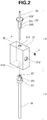
- a mixer 1 for mixing two liquids is composed of a joint member 2 and a static mixer member 3.
- the joint member 2 has a stainless steel main body 21 and a stainless steel inner tube 22 (outside diameter, 1.6 mm; inside diameter, 1.0 mm) through which a first liquid flows.
- the main body 21 has an insertion hole 211 for inserting an inner tube 22, a feed port 212 for introducing a second liquid which is orthogonal thereto and connects to the insertion hole 211 at the interior of the main body 21, and a static mixer member-connecting hole 213.
- Female threaded portions 211a, 212a and 213a corresponding to male threaded portions formed in the respective subsequently described connectors are formed on the inside walls of the insertion hole 211, the feed port 212 and the connecting hole 213 so as to enable the inner tube 22, a feed tube through which flows a second liquid, and the static mixer member 3 to be attached to the main body 21 by screw fastening.
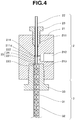
- the insertion hole 211 is composed of, from a starting end side to a far end side thereof: a female threaded portion 211a, a liquid-tight portion 211b that is formed continuous therewith and has a trapezoidal cross-sectional shape of reducing diameter which corresponds to the shape at the tip of the subsequently described connector, and an inner tube passage 211c that is formed continuous therewith.
- a female threaded portion 211a a liquid-tight portion 211b that is formed continuous therewith and has a trapezoidal cross-sectional shape of reducing diameter which corresponds to the shape at the tip of the subsequently described connector, and an inner tube passage 211c that is formed continuous therewith.
- the inner tube passage 211c of the insertion hole 211 has an inside diameter b that is shaped so as to be substantially the same as the outside diameter a of the inner tube 22 in the vicinity of a connecting portion 214 with the feed port 212, and the inner tube passage 211c from the connecting portion 214 to the connecting hole 213 has an inside diameter c that is shaped so as to be larger than the outside diameter a of the inner tube 22.
- a double tube 25 is formed by an inner side 221 of the inner tube 22 and a space 24 defined by an outer wall 222 of the inner tube 22 and an inner wall 211d of the insertion hole 211.
- the insertion hole 211 is connected at the starting end thereof to connecting hole 213.
- a hole formed of the insertion hole 211 and the connecting hole 213 thus passes entirely through the main body 21.
- the inner tube 22 has attached thereto a connector 23 having a substantially hexagonal columnar head 232 at the interior of which is formed a hole (not shown) through which passes the inner tube 22 and which is for screwing, and also, formed integrally therewith, a male threaded portion 231 and a seal 233 in the shape of an inverted truncated cone for maintaining liquid tightness at the interior of the joint main body 21.
- the inner tube 22 is inserted in this state into the insertion hole 211 having the female threaded portion 211a, and is attached to the main body 21 by screw fastening.
- the feed port 212 is composed of, from a starting end side to a far end side thereof, a female threaded portion 212a, a cross-sectionally rectangular liquid-tight portion 212b corresponding to the tip shape of the subsequently described connector, and a coupling portion 212c that extends from there to the connecting portion 214 with the insertion hole 211.
- the insertion hole 211 and the feed port 212 are connected on the far end side from the midpoint between the starting end and the far end of the insertion hole 211.
- the static mixer connecting hole 213 is composed of, from a starting end to a far end thereof, a female threaded portion 213a and a cross-sectionally rectangular liquid-tight portion 213b corresponding to the tip shape of the subsequently described connector.
- the static mixer member 3 is equipped with a cylindrical tubular body 31 (inside diameter, 3.0 mm) made of fluoroplastic or stainless steel, and an element body 32 (3 mm diameter) made of polyacetal that is inserted at the interior thereof.
- the element body 32 is inserted into the interior of the tubular body 31 in a state such that the starting end thereof becomes flush with the endface of the tubular body 31 on the double tube 25 side thereof.
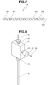
- the element body 32 has a shape in which a plurality of right-handed twist blades 321 and left-handed twist blades 322 mutually overlap in a twist axis (center axis in longitudinal direction) 323 direction.
- the top end in the diagram of the cylindrical body 31 has formed at the interior a hole (not shown) that passes through the tubular body 31.
- a fluoroplastic connector 33 having a male threaded portion 331 is attached thereto and, in this state, is inserted into the connecting hole 213 having female threaded portion 213a and secured to the main body 21 by screw fastening.
- the diameter of the insertion hole 211 is made substantially the same as the outside diameter a of the inner tube 22.
- the inside diameter c of the inner tube passage 211c from the connecting portion 214 between the insertion hole 211 and the feed port 212 to the tip 223 of the inner tube 22 on the static mixer member 3 side thereof is formed so as to be larger than the outside diameter a of the inner tube 22.
- a double tube 25 is thus formed by the inner side 221 of the inner tube 22 and the space defined by the outside wall 222 of the inner tube and the inside wall 211d of the insertion hole 211.
- the double tube 25 side endface of the tubular body 31 in the static mixer member 3 and the static mixer member 3 side endface of the double tube 25 are in touching contact.
- the static mixer member 3 side endface of the double tube 25 and the starting end (top end in FIG. 4 ) of the element body 32 are also in touching contact.
- the second liquid is introduced from the feed port 212.
- a feed tube 26 through which flows the second liquid is attached and connected by screw fastening to the feed port 212 using a connector 27 having formed therein a hole (not shown) through which passes the feed tube 26 and also having a sealing portion (not shown) for maintaining liquid tightness at the interior of the joint main body 21 and a male threaded portion 271.
- a flow reactor 4 has a construction in which a first mixer 1a for mixing two liquids and a second mixer 1b for mixing two liquids disposed at the interior of a thermostatic chamber 43 are connected in series via a PTFE tubing 42d (inside diameter, 1.5 mm).
- a pump 41a for feeding a first liquid is connected to the inner tube 22a of the first mixer 1a via a PTFE tubing 42a (inside diameter, 1.0 mm).
- a pump 41b for feeding a second liquid is connected to a feed port provided in a main body 21a of a joint member in the first mixer 1a via a PTFE tubing 42b (inside diameter, 1.0 mm) through which flows the second liquid and which is provided at the tip thereof with a connector.
- a pump 41c for feeding a third liquid is connected to a feed port in the second mixer 1b via a PTFE tubing 42c (inside diameter, 1.0 mm) through which flows the third liquid and which has a connector provided at the tip thereof, and a PTFE tubing 42e (inside diameter, 1.5 mm) is connected to the far end of the static mixer member 3b of the second mixer 1b.
- the respective liquids fed from the first liquid-feeding pump 41a and the second liquid-feeding pump 41b flow into the joint member main body 21a of the first mixer 1a for mixing two liquids and pass through the double tube constructed at the interior thereof, following which they flow into the static mixer member 3a that is in touching contact with an end of this double tube and, as the liquids are being mixed and agitated by the element body at the interior thereof, a first reaction arises.
- a first reaction mixture following the reaction passes through tubing 42d, following which it passes through an inner tube 22b in the second mixer 1b for mixing two liquids and flows into a joint member main body 21b.
- This first reaction mixture together with a third liquid that is fed from a third liquid-feeding pump 41c and flows into the interior of the joint member main body 21b, passes through a double tube at the interior of the joint member main body 21b and, as in the case of the first mixer 1a for mixing two liquids, flows into the interior of the static mixer member 3b, where a second reaction proceeds.
- the mixers for mixing two liquids and the flow reactor that are used in this invention are not limited to the above-described embodiments. Modifications and improvements may be carried out within a range where the objects and advantageous effects of the invention can be achieved.
- the inner tube 22 and the static mixer member 3 were removably screw fastened to the joint member main body 21.
- these may be removably arranged by another attaching means or, alternatively, may be connected and fastened in a non-removable state.
- discrete connectors 23 and 33 were provided for the inner tube 22 and the tubular body 31. However, instead of providing such discrete connectors, suitable attaching means may be formed in the inner tube and the tubular body themselves.
- a feed port 212 was formed in the joint member main body 21 in an embodiment that connects with the insertion hole 211 at a right angle, although an embodiment in which it connects to the insertion hole at another angle is also acceptable.
- the feed port 212 position also can be set anywhere.
- the material making up the main body 21, inner tube 22 and connector 23 was stainless steel but is not limited to this, and may instead be another metal such as titanium, iron, copper, nickel or aluminum, or may be a resin such as PTFE, FEP, PFA, PEEK or PP.
- the inside diameter of the inner tube 22 may be suitably set according to the intended purpose within a range that does not detract from the advantageous effects of the invention, although normally the inside diameter is preferably from about 0.1 mm to about 3 mm, more preferably from about 0.5 mm to about 2 mm, and even more preferably from about 0.5 mm to about 1 mm.
- the outside diameter of the inner tube 22 may be suitably set according to the intended purpose within a range that does not detract from the advantageous effects of the invention, although normally the outside diameter is preferably from about 0.8 mm to about 4 mm, more preferably from about 0.8 mm to about 3 mm, and even more preferably from about 0.8 mm to about 1.6 mm.
- the diameter c of the insertion hole 211 may be suitably set according to the intended purpose within a range that does not detract from the advantageous effects of the invention, although normally the inside diameter is preferably from about 0.1 mm to about 5 mm, more preferably from about 0.5 mm to about 4 mm, and even more preferably from about 0.8 mm to about 2 mm.
- the material making up the tubular body 31 is not limited to stainless steel, and may be another metal such as titanium, iron, copper, nickel or aluminum, or a resin such as PTFE, FEP, PFA, PEEK or PP.
- the material making up the element body 32 is not limited to polyacetal, and may be another resin such as PTFE, FEP, PFA, PEEK or PP, a metal such as stainless steel, titanium, iron, copper, nickel or aluminum, or a ceramic.
- the shape of the element body 32 may alternatively be a helical shape with a fixed direction of twist, or the element body 32 may be one in which are stacked a plurality of plates each provided with one, two or more holes.
- the material making up the connector 33 is not limited to a fluoroplastic, and may be another resin such as PEEK or PP, or a metal such as stainless steel, titanium, iron, copper, nickel or aluminum.
- the inside diameter of the tubular body 31 may be suitably set according to the intended purpose within a range that does not detract from the advantageous effects of the invention, although normally the inside diameter is preferably from about 1 mm to about 10 mm, more preferably from about 1.6 mm to about 8 mm, and even more preferably from about 2 mm to about 5 mm.
- the diameter of the element body 32 also may be suitably set according to the intended purpose within a range that does not detract from the advantageous effects of the invention, although normally this diameter is preferably from about 1 mm to about 10 mm, more preferably from about 1.6 mm to about 8 mm, and even more preferably from about 2 mm to about 5 mm.
- the flow reactor 4 is equipped with two mixers for mixing two liquids, two-stage flow synthesis is possible. However, in cases where single-stage flow synthesis is carried out, a single mixer for mixing two liquids may be used. In cases where n-stage flow synthesis is carried out, the flow reactor should be assembled in the above-described manner using n number of mixers for mixing two liquids.
- the inside diameters of tubings 42a to 42e in the flow reactor 4 may be suitably set according to the intended purpose within a range that does not detract from the advantageous effects of the invention, although normally the inside diameter is preferably from about 0.5 mm to about 10 mm, more preferably from about 0.7 mm to about 4 mm, and even more preferably from about 1 mm to about 2 mm.
- the length also may be suitably set according to the intended purpose within a range that does not detract from the advantageous effects of the invention, although normally the length is preferably from about 0.1 m to about 20 m, more preferably from about 0.2 m to about 10 m, and even more preferably from about 0.3 m to about 5 m.
- the monomer is introduced into the flow reactor in the state of a liquid. At this time, it is preferable for the monomer to be introduced from the feed port in the mixer for mixing two liquids. By being thus introduced, clogging of the flow reactor does not readily arise, pressure loss is suppressed and the polymer can be stably produced over a long period of time.
- the solvent that dissolves the monomer is not particularly limited.
- Preferred examples include ethers such as tetrahydrofuran (THF), 2-methyl THF, diethyl ether, tetrahydropyran (THP), oxepane and 1,4-dioxane; and also toluene, dichloromethane and diethoxyethane.
- the monomer concentration is not particularly limited and may be suitably set according to the intended purpose, although the concentration is preferably from 0.1 to 5 mol/L, more preferably from 0.1 to 3 mol/L, and even more preferably from 0.5 to 2 mol/L. So long as the monomer concentration is in this range, clogging of the flow reactor does not readily arise, pressure loss is suppressed, and the polymer can be stably produced over a long period of time.
- the flow rate of the monomer that flows through the flow channel in the flow reactor is not particularly limited and may be suitably set according to the intended purpose.
- the flow rate is preferably from 1 to 30 mL/min, more preferably from 5 to 20 mL/min, and even more preferably from 10 to 20 mL/min. So long as the monomer flow rate is in this range, clogging of the flow reactor does not readily arise, pressure loss is suppressed and the polymer can be stably produced over a long period of time.
- the initiator is introduced into the flow reactor in a liquid state.
- the initiator is preferably introduced from the inner tube of the mixer for mixing two liquids.
- n-butyllithium As the initiator, it is especially preferable to use n-butyllithium as the initiator.
- a polar solvent e.g., THF
- the rate of polymerization is rapid and so the reaction is generally carried out at a low temperature.
- a drawback is that, unless sec-butyllithium is used as the initiator, the initiation reaction may not proceed as desired.
- anionic polymerization is carried out in a nonpolar solvent (e.g., toluene)
- n-butyllithium which has a low reactivity, is sometimes used as the initiator.
- the inventive polymer production method using a flow reactor because reaction at close to room temperature is possible within a polar solvent, has the advantage of enabling the use of low-reactivity n-butyllithium as the initiator.
- the solvent that dissolves the initiator is not particularly limited.
- Preferred examples include ethers such as hexane, tetrahydrofuran (THF), 2-methyl THF, diethyl ether, tetrahydropyran (THP), oxepane and 1,4-dixoane; and also toluene, dichloromethane, diethoxyethane, toluene and diethyl ether.
- the initiator concentration is not particularly limited, and may be suitably set according to the type of monomer.
- the concentration is preferably from 0.01 to 0.5 mol/L, more preferably from 0.03 to 0.3 mol/L, and even more preferably from 0.05 to 0.1 mol/L.
- clogging of the flow reactor does not readily arise, pressure loss is suppressed and the polymer can be stably produced over a long period of time.
- the flow rate of the initiator flowing through the flow reactor flow channel is not particularly limited, and may be suitably set according to the intended object.
- the flow rate is preferably from 0.1 to 10 mL/min, more preferably from 0.5 to 5 mL/min, and even more preferably from 1 to 3 mL/min.
- clogging of the flow reactor does not readily arise, pressure loss is suppressed and the polymer can be stably produced over a long period of time.
- a block copolymer can be synthesized.
- a block copolymer having a maximum of n number of monomer units can be synthesized.
- the monomer type and concentration, and the flow rate of monomer passing through the flow channel in the flow reactor, are the same as described above.
- the reaction temperature (flow reactor temperature) in the production method of the invention is not particularly limited and may be suitably set according to the desired object. From the standpoint of the reaction rate, the temperature is preferably -80°C or higher, more preferably -40°C or higher, and even more preferably -20°C or higher. From the standpoint of suppressing side reactions and suppressing deactivation of the growing end of the polymer, the reaction temperature is preferably not more than 100°C, more preferably not more than 50°C, and even more preferably not more than 30°C.
- Examples of methods for terminating the reaction include the method of collecting, in a vessel containing an excess amount of a reaction terminator such as methanol, the polymerization reaction solution that has exited the flow reactor; and the method of including two or more of the above mixers for mixing two liquids in the flow reactor and having a reaction terminator such as methanol flow from one side of the final mixer for mixing two liquids.
- a reaction terminator such as methanol
- a polymer having a small dispersity Mw/Mn (a narrow molecular weight distribution) can be synthesized.
- the dispersity is preferably not more than 1.5, more preferably not more than 1.3, even more preferably not more than 1.2, and still more preferably not more than 1.15.
- Mw and Mn respectively represent the weight-average molecular weight and number-average molecular weight, these being polystyrene equivalent measured values obtained by gel permeation chromatography (GPC).
- the Mw of the polymer obtained by the production method of the invention although not particularly limited, is preferably from 1,000 to 100,000, and more preferably from 1,000 to 50,000.
- the polymer obtained by the polymer production method of the invention includes structural units of formula (1) below (in the formula, R 1 to R 6 are the same as above) and has an end that is an n-butyl group from an initiator residue, a weight-average molecular weight (Mw) of from 1,000 to 50,000, and a dispersity of 1.5 or less.
- Such a polymer can be produced by, in the above-described polymer production method, using the above-described styrene derivative as the monomer and using n-butyllithium as the initiator.
- the polymer production method of the invention is particularly suitable for producing a block copolymer that includes a first polymer block containing structural units of formula (2) below and a second polymer block containing structural units of formula (3) below wherein the structural units of formula (2) and the structural units of formula (3) are mutually differing structural units and the polymer has an end that is an n-butyl group from an initiator residue, a weight-average molecular weight (Mw) of from 1,000 to 50,000, and a dispersity of 1.5 or less.
- Mw weight-average molecular weight
- R 11 and R 21 are each independently a hydrogen atom or a methyl group
- R 12 to R 16 are each independently a hydrogen atom, an alkoxy group of 1 to 5 carbon atoms or an alkyl group of 1 to 10 carbon atoms which may be substituted with a halogen atom
- R 22 to R 26 are each independently -OSiR 27 3 or -SiR 27 3
- each R 27 is independently an alkyl group of 1 to 10 carbon atoms, a phenyl group, an alkoxy group of 1 to 5 carbon atoms or an alkylsilyl group of 1 to 5 carbon atoms
- m and n represent the number of respective structural units, each being independently an integer from 1 to 480.
- the alkyl group, alkoxy group and halogen atom are exemplified in the same way as described above.
- R 14 is preferably an alkoxy group of 1 to 5 carbon atoms, and more preferably a methoxy group.
- R 24 is preferably -SiR 27 3 , and more preferably -Si(CH 3 ) 3 .
- R 12 , R 13 , R 15 , R 16 , R 22 , R 23 , R 25 and R 26 are each preferably a hydrogen atom, an alkyl group of 1 to 10 carbon atoms, an alkoxy group of 1 to 5 carbon atoms or -SiR 7 3 ; and more preferably a hydrogen atom, a methoxy group or -Si(CH 3 ) 3 .
- the first polymer block is preferably one containing only structural units of formula (2)
- the second polymer block is preferably one containing only structural units of formula (3).
- the block copolymer is preferably one containing only the first polymer blocks and the second polymer blocks.
- the content ratio of the first polymer blocks and the second polymer blocks is preferably from 1:1 to 1:10, and more preferably from 1:1 to 1:3.
- This block copolymer can be produced by using, as the monomers in the above-described polymer production method, a monomer that gives structural units of formula (1) and a monomer that gives structural units of formula (2), using n-butyllithium as the initiator, and using a flow reactor having two or more mixers for mixing two liquids.
- FIG. 10 shows a schematic view of the flow reactor used in the Working Examples and Comparative Examples described below.
- the arrows indicate the direction of liquid flow.
- a plunger pump KP-12 or HP-12, from Flom K.K.
- PTFE tubing inside diameter, 1.0 mm; outside diameter, 1.6 mm; length, 2 m was used to connect the plunger pump and Mixer 1.
- a syringe pump 1 (Keychem-L, from YMC Co., Ltd.; Working Examples 1 to 7) or a diaphragm pump 1 (Smoothflow-Q, from Tacmina Corporation; Working Examples 8 to 10) was used for feeding liquid B, and PTFE tubing (inside diameter, 1.0 mm; outside diameter, 1.6 mm; length, 2 m) was used to connect the syringe pump 1 and Mixer 1.
- the Mixer 1 outlet and an inlet to Mixer 2 were connected by PTFE tubing 1 (inside diameter, 1.5 mm; outside diameter, 3 mm; length: 2 m (Working Examples 1-4 and 7), 5 m (Working Examples 5 and 6), 1.3 m (Comparative Example 1) or 0.7 m (Comparative Example 2)) or PFA tubing 1 (inside diameter, 2 mm; outside diameter, 3 mm; length, 1 m (Working Examples 8 to 10)).
- the other Mixer 2 inlet was connected to a syringe pump (Asia, from Syrris Ltd.) for feeding liquid C by PTFE tubing (inside diameter, 1.0 mm; outside diameter, 1.6 mm; length, 2 m).
- PTFE tubing 2 (inside diameter, 1.5 mm; outside diameter, 3 mm; length: 2 m (Working Examples 1 to 7), 1.3 m (Comparative Example 1) or 0.7 m (Comparative Example 2)) or PFA tubing 2 (inside diameter, 2 mm; outside diameter, 3 mm; length, 0.7 m (Working Examples 8 to 10)) was connected to the Mixer 2 outlet.
- Liquids A, B and C were made to flow into the reactor at respective flow rates X, Y and Z (mL/min), thereby effecting the reaction, and the effluent was analyzed by gel permeation chromatography (GPC).
- the flow channels downstream of the respective pumps and up to nine-tenths of the length of the tubing 2 were immersed in a thermostatic chamber at T°C and the temperature was regulated.
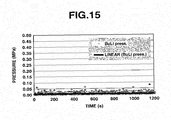
- the pressure sensor log for the fluid A pump was set to indicate the pressure trend.
- the GPC measurement conditions were as follows. Column: PLgel 3 ⁇ m MIXED-E (Agilent Technologies) Mobile phase: tetrahydrofuran (THF) Flow rate: 1.0 mL/min Column oven: 40°C Detector: UV detector Dose: polystyrene standard
- Table 1 shows collectively, for Working Examples 1 to 10 and Comparative Examples 1 and 2, the compositions of liquids A to C and their flow rates X to Z (mL/min), as well as the temperature T (°C) of the thermostatic chamber.
- the reaction was carried out under the conditions in Table 1.
- the joint member 2 used in Mixer 1 was made of stainless steel and the tubular body 31 was made of fluoroplastic.
- the static mixer element body consisted of DSP-MX3-17 polyacetal elements from Noritake Company Ltd. (17 twist blades; diameter 3 mm) that were modified by joining three such elements together to bring the number of twist blades to 51.
- Mixer 2 was made of the same materials as Mixer 1, and modified DSP-MXA3-17 elements were used as the static mixer element body here too.
- the liquid A tubing was connected to the feed port inlet on Mixer 1, and the liquid B tubing was connected to the inner tube inlet.
- the liquid C tubing was connected to the feed port inlet on Mixer 2, and Tubing 1 was connected to the inner tube inlet.
- FIG. 11 shows the pressure trend during the reaction. There were substantially no pressure fluctuations over 10 minutes.
- FIG. 12 shows the pressure trend during the reaction. There were substantially no pressure fluctuations over 20 minutes.
- FIG. 13 shows the pressure trend during the reaction. There were substantially no pressure fluctuations over 15 minutes.
- FIG. 14 shows the pressure trend during the reaction. There were substantially no pressure fluctuations over 10 minutes.
- FIG. 15 shows the pressure trend during the reaction. There were substantially no pressure fluctuations over 20 minutes.
- the solvent was driven off with an evaporator from 308 g of the effluent, bringing the volume down to 125 g, after which 501 g of methanol was added dropwise at room temperature.
- the resulting white suspension was filtered with filter paper (No. 5B from Kiriyama Glass Co.) and then washed with 153 g of methanol.
- the resulting white solid was vacuum dried (50°C, 2.5 hours), giving 16 g of polymethoxystyrene-b-polytrimethylsilylstyrene block copolymer.
- FIG. 16 shows the 1 H-NMR chart of the resulting polymer.
- FIG. 17 shows the pressure trend during the reaction. There were substantially no pressure fluctuations over 15 minutes.
- the reaction was carried out under the conditions in Table 1.
- a T-mixer (from Sanko Seiki Kogyo KK; made of stainless steel; inside diameter, 0.25 mm) was used as Mixer 1.
- the respective pumps were connected so that liquid A and liquid B meet at 180°C.
- a T-mixer (from Sanko Seiki Kogyo KK; made of stainless steel; inside diameter, 1.0 mm) was used as Mixer 2.
- the respective pumps were connected so that the liquid that emerges from Mixer 1 and liquid C meet at 180°C.
- FIG. 18 shows the pressure trend during the reaction. Sudden pressure fluctuations are apparent starting about 5 minutes after liquid feeding.
- FIG. 19 shows the pressure trend after 35 minutes of liquid feeding. Some pressure fluctuation and a rise in pressure over time are apparent.
Landscapes
- Chemical & Material Sciences (AREA)
- Chemical Kinetics & Catalysis (AREA)
- Health & Medical Sciences (AREA)
- Organic Chemistry (AREA)
- Medicinal Chemistry (AREA)
- Polymers & Plastics (AREA)
- Engineering & Computer Science (AREA)
- Materials Engineering (AREA)
- Inorganic Chemistry (AREA)
- Emergency Medicine (AREA)
- Dispersion Chemistry (AREA)
- Polymerisation Methods In General (AREA)
- Polymerization Catalysts (AREA)
- Graft Or Block Polymers (AREA)
- Addition Polymer Or Copolymer, Post-Treatments, Or Chemical Modifications (AREA)
Applications Claiming Priority (3)
| Application Number | Priority Date | Filing Date | Title |
|---|---|---|---|
| JP2016019733 | 2016-02-04 | ||
| PCT/JP2017/003912 WO2017135398A1 (ja) | 2016-02-04 | 2017-02-03 | ポリマーの製造方法 |
| EP17747549.8A EP3412690A4 (de) | 2016-02-04 | 2017-02-03 | Polymerherstellungsverfahren |
Related Parent Applications (1)
| Application Number | Title | Priority Date | Filing Date |
|---|---|---|---|
| EP17747549.8A Division EP3412690A4 (de) | 2016-02-04 | 2017-02-03 | Polymerherstellungsverfahren |
Publications (2)
| Publication Number | Publication Date |
|---|---|
| EP3670543A2 true EP3670543A2 (de) | 2020-06-24 |
| EP3670543A3 EP3670543A3 (de) | 2020-07-22 |
Family
ID=59500726
Family Applications (2)
| Application Number | Title | Priority Date | Filing Date |
|---|---|---|---|
| EP20156492.9A Withdrawn EP3670543A3 (de) | 2016-02-04 | 2017-02-03 | Polymerherstellungsverfahren |
| EP17747549.8A Withdrawn EP3412690A4 (de) | 2016-02-04 | 2017-02-03 | Polymerherstellungsverfahren |
Family Applications After (1)
| Application Number | Title | Priority Date | Filing Date |
|---|---|---|---|
| EP17747549.8A Withdrawn EP3412690A4 (de) | 2016-02-04 | 2017-02-03 | Polymerherstellungsverfahren |
Country Status (7)
| Country | Link |
|---|---|
| US (2) | US11059912B2 (de) |
| EP (2) | EP3670543A3 (de) |
| JP (1) | JP6922745B2 (de) |
| KR (1) | KR102801416B1 (de) |
| CN (2) | CN108884177B (de) |
| TW (1) | TWI726051B (de) |
| WO (1) | WO2017135398A1 (de) |
Families Citing this family (10)
| Publication number | Priority date | Publication date | Assignee | Title |
|---|---|---|---|---|
| WO2018225685A1 (ja) * | 2017-06-06 | 2018-12-13 | 日産化学株式会社 | ブロックポリマーの製造方法 |
| WO2019031435A1 (ja) * | 2017-08-08 | 2019-02-14 | 日産化学株式会社 | ブロックポリマーの製造方法 |
| CN107722199B (zh) * | 2017-08-24 | 2019-09-06 | 中国科学院长春应用化学研究所 | 一种基于管式反应装置连续制备嵌段/星形聚合物的方法 |
| EP3689915B1 (de) * | 2017-09-28 | 2023-12-06 | FUJIFILM Corporation | Verfahren zur herstellung eines polymers und fliessreaktionssystem zur herstellung eines polymers |
| JP6956256B2 (ja) * | 2018-03-29 | 2021-11-02 | 富士フイルム株式会社 | 重合体の製造方法、及び重合体を製造するフロー式反応システム |
| CN109260977B (zh) * | 2018-10-26 | 2023-09-29 | 中北大学 | 一种可切换自由/受限式撞击流混合器及其使用方法 |
| JP7413795B2 (ja) * | 2020-01-27 | 2024-01-16 | 住友ゴム工業株式会社 | 共重合体、ゴム組成物及びタイヤ |
| JP7831288B2 (ja) | 2020-06-12 | 2026-03-17 | 日産化学株式会社 | ブロックコポリマーを含む生体物質への適合性を有するコーティング膜 |
| US20230392037A1 (en) | 2020-10-23 | 2023-12-07 | Nissan Chemical Corporation | Biological substance low adhesion material comprising copolymer |
| JP2023165103A (ja) * | 2022-05-02 | 2023-11-15 | 国立大学法人京都大学 | シークエンスオリゴマー及びポリマー並びにその製造方法 |
Citations (1)
| Publication number | Priority date | Publication date | Assignee | Title |
|---|---|---|---|---|
| JP2009067999A (ja) | 2007-08-21 | 2009-04-02 | Kyoto Univ | Mw/Mnが1.25以下であるポリマーの製造方法 |
Family Cites Families (20)
| Publication number | Priority date | Publication date | Assignee | Title |
|---|---|---|---|---|
| US4965327A (en) * | 1989-10-23 | 1990-10-23 | The Goodyear Tire & Rubber Company | Synthesis of polydiene rubber by high solids solution polymerization |
| JPH0632851A (ja) * | 1992-07-20 | 1994-02-08 | Shin Etsu Chem Co Ltd | tert−ブトキシカルボニル基で部分エステル化されたp−ヒドロキシαメチルスチレン−スチレンブロック共重合体及びその製造方法 |
| JPH0656910A (ja) * | 1992-08-05 | 1994-03-01 | Toagosei Chem Ind Co Ltd | アニオン重合による重合体の連続式製造方法 |
| JP2001029764A (ja) * | 1999-07-19 | 2001-02-06 | Noritake Co Ltd | インライン型流体攪拌装置 |
| US6448353B1 (en) * | 2000-02-08 | 2002-09-10 | 3M Innovative Properties Company | Continuous process for the production of controlled architecture materials |
| JP2004149549A (ja) | 2000-07-03 | 2004-05-27 | Teijin Ltd | 水素化スチレン系ブロック共重合体の連続製造方法 |
| US20040156763A1 (en) * | 2001-03-12 | 2004-08-12 | Wood Mark D. | Reactor apparatus and mixing inlet and methods |
| DE602005011303D1 (de) * | 2004-08-13 | 2009-01-08 | Kuraray Co | Verfahren zur kontinuierlichen herstellung von (meth)acrylsäureesterpolymer oder copolymer |
| JP5457027B2 (ja) * | 2006-05-16 | 2014-04-02 | 日本曹達株式会社 | ブロックコポリマー |
| US20080058482A1 (en) * | 2006-08-29 | 2008-03-06 | 3M Innovative Properties Company | Continuous process polymerization of (meth)acrylate copolymers |
| CN101616940B (zh) | 2006-09-20 | 2012-06-20 | 东丽株式会社 | 热塑性共聚物的制造方法 |
| JP2008101203A (ja) | 2006-09-20 | 2008-05-01 | Toray Ind Inc | カルボキシル基含有アクリル共重合体の製造方法 |
| WO2011016226A1 (ja) | 2009-08-04 | 2011-02-10 | 日本曹達株式会社 | 高分子量共重合体 |
| JP5454027B2 (ja) * | 2009-09-09 | 2014-03-26 | 日産自動車株式会社 | 充電制御装置及び充電制御方法 |
| JPWO2011086926A1 (ja) | 2010-01-18 | 2013-05-16 | 日本曹達株式会社 | スチレン系重合体及びその製造方法 |
| WO2015041146A1 (ja) * | 2013-09-20 | 2015-03-26 | Dic株式会社 | ブロック共重合体の製造方法及びその方法により得られたブロック共重合体 |
| WO2015046392A1 (ja) * | 2013-09-30 | 2015-04-02 | 日本ゼオン株式会社 | 共役ジエン系ゴムの製造方法 |
| CN105612226B (zh) * | 2013-11-14 | 2018-11-23 | Dic株式会社 | 水性颜料分散体和喷墨记录用水性油墨 |
| JP2015120642A (ja) * | 2013-12-20 | 2015-07-02 | 株式会社堀場エステック | 連続反応装置及びこれを用いる連続合成方法 |
| JP6461667B2 (ja) * | 2015-03-25 | 2019-01-30 | 富士フイルム株式会社 | 重合体の製造方法 |
-
2017
- 2017-02-03 WO PCT/JP2017/003912 patent/WO2017135398A1/ja not_active Ceased
- 2017-02-03 US US16/075,283 patent/US11059912B2/en active Active
- 2017-02-03 KR KR1020187025458A patent/KR102801416B1/ko active Active
- 2017-02-03 CN CN201780009719.3A patent/CN108884177B/zh active Active
- 2017-02-03 CN CN202011260625.3A patent/CN112375167A/zh active Pending
- 2017-02-03 JP JP2017565640A patent/JP6922745B2/ja active Active
- 2017-02-03 EP EP20156492.9A patent/EP3670543A3/de not_active Withdrawn
- 2017-02-03 EP EP17747549.8A patent/EP3412690A4/de not_active Withdrawn
- 2017-02-03 TW TW106103726A patent/TWI726051B/zh active
-
2021
- 2021-06-04 US US17/339,605 patent/US20210340287A1/en not_active Abandoned
Patent Citations (1)
| Publication number | Priority date | Publication date | Assignee | Title |
|---|---|---|---|---|
| JP2009067999A (ja) | 2007-08-21 | 2009-04-02 | Kyoto Univ | Mw/Mnが1.25以下であるポリマーの製造方法 |
Also Published As
| Publication number | Publication date |
|---|---|
| JP6922745B2 (ja) | 2021-08-18 |
| CN112375167A (zh) | 2021-02-19 |
| KR20180107226A (ko) | 2018-10-01 |
| US20190062464A1 (en) | 2019-02-28 |
| WO2017135398A1 (ja) | 2017-08-10 |
| CN108884177B (zh) | 2021-04-06 |
| US11059912B2 (en) | 2021-07-13 |
| CN108884177A (zh) | 2018-11-23 |
| EP3670543A3 (de) | 2020-07-22 |
| JPWO2017135398A1 (ja) | 2018-11-29 |
| TW201741342A (zh) | 2017-12-01 |
| EP3412690A1 (de) | 2018-12-12 |
| US20210340287A1 (en) | 2021-11-04 |
| EP3412690A4 (de) | 2019-05-15 |
| KR102801416B1 (ko) | 2025-04-29 |
| TWI726051B (zh) | 2021-05-01 |
Similar Documents
| Publication | Publication Date | Title |
|---|---|---|
| US20210340287A1 (en) | Polymer production method | |
| JP6559322B2 (ja) | 陰イオン重合開始剤の製造方法、製造装置及びこれから製造される陰イオン重合開始剤 | |
| EP3031838A1 (de) | Verfahren zur herstellung von blockcopolymer und so hergestelltes blockcopolymer | |
| WO2015093611A1 (ja) | 連続反応装置及びこれを用いる連続重合方法 | |
| Li et al. | A surfactant-free emulsion RAFT polymerization of methyl methacrylate in a continuous tubular reactor | |
| CN105143276A (zh) | 制备基于c3-c8单烯属不饱和单-或二羧酸或其酸酐和盐的高度支化聚合物的连续方法 | |
| JP6498790B2 (ja) | アニオン重合開始剤の製造方法、製造装置およびこれから製造されるアニオン重合開始剤 | |
| CN110922330A (zh) | 一种丙烯酸羟乙酯的制备方法 | |
| CN117362556A (zh) | 嵌段聚合物的制造方法 | |
| JP7679567B2 (ja) | ポリマーの製造方法 | |
| CN102558407A (zh) | 一种氯化聚氯乙烯及其制备方法和应用 | |
| JP2019043883A (ja) | アルキルリチウム、化合物の製造方法、ポリマー、及びポリマーの製造方法 | |
| JP2020143277A (ja) | ポリマーの製造方法 | |
| CN113105380A (zh) | 一种以乙酸为原料通过微反应器制备过氧乙酸的新工艺 | |
| JP3730615B2 (ja) | カルボン酸系重合体の製造法 | |
| JP2025176981A (ja) | ポリマーの製造方法 | |
| JP4417811B2 (ja) | カチオン重合による重合体の製造方法 | |
| CN104529689B (zh) | 9,9,10,10-四苯基-9,10-去氧蒽醌的制备方法 | |
| EP4041712A1 (de) | Verfahren der kontinuierlichen flusssynthese zur herstellung von isoniazid | |
| KR20180012431A (ko) | 음이온 중합개시제의 제조장치 및 이를 이용한 음이온 중합개시제의 제조방법 | |
| JP2014172924A (ja) | 重合体微粒子の製造方法、及び分散体 | |
| JP2021181519A (ja) | ランダムコポリマー、及びその製造方法 | |
| CN1307204C (zh) | 羧酸系聚合物的制备方法 | |
| TWI791532B (zh) | 嵌段聚合物的製造方法 | |
| JP2012144674A (ja) | ラジカル重合体の製造方法 |
Legal Events
| Date | Code | Title | Description |
|---|---|---|---|
| PUAI | Public reference made under article 153(3) epc to a published international application that has entered the european phase |
Free format text: ORIGINAL CODE: 0009012 |
|
| STAA | Information on the status of an ep patent application or granted ep patent |
Free format text: STATUS: THE APPLICATION HAS BEEN PUBLISHED |
|
| PUAL | Search report despatched |
Free format text: ORIGINAL CODE: 0009013 |
|
| AC | Divisional application: reference to earlier application |
Ref document number: 3412690 Country of ref document: EP Kind code of ref document: P |
|
| AK | Designated contracting states |
Kind code of ref document: A2 Designated state(s): AL AT BE BG CH CY CZ DE DK EE ES FI FR GB GR HR HU IE IS IT LI LT LU LV MC MK MT NL NO PL PT RO RS SE SI SK SM TR |
|
| AK | Designated contracting states |
Kind code of ref document: A3 Designated state(s): AL AT BE BG CH CY CZ DE DK EE ES FI FR GB GR HR HU IE IS IT LI LT LU LV MC MK MT NL NO PL PT RO RS SE SI SK SM TR |
|
| RIC1 | Information provided on ipc code assigned before grant |
Ipc: C08F 4/48 20060101ALI20200618BHEP Ipc: C08F 297/02 20060101ALI20200618BHEP Ipc: C08F 12/04 20060101ALI20200618BHEP Ipc: C08F 2/01 20060101AFI20200618BHEP |
|
| STAA | Information on the status of an ep patent application or granted ep patent |
Free format text: STATUS: THE APPLICATION IS DEEMED TO BE WITHDRAWN |
|
| 18D | Application deemed to be withdrawn |
Effective date: 20210123 |