EP3667180A1 - Gargerät mit einem garraum und einer luftleiteinheit - Google Patents
Gargerät mit einem garraum und einer luftleiteinheit Download PDFInfo
- Publication number
- EP3667180A1 EP3667180A1 EP19208599.1A EP19208599A EP3667180A1 EP 3667180 A1 EP3667180 A1 EP 3667180A1 EP 19208599 A EP19208599 A EP 19208599A EP 3667180 A1 EP3667180 A1 EP 3667180A1
- Authority
- EP
- European Patent Office
- Prior art keywords
- air
- cooking
- opening
- cooking space
- web segments
- Prior art date
- Legal status (The legal status is an assumption and is not a legal conclusion. Google has not performed a legal analysis and makes no representation as to the accuracy of the status listed.)
- Granted
Links
Images


Classifications
-
- F—MECHANICAL ENGINEERING; LIGHTING; HEATING; WEAPONS; BLASTING
- F24—HEATING; RANGES; VENTILATING
- F24C—DOMESTIC STOVES OR RANGES ; DETAILS OF DOMESTIC STOVES OR RANGES, OF GENERAL APPLICATION
- F24C15/00—Details
- F24C15/32—Arrangements of ducts for hot gases, e.g. in or around baking ovens
- F24C15/322—Arrangements of ducts for hot gases, e.g. in or around baking ovens with forced circulation
-
- H—ELECTRICITY
- H05—ELECTRIC TECHNIQUES NOT OTHERWISE PROVIDED FOR
- H05B—ELECTRIC HEATING; ELECTRIC LIGHT SOURCES NOT OTHERWISE PROVIDED FOR; CIRCUIT ARRANGEMENTS FOR ELECTRIC LIGHT SOURCES, IN GENERAL
- H05B6/00—Heating by electric, magnetic or electromagnetic fields
- H05B6/64—Heating using microwaves
- H05B6/647—Aspects related to microwave heating combined with other heating techniques
- H05B6/6473—Aspects related to microwave heating combined with other heating techniques combined with convection heating
Definitions
- the invention relates to a cooking device with a cooking space delimited by cooking space walls, a door for closing the cooking space, an air guide unit in a ventilation communication with the cooking space, an air opening in a cooking space wall for connecting the cooking space to the air control unit, one outside the cooking space and inside the air control unit arranged blower for generating an air flow, wherein the air opening is provided with a grid which consists of individual webs in order to form holes or opening segments between the webs.
- a cooking chamber wall is provided in the rear part of the cooking chamber, which separates a blower room located behind it from the cooking chamber.
- a blower with an annular heating element is accommodated in the blower compartment.
- the cooking space wall between the blower compartment and the cooking space generally has an opening which allows the air flow generated by the blower to pass through the cooking space wall. This opening can, as in the publication DE 23 39 446 A1 shown, be closed by an attached grid against an intervention.
- Such a cooking device is a hot air oven, among other things, from the publication DE 10 2007 061 286 A1 known.
- the fan is arranged behind the central, largest passage opening and is intended to draw in the air flow from the cooking space through the passage openings in the cooking space wall.
- the webs In the case of round holes, the webs have different widths, which reduce the passage cross section of the opening. Stability can suffer with straight webs so that they can be bent easily, for example when touched. Another characteristic of fan operation is that when using straight webs, vibrations occur that are in the resonance range at normal fan speeds.
- the invention is therefore based on the object of improving a cooking appliance with an air guiding unit with regard to the effect and the noise.
- the advantages achievable with the invention consist in the fact that an enlarged total cross-section for the air opening is created without increasing the overall diameter of the air opening. Furthermore, the stability of the cooking space wall in the area of the air opening is increased, so that damage or vibrations in the area are avoided.
- the webs of the grid have a structure made of straight web segments, which forms a plurality of polygonal holes, wherein a polygonal hole is surrounded by a plurality of the web segments.
- the stability of the cooking space wall in the area of the air opening is also improved in that all web segments have the same width. In this way, a uniform heat flow and a uniform temperature distribution in the web segments can be achieved, whereby stresses in the webs of the grid are reduced. This is particularly relevant at high process temperatures in the cooking space, for example during pyrolytic cleaning.
- the web segments are formed in one piece with the cooking chamber wall containing the air opening.
- the holes are preferably produced by machining the material of the cooking space wall with a cutting tool.
- the stability of the cooking space wall is improved by the one-piece design, in particular by reduced tensions under thermal load.
- the structure of the web segments is designed such that the web segments meet at an angle not equal to 90 degrees and not equal to 180 degrees.
- Each web segment thus meets two adjacent web segments and forms a star-shaped connection. This means that deformations or twists due to the thermal expansion of a single web are always dissipated in a star shape on two adjacent webs, so that stresses do not even arise within one web.
- the web segments are structured in such a way that the holes are five, hexagonal or octagonal in shape. This results in a stable overall structure of the lattice and an optically positive appearance.
- the structure of the web segments is designed in such a way that there is a zigzag course in the radial extension from the center to the opening edge of the air opening and that there is also a zigzag course in the circumferential direction. This allows the webs expand or shrink more easily without creating tension at the connection points or within the webs themselves.
- the zigzag arrangement provides a so-called accordion effect for the longitudinal course of the webs.
- the structure of the web segments is set up to form the polygonal holes with a width across flats in the range from 3 mm to 12 mm, the web width of the web segments having a value in the range from 0.5 mm to 3 mm. This means that the bar segments are thin enough not to brake or redirect air conveyed through the opening too strongly, on the other hand there is good stability of the entire grille.
- the air opening is circular and has a diameter in the range from 5 cm to 25 cm.
- a fan whose fan wheel corresponds approximately to the diameter mentioned can be used and can be arranged flat behind the cooking chamber wall.
- An oven with a circulating air function a steam cooker, a hot air oven or a microwave oven, preferably with a circulating air and / or hot air function, can be used as the cooking device.
- a cooking space wall preferably the rear wall, is provided with an air opening or steam opening.
- the Fig. 1 shows, using the example of an oven 1 with a fan function or hot air function, the cooking space 2, which comprises an air guide unit 3 with a fan 31 behind its rear wall 21.
- the rear wall 21 comprises an air opening 4 in order to provide the connection of the air guiding unit 3 or the blower 31 to the cooking space 2.
- the air opening 4 is covered with a grille 41 so that no objects can get into the blower 31 or air guiding unit 3 behind it and that the user does not reach into it can.
- the oven 1 further comprises a heating device 5 in order to heat the cooking space.
- the operating and display device 81 is used for user input and operating actions and for displaying conditions such as the temperature of the cooking space 2 or the food to be cooked.
- a control device 82 is connected to the operating and display device 81 and serves to activate and deactivate the fan 31 and the heating device 5 in order to control the cooking process specified by the user.
- the air is sucked out of the cooking space 2 through the air opening 4 and blown into the cooking space 2 by means of the air guide unit 3 to the outlet openings 42.
- the air in the air duct 3 is additionally heated by means of an additional air heater.
- the cooking space 2 comprises a loading opening on the front, which can be closed by means of the door 11.
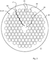
- Fig. 2 shows the air opening 4 with the grid 41 attached to it.
- This comprises a honeycomb structure, so that the webs 42 are formed from web segments 43, each of which lies at an obtuse angle to the web segments 43 that respectively meet.
- the web segments 43 are each at an angle of approximately or exactly 120 degrees to one another.
- Each web 42 which extends from the middle part 45 to the outer edge 46 or extends from one side to the other, runs in a zigzag shape Z, no web 42 runs in a straight line.
- Fig. 3 shows a section of the honeycomb structure 41.
- the individual web segment 43 which delimits a hexagonal hole 44, can be seen.
- Six such webs 43 each surround a hole 44.
- the web width B is essentially constant over the entire length of the web segment 43. The dimensioning is chosen such that the smallest possible partial air deflections or turbulences in the air flow are caused in order to optimize the flow against the fan wheel 32 of the blower unit 31. Furthermore, this constant web width B creates an enlarged air opening compared to a grille with round holes.
- the holes 44 are preferably formed with a width across flats in the range from 3 mm to 15 mm, the width across flats defining the distance between a straight side of the hole 44 and the opposite straight side. Values in the range from 0.5 mm to 3 mm have proven to be advantageous as web width B, preferably 1 mm to 2 mm.
Landscapes
- Engineering & Computer Science (AREA)
- Chemical & Material Sciences (AREA)
- Combustion & Propulsion (AREA)
- Mechanical Engineering (AREA)
- General Engineering & Computer Science (AREA)
- Physics & Mathematics (AREA)
- Electromagnetism (AREA)
- Baking, Grill, Roasting (AREA)
Abstract
Description
- Die Erfindung betrifft ein Gargerät mit einem Garraum durch Garraumwände begrenzt, einer Tür zum Verschließen des Garraumes, einer Luftleiteinheit in lüftungstechnisch kommunizierender Verbindung mit dem Garraum, einer Luftöffnung in einer Garraumwand zur Verbindung des Garraumes mit der Luftleiteinheit, einem außerhalb des Garraumes und innerhalb der Luftleiteinheit angeordnetem Gebläse zum Erzeugen eines Luftstromes, wobei die Luftöffnung mit einem Gitter versehen ist, das aus einzelnen Stegen besteht, um zwischen den Stegen Löcher oder Öffnungssegmente auszubilden.
- Bei einem als Backofen ausgebildeten Gargerät ist im hinteren Teil des Garraumes eine Garraumwand vorgesehen, die einen dahinterliegenden Gebläseraum vom Garraum trennt. In dem Gebläseraum ist ein Gebläse mit ringförmigem Heizkörper aufgenommen. Die Garraumwand zwischen Gebläseraum und Garraum weist in der Regel eine Öffnung auf, welche den Durchtritt des vom Gebläse erzeugten Luftstroms durch die Garraumwand ermöglicht. Diese Öffnung kann, wie in der Druckschrift
DE 23 39 446 A1 gezeigt, durch ein aufgesetztes Gitter gegen einen Eingriff verschlossen sein. - Eine andere Möglichkeit einen Eingriff in die Öffnung zu verhindern zeigt die Druckschrift
DE 44 13 252 A1 durch den Einsatz eines Luftkanalkörpers mit zahlreichen Röhren, welche einen runden oder quadratischen Querschnitt aufweisen. Eine weitere Möglichkeit ist es, eine Vielzahl von kreisrunden Löchern als Durchlassöffnungen in die Garraumzwischenwand einzubringen, wie es in der DruckschriftDE 30 69 018 D1 gezeigt ist. - Ein solches Gargerät ist als Heißluftbackofen unter anderem aus der Druckschrift
DE 10 2007 061 286 A1 bekannt. Hinter der zentralen, größten Durchlassöffnung ist das Gebläse angeordnet, welches vorgesehen ist, den Luftstrom aus dem Garraum durch die Durchlassöffnungen in der Garraumwand anzusaugen. - Bei runden Löchern weisen die Stege dabei unterschiedliche Breiten auf, welche den Durchlassquerschnitt der Öffnung reduzieren. Bei gerade verlaufenden Stegen kann die Stabilität leiden, sodass sich diese leicht verbiegen lassen, beispielsweise bei Berührung. Eine weitere Eigenschaft beim Lüfterbetrieb ist, dass beim Einsatz von durchgehend geraden Stegen Vibrationen auftreten, die bei üblichen Lüfterdrehzahlen im Resonanzbereich liegen.
- Der Erfindung liegt somit die Aufgabe zu Grunde, ein Gargerät mit einer Luftleiteinheit hinsichtlich der Wirkung und der Geräuschentwicklung zu verbessern.
- Erfindungsgemäß wird unter anderem diese Aufgabe durch ein Gargerät mit den Merkmalen des unabhängigen Anspruchs 1 gelöst. Vorteilhafte Ausgestaltungen und Weiterbildungen der Erfindung ergeben sich aus den jeweils abhängigen Ansprüchen.
- Die mit der Erfindung erreichbaren Vorteile bestehen darin, dass ein vergrößerter Summenquerschnitt für Luftöffnung geschaffen wird, ohne den Gesamtdurchmesser der Luftöffnung zu vergrößern. Ferner wird die Stabilität der Garraumwand im Bereich der Luftöffnung erhöht, sodass Beschädigungen oder Vibrationen in dem Bereich vermieden werden. Hierzu weisen die Stege des Gitters eine Struktur aus geraden Stegsegmenten auf, die eine Mehrzahl von mehreckigen Löchern ausbildet wobei jeweils ein mehreckiges Loch von einer Mehrzahl von den Stegsegmenten umgeben ist.
- Gemäß einer bevorzugten Ausführung der Erfindung wird die Stabilität der Garraumwand im Bereich der Luftöffnung auch dadurch verbessert, dass alle Stegsegmente die gleiche Breite aufweisen. Hierdurch kann ein gleichmäßiger Wärmefluss und eine gleichmäßige Temperaturverteilung in den Stegsegmenten erreicht werden, wodurch Spannungen in den Stegen des Gitters reduziert werden. Dies ist insbesondere bei hohen Prozesstemperaturen im Garraum, beispielsweise bei einer pyrolytischen Reinigung, relevant.
- In einer weiteren, insgesamt zweckmäßigen Ausführung sind die Stegsegmente einteilig mit der, die Luftöffnung enthaltende Garraumwand ausgebildet. Vorzugsweise sind die Löcher erzeugt, durch eine Bearbeitung des Materials der Garraumwand mit einem Schneidewerkzeug. Durch die einteilige Ausführung wird die Stabilität der Garraumwand verbessert, insbesondere durch reduzierte Spannungen bei thermischer Belastung.
- Gemäß einer bevorzugten Ausführung der Erfindung ist die Struktur der Stegsegmente so ausgebildet, dass die Stegsegmente jeweils in einem Winkel ungleich 90 Grad und ungleich 180 Grad aufeinandertreffen. Somit trifft jedes Stegsegment auf zwei benachbarte Stegsegmente und bildet eine sternförmige Verbindung. Das bedeutet, dass Verformungen oder Verwindungen aufgrund Wärmeausdehnung eines einzelnen Stegs immer auf zwei benachbarte Stege sternförmig abgeleitet werden, sodass Spannungen innerhalb eines Steges erst gar nicht entstehen.
- In einer weiteren, insgesamt zweckmäßigen Ausführung sind die Stegsegmente so strukturiert, dass die Löcher fünf, sechseckig oder achteckig geformt sind. Dies ergibt eine stabile Gesamtstruktur des Gitters und eine optisch positive Anmutung.
- Die Struktur der Stegsegmente ist dabei so ausgebildet, dass sich in radialer Erstreckung von der Mitte zum Öffnungsrand der Luftöffnung ein Zickzack-Verlauf ergibt und dass sich in Umfangsrichtung ebenfalls ein Zickzack-Verlauf ergibt. Dadurch können sich die Stege leichter ausdehnen oder schrumpfen, ohne dass es Spannungen an den Anbindungsstellen oder innerhalb der Stege selbst entstehen. Die Zickzack-Anordnung stellt einen sogenannten Ziehharmonika-Effekt für den Längsverlauf der Stege bereit.
- in einer insgesamt vorteilhaften Ausführung Struktur der Stegsegmente dazu eingerichtet, die mehreckigen Löcher mit einer Schlüsselweite im Bereich von 3 mm bis 12 mm auszubilden, wobei die Stegbreite der Stegsegmente einen Wert im Bereich 0,5 mm bis 3 mm aufweist. Damit sind die Stegsegmente dünn genug, um durch die Öffnung geförderte Luft nicht zu stark zu bremsen oder umzulenken, andererseits ist eine gute Stabilität des gesamten Gitters gegeben.
- In einer insgesamt zweckmäßigen Ausführung ist die Luftöffnung ist kreisförmig und einen Durchmesser im Bereich von 5 cm bis 25 cm aufweist. Damit kann ein Ventilator, dessen Lüfterrad etwa dem genannten Durchmesser entspricht verwendet werden und flachbauend hinter der Garraumwand angeordnet werden. Bei den genannten Durchmessern ist es dabei vorteilhaft, die Struktur der Stegsegmente so auszubilden, dass radial 3 bis 8 Löcher von der Mitte der Luftöffnung bis zum Außenrand der Öffnung angeordnet sind, bevorzugt 4 bis 5 Löcher.
- Als Gargerät kommt ein Backofen mit Umluftfunktion, ein Dampfgarer, ein Heißluftbackofen oder ein Mikrowellenofen, bevorzugt mit Umluft- und/oder Heißluftfunktion in Frage. Insgesamt ist für das Gargerät von Bedeutung, dass eine Garraumwand, bevorzugt die Rückwand, mit einer Luftöffnung oder Dampföffnung versehen ist.
- In einer zweckmäßigen Weiterbildung ist
Ein Ausführungsbeispiel der Erfindung ist in den Zeichnungen rein schematisch dargestellt und wird nachfolgend näher beschrieben. Es zeigen: - Fig. 1:
- ein Gargerät mit Blick in den Garraum;
- Fig. 2:
- eine Detailansicht der Luftöffnung in der Garraumwand und
- Fig. 3:
- eine vergrößerte Ansicht der Struktur der Stegsegmente und die Löcher.
- Die
Fig.1 zeigt am Beispiel eines Backofens 1 mit Lüfterfunktion bzw. Heißluftfunktion den Garraum 2, der hinter seiner Rückwand 21 eine Luftleiteinheit 3 mit einem Gebläse 31 umfasst. Die Rückwand 21 umfasst dabei eine Luftöffnung 4, um die Verbindung der Luftleiteinheit 3 oder des Gebläses 31 mit dem Garraum 2 bereitzustellen. Die Luftöffnung 4 ist mit einem Gitter 41 abgedeckt, damit keine Gegenstände in das dahinterliegende Gebläse 31 oder Luftleiteinheit 3 gelangen können und dass der Benutzer dort nicht hineingreifen kann. Der Backofen 1 umfasst ferner eine Heizeirichtung 5, um den Garraum zu erhitzen. Die Bedien- und Anzeigeeinrichtung 81 dient zu Benutzereingaben und Bedienhandlungen und zum Anzeigen von Zuständen, wie Temperatur des Garraums 2 oder des Gargutes. Eine Steuereinrichtung 82 steht mit der Bedien- und Anzeigeeinrichtung 81 in Verbindung und dient dazu, das Gebläse 31 und die Heizeinrichtung 5 zu aktivieren und zu deaktivieren, um den vom Benutzer vorgegeben Garprozess zu steuern. Im gezeigten Beispiel wird durch die Luftöffnung 4 die Luft aus dem Garraum 2 angesaugt und mittels der Luftleiteinheit 3 zu den Auslassöffnungen 42 in den Garraum 2 hineingeblasen. Bei einem Heißluftbackofen wird die Luft in der Luftleiteitheit 3 zusätzlich erhitzt mittels eines zusätzlichen Luftheizers. Zu erkennen ist ferner, dass der Garraum 2 frontseitig eine Beladungsöffnung umfasst, die mittels der Tür 11 verschlossen werden kann. -
Fig. 2 zeigt die Luftöffnung 4 mit dem darauf angebrachten Gitter 41. Dieses umfasst eine Wabenstruktur, sodass die Stege 42 aus Stegsegmenten 43 gebildet sind, die jeweils im stumpfen Winkel zu den jeweils auftreffenden Stegsegmenten 43 liegen. Bei sechseckigen Löchern 44 liegen die Stegsegmente 43 jeweils in einem Winkel von etwa oder genau 120 Grad zueinander. Jeder Steg 42, der vom Mittelteil 45 zum äußeren Rand 46 verläuft oder der sich von einer Seite zur anderen erstreckt, verläuft dabei zickzackförmig Z, kein Steg 42 verläuft geradlinig. -
Fig. 3 zeigt einen Ausschnitt des wabenförmig strukturierten Gitters 41. Zu erkennen ist das einzelne Stegsegment 43, das ein sechseckförmiges Loch 44 begrenzt. Sechs solcher Stege 43 umgeben dabei jeweils ein Loch 44. Die Stegbreite B ist dabei über gesamte Länge des Stegsegments 43 im Wesentlichen konstant. Die Dimensionierung ist so gewählt, dass möglichst kleine partielle Luftumlenkungen oder Verwirbelungen des Luftstromes verursacht werden, um das Anströmen des Lüfterrades 32 der Gebläseeinheit 31 zu optimieren. Ferner wird durch diese konstante Stegbreite B eine vergrößerte Luftöffnung geschaffen, gegenüber einem Gitter mit runden Löchern. Bevorzugt sind die Löcher 44 mit einer Schlüsselweite im Bereich von 3 mm bis 15 mm ausgebildet, wobei die Schlüsselweite den Abstand einer geraden Seite des Lochs 44 zur gegenüberliegenden geraden Seite definiert. Als Stegbreite B haben sich Werte im Bereich von 0,5 mm bis 3mm vorteilhaft erwiesen, bevorzugt 1mm bis 2 mm.
Claims (9)
- Gargerät (1) mit
einem Garraum (2) durch Garraumwände (21) begrenzt,
einer Tür (11) zum Verschließen des Garraumes (2),
einer Luftleiteinheit (3) in lüftungstechnisch kommunizierender Verbindung mit dem Garraum (2),
einer Luftöffnung (4) in einer Garraumwand (21) zur Verbindung des Garraumes (2) mit der Luftleiteinheit (3),
einem außerhalb des Garraumes (2) und innerhalb der Luftleiteinheit (3) angeordnetem Gebläse (31) zum Erzeugen eines Luftstromes,
wobei die Luftöffnung (4) mit einem Gitter (41) versehen ist, das aus einzelnen Stegen (42) besteht, um zwischen den Stegen (42) Löcher oder Öffnungssegmente (44) auszubilden,
dadurch gekennzeichnet, dass
die Stege (42) eine Struktur aus geraden Stegsegmenten (43) aufweist, die eine Mehrzahl von mehreckigen Löchern (44) ausbildet wobei jeweils ein mehreckiges Loch (44) von einer Mehrzahl von den Stegsegmenten (43) umgeben ist und die Stegsegmente (43) jeweils in einem Winkel ungleich 90 Grad und ungleich 180 Grad aufeinandertreffen. - Gargerät (1) nach Anspruch 1,
wobei die Stegsegmente (43) mit einer Garraumwand (21) einteilig ausgebildet sind. - Gargerät (1) nach Anspruch 1 oder 2,
wobei die Stegsegmente (43) so strukturiert sind, dass die Löcher (44) fünf, sechseckig oder achteckig geformt sind. - Gargerät (1) nach einem der Ansprüche 1 bis 3,
wobei die Struktur der Stegsegmente (43) so ausgebildet ist, dass sich in radialer Erstreckung vom Mittenbereich (45) zum Öffnungsrand (46) der Luftöffnung (4) ein Zickzack-Verlauf ergibt und dass sich in Umfangsrichtung ebenfalls ein Zickzack-Verlauf ergibt. - Gargerät (1) nach einem der Ansprüche 1 bis 4,
wobei die Struktur der Stegsegmente (43) dazu eingerichtet ist, die mehreckigen Löcher (44) mit einer Schlüsselweite im Bereich von 3 mm bis 12 mm auszubilden. - Gargerät (1) nach einem der Ansprüche 1 bis 5,
wobei die Stegbreite (B) der Stegsegmente (43) einen Wert im Bereich 0,5 mm bis 3 mm aufweist. - Gargerät (1) nach einem der Ansprüche 1 bis 6,
wobei die Luftöffnung (4) kreisförmig ist und einen Durchmesser im Bereich von 5 cm bis 25 cm aufweist. - Gargerät (1) nach einem der Ansprüche 1 bis 7,
wobei die Struktur der Stegsegmente (44) so ausgebildet ist, dass radial 3 bis 8 Löcher (44) von dem Mittenbereich (45) der Luftöffnung (4) bis zum Außenrand (46) der Öffnung (4) angeordnet sind, bevorzugt 4 bis 5 Löcher (44). - Gargerät (1) nach einem der Ansprüche 1 bis 8,
wobei das Gargerät (1) ein Backofen mit Umluftfunktion, ein Dampfgarer, ein Heißluftbackofen oder ein Mikrowellenofen, bevorzugt mit Umluft- und/oder Heißluftfunktion, ist.
Applications Claiming Priority (1)
| Application Number | Priority Date | Filing Date | Title |
|---|---|---|---|
| DE102018131939.8A DE102018131939A1 (de) | 2018-12-12 | 2018-12-12 | Gargerät mit einem Garraum und einer Luftleiteinheit |
Publications (2)
| Publication Number | Publication Date |
|---|---|
| EP3667180A1 true EP3667180A1 (de) | 2020-06-17 |
| EP3667180B1 EP3667180B1 (de) | 2022-03-02 |
Family
ID=68581254
Family Applications (1)
| Application Number | Title | Priority Date | Filing Date |
|---|---|---|---|
| EP19208599.1A Active EP3667180B1 (de) | 2018-12-12 | 2019-11-12 | Gargerät mit einem garraum und einer luftleiteinheit |
Country Status (2)
| Country | Link |
|---|---|
| EP (1) | EP3667180B1 (de) |
| DE (1) | DE102018131939A1 (de) |
Families Citing this family (1)
| Publication number | Priority date | Publication date | Assignee | Title |
|---|---|---|---|---|
| DE102022131743A1 (de) * | 2022-11-30 | 2024-06-06 | Topinox Sarl | Steuerbox für ein Gargerät |
Citations (7)
| Publication number | Priority date | Publication date | Assignee | Title |
|---|---|---|---|---|
| DE2339446A1 (de) | 1973-08-03 | 1975-02-20 | Bosch Siemens Hausgeraete | Haushaltsofen mit umluftgeblaese |
| DE3069018D1 (en) | 1979-08-01 | 1984-09-27 | Matsushita Electric Industrial Co Ltd | Cooking appliance of hot air circulating type |
| DE4413252A1 (de) | 1994-04-16 | 1995-10-19 | Licentia Gmbh | Elektrischer Back- und Bratofen |
| DE10010418A1 (de) * | 1999-08-31 | 2001-04-12 | Lg Electronics Inc | Mikrowellenvorrichtung mit Maschenglied |
| CN200965282Y (zh) * | 2006-11-16 | 2007-10-24 | 山东九阳小家电有限公司 | 电磁炉降噪声结构 |
| DE102007061286A1 (de) | 2007-12-19 | 2009-06-25 | BSH Bosch und Siemens Hausgeräte GmbH | Gargerätegebläsevorrichtungseinheit |
| EP2180260A1 (de) * | 2008-09-25 | 2010-04-28 | Rieber GmbH & Co. KG | Dampferzeugungsvorrichtung und mobiles Speisenwarmhalte- und Speisengargerät |
Family Cites Families (4)
| Publication number | Priority date | Publication date | Assignee | Title |
|---|---|---|---|---|
| DE29519895U1 (de) * | 1994-12-20 | 1996-02-08 | Papst-Motoren GmbH & Co KG, 78112 St Georgen | Gerät mit Bauteilen, welche im Betrieb hochfrequente Strahlung und Wärme erzeugen |
| DE19614720C1 (de) * | 1996-04-15 | 1997-06-12 | Kaercher Gmbh & Co Alfred | Kochstelle |
| DE102006004964A1 (de) * | 2005-06-08 | 2006-12-14 | Christoph Meier | Gehäuse zur Aufnahme von Computer-Hardware |
| CN201992716U (zh) * | 2010-12-24 | 2011-09-28 | 福建农林大学 | 一种电磁炉的散热结构 |
-
2018
- 2018-12-12 DE DE102018131939.8A patent/DE102018131939A1/de not_active Withdrawn
-
2019
- 2019-11-12 EP EP19208599.1A patent/EP3667180B1/de active Active
Patent Citations (7)
| Publication number | Priority date | Publication date | Assignee | Title |
|---|---|---|---|---|
| DE2339446A1 (de) | 1973-08-03 | 1975-02-20 | Bosch Siemens Hausgeraete | Haushaltsofen mit umluftgeblaese |
| DE3069018D1 (en) | 1979-08-01 | 1984-09-27 | Matsushita Electric Industrial Co Ltd | Cooking appliance of hot air circulating type |
| DE4413252A1 (de) | 1994-04-16 | 1995-10-19 | Licentia Gmbh | Elektrischer Back- und Bratofen |
| DE10010418A1 (de) * | 1999-08-31 | 2001-04-12 | Lg Electronics Inc | Mikrowellenvorrichtung mit Maschenglied |
| CN200965282Y (zh) * | 2006-11-16 | 2007-10-24 | 山东九阳小家电有限公司 | 电磁炉降噪声结构 |
| DE102007061286A1 (de) | 2007-12-19 | 2009-06-25 | BSH Bosch und Siemens Hausgeräte GmbH | Gargerätegebläsevorrichtungseinheit |
| EP2180260A1 (de) * | 2008-09-25 | 2010-04-28 | Rieber GmbH & Co. KG | Dampferzeugungsvorrichtung und mobiles Speisenwarmhalte- und Speisengargerät |
Also Published As
| Publication number | Publication date |
|---|---|
| EP3667180B1 (de) | 2022-03-02 |
| DE102018131939A1 (de) | 2020-06-18 |
Similar Documents
| Publication | Publication Date | Title |
|---|---|---|
| EP0439781B1 (de) | Haartrocknergerät | |
| DE60114916T2 (de) | Drainagelochstruktur bei einem Ofen mit erzwungener Konvektionsausführung | |
| DE102021212764A1 (de) | Gargerät mit Heißluftsystem und spezifisch geformten Garraumteiler im Bereich einer Frontwand des Heißluftsystems | |
| EP2610557A1 (de) | Backofen mit Unterhitze und Heißluft | |
| EP3705796A1 (de) | Wärmepumpeneinheit, luftleitelement für eine wärmepumpeneinheit, und verfahren zum herstellen eines luftleitelements | |
| EP3667180B1 (de) | Gargerät mit einem garraum und einer luftleiteinheit | |
| EP1235623B1 (de) | Filtermembranmodul mit integriertem wärmetauscher | |
| EP3875005B1 (de) | Grill | |
| EP3285017B1 (de) | Heiz- und kühlsegel mit mindestens einem ventilator | |
| DE102010062147A1 (de) | Hausgerät mit einem Außengehäuse, welches eine Seitenwand aufweist und einen Luftführungskanal umfasst | |
| DE2339446C3 (de) | Umluftofen zum Garen von Lebensmitteln | |
| EP2627808B1 (de) | Vorrichtung zur thermischen behandlung mehrerer fäden | |
| DE2615604B2 (de) | Backofen, insbesondere mit Mitteln zur pyrolytischen Reinigung mit einem Kühlluftgebläse | |
| CH656696A5 (de) | Verfahren und vorrichtung zum intensiven waerme- und/oder stoffaustausch, insbesondere in oefen. | |
| WO2011147677A1 (de) | Muffel für ein hausgerät zum zubereiten von lebensmitteln sowie hausgerät mit einer derartigen muffel | |
| DE102023205005A1 (de) | Gargerät mit spezifischem Heißluftsystem mit separaten Heißluftheizkörpern und einem gemeinsamen Gebläse, sowie Verfahren | |
| EP3683451B1 (de) | Strömungsleitvorrichtung und gebläseanordnung mit strömungsleitvorrichtung | |
| DE1635123B2 (de) | Vorrichtung zum kontinuierlichen waermebehandeln, wie trocknen, daempfen oder farbstoff-fixieren von bahnfoermigen guetern | |
| EP2613096A1 (de) | Haushalts-Dunstabzug mit parallelen Filterplatten | |
| DE10113274B4 (de) | Gargerät mit Drehkolbengebläse | |
| WO2022101006A1 (de) | Gargerät mit zwei strömungskanälen unterhalb der muffel | |
| DE102005048838A1 (de) | Wärmetauscher | |
| EP1091171B1 (de) | Verfahren zum Schaffen eines homogenen Luftstromes in einem Gebläsebrenner und Gerät für seine Verwirklichung | |
| EP4609778A1 (de) | Trocknungseinrichtung, insbesondere umlufttrocknungseinrichtung | |
| DE102017118484A1 (de) | Luftführung für ein Gargerät mit einem Garraum und Gargerät mit einem Garraum und einer Luftführung |
Legal Events
| Date | Code | Title | Description |
|---|---|---|---|
| PUAI | Public reference made under article 153(3) epc to a published international application that has entered the european phase |
Free format text: ORIGINAL CODE: 0009012 |
|
| STAA | Information on the status of an ep patent application or granted ep patent |
Free format text: STATUS: THE APPLICATION HAS BEEN PUBLISHED |
|
| AK | Designated contracting states |
Kind code of ref document: A1 Designated state(s): AL AT BE BG CH CY CZ DE DK EE ES FI FR GB GR HR HU IE IS IT LI LT LU LV MC MK MT NL NO PL PT RO RS SE SI SK SM TR |
|
| AX | Request for extension of the european patent |
Extension state: BA ME |
|
| STAA | Information on the status of an ep patent application or granted ep patent |
Free format text: STATUS: REQUEST FOR EXAMINATION WAS MADE |
|
| 17P | Request for examination filed |
Effective date: 20201217 |
|
| RBV | Designated contracting states (corrected) |
Designated state(s): AL AT BE BG CH CY CZ DE DK EE ES FI FR GB GR HR HU IE IS IT LI LT LU LV MC MK MT NL NO PL PT RO RS SE SI SK SM TR |
|
| STAA | Information on the status of an ep patent application or granted ep patent |
Free format text: STATUS: EXAMINATION IS IN PROGRESS |
|
| 17Q | First examination report despatched |
Effective date: 20210924 |
|
| GRAP | Despatch of communication of intention to grant a patent |
Free format text: ORIGINAL CODE: EPIDOSNIGR1 |
|
| STAA | Information on the status of an ep patent application or granted ep patent |
Free format text: STATUS: GRANT OF PATENT IS INTENDED |
|
| INTG | Intention to grant announced |
Effective date: 20211104 |
|
| GRAS | Grant fee paid |
Free format text: ORIGINAL CODE: EPIDOSNIGR3 |
|
| GRAA | (expected) grant |
Free format text: ORIGINAL CODE: 0009210 |
|
| STAA | Information on the status of an ep patent application or granted ep patent |
Free format text: STATUS: THE PATENT HAS BEEN GRANTED |
|
| AK | Designated contracting states |
Kind code of ref document: B1 Designated state(s): AL AT BE BG CH CY CZ DE DK EE ES FI FR GB GR HR HU IE IS IT LI LT LU LV MC MK MT NL NO PL PT RO RS SE SI SK SM TR |
|
| REG | Reference to a national code |
Ref country code: GB Ref legal event code: FG4D Free format text: NOT ENGLISH |
|
| REG | Reference to a national code |
Ref country code: CH Ref legal event code: EP Ref country code: AT Ref legal event code: REF Ref document number: 1472538 Country of ref document: AT Kind code of ref document: T Effective date: 20220315 |
|
| REG | Reference to a national code |
Ref country code: DE Ref legal event code: R096 Ref document number: 502019003550 Country of ref document: DE |
|
| REG | Reference to a national code |
Ref country code: DE Ref legal event code: R084 Ref document number: 502019003550 Country of ref document: DE |
|
| REG | Reference to a national code |
Ref country code: IE Ref legal event code: FG4D Free format text: LANGUAGE OF EP DOCUMENT: GERMAN |
|
| REG | Reference to a national code |
Ref country code: LT Ref legal event code: MG9D |
|
| REG | Reference to a national code |
Ref country code: NL Ref legal event code: MP Effective date: 20220302 |
|
| PG25 | Lapsed in a contracting state [announced via postgrant information from national office to epo] |
Ref country code: SE Free format text: LAPSE BECAUSE OF FAILURE TO SUBMIT A TRANSLATION OF THE DESCRIPTION OR TO PAY THE FEE WITHIN THE PRESCRIBED TIME-LIMIT Effective date: 20220302 Ref country code: RS Free format text: LAPSE BECAUSE OF FAILURE TO SUBMIT A TRANSLATION OF THE DESCRIPTION OR TO PAY THE FEE WITHIN THE PRESCRIBED TIME-LIMIT Effective date: 20220302 Ref country code: NO Free format text: LAPSE BECAUSE OF FAILURE TO SUBMIT A TRANSLATION OF THE DESCRIPTION OR TO PAY THE FEE WITHIN THE PRESCRIBED TIME-LIMIT Effective date: 20220602 Ref country code: LT Free format text: LAPSE BECAUSE OF FAILURE TO SUBMIT A TRANSLATION OF THE DESCRIPTION OR TO PAY THE FEE WITHIN THE PRESCRIBED TIME-LIMIT Effective date: 20220302 Ref country code: HR Free format text: LAPSE BECAUSE OF FAILURE TO SUBMIT A TRANSLATION OF THE DESCRIPTION OR TO PAY THE FEE WITHIN THE PRESCRIBED TIME-LIMIT Effective date: 20220302 Ref country code: ES Free format text: LAPSE BECAUSE OF FAILURE TO SUBMIT A TRANSLATION OF THE DESCRIPTION OR TO PAY THE FEE WITHIN THE PRESCRIBED TIME-LIMIT Effective date: 20220302 Ref country code: BG Free format text: LAPSE BECAUSE OF FAILURE TO SUBMIT A TRANSLATION OF THE DESCRIPTION OR TO PAY THE FEE WITHIN THE PRESCRIBED TIME-LIMIT Effective date: 20220602 |
|
| PG25 | Lapsed in a contracting state [announced via postgrant information from national office to epo] |
Ref country code: PL Free format text: LAPSE BECAUSE OF FAILURE TO SUBMIT A TRANSLATION OF THE DESCRIPTION OR TO PAY THE FEE WITHIN THE PRESCRIBED TIME-LIMIT Effective date: 20220302 Ref country code: LV Free format text: LAPSE BECAUSE OF FAILURE TO SUBMIT A TRANSLATION OF THE DESCRIPTION OR TO PAY THE FEE WITHIN THE PRESCRIBED TIME-LIMIT Effective date: 20220302 Ref country code: GR Free format text: LAPSE BECAUSE OF FAILURE TO SUBMIT A TRANSLATION OF THE DESCRIPTION OR TO PAY THE FEE WITHIN THE PRESCRIBED TIME-LIMIT Effective date: 20220603 Ref country code: FI Free format text: LAPSE BECAUSE OF FAILURE TO SUBMIT A TRANSLATION OF THE DESCRIPTION OR TO PAY THE FEE WITHIN THE PRESCRIBED TIME-LIMIT Effective date: 20220302 |
|
| PG25 | Lapsed in a contracting state [announced via postgrant information from national office to epo] |
Ref country code: NL Free format text: LAPSE BECAUSE OF FAILURE TO SUBMIT A TRANSLATION OF THE DESCRIPTION OR TO PAY THE FEE WITHIN THE PRESCRIBED TIME-LIMIT Effective date: 20220302 |
|
| PG25 | Lapsed in a contracting state [announced via postgrant information from national office to epo] |
Ref country code: SM Free format text: LAPSE BECAUSE OF FAILURE TO SUBMIT A TRANSLATION OF THE DESCRIPTION OR TO PAY THE FEE WITHIN THE PRESCRIBED TIME-LIMIT Effective date: 20220302 Ref country code: SK Free format text: LAPSE BECAUSE OF FAILURE TO SUBMIT A TRANSLATION OF THE DESCRIPTION OR TO PAY THE FEE WITHIN THE PRESCRIBED TIME-LIMIT Effective date: 20220302 Ref country code: RO Free format text: LAPSE BECAUSE OF FAILURE TO SUBMIT A TRANSLATION OF THE DESCRIPTION OR TO PAY THE FEE WITHIN THE PRESCRIBED TIME-LIMIT Effective date: 20220302 Ref country code: PT Free format text: LAPSE BECAUSE OF FAILURE TO SUBMIT A TRANSLATION OF THE DESCRIPTION OR TO PAY THE FEE WITHIN THE PRESCRIBED TIME-LIMIT Effective date: 20220704 Ref country code: EE Free format text: LAPSE BECAUSE OF FAILURE TO SUBMIT A TRANSLATION OF THE DESCRIPTION OR TO PAY THE FEE WITHIN THE PRESCRIBED TIME-LIMIT Effective date: 20220302 Ref country code: CZ Free format text: LAPSE BECAUSE OF FAILURE TO SUBMIT A TRANSLATION OF THE DESCRIPTION OR TO PAY THE FEE WITHIN THE PRESCRIBED TIME-LIMIT Effective date: 20220302 |
|
| PG25 | Lapsed in a contracting state [announced via postgrant information from national office to epo] |
Ref country code: IS Free format text: LAPSE BECAUSE OF FAILURE TO SUBMIT A TRANSLATION OF THE DESCRIPTION OR TO PAY THE FEE WITHIN THE PRESCRIBED TIME-LIMIT Effective date: 20220702 Ref country code: AL Free format text: LAPSE BECAUSE OF FAILURE TO SUBMIT A TRANSLATION OF THE DESCRIPTION OR TO PAY THE FEE WITHIN THE PRESCRIBED TIME-LIMIT Effective date: 20220302 |
|
| REG | Reference to a national code |
Ref country code: DE Ref legal event code: R097 Ref document number: 502019003550 Country of ref document: DE |
|
| PLBE | No opposition filed within time limit |
Free format text: ORIGINAL CODE: 0009261 |
|
| STAA | Information on the status of an ep patent application or granted ep patent |
Free format text: STATUS: NO OPPOSITION FILED WITHIN TIME LIMIT |
|
| PG25 | Lapsed in a contracting state [announced via postgrant information from national office to epo] |
Ref country code: DK Free format text: LAPSE BECAUSE OF FAILURE TO SUBMIT A TRANSLATION OF THE DESCRIPTION OR TO PAY THE FEE WITHIN THE PRESCRIBED TIME-LIMIT Effective date: 20220302 |
|
| 26N | No opposition filed |
Effective date: 20221205 |
|
| PG25 | Lapsed in a contracting state [announced via postgrant information from national office to epo] |
Ref country code: SI Free format text: LAPSE BECAUSE OF FAILURE TO SUBMIT A TRANSLATION OF THE DESCRIPTION OR TO PAY THE FEE WITHIN THE PRESCRIBED TIME-LIMIT Effective date: 20220302 |
|
| PG25 | Lapsed in a contracting state [announced via postgrant information from national office to epo] |
Ref country code: MC Free format text: LAPSE BECAUSE OF FAILURE TO SUBMIT A TRANSLATION OF THE DESCRIPTION OR TO PAY THE FEE WITHIN THE PRESCRIBED TIME-LIMIT Effective date: 20220302 |
|
| P01 | Opt-out of the competence of the unified patent court (upc) registered |
Effective date: 20230528 |
|
| PG25 | Lapsed in a contracting state [announced via postgrant information from national office to epo] |
Ref country code: IT Free format text: LAPSE BECAUSE OF FAILURE TO SUBMIT A TRANSLATION OF THE DESCRIPTION OR TO PAY THE FEE WITHIN THE PRESCRIBED TIME-LIMIT Effective date: 20220302 |
|
| PG25 | Lapsed in a contracting state [announced via postgrant information from national office to epo] |
Ref country code: LU Free format text: LAPSE BECAUSE OF NON-PAYMENT OF DUE FEES Effective date: 20221112 |
|
| PG25 | Lapsed in a contracting state [announced via postgrant information from national office to epo] |
Ref country code: IE Free format text: LAPSE BECAUSE OF NON-PAYMENT OF DUE FEES Effective date: 20221112 |
|
| PG25 | Lapsed in a contracting state [announced via postgrant information from national office to epo] |
Ref country code: FR Free format text: LAPSE BECAUSE OF NON-PAYMENT OF DUE FEES Effective date: 20221130 |
|
| PG25 | Lapsed in a contracting state [announced via postgrant information from national office to epo] |
Ref country code: HU Free format text: LAPSE BECAUSE OF FAILURE TO SUBMIT A TRANSLATION OF THE DESCRIPTION OR TO PAY THE FEE WITHIN THE PRESCRIBED TIME-LIMIT; INVALID AB INITIO Effective date: 20191112 |
|
| PG25 | Lapsed in a contracting state [announced via postgrant information from national office to epo] |
Ref country code: CY Free format text: LAPSE BECAUSE OF FAILURE TO SUBMIT A TRANSLATION OF THE DESCRIPTION OR TO PAY THE FEE WITHIN THE PRESCRIBED TIME-LIMIT Effective date: 20220302 |
|
| PG25 | Lapsed in a contracting state [announced via postgrant information from national office to epo] |
Ref country code: MK Free format text: LAPSE BECAUSE OF FAILURE TO SUBMIT A TRANSLATION OF THE DESCRIPTION OR TO PAY THE FEE WITHIN THE PRESCRIBED TIME-LIMIT Effective date: 20220302 |
|
| PG25 | Lapsed in a contracting state [announced via postgrant information from national office to epo] |
Ref country code: TR Free format text: LAPSE BECAUSE OF FAILURE TO SUBMIT A TRANSLATION OF THE DESCRIPTION OR TO PAY THE FEE WITHIN THE PRESCRIBED TIME-LIMIT Effective date: 20220302 |
|
| GBPC | Gb: european patent ceased through non-payment of renewal fee |
Effective date: 20231112 |
|
| PG25 | Lapsed in a contracting state [announced via postgrant information from national office to epo] |
Ref country code: MT Free format text: LAPSE BECAUSE OF FAILURE TO SUBMIT A TRANSLATION OF THE DESCRIPTION OR TO PAY THE FEE WITHIN THE PRESCRIBED TIME-LIMIT Effective date: 20220302 |
|
| PG25 | Lapsed in a contracting state [announced via postgrant information from national office to epo] |
Ref country code: GB Free format text: LAPSE BECAUSE OF NON-PAYMENT OF DUE FEES Effective date: 20231112 |
|
| PG25 | Lapsed in a contracting state [announced via postgrant information from national office to epo] |
Ref country code: GB Free format text: LAPSE BECAUSE OF NON-PAYMENT OF DUE FEES Effective date: 20231112 |
|
| REG | Reference to a national code |
Ref country code: CH Ref legal event code: U11 Free format text: ST27 STATUS EVENT CODE: U-0-0-U10-U11 (AS PROVIDED BY THE NATIONAL OFFICE) Effective date: 20251201 |
|
| PGFP | Annual fee paid to national office [announced via postgrant information from national office to epo] |
Ref country code: DE Payment date: 20251130 Year of fee payment: 7 |
|
| PGFP | Annual fee paid to national office [announced via postgrant information from national office to epo] |
Ref country code: AT Payment date: 20251118 Year of fee payment: 7 |
|
| PGFP | Annual fee paid to national office [announced via postgrant information from national office to epo] |
Ref country code: BE Payment date: 20251124 Year of fee payment: 7 |
|
| PGFP | Annual fee paid to national office [announced via postgrant information from national office to epo] |
Ref country code: CH Payment date: 20251201 Year of fee payment: 7 |