EP3666441B1 - Verkleidungsmaterial und verfahren zur herstellung von verkleidungsmaterial - Google Patents
Verkleidungsmaterial und verfahren zur herstellung von verkleidungsmaterial Download PDFInfo
- Publication number
- EP3666441B1 EP3666441B1 EP18845236.1A EP18845236A EP3666441B1 EP 3666441 B1 EP3666441 B1 EP 3666441B1 EP 18845236 A EP18845236 A EP 18845236A EP 3666441 B1 EP3666441 B1 EP 3666441B1
- Authority
- EP
- European Patent Office
- Prior art keywords
- layer
- thickness
- sus
- pressure
- rolling
- Prior art date
- Legal status (The legal status is an assumption and is not a legal conclusion. Google has not performed a legal analysis and makes no representation as to the accuracy of the status listed.)
- Active
Links
Images


Classifications
-
- B—PERFORMING OPERATIONS; TRANSPORTING
- B32—LAYERED PRODUCTS
- B32B—LAYERED PRODUCTS, i.e. PRODUCTS BUILT-UP OF STRATA OF FLAT OR NON-FLAT, e.g. CELLULAR OR HONEYCOMB, FORM
- B32B15/00—Layered products comprising a layer of metal
- B32B15/01—Layered products comprising a layer of metal all layers being exclusively metallic
- B32B15/013—Layered products comprising a layer of metal all layers being exclusively metallic one layer being formed of an iron alloy or steel, another layer being formed of a metal other than iron or aluminium
- B32B15/015—Layered products comprising a layer of metal all layers being exclusively metallic one layer being formed of an iron alloy or steel, another layer being formed of a metal other than iron or aluminium the said other metal being copper or nickel or an alloy thereof
-
- B—PERFORMING OPERATIONS; TRANSPORTING
- B23—MACHINE TOOLS; METAL-WORKING NOT OTHERWISE PROVIDED FOR
- B23K—SOLDERING OR UNSOLDERING; WELDING; CLADDING OR PLATING BY SOLDERING OR WELDING; CUTTING BY APPLYING HEAT LOCALLY, e.g. FLAME CUTTING; WORKING BY LASER BEAM
- B23K20/00—Non-electric welding by applying impact or other pressure, with or without the application of heat, e.g. cladding or plating
- B23K20/04—Non-electric welding by applying impact or other pressure, with or without the application of heat, e.g. cladding or plating by means of a rolling mill
-
- B—PERFORMING OPERATIONS; TRANSPORTING
- B21—MECHANICAL METAL-WORKING WITHOUT ESSENTIALLY REMOVING MATERIAL; PUNCHING METAL
- B21B—ROLLING OF METAL
- B21B1/00—Metal-rolling methods or mills for making semi-finished products of solid or profiled cross-section; Sequence of operations in milling trains; Layout of rolling-mill plant, e.g. grouping of stands; Succession of passes or of sectional pass alternations
- B21B1/22—Metal-rolling methods or mills for making semi-finished products of solid or profiled cross-section; Sequence of operations in milling trains; Layout of rolling-mill plant, e.g. grouping of stands; Succession of passes or of sectional pass alternations for rolling plates, strips, bands or sheets of indefinite length
-
- B—PERFORMING OPERATIONS; TRANSPORTING
- B32—LAYERED PRODUCTS
- B32B—LAYERED PRODUCTS, i.e. PRODUCTS BUILT-UP OF STRATA OF FLAT OR NON-FLAT, e.g. CELLULAR OR HONEYCOMB, FORM
- B32B15/00—Layered products comprising a layer of metal
- B32B15/01—Layered products comprising a layer of metal all layers being exclusively metallic
-
- C—CHEMISTRY; METALLURGY
- C21—METALLURGY OF IRON
- C21D—MODIFYING THE PHYSICAL STRUCTURE OF FERROUS METALS; GENERAL DEVICES FOR HEAT TREATMENT OF FERROUS OR NON-FERROUS METALS OR ALLOYS; MAKING METAL MALLEABLE, e.g. BY DECARBURISATION OR TEMPERING
- C21D1/00—General methods or devices for heat treatment, e.g. annealing, hardening, quenching or tempering
- C21D1/26—Methods of annealing
-
- C—CHEMISTRY; METALLURGY
- C22—METALLURGY; FERROUS OR NON-FERROUS ALLOYS; TREATMENT OF ALLOYS OR NON-FERROUS METALS
- C22C—ALLOYS
- C22C38/00—Ferrous alloys, e.g. steel alloys
- C22C38/18—Ferrous alloys, e.g. steel alloys containing chromium
- C22C38/40—Ferrous alloys, e.g. steel alloys containing chromium with nickel
-
- C—CHEMISTRY; METALLURGY
- C22—METALLURGY; FERROUS OR NON-FERROUS ALLOYS; TREATMENT OF ALLOYS OR NON-FERROUS METALS
- C22C—ALLOYS
- C22C9/00—Alloys based on copper
-
- B—PERFORMING OPERATIONS; TRANSPORTING
- B23—MACHINE TOOLS; METAL-WORKING NOT OTHERWISE PROVIDED FOR
- B23K—SOLDERING OR UNSOLDERING; WELDING; CLADDING OR PLATING BY SOLDERING OR WELDING; CUTTING BY APPLYING HEAT LOCALLY, e.g. FLAME CUTTING; WORKING BY LASER BEAM
- B23K2103/00—Materials to be soldered, welded or cut
- B23K2103/02—Iron or ferrous alloys
- B23K2103/04—Steel or steel alloys
- B23K2103/05—Stainless steel
-
- B—PERFORMING OPERATIONS; TRANSPORTING
- B23—MACHINE TOOLS; METAL-WORKING NOT OTHERWISE PROVIDED FOR
- B23K—SOLDERING OR UNSOLDERING; WELDING; CLADDING OR PLATING BY SOLDERING OR WELDING; CUTTING BY APPLYING HEAT LOCALLY, e.g. FLAME CUTTING; WORKING BY LASER BEAM
- B23K2103/00—Materials to be soldered, welded or cut
- B23K2103/08—Non-ferrous metals or alloys
- B23K2103/12—Copper or alloys thereof
-
- B—PERFORMING OPERATIONS; TRANSPORTING
- B23—MACHINE TOOLS; METAL-WORKING NOT OTHERWISE PROVIDED FOR
- B23K—SOLDERING OR UNSOLDERING; WELDING; CLADDING OR PLATING BY SOLDERING OR WELDING; CUTTING BY APPLYING HEAT LOCALLY, e.g. FLAME CUTTING; WORKING BY LASER BEAM
- B23K2103/00—Materials to be soldered, welded or cut
- B23K2103/18—Dissimilar materials
- B23K2103/22—Ferrous alloys and copper or alloys thereof
-
- C—CHEMISTRY; METALLURGY
- C21—METALLURGY OF IRON
- C21D—MODIFYING THE PHYSICAL STRUCTURE OF FERROUS METALS; GENERAL DEVICES FOR HEAT TREATMENT OF FERROUS OR NON-FERROUS METALS OR ALLOYS; MAKING METAL MALLEABLE, e.g. BY DECARBURISATION OR TEMPERING
- C21D2211/00—Microstructure comprising significant phases
- C21D2211/001—Austenite
-
- C—CHEMISTRY; METALLURGY
- C21—METALLURGY OF IRON
- C21D—MODIFYING THE PHYSICAL STRUCTURE OF FERROUS METALS; GENERAL DEVICES FOR HEAT TREATMENT OF FERROUS OR NON-FERROUS METALS OR ALLOYS; MAKING METAL MALLEABLE, e.g. BY DECARBURISATION OR TEMPERING
- C21D2251/00—Treating composite or clad material
- C21D2251/02—Clad material
-
- H—ELECTRICITY
- H05—ELECTRIC TECHNIQUES NOT OTHERWISE PROVIDED FOR
- H05K—PRINTED CIRCUITS; CASINGS OR CONSTRUCTIONAL DETAILS OF ELECTRIC APPARATUS; MANUFACTURE OF ASSEMBLAGES OF ELECTRICAL COMPONENTS
- H05K5/00—Casings, cabinets or drawers for electric apparatus
- H05K5/04—Metal casings
Definitions
- the present invention relates to a clad material and a method for manufacturing the clad material.
- a clad material in which a first layer and a third layer made of stainless steel and a second layer made of Cu or a Cu alloy arranged between the first layer and the third layer are roll-bonded to each other is disclosed in Japanese Patent Laid-Open No. 2005-219478 , for example.
- covering layers (first and third layers) made of stainless steel are respectively roll-bonded to both sides of a center layer (second layer) made of copper or a copper alloy, and the covering layers are bonded to the center layer through barrier layers made of Nb or the like. Furthermore, the clad plate is roll-bonded by a thickness reduction process such as hot rolling or warm/cold rolling.
- Patent Document 1 Japanese Patent Laid-Open No. 2005-219478
- US 2015/0190985 A1 discloses a chassis (2) made of a clad material comprising a first layer (21) made of austenite stainless steel, a second layer (22) made of Cu or a Cu alloy, stacked on the first layer, and a third layer (23) made of austenite stainless steel, stacked on a side of the second layer opposite to the first layer are roll-bonded to each other, wherein the second layer has a thickness which is 15-60% of the thickness of the clad material, wherein the thickness of the clad material is not more than 0.3 mm.
- US 2015/0190985 A1 also discloses a method for manufacturing a chassis (2), comprising a step of: stacking a SUS plate (121), a Cu plate (122) and a SUS plate (123) in this order, roll-bonding the stacked plates form a clad material (102), wherein the clad material has a three-layered configuration consisting of a SUS layer (21), Cu layer (22) and a SUS layer (23); diffusion-annealing the clad material (102) followed by rolling; and punching the clad material (102), thereby forming the chassis (2).
- the inventor of the present invention has found that in the clad material disclosed in Japanese Patent Laid-Open No. 2005-219478 , a portion having an excessively small thickness may be generated in the first layer or the third layer made of stainless steel, and thus when the clad material is welded to another member, the weld strength may decrease, and the mechanical strength of the clad material may vary.
- the present invention has been proposed in order to solve the aforementioned problems, and an object of the present invention is to provide a clad material and a method for manufacturing the clad material capable of significantly reducing or preventing a decrease in the weld strength at the time of welding the clad material to another member and a variation in the mechanical strength of the clad material.
- the inventor of the present invention has further found that due to the minimum thickness of the first layer in the stacking direction and the minimum thickness of the third layer in the stacking direction, respectively, being excessively smaller than target thicknesses (target values), the welding strength may decrease when the clad material is welded to another member, and a variation in the mechanical strength of the clad material occurs.
- target values target thicknesses
- a clad material according to a first aspect of the present invention includes a first layer made of stainless steel, a second layer made of Cu or a Cu alloy and roll-bonded to the first layer, and a third layer made of stainless steel and roll-bonded to a side of the second layer opposite to the first layer and has an overall thickness of 1 mm or less, and in a cross-sectional view along a stacking direction, a minimum thickness of the first layer in the stacking direction and a minimum thickness of the third layer in the stacking direction are 70% or more and less than 100% of an average thickness of the first layer in the stacking direction and an average thickness of the third layer in the stacking direction, respectively.
- stainless steel refers to an alloy containing 50 mass% or more of Fe (iron) as a main component and further containing at least 10.5 mass% or more of Cr (chromium).
- Cu alloy refers to an alloy containing 50 mass% or more of Cu (copper) as a main component.
- the minimum thickness of the first layer in the stacking direction and “the minimum thickness of the third layer in the stacking direction” respectively refer to the minimum value of the thickness of the first layer and the minimum value of the thickness of the third layer in a range of a predetermined length along a rolling direction of the clad material in the cross-sectional view along the stacking direction.
- the minimum thickness of the first layer in the stacking direction and the minimum thickness of the third layer in the stacking direction are set to 70% or more and less than 100% of the average thickness of the first layer in the stacking direction and the average thickness of the third layer in the stacking direction, respectively.
- the clad material is configured in this manner such that the thicknesses of the first layer and the third layer in the stacking direction are equalized, and thus the occurrence of portions having excessively small thicknesses (less than 70% of the average thicknesses) in the first layer and the third layer can be significantly reduced or prevented.
- the advantageous effect of this configuration is particularly effective when the overall thickness is as small as 1 mm or less and the average thicknesses of the first layer and the third layer are small (0.20 mm or less, for example). Furthermore, the occurrence of the portion having an excessively small thickness in the first layer and the portion having an excessively small thickness in the third layer is significantly reduced or prevented such that it is possible to significantly reduce or prevent uncovering of the second layer due to tearing or pinholes occurring in the first layer and the third layer at the time of rolling.
- the clad material according to the first aspect includes the first layer made of stainless steel, the second layer made of Cu or a Cu alloy and roll-bonded to the first layer, and the third layer made of stainless steel and roll-bonded to the side of the second layer opposite to the first layer.
- the clad material is configured in this manner such that its mechanical strength and corrosion resistance can be ensured by the first layer and the third layer made of stainless steel while its conductivity and thermal conductivity can be ensured by the second layer made of Cu or a Cu alloy. Consequently, the clad material suitable for a conductive member for batteries and a chassis that also serves as a heat sink can be provided.
- a percentage of a standard deviation of the minimum thickness of the first layer with respect to a thickness of the clad material and a percentage of a standard deviation of the minimum thickness of the third layer with respect to the thickness of the clad material are preferably 1.5% or less.
- the clad material is configured in this manner such that the minimum thickness of the first layer in the stacking direction and the minimum thickness of the third layer in the stacking direction are further equalized, and thus the occurrence of the portion having an excessively small thickness in the first layer and the portion having an excessively small thickness in the third layer (the portions having thicknesses of less than 70% of the average thicknesses) can be further significantly reduced or prevented.
- the occurrence of the portion having an excessively small thickness in the first layer made of stainless steel and the portion having an excessively small thickness in the third layer made of stainless steel can be further significantly reduced or prevented. Therefore, the decrease in the welding strength as described above can be further significantly reduced or prevented. Furthermore, the variations in the characteristics of the product produced from the clad material as described above can be further significantly reduced or prevented. The advantageous effect of this configuration is particularly effective when the average thicknesses of the first layer and the third layer are small.
- the first layer and the third layer are preferably both made of austenitic stainless steel.
- the clad material is configured in this manner such that the austenitic stainless steel and the Cu or Cu alloy are both non-magnetic such that the entire clad material can be non-magnetic. Accordingly, other components (electronic components, for example) can be prevented from being adversely affected due to magnetization of the chassis when the clad material is used for the chassis that also serves as a heat sink, for example.
- a method for manufacturing a clad material according to a second aspect of the present invention includes clad rolling for rolling and bonding a first metal plate made of stainless steel, a second metal plate made of Cu or a Cu alloy, and a third metal plate made of stainless steel in a state in which the first metal plate, the second metal plate, and the third metal plate are stacked in this order, and the clad rolling is performed with a pressure-bonding load of 4.4 ⁇ 10 3 N/mm or more such that the clad material including a first layer made of stainless steel, a second layer made of Cu or a Cu alloy and roll-bonded to the first layer, and a third layer made of stainless steel and roll-bonded to a side of the second layer opposite to the first layer, the clad material having an overall thickness of 1 mm or less, in which in a cross-sectional view along a stacking direction, a minimum thickness of the first layer in the stacking direction and a minimum thickness of the third layer in the stacking direction are 70% or more and less than 100% of
- a pressure-bonding load in the present invention refers to a resultant force acting on a roller from a rolled material (in the present invention, the first metal plate, and the second metal plate, and the third metal plate) in clad rolling and a force per unit length.
- This pressure-bonding load may be referred to as a rolling load or a roll force.
- the clad rolling is performed with a pressure-bonding load of 4.4 ⁇ 10 3 N/mm or more in a state in which the first metal plate made of stainless steel, the second metal plate made of Cu or a Cu alloy, and the third metal plate made of stainless steel are stacked in this order.
- the clad rolling is performed with a pressure-bonding load of 4.4 ⁇ 10 3 N/mm or more, and thus it is possible to significantly reduce or prevent each layer from being rolled in such a manner as to plastically deform non-uniformly due to a difference between the ductility of the first metal plate and the third metal plate made of stainless steel and the ductility of the second metal plate made of Cu or a Cu alloy. Consequently, in the clad material, the non-uniform thickness of the first layer in the stacking direction and the non-uniform thickness of the third layer in the stacking direction can both be significantly reduced or prevented, and thus the occurrence of the portion having an excessively small thickness in the first layer or the third layer made of stainless steel can be significantly reduced or prevented.
- the occurrence of the portions having excessively small thicknesses in the first layer and the third layer is significantly reduced or prevented such that it is possible to significantly reduce or prevent uncovering of the second layer due to tearing or pinholes occurring in the first layer and the third layer at the time of rolling.
- the pressure-bonding load is preferably set to 4.9 ⁇ 10 3 N/mm or more. Accordingly, the clad rolling can be performed with a more sufficient pressure-bonding load, and thus it is possible to further significantly reduce or prevent each layer from being rolled in such a manner as to plastically deform non-uniformly.
- the second metal plate has been work-hardened by being subjected to temper rolling after annealing. Accordingly, as the second metal plate made of Cu or a Cu alloy, a second metal plate, the mechanical strength (such as 0.2% proof stress) of which has been improved due to accumulation of the internal stress (strain), can be used. Consequently, the mechanical strength of the second metal plate, which is lower in mechanical strength than the first metal plate and the third metal plate made of stainless steel, can be closer to the mechanical strength of the fist metal plate and the third metal plate. Therefore, the clad rolling can be performed on the metal plates having similar mechanical strength, and thus each layer is rolled in such a manner as to plastically deform more uniformly. Thus, the first metal plate, the second metal plate, and the third metal plate can be sufficiently bonded to each other, and the thickness of each layer can be formed with a high degree of accuracy.
- a thickness of the prepared second metal plate after the temper rolling is 60% or more and less than 100% of the thickness of the prepared second metal plate before the temper rolling. Accordingly, excessive accumulation of internal stress (strain) in the prepared second metal plate due to the thickness of the prepared second metal plate after the temper rolling of less than 60% of the thickness of the prepared second metal plate before the temper rolling can be significantly reduced or prevented. Consequently, grain coarsening of the second layer (second metal plate) due to large internal stress (strain) can be significantly reduced or prevented, and thus a decrease in the elongation (workability) of the clad material due to the second layer can be significantly reduced or prevented.
- the present invention as described above, it is possible to provide a clad material and a method for manufacturing the clad material capable of significantly reducing or preventing a decrease in the weld strength at the time of welding the clad material to another member and a variation in the mechanical strength of the clad material.
- FIGS. 1 and 2 A schematic configuration of a portable device 100 using a clad material 30 as a chassis 3 according to an embodiment of the present invention is now described with reference to FIGS. 1 and 2 .
- the portable device 100 includes an upper housing 1a, a display 2, the chassis 3, a substrate 4, a battery 5, and a lower housing 1b.
- the display 2, the chassis 3, the substrate 4, and the battery 5 are arranged in the lower housing 1b in this order from above (Z1 side).
- the lower housing 1b is covered by the upper housing 1a from above.
- the display 2 is a liquid crystal display or an organic EL display, for example, and has a function of displaying an image on the upper surface on the Z1 side.
- the chassis 3 has a function of ensuring the mechanical strength of the portable device 100 and a function of releasing heat from the display 2, the substrate 4 (electronic components 4a), and the battery 5 to the outside. That is, the chassis 3 also serves as a heat sink. A member (not shown) of the portable device 100 is welded to the chassis 3.
- the substrate 4 is arranged on the X1 side of the lower housing 1b, and the battery 5 is arranged on the X2 side.
- the electronic components 4a such as a central processing unit (CPU) configured to drive an application, are arranged on the upper surface of the substrate 4 on the Z1 side.
- CPU central processing unit
- the chassis 3 is made of the three-layer clad material 30 in which a SUS layer 31 made of stainless steel, a Cu layer 32 made of Cu or a Cu alloy, and a SUS layer 33 made of stainless steel are stacked in this order.
- the Cu layer 32 is roll-bonded to a Z1 side surface (upper surface) of the SUS layer 33, and is roll-bonded to a Z2 side surface (lower surface) of the SUS layer 31.
- the layers are firmly bonded to each other by forming an interatomic bond by diffusion annealing.
- the SUS layer 31, the Cu layer 32, and the SUS layer 33 are examples of a "first layer”, a "second layer”, and a "third layer” in the claims, respectively.
- the thickness t1 of the clad material 30 in a Z direction is not particularly limited.
- the thickness t1 of the chassis 3 is 1 mm or less, and more preferably 0.5 mm or less in order to significantly reduce or prevent an increase in the thickness in the Z direction in consideration of weight reduction and compactness of the portable device 100.
- the thickness t1 of the chassis 3 is preferably 0.03 mm or more, more preferably 0.05 mm or more, and still more preferably 0.1 mm or more.
- the Cu layer 32 is preferably thicker than the SUS layers (31, 33).
- the layer thickness ratio (SUS layer: Cu layer: SUS layer) is preferably such that when the thickness of the SUS layer is 1, the thickness of the Cu layer is 2 or more and 8 or less (1:2:1 to 1:8:1).
- the stainless steel making up the SUS layer 31 and the SUS layer 33 is not particularly limited as long as the same is stainless steel, such as austenitic, ferritic, and martensitic stainless steel. In this embodiment, it is not preferable to magnetize the chassis 3 in the portable device 100 including the electronic components 4a (see FIG. 1 ). Therefore, the stainless steel making up the SUS layer 31 and the SUS layer 33 is preferably austenitic stainless steel, and more preferably so-called SUS300 (JIS standards) austenitic stainless steel.
- the stainless steel making up the SUS layer 31 and the SUS layer 33 is particularly preferably SUS316L (JIS standards), which has a low C (carbon) content and is less magnetic, of the austenitic stainless steel.
- SUS316L is austenitic stainless steel with a reduced C content of SUS316 (JIS standards) containing 18 mass% of Cr, 12 mass% of Ni, 2.5 mass% of Mo, inevitable impurities including C, and the balance Fe (iron).
- the SUS layer 31 and the SUS layer 33 are not limited to the same composition, but are preferably made of stainless steel having the same composition in consideration of rolling stability etc.
- the Cu layer 32 is made of Cu of C1000 series (JIS standards) or a Cu alloy such as C2000 series (JIS standards).
- As the copper there are so-called oxygen-free copper, phosphorus deoxidized copper, tough pitch copper, etc.
- As the Cu alloy a Zr-Cu alloy of C1050 (JIS standards), for example, is preferable in order to significantly reduce or prevent grain coarsening.
- the Cu or Cu alloy making up the Cu layer 32 generally has higher thermal conductivity and greater ductility than the stainless steel making up the SUS layer 31 and the SUS layer 33.
- the grain size of the Cu layer 32 (Cu or Cu alloy) measured by a comparison method of JIS H 0501 is 0.150 mm or less, and a decrease in the elongation (ductility) of the Cu layer 32 can be significantly reduced or prevented.
- the SUS layers 31 and 33 have variations in the thicknesses t2 and t3 along a rolling direction, respectively. Consequently, the SUS layers 31 and 33 have portions having minimum thicknesses t2min and t3min smaller than the thicknesses t2 and t3 of the other portions, respectively.
- the thickness t4 of the Cu layer 32 hardly varies. Consequently, when the thicknesses t2 and t3 vary, the interfaces of the clad material 30 become wavy in a cross-sectional view along a stacking direction (Z direction). In FIG. 2 , the wave shapes of the interfaces are exaggerated.
- the minimum thickness t2min of the SUS layer 31 in the stacking direction and the minimum thickness t3min of the SUS layer 33 in the stacking direction are 70% or more and less than 100% of the average thickness t2avg of the SUS layer 31 in the stacking direction and the average thickness t3avg of the SUS layer 33 in the stacking direction in the cross-sectional view along the stacking direction (Z direction), respectively.
- the minimum thickness t2min of the SUS layer 31 in the stacking direction is the minimum thickness t2 of the SUS layer 31 in a predetermined range (length) in the rolling direction of the clad material 30.
- the minimum thickness t3min of the SUS layer 33 in the stacking direction is the minimum thickness t3 of the SUS layer 33 in a predetermined range (length) in the rolling direction of the clad material 30.
- the predetermined range (length) of the clad material 30 is not particularly limited as long as the same is in a range of one or more wavelengths of the wave of the interface formed in a wave shape, but the same is preferably at least about 15 mm from the viewpoint of measurement reliability.
- the average thickness t2avg of the SUS layer 31 in the stacking direction is the average of the thickness t2 of the SUS layer 31 in the clad material 30.
- the average thickness t3avg of the SUS layer 33 in the stacking direction is the average of the thickness t3 of the SUS layer 33 in the clad material 30.
- the average thicknesses t2avg and t3avg by randomly measuring the thicknesses t2 and t3 at a plurality of portions (ten or more portions, for example) of the SUS layers 31 and 33 in the predetermined range (length) described above, for example, of the clad material 30 and calculating the averages of the plurality of measured thicknesses t2 and t3.
- the thickness t4 of the Cu layer 32 is better to obtain the thickness t4 of the Cu layer 32 as the average thickness t4avg (there is almost no variation, and thus it is hereinafter simply referred to as "t4") in the same manner as the average thicknesses t2avg and t3avg of the SUS layers 31 and 33 described above.
- the percentage (%) of the standard deviation of the minimum thickness t2min of the SUS layer 31 with respect to the thickness t1 of the clad material 30 and the percentage (%) of the standard deviation of the minimum thickness t3min of the SUS layer 33 with respect to the thickness t1 of the clad material 30 are both preferably 1.5% or less, and more preferably 1.2% or less.
- composition (material) of the stainless steel making up the SUS layer 31 and the composition (material) of the stainless steel making up the SUS layer 33 are the same while the thickness ratios (t2avg/t1, t3avg/tl) of the average thicknesses (t2avg, t3avg) to the thickness (t1) of the clad material 30 are the same, the minimum thicknesses and variations in the minimum thicknesses in the SUS layer 31 and the SUS layer 33 are conceivably equal. Therefore, in this case, data of the SUS layer 31 and data of the SUS layer 33 can be combined and evaluated to be treated as the minimum thickness and the standard deviation of a pair of SUS layers.
- the ratio (t2avg:t4:t3avg) of the average thickness t2avg of the SUS layer 31, the thickness t4 of the Cu layer 32, and the average thickness t3avg of the SUS layer 33 in the clad material 30 is not particularly limited. Note that in order to equalize the degree of elongation in clad rolling or the like on both sides in the Z direction, the average thickness t2avg of the SUS layer 31 and the average thickness t3avg of the SUS layer 33, both of which are made of stainless steel, are preferably substantially equal.
- the thickness ratio is preferable to vary the thickness ratio according to the characteristics (thermal conductivity and mechanical strength) required for the chassis 3.
- the mechanical strength is particularly required in the chassis 3, it is preferable to increase the average thicknesses t2avg and t3avg of the SUS layers 31 and 33 made of stainless steel having high mechanical strength.
- the thickness t4 of the Cu layer 32 is preferably 60% or less of the thickness t1 of the clad material 30.
- the thermal conductivity is particularly required for the chassis 3, it is preferable to increase the thickness t4 of the Cu layer 32.
- the thickness t4 of the Cu layer 32 is preferably 33% or more of the thickness t1 of the clad material 30. Furthermore, the elongation of the clad material 30 is preferably 8% or more, and more preferably 10% or more from the viewpoint of press workability, for example.
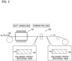
- a method for manufacturing the clad material 30 making up the chassis 3 according to the embodiment of the present invention is now described with reference to FIGS. 2 to 6 .
- a strip-shaped Cu plate 132 made of Cu or a Cu alloy is prepared. Then, soft annealing is performed on the Cu plate 132 using an annealing furnace 101 in which the internal temperature is set to a temperature exceeding the recrystallization temperature (220°C, for example) of the Cu or Cu alloy making up the Cu plate 132. Thus, the Cu plate 132 is in a state in which the internal strain due to work-hardening is removed and the structure is sufficiently softened.
- temper rolling is performed on the Cu plate 132 that has undergone the soft annealing using a roller 102.
- the Cu plate 132 accumulates internal stress (strain) and is work-hardened.
- the number of temper rolling passes can be selected as appropriate.
- the temper rolling is preferably performed in such a manner that the thickness t14 of the Cu plate 132 after the temper rolling is 60% or more and less than 100% of the thickness t14 of the Cu plate 132 before the temper rolling.
- the ductility of SUS plates 131 and 133 made of stainless steel having high MECHANICAL STRENGTH and low ductility and the ductility of a Cu plate 132 made of Cu or a Cu alloy having low mechanical strength and high ductility can be close to each other.
- the thickness t14 of the Cu plate 132 after the temper rolling is set to 60% or more of the thickness t14 of the Cu plate 132 before the temper rolling such that grain coarsening of the Cu layer 32 of the clad material 30 can be easily significantly reduced or prevented.
- the prepared Cu plate 132 has been work-hardened by being subjected to the temper rolling after the annealing.
- the strip-shaped SUS plate 131 and the strip-shaped SUS plate 133 made of stainless steel are prepared. Furthermore, both the SUS plates 131 and 133 are sufficiently annealed.
- the thickness of the SUS plate 131, the thickness of the Cu plate 132 that has undergone the temper rolling, and the thickness of the SUS plate 133 are appropriately selected according to the thickness ratios (t2avg:t4:t3avg) of the SUS layer 31, the Cu layer 32, and the SUS layer 33 in the clad material 30 to be produced.
- the clad rolling is performed to roll and bond the sufficiently annealed SUS plate 131, the Cu plate 132 that has undergone the temper rolling after the annealing, and the sufficiently annealed SUS plate 133 using a roller 103 in a state in which the same are stacked in this order.
- a pressure-bonded material 130 having a thickness of 1.0 mm or less or 0.5 mm or less, for example, in which the SUS plate 131, the Cu plate 132, and the SUS plate 133 have been bonded (roll-bonded) to each other in a state in which the same are stacked in this order, is produced.
- the number of clad rolling passes can be selected as appropriate.
- the roller 103 includes a pair of work rollers 103a and a pair of work rollers 103b, four bearings 103c that respectively hold shafts of the work rollers 103a and 103b, and a pair of load cells 103d attached to the bearings 103c of the work rollers 103a on the Z1 side, for example.
- the pair of load cells 103d have a function of detecting a force (resultant force) P0 (N) that acts on the work rollers 103a from the SUS plate 131, the Cu plate 132, and the SUS plate 133 (rolled material) by detecting the strain caused by the force (resultant force) that acts on the work rollers 103a.
- the thickness of the pressure-bonded material on the exit side of the roller can be calculated from values such as a pressure-bonding load, a plate width, a roll force function, and deformation resistance. Therefore, the pressure-bonding load is determined such that it is possible to set various conditions for obtaining a desired plate thickness according to the used rolling mill. Furthermore, the plate thickness is equal to the sum of the deformation of the rolling mill due to the pressure-bonding load and the roll setting position of the rolling mill. Therefore, in order to obtain a desired plate thickness, the plate thickness can be adjusted by changing the roll setting position.
- a rational rolling plan is associated with a pressure-bonding load.
- the pressure-bonding load can be calculated from various conditions such as a thickness before rolling and a roll radius, and thus a rational rolling plan can be made without prescribing other conditions by determining the pressure-bonding load in advance.
- a pressure-bonding load P in the clad rolling is set to 4.4 ⁇ 10 3 N/mm or more.
- the pressure-bonding load P (N/mm) can be obtained as an estimate from the following formula (2).
- P Qp ⁇ k ⁇ ⁇ R ⁇ h 1 ⁇ h 2 / L
- the roll force function magnification compared with ideal deformation
- the average deformation resistance an average stress required for deformation between the rollers in a two-dimensional deformation state in the case in which the deformation in the width direction is ignored
- k N/mm 2
- the radii of the work rollers 103a (103b) are R (mm)
- the total thickness of the SUS plate 131, the Cu plate 132, and the SUS plate 133 (rolled material) on the entrance side of the roller 103 is h1 (mm)
- the thickness of the pressure-bonded material 130 on the exit side of the roller 103 is h2 (mm).
- the pressure-bonding load P is preferably 4.9 ⁇ 10 3 N/mm or more, more preferably 6.0 ⁇ 10 3 N/mm or more, and still more preferably and 6.8 ⁇ 10 3 N/mm or more.
- the pressure-bonding load P it is preferable to set the pressure-bonding load P to 4.4 ⁇ 10 3 N/mm or more and a value in the vicinity of 4.4 ⁇ 10 3 N/mm.
- the thickness t12 of the SUS plate 131 and the thickness t13 of the SUS plate 133 are varied along the rolling direction. Consequently, there are portions of the SUS plates 131 and 133 respectively having a minimum thickness t12min and a minimum thickness t13min due to a partial difference in thickness.
- the pressure-bonding load P in the clad rolling is set to 4.4 ⁇ 10 3 N/mm or more.
- the minimum thickness t12min of the SUS plate 131 in the stacking direction and the minimum thickness t13min of the SUS plate 133 in the stacking direction can be set to 84% or more and less than 100% of the average thickness t12avg of the SUS plate 131 in the stacking direction and the average thickness t13avg of the SUS plate 133 in the stacking direction, respectively.
- the minimum thickness t2min of the SUS layer 31 and the minimum thickness t3min of the SUS layer 33 can be 70% or more and less than 100% of the average thickness t2avg and the average thickness t3avg, respectively.
- the average thicknesses t12avg and t13avg of the SUS plates 131 and 133 may be obtained from a predetermined range (length) in the rolling direction of the clad material.
- the predetermined range (length) is not particularly limited as long as the same is in the range of one or more wavelengths of the wave of the interface formed in a wave shape, but is preferably at least about 15 mm from the viewpoint of measurement reliability.
- the average thickness t12avg of the SUS plate 131 is the average of the thickness t12 of the SUS plate 131 in the pressure-bonded material 130
- the average thickness t13avg of the SUS plate 133 is the average of the thickness t13 of the SUS plate 133 in the pressure-bonded material 130.
- the length of the pressure-bonded material 130 in the width direction may be adjusted by cutting an end of the pressure-bonded material 130 in the width direction using an end cutting machine 104. Then, the thickness of the pressure-bonded material 130 is adjusted by performing the intermediate rolling on the pressure-bonded material 130 using a roller 105. Thus, it is possible to reduce thickness variations in each pressure-bonded material 130 (clad material 30). The number of passes for intermediate rolling can be selected as appropriate.
- diffusion annealing is performed using an annealing furnace 106 in which the internal temperature is set to a temperature exceeding the recrystallization temperature of the stainless steel making up the SUS plate 131.
- the diffusion annealing under a temperature condition of 850°C or more and 1000°C or less.
- the clad material 30 including the SUS layer 31, the Cu layer 32 roll-bonded to the SUS layer 31, and the SUS layer 33 roll-bonded to the side of the Cu layer 32 opposite to the SUS layer 31 shown in FIG. 2 is produced.
- the manufacturing method according to the present invention is not limited to a method in which the steps from the clad rolling to the slit cutting in the finishing step are continuously performed.
- the average thickness of each layer is reduced in accordance with the rolling reduction, but the ratio of the average thickness of each layer is substantially equivalent and unchanged.
- the average thicknesses t12avg and t13avg may be obtained by measuring the thicknesses t2, t3, t12, and t13 at a plurality of portions (ten or more portions, for example) of the corresponding layers and plates and calculating the averages thereof.
- the thickness t14 (see FIG. 4 ) of the Cu plate 132 before the diffusion annealing (after the intermediate rolling) is preferably set to 20% or more of the thickness t14 (see FIG. 3 ) of the Cu plate 132 after the soft annealing (before the temper rolling).
- the grain size of the Cu or Cu alloy in the Cu layer 32 (the Cu plate 132 after the diffusion annealing) can be reduced to 150 ⁇ m or less. Consequently, the elongation of the clad material 30 is improved, and thus workability can be improved.
- the minimum thickness t2min of the SUS layer 31 in the stacking direction and the minimum thickness t3min of the SUS layer 33 in the stacking direction are set to 70% or more and less than 100% of the average thickness t2avg of the SUS layer 31 in the stacking direction and the average thickness t3avg of the SUS layer 33 in the stacking direction, respectively.
- the thicknesses t2 and t3 of the SUS layer 31 and the SUS layer 33 in the stacking direction are equalized, and thus the occurrence of portions having excessively small thicknesses (less than 70% of the average thicknesses) in the SUS layer 31 and the SUS layer 33 can be significantly reduced or prevented. Therefore, when the chassis 3 making up the clad material 30 is welded to another member, for example, welding of another member to the portion of the SUS layer 31 having an excessively small thickness t2 or the portion of the SUS layer 33 having an excessively small thickness t3 can be significantly reduced or prevented, and thus a decrease in welding strength due to insufficient welding can be significantly reduced or prevented.
- the clad material 30 includes the SUS layer 31 made of stainless steel, the Cu layer 32 made of Cu or a Cu alloy and roll-bonded to the SUS layer 31, and the SUS layer 33 made of stainless steel and roll-bonded to the side of the Cu layer 32 opposite to the SUS layer 31. Accordingly, in the clad material 30, its mechanical strength and corrosion resistance can be ensured by the SUS layer 31 and the SUS layer 33 made of stainless steel while its conductivity and thermal conductivity can be ensured by the Cu layer 32 made of Cu or a Cu alloy. Consequently, the clad material 30 suitable for the chassis 3 that also serves as a heat sink can be provided.
- the percentage of the standard deviation of the minimum thickness t2min of the SUS layer 31 with respect to the thickness t1 of the clad material 30 and the percentage of the standard deviation of the minimum thickness t3min of the SUS layer 33 with respect to the thickness t1 of the clad material 30 are preferably 1.5% or less. Accordingly, the minimum thickness t2min of the SUS layer 31 in the stacking direction and the minimum thickness t3min of the SUS layer 33 in the stacking direction are further equalized, and thus the occurrence of the portion having an excessively small thickness in the SUS layer 31 and the portion having an excessively small thickness in the SUS layer 33 (the portions having thicknesses of less than 70% of the average thicknesses) can be further significantly reduced or prevented.
- the occurrence of the portion having an excessively small thickness in the SUS layer 31 and the portion having an excessively small thickness in the SUS layer 33 can be further significantly reduced or prevented. Therefore, the decrease in the welding strength as described above can be further significantly reduced or prevented. Furthermore, the variations in the characteristics of the chassis 3 produced from the clad material 30 as described above can be further significantly reduced or prevented.
- the SUS layer 31 and the SUS layer 33 are preferably both made of austenitic stainless steel. Accordingly, the austenitic stainless steel and the Cu or Cu alloy are both non-magnetic such that the entire clad material 30 can be non-magnetic. Accordingly, the electronic components 4a, for example, can be prevented from being adversely affected due to magnetization of the chassis 3 made of the clad material 30 and also serving as a heat sink.
- the clad rolling is performed with a pressure-bonding load P of 4.4 ⁇ 10 3 N/mm or more.
- the clad rolling is performed with a sufficient pressure-bonding load P of 4.4 ⁇ 10 3 N/mm or more, and thus it is possible to significantly reduce or prevent each layer from being rolled in such a manner as to plastically deform non-uniformly due to a difference between the ductility of the SUS plate 131 and the SUS plate 133 made of stainless steel and the ductility of the Cu plate 132 made of Cu or a Cu alloy.
- the non-uniform thickness t2 of the SUS layer 31 in the stacking direction and the non-uniform thickness t3 of the SUS layer 33 in the stacking direction can both be significantly reduced or prevented, and thus in the cross-sectional view along the stacking direction (Z direction), the minimum thickness t2min of the SUS layer 31 in the stacking direction and the minimum thickness t3min of the SUS layer 33 in the stacking direction can be set to 70% or more and less than 100% of the average thickness t2avg of the SUS layer 31 in the stacking direction and the average thickness avg of the SUS layer 33 in the stacking direction, respectively. Therefore, the occurrence of the portion having an excessively small thickness in the SUS layer 31 or the SUS layer 33 made of stainless steel can be significantly reduced or prevented.
- the pressure-bonding load P is preferably set to 4.9 ⁇ 10 3 N/mm or more. Accordingly, the clad rolling can be performed with a more sufficient pressure-bonding load P, and thus it is possible to further significantly reduce or prevent each layer from being rolled in such a manner as to plastically deform non-uniformly.
- the prepared Cu plate 132 has been work-hardened by being subjected to the temper rolling after the annealing. Accordingly, as the Cu plate 132 made of Cu or a Cu alloy, a Cu plate 132, the mechanical strength (such as 0.2% proof stress) of which has been improved due to accumulation of the internal stress (strain), can be used. Consequently, the mechanical strength of the Cu plate 132, which is lower in mechanical strength than the SUS plate 131 and the SUS plate 133 made of stainless steel, can be closer to the mechanical strength of the SUS plate 131 and the SUS plate 133.
- the clad rolling can be performed on the metal plates having similar mechanical strength, and thus each layer is rolled in such a manner as to plastically deform more uniformly.
- the SUS plate 131, the Cu plate 132, and the SUS plate 133 can be sufficiently bonded to each other, and the thickness of each layer can be formed with a high degree of accuracy.
- the thickness of the prepared Cu plate 132 after the temper rolling is 60% or more and less than 100% of the thickness before the temper rolling. Accordingly, excessive accumulation of internal stress (strain) in the prepared Cu plate 132 due to the thickness of the prepared Cu plate 132 after the temper rolling of less than 60% of the thickness of the prepared Cu plate 132 before the temper rolling can be significantly reduced or prevented. Consequently, grain coarsening of the Cu layer 32 (Cu plate 132) due to large internal stress (strain) can be significantly reduced or prevented, and thus a decrease in the elongation (workability) of the clad material 30 due to the Cu layer 32 can be significantly reduced or prevented.
- the thicknesses (minimum thicknesses t ⁇ min) of portions of the SUS plates having the smallest thickness (thinnest portions) and the average values (average thicknesses t ⁇ avg) of the thicknesses of the SUS plates were acquired when the clad rolling was performed with different pressure-bonding loads P.
- pressure-bonded materials were produced by the manufacturing method shown in FIGS. 3 and 4 .
- a Cu plate 132 (second metal plate) made of oxygen-free copper (C1020, JIS standards) and having a thickness t14 of 0.5 mm was prepared.
- This Cu plate had a long strip shape in a rolling direction.
- soft annealing was performed on the Cu plate 132 at a temperature higher than the recrystallization temperature of Cu making up the Cu plate 132, and then temper rolling was performed.
- the thickness t14 of the Cu plate 132 after the temper rolling was set to 0.4 mm (80% of the thickness t14 before the temper rolling), and the Cu plate was work-hardened to some extent.
- a pair of SUS plates 131 and 133 (a first metal plate and a third metal plate) having a thickness of 0.2 mm, made of SUS316L (JIS standards), and commonly frequently used, were prepared.
- As the pair of SUS plates 131 and 133 sufficiently annealed SUS plates were used. Furthermore, the pair of SUS plates 131 and 133 had a long strip shape in the rolling direction.
- Prepared materials for the SUS plate 131 and the SUS plate 133 and the thicknesses thereof were the same, and thus the thickness ratios of the thickness (average thickness t12avg) of the SUS plate 131 and the thickness (average thickness t13avg) of the SUS plate 133 to the thickness of the pressure-bonded material 130 were substantially the same (25%).
- the SUS plate 131 and the SUS plate 133 can be collectively evaluated as SUS plates (the SUS plates 131 and 133) without distinguishing the SUS plate 131 from the SUS plate 133 in the pressure-bonded material 130.
- the clad rolling was performed in a state in which the SUS plate 131, the work-hardened Cu plate 132, and the SUS plate 133 were stacked in this order such that the strip-shaped pressure-bonded material 130 was produced.
- the rolling was performed such that the thickness t12 of the SUS plate 131, the thickness t14 of the Cu plate 132, and the thickness t13 of the SUS plate 133 after the clad rolling became 56% of the thickness t12, the thickness t14, and the thickness t13 before the clad rolling.
- the SUS plate 131, the work-hardened Cu plate 132, and the SUS plate 133 were roll-bonded under any one of pressure-bonding conditions 1 to 13 shown in TABLE 1. Then, a cross-section (see FIG. 4 ) of the pressure-bonded material 130 immediately after the clad rolling in the stacking direction (Z direction), which was a cross-section along the rolling direction, was observed such that the thickness (minimum thickness t12min) of the thinnest portion of the SUS plate 131 and the thickness (minimum thickness t13min) of the thinnest portion of the SUS plate 133 were acquired.
- the strip-shaped pressure-bonded material 130 produced with any one of thirteen types of pressure-bonding loads P (4.0 ⁇ 10 3 N/mm (pressure-bonding condition 1) or more and 7.8 ⁇ 10 3 N/mm (pressure-bonding condition 13) or less) shown in TABLE 1, ten test regions having a range (length) of 15 mm in the rolling direction were acquired. At this time, five portions were randomly acquired in the vicinity of each of opposite ends of the strip-shaped pressure-bonded material 130 in the rolling direction.
- the minimum thickness t12min of the SUS plate 131 and the minimum thickness t13min of the SUS plate 133 were acquired, the ten minimum thicknesses t12min and the ten minimum thicknesses t13min were collectively averaged, and the minimum thickness of the SUS plates (SUS plates 131 and 133) in the pressure-bonded material 130 was set to t ⁇ min. Therefore, the above minimum thickness t ⁇ min is based on measured values of twenty thicknesses obtained from the pressure-bonded material 130.
- the thicknesses of five randomly selected portions of the SUS plate 131 was measured and averaged to acquire the average thickness t12avg of the SUS plate 131.
- the thicknesses of five randomly selected portions of the SUS plate 133 were measured and averaged to acquire the average thickness t13avg of the SUS plate 133.
- the average thickness t12avg of the five portions and the average thickness t13avg of the five portions obtained from the ten test regions were collectively averaged to obtain the average thickness taavg of the SUS plates (SUS plates 131 and 133) of the pressure-bonded material 130. Therefore, the above average thickness t ⁇ avg is based on measured values of a hundred thicknesses obtained from the pressure-bonded material 130.
- FIGS. 7 and 8 show a portion of a cross-sectional photograph of the pressure-bonded material under the pressure-bonding condition 3 and a portion of a cross-sectional photograph of the pressure-bonded material under the pressure-bonding condition 13, respectively.
- three different portions of the same rolled material are stacked in the stacking direction.
- Evaluation criteria in TABLE 1 are determined based on whether or not the ratio of the minimum thicknesses to the average thicknesses of the SUS layers in a final product is 70% or more. For example, in a clad material having a thickness of 1 mm in which a layer thickness ratio of a SUS layer, a Cu layer, and a SUS layer is 1:2:1, the average thicknesses of the SUS layer 31 and the SUS layer 33 are 0.25 mm. When the ratio of the minimum thicknesses to the average thicknesses of the SUS layers in the final product of the clad material was 70% (0.175 mm), no crack was generated.
- the thickness ratios R ⁇ 1 shown in TABLE 1 were obtained by defining the thickness ratios R ⁇ 2 from another viewpoint (the minimum thicknesses t ⁇ min with respect to the entire clad material).
- the thickness ratios R ⁇ 2 are thickness ratios of the minimum thicknesses t ⁇ min to the average thicknesses t ⁇ avg of the SUS plates immediately after the clad rolling.
- the thickness ratios R ⁇ 1 and R ⁇ 2 shown in TABLE 1 are ratios at the stage during production of the final product.
- the values of the thicknesses of the entire clad materials and the thicknesses of the respective layers are different, but theoretically, the ratios of the thicknesses of the respective layers to the thicknesses of the entire clad materials do not change.
- the ratios of the minimum thicknesses to the average thicknesses do not change due to further rolling.
- variations occur in the rolling operation, and thus even when R ⁇ 2 at the stage during production of the final product is 70% or more, the evaluation of the clad materials in which the ratios of the minimum thicknesses to the average thicknesses of the SUS layers of the final product are less than 70% is ⁇ (unsuitable).
- the ratios of the minimum thicknesses to the average thicknesses of the SUS layers of the final product are highly likely to be 70% or more 70% by performing further rolling (intermediate rolling and finish rolling) after the clad rolling, and thus the evaluation of the clad materials is o (suitable).
- the variations in the minimum thicknesses are further increased by performing further rolling (intermediate rolling and finish rolling) after the clad rolling, and the minimum thicknesses of first layers and the minimum thicknesses of third layers in the clad materials as final products are conceivably less than 70% of the average thicknesses of the first layers and the average thicknesses of the third layers, respectively. Therefore, the pressure-bonding conditions 1 to 3 are marked with ⁇ (unsuitable) as their evaluation.
- the minimum thicknesses of the first layers and the minimum thicknesses of the third layers in the clad materials as final products are conceivably 70% or more of the average thicknesses of the first layers and the average thicknesses of the third layers, respectively. Therefore, the pressure-bonding conditions 4 to 13 are marked with o (suitable) as their evaluation.
- the values of the thickness ratio R ⁇ 1 and the thickness ratio R ⁇ 2 of the pressure-bonded material subjected to roll-bonding with a pressure-bonding load P of 6.7 ⁇ 10 3 N/mm or more under the pressure-bonding condition 10 were smaller than the values of R ⁇ 1 and R ⁇ 2 of the pressure-bonded material subjected to roll-bonding with a pressure-bonding load P of 6.0 ⁇ 10 3 N/mm or more under the pressure-bonding condition 9.
- a force P0 applied to the work rollers 103a is represented by the product of the pressure-bonding load P and the length L of the roller surface (see the above formula (1)). Therefore, when the length L of the roller surface is constant as in the first embodiment, the pressure-bonding load P and the force P0 applied to the work rollers 103a are in a proportional relationship. That is, as the pressure-bonding load P increases, the force P0 applied to the work rollers 103a also increases. From this viewpoint, the value of the thickness h2 of the pressure-bonded material 130 on the exit side of the roller 103 varied due to a variation in the force P0, and R ⁇ 1 and R ⁇ 2 conceivably happened to decrease under that influence.
- the thickness h2 of the pressure-bonded material 130 on the exit side of the roller 103 decreases, the plastic deformation ratio of each layer increases. Accordingly, it is difficult to obtain uniformity of the thickness h2 of the pressure-bonded material 130 on the exit side of the roller 103, and it is also difficult to obtain uniformity of the thickness of each layer. Consequently, it is difficult to obtain uniformity of the thickness h2, the thickness ratio R ⁇ 1, and the thickness ratio R ⁇ 2 of the pressure-bonded material 130 on the exit side of the roller 103, and the values may vary and may be small or large.
- the pressure-bonding load is increased such that the thickness ratio R ⁇ 1 and the thickness ratio R ⁇ 2 themselves gradually increase.
- the tendency of a change of the value of R ⁇ 1 of the pressure-bonded material with respect to the pressure-bonding load P shown in TABLE 1 can be generally represented by a linear approximation curve having a slope of about 0.87 and an intercept of about 17.5 (a straight line suitable for data having a simple linear relationship).
- the tendency of a change of the value of R ⁇ 2 of the pressure-bonded material with respect to the pressure-bonding load P shown in TABLE 1 can be generally represented by a linear approximation curve having a slope of about 3.46 and an intercept of about 69.8.
- the degree (the magnitude of the undulation) of the wave shape of the interface is clearly different between the pressure-bonded material with ⁇ (unsuitable) as the evaluation and the pressure-bonded material with o (suitable) as the evaluation.
- the degree of the wave shape of the interface when the minimum thickness with respect to the average thickness in the pressure-bonded material is small (the values of the thickness ratios R ⁇ 2 and R ⁇ 2 are small), the amplitude of the wave at the interface increases, and thus it is known that the degree of the wave shape of the interface becomes larger (more wavy). In other words, the degree of the wave shape of the interface is improved by increasing the pressure-bonding load.
- Materials for a SUS plate 131 and a SUS plate 133 and the thicknesses thereof in the pressure-bonded material 130 were the same, and thus the thickness ratios of the thickness (average thickness t2avg) of a SUS layer 31 and the thickness (average thickness t3avg) of a SUS layer 33 to the thickness of the clad material 30 obtained by rolling the pressure-bonded material 130 were substantially the same (25%).
- the SUS layers (SUS layers 31 and 33) can be collectively evaluated without distinguishing the SUS layer 31 from the SUS layer 33 in the clad material 30.
- the thickness (minimum thickness t2min) of a portion having the smallest thickness (thinnest portion) in the SUS layer 31 (first layer) of the clad material 30 and the thickness (minimum thickness t3min) of a portion having the smallest thickness (thinnest portion) in the SUS layer 33 (third metal plate) of the clad material 30 were measured, and the thickness (minimum thickness t ⁇ min) of the portion having the smallest thickness (thinnest portion) in the SUS layers and the average value (average thickness t ⁇ avg) of the thicknesses of the SUS layers were acquired.
- the rolling was performed such that the thickness t11 of the pressure-bonded material 130 after the intermediate rolling was 67% of the thickness t11 of the pressure-bonded material 130 before the intermediate rolling.
- the strip-shaped clad material 30 of an example of the present invention was produced. Fourteen strip-shaped clad materials 30 of the example of the present invention were prepared.
- a clad material of a comparative example with respect to the example of the present invention was produced. Specifically, a strip-shaped Cu plate made of Cu or a Cu alloy and having a sufficiently softened structure was prepared. Note that temper rolling was not performed on the strip-shaped Cu plate.
- clad rolling was performed by rolling and bonding using a roller such that a pressure-bonded material was produced.
- roll-bonding was performed with a pressure-bonding load P of 4.3 ⁇ 10 3 N/mm (the pressure-bonding condition 3 in the first example).
- a change (rolling reduction) in the thickness of the pressure-bonded material before and after the clad rolling in the comparative example was the same as that in the example of the present invention.
- each of the fourteen clad materials of the example of the present invention and the fifteen clad materials of the comparative example ten test regions having a range (length) of 15 mm in a rolling direction were acquired. At this time, five portions were randomly acquired in the vicinity of each of opposite ends of the strip-shaped pressure-bonded material in the rolling direction. Then, in each of the ten test regions, the minimum thickness t2min of the SUS layer 31 and the minimum thickness t3min of the SUS layer 33 were acquired, the ten minimum thicknesses t2min and the ten minimum thicknesses t3min were collectively averaged, and the minimum thickness of the SUS layers (SUS layers 31 and 33) in the clad material 30 was set to t ⁇ min. Therefore, the above minimum thickness t ⁇ min is based on measured values of twenty thicknesses obtained from the clad material.
- the thicknesses of five randomly selected portions in the SUS layer 31 were measured and averaged to acquire the average thickness t2avg of the SUS layer 31.
- the thicknesses of five randomly selected portions in the SUS layer 33 were measured and averaged to acquire the average thickness t3avg of the SUS layer 33.
- the five average thicknesses t2avg and the five average thicknesses t3avg obtained from the ten test regions were collectively averaged to obtain the average thickness t ⁇ avg of the SUS layer (SUS layers 31 and 33) of the clad material 30. Therefore, the above average thickness t ⁇ avg is based on measured values of a hundred thicknesses obtained from the clad material 30.
- FIGS. 9 and 10 show a boxplot of the example of the present invention and a boxplot of the comparative example, respectively.
- the bar graph of the example of the present invention and the bar graph of the comparative example are shown in FIGS. 11 and 12 , respectively.
- the average value R ⁇ 1avg of R ⁇ 1 was 21.2% (see FIG. 11 ). Furthermore, as shown in FIG. 9 , it has been confirmable that in the clad material, R ⁇ 1 is 17.5% or more and R ⁇ 2 is 70.0% or more.
- the clad material of the example of the present invention it has been confirmable that the occurrence of portions having an excessively small thickness in the SUS layers (the first layer and the third layer) made of stainless steel is significantly reduced or prevented. Furthermore, it has been confirmable that in each clad material, the first quartile of R ⁇ 1 is 20% or more and the first quartile of R ⁇ 2 is 80.0% or more. From these, it has been confirmable that in many clad materials, the occurrence of portions having an excessively small thickness in the SUS layers can be reliably significantly reduced or prevented.
- the standard deviation ⁇ of R ⁇ 1 in the clad material of the example of the present invention was 1.0% (1.5% or less), and a variation in R ⁇ 1 was small.
- the average value R ⁇ 1avg of R ⁇ 1 was 18.8% (see FIG. 12 ). Furthermore, as shown in FIG. 10 , it has been confirmable that in the clad material, a part of R ⁇ 1 is less than 17.5% and a part of R ⁇ 2 is less than 70.0%.
- the SUS layers (the first layer and the third layer) made of stainless steel include portions having excessively small thicknesses.
- the SUS layers (the first layer and the third layer) made of stainless steel include portions having excessively small thicknesses.
- the standard deviation ⁇ of R ⁇ 1 in the clad material of the comparative example was 1.7% (a value exceeding 1.5%), and a variation in R ⁇ 1 was large.
- R ⁇ 1 and R ⁇ 2 in the pressure-bonded material under the pressure-bonding condition 4 of the first example were respectively the same as R ⁇ 1 and R ⁇ 2 in the pressure-bonded material under the pressure-bonding condition 6 (produced with a pressure-bonding load within the scope of the present invention (claim 4)). Therefore, even when R ⁇ 1 and R ⁇ 2 are measured similarly to the aforementioned second example using the pressure-bonded material under the pressure-bonding condition 4, it can be inferred that results having substantially no difference from R ⁇ 1 and R ⁇ 2 in the measurement of the second example performed using the pressure-bonded material under the pressure-bonding condition 6 are obtained.
- R ⁇ 1 is 17.5% or more
- R ⁇ 2 is 70.0% or more
- the standard deviation ⁇ of R ⁇ 1 is 1.0% (1.5% or less).
- the degree of the wave shape of the interface is smaller than when R ⁇ 1 and R ⁇ 2 are small. Therefore, as described above, even when a variation in the minimum thickness is further increased by performing further rolling (intermediate rolling and finish rolling) after the clad rolling, it can be inferred that when R ⁇ 1 and R ⁇ 2 are large, R ⁇ 1 and R ⁇ 2 also become large in the clad material as the final product. Furthermore, it can be inferred that the standard deviation ⁇ of R ⁇ 1 becomes small due to the small degree of the wave shape of the interface.
- R ⁇ 1 is 17.5% or more and R ⁇ 2 is 70.0% or more, and it can be inferred that the standard deviation ⁇ of R ⁇ 1 is less than 1.7% (probably 1.5% or less).
- the minimum thickness of the first layer in the stacking direction and the minimum thickness of the third layer in the stacking direction are 70% or more and less than 100% (the thickness ratio R ⁇ 2 is 70% or more and less than 100%) of the average thickness of the first layer in the stacking direction and the average thickness of the third layer in the stacking direction, respectively, it is possible to significantly reduce or prevent a decrease in welding strength when the clad material is welded to another member, and to significantly reduce or prevent the occurrence of a variation in the mechanical strength of the clad material.
- the pressure-bonding load at the time of clad rolling at which the thickness ratio R ⁇ 2 in the final product is 70% or more and less than 100% a numerical range from 4.6 ⁇ 10 3 N/mm to 7.8 ⁇ 10 3 N/mm is obtained.
- the pressure-bonding load is set to 4.4 ⁇ 10 3 N/mm such that the minimum thickness of the first layer in the stacking direction and the minimum thickness of the third layer in the stacking direction are highly likely to be 70% or more of the average thickness of the first layer in the stacking direction and the average thickness of the third layer in the stacking direction.
- the pressure-bonding conditions 1 to 3 were marked with ⁇
- the pressure-bonding conditions 4 to 13 were marked with o.
- the thickness ratio R ⁇ 2 after the finish rolling was obtained for the comparative example of the pressure-bonding condition 3 (pressure-bonding load: 4.3 ⁇ 10 3 N/mm) with the largest thickness ratio R ⁇ 2 (the minimum thickness of the SUS Layers) among the conditions marked with ⁇ in the first example and the example of the pressure-bonding condition 6 (pressure-bonding load: 4.9 ⁇ 10 3 N/mm) with the smallest thickness ratio R ⁇ 2 (the minimum thickness of the SUS Layers) among the conditions marked with o in the first example.
- the thickness ratios R ⁇ 2 after the finish rolling in all the test materials were 70% or more, while in the comparative example, portions in which the thickness ratio R ⁇ 2 after the finish rolling was less than 70% occurred in all the test materials.
- the thickness ratio R ⁇ 2 the minimum thickness of the SUS layers after the finish rolling is smaller than that of the pressure-bonding condition 3. Therefore, in TABLE 1, the pressure-bonding condition 3 is ⁇ , and thus both the pressure-bonding conditions 1 and 2 are also ⁇ .
- the grain size of a Cu layer was measured for the clad materials of the example of the present invention and the comparative example in the second example based on a comparison method of JIS H 0501. Furthermore, a tensile strength test based on JIS Z 2241 was performed on the clad materials of the example of the present invention and the comparative example such that tensile strength (a force at break) and 0.2% proof stress (a force when the elongation was 0.2%) as mechanical strength and elongation (((length at break - length before test)/length before test) ⁇ 100(%)) as workability were measured. As magnetic characteristics, the relative magnetic permeability of the clad materials of the example of the present invention and the comparative example was measured.
- the clad material of the example of the present invention in which the grain size of the Cu layer was 0.150 mm or less (0.108 mm) showed an elongation of 13.5%, which was a value of 10% or more. That is, it can be said that the clad material of the example of the present invention has sufficient workability (deformability).
- the clad material of the comparative example in which the grain size of the Cu layer exceeded 0.250 mm the elongation was 5.3%, which was a value of less than 10%. That is, the clad material of the comparative example may not have sufficient workability. Consequently, it can be said that the grain size of the Cu layer is set to 0.150 mm or less such that sufficient workability can be imparted to the clad material.
- the clad material of the example of the present invention can be used for a structure such as a chassis.
- the relative magnetic permeability as the magnetic characteristics did not differ greatly between the example of the present invention and the comparative example, and it has been confirmable that each of the examples hardly magnetizes.
- other components electroly affected due to magnetization of the chassis when the clad material of the example of the present invention is used for the chassis that also serves as a heat sink, for example.
- the clad material 30 has a three-layer structure in which the SUS layer 31 (first layer) made of stainless steel, the Cu layer 32 (second layer) made of Cu or a Cu alloy, and the SUS layer 33 (third layer) made of stainless steel are stacked in this order has been shown in the aforementioned embodiment, the present invention is not restricted to this.
- the clad material may have a four-or-more-layer structure as long as the same includes the first layer made of stainless steel, the second layer made of Cu or a Cu alloy and roll-bonded to the first layer, and the third layer made of stainless steel and roll-bonded to the side of the second layer opposite to the first layer.
- the present invention is not restricted to this.
- at least the temper rolling and the clad rolling may be performed, and the intermediate rolling and the finish rolling may not be performed.
- the thickness of the pressure-bonded material (pressure-bonded material 130) after the clad rolling is the same as that of the clad material (clad material 30) as a final product.
- the clad material (clad material 30) as a final product has a thickness level of 1.0 mm or less, 0.5 mm or less, 0.3 mm or less, or even 0.2 mm or less, for example.
- the temper rolling is performed.
- the present invention is not restricted to this.
- the clad material may be used for applications other than the chassis of the portable device.
- the clad material according to the present invention may be used for a conductive member of a battery.
- the clad material according to the present invention is suitable for applications in which it is necessary to satisfy one or both of mechanical strength and corrosion resistance and one or both of conductivity and heat conductivity.
Landscapes
- Engineering & Computer Science (AREA)
- Mechanical Engineering (AREA)
- Chemical & Material Sciences (AREA)
- Materials Engineering (AREA)
- Metallurgy (AREA)
- Organic Chemistry (AREA)
- Physics & Mathematics (AREA)
- Thermal Sciences (AREA)
- Crystallography & Structural Chemistry (AREA)
- Pressure Welding/Diffusion-Bonding (AREA)
- Metal Rolling (AREA)
- Laminated Bodies (AREA)
Claims (6)
- Plattiertes Material (30), umfassend:eine erste Schicht (31), gebildet aus rostfreiem Stahl;eine zweite Schicht (32), die aus Cu oder einer Cu-Legierung gebildet und mit der ersten Schicht walzverbunden ist; undeine dritte Schicht (33), die aus rostfreiem Stahl gebildet und mit einer der ersten Schicht abgewandten Seite der zweiten Schicht walzverbunden ist; wobeidas plattierte Material eine Gesamtdicke von 1 mm oder weniger aufweist; undin einer Querschnittsansicht entlang einer Stapelrichtung eine minimale Dicke der ersten Schicht in der Stapelrichtung und eine minimale Dicke der dritten Schicht in der Stapelrichtung 70% oder mehr und weniger als 100% einer durchschnittlichen Dicke der ersten Schicht in der Stapelrichtung bzw. einer durchschnittlichen Dicke der dritten Schicht in der Stapelrichtung beträgt,die Korngröße der zweiten Schicht (32) 0,150 mm oder weniger, bestimmt gemäß JIS H 0501, beträgt.
- Plattiertes Material gemäß Anspruch 1, wobei ein Prozentsatz einer Standardabweichung der minimalen Dicke der ersten Schicht bezogen auf eine Dicke des plattierten Materials und ein Prozentsatz einer Standardabweichung der minimalen Dicke der dritten Schicht bezogen auf die Dicke des plattierten Materials 1,5% oder weniger beträgt.
- Plattiertes Material gemäß Anspruch 1 oder 2, wobei die erste Schicht und die dritte Schicht beide aus austenitischem rostfreiem Stahl gebildet sind.
- Verfahren zur Herstellung eines plattierten Materials (30), umfassend:das Walzplattieren zum Walzen und Verbinden einer ersten Metallplatte (131), gebildet aus rostfreiem Stahl, einer zweiten Metallplatte (132), gebildet aus Cu oder einer Cu-Legierung, und einer dritten Metallplatte (133), gebildet aus rostfreiem Stahl, in einem Zustand, in dem die erste Metallplatte, die zweite Metallplatte und die dritte Metallplatte in dieser Reihenfolge gestapelt sind; wobeidas Walzplattierten mit einer Druckverbindungslast von 4,4 × 10³ N/mm oder mehr durchgeführt wird, so dass das plattierte Material, enthaltend eine erste Schicht (31), gebildet aus rostfreiem Stahl, eine zweite Schicht (32), die aus Cu oder einer Cu-Legierung gebildet und mit der ersten Schicht walzverbunden ist, und eine dritte Schicht (33), die aus rostfreiem Stahl gebildet und mit einer der ersten Schicht abgewandten Seite der zweiten Schicht walzverbunden ist, wobei das plattierte Material eine Gesamtdicke von 1 mm oder weniger aufweist, worin in einer Querschnittsansicht entlang einer Stapelrichtung eine minimale Dicke der ersten Schicht in der Stapelrichtung und eine minimale Dicke der dritten Schicht in der Stapelrichtung 70% oder mehr und weniger als 100% einer durchschnittlichen Dicke der ersten Schicht in der Stapelrichtung bzw. einer durchschnittlichen Dicke der dritten Schicht in der Stapelrichtung beträgt, hergestellt wird, wobei die zweite Metallplatte (132) durch Nachwalzen nach dem Glühen kaltverfestigt worden ist.
- Verfahren zur Herstellung eines plattierten Materials gemäß Anspruch 4, bei dem die Druckverbindungslast auf 4,9 × 10³ N/mm oder mehr eingestellt wird.
- Verfahren zur Herstellung eines plattierten Materials gemäß Anspruch 4 oder 5, bei dem das Nachwalzen so durchgeführt wird, dass die Dicke der zweiten Metallplatte nach dem Nachwalzen 60% oder mehr und weniger als 100% der Dicke der zweiten Metallplatte vor dem Nachwalzen beträgt.
Applications Claiming Priority (2)
| Application Number | Priority Date | Filing Date | Title |
|---|---|---|---|
| JP2017154136A JP6358378B1 (ja) | 2017-08-09 | 2017-08-09 | クラッド材の製造方法 |
| PCT/JP2018/020405 WO2019031027A1 (ja) | 2017-08-09 | 2018-05-28 | クラッド材およびクラッド材の製造方法 |
Publications (3)
| Publication Number | Publication Date |
|---|---|
| EP3666441A1 EP3666441A1 (de) | 2020-06-17 |
| EP3666441A4 EP3666441A4 (de) | 2021-04-21 |
| EP3666441B1 true EP3666441B1 (de) | 2023-08-09 |
Family
ID=62904845
Family Applications (1)
| Application Number | Title | Priority Date | Filing Date |
|---|---|---|---|
| EP18845236.1A Active EP3666441B1 (de) | 2017-08-09 | 2018-05-28 | Verkleidungsmaterial und verfahren zur herstellung von verkleidungsmaterial |
Country Status (6)
| Country | Link |
|---|---|
| US (2) | US11607867B2 (de) |
| EP (1) | EP3666441B1 (de) |
| JP (1) | JP6358378B1 (de) |
| KR (1) | KR102496226B1 (de) |
| CN (1) | CN110997211B (de) |
| WO (1) | WO2019031027A1 (de) |
Families Citing this family (3)
| Publication number | Priority date | Publication date | Assignee | Title |
|---|---|---|---|---|
| CN111918746B (zh) * | 2018-03-29 | 2022-06-17 | 古河电气工业株式会社 | 包层材料及其制造方法 |
| KR102286363B1 (ko) * | 2019-12-20 | 2021-08-05 | 주식회사 포스코 | 두께 편차가 균일한 클래드 박판의 제조방법 |
| KR102601845B1 (ko) * | 2021-11-09 | 2023-11-15 | 주식회사 디에스피 | 차량용 스피커 그릴 및 그 제조 방법 |
Family Cites Families (24)
| Publication number | Priority date | Publication date | Assignee | Title |
|---|---|---|---|---|
| JPS5410646B1 (de) | 1969-05-19 | 1979-05-09 | ||
| US3923558A (en) * | 1974-02-25 | 1975-12-02 | Olin Corp | Copper base alloy |
| US3985589A (en) * | 1974-11-01 | 1976-10-12 | Olin Corporation | Processing copper base alloys |
| DE3506524A1 (de) * | 1985-02-25 | 1986-08-28 | Akzo Gmbh, 5600 Wuppertal | Flexible polyimid-mehrschichtlaminate |
| JPH05161985A (ja) * | 1991-12-13 | 1993-06-29 | Nippon Steel Corp | 複合電磁鋼板の製造方法 |
| US6783870B2 (en) * | 2000-10-16 | 2004-08-31 | Engineered Materials Solutions, Inc. | Self-brazing materials for elevated temperature applications |
| JP2003105500A (ja) * | 2001-09-26 | 2003-04-09 | Nippon Metal Ind Co Ltd | ステンレス鋼/銅クラッドおよびその製造方法 |
| JP2005134073A (ja) | 2003-10-31 | 2005-05-26 | Denso Corp | プレート式熱交換器 |
| JP4916646B2 (ja) | 2004-01-09 | 2012-04-18 | 新日本製鐵株式会社 | 固体高分子型燃料電池セパレータ用クラッド板およびその製造方法 |
| JP2008123964A (ja) * | 2006-11-15 | 2008-05-29 | Hitachi Cable Ltd | 高強度・高導電性クラッド材及びその製造方法 |
| CN201105358Y (zh) * | 2007-09-07 | 2008-08-27 | 中国联合工程公司 | 一种金属带材的热复合装置 |
| US20100233506A1 (en) * | 2007-09-26 | 2010-09-16 | Furukawa Electric Co., Ltd. | Silver-coated composite material for movable contact and method for manufacturing the same |
| CN102917870B (zh) * | 2010-06-02 | 2016-04-20 | 新日铁住金株式会社 | 包层材料 |
| JP5306418B2 (ja) | 2010-07-09 | 2013-10-02 | 日新製鋼株式会社 | 銅被覆鋼箔、負極用電極及び電池 |
| WO2013125623A1 (ja) * | 2012-02-24 | 2013-08-29 | 株式会社神戸製鋼所 | 銅合金 |
| CN103858529B (zh) * | 2012-07-10 | 2016-09-07 | 日立金属株式会社 | 底板和底板的制造方法 |
| CN202895810U (zh) * | 2012-09-04 | 2013-04-24 | 无锡银荣板业有限公司 | 铜/不锈钢/铜多层复合材料结构 |
| KR20140066413A (ko) * | 2012-11-23 | 2014-06-02 | 한국기계연구원 | 상온 접합력이 향상된 클래드 판재의 제조방법 및 이를 통해 제조된 클래드 판재 |
| CN102974611B (zh) * | 2012-11-28 | 2015-07-08 | 上海实达精密不锈钢有限公司 | 一种柔性太阳能电池基板不锈钢精密钢带成型方法 |
| CN103538313A (zh) * | 2012-12-03 | 2014-01-29 | 黎汉东 | 一种新型热轧钛-铝-不锈钢复合板及其生产方法和用途 |
| JP5965418B2 (ja) * | 2014-01-09 | 2016-08-03 | 株式会社日立金属ネオマテリアル | シャーシおよび携帯機器 |
| CN103736729B (zh) * | 2014-01-22 | 2015-07-29 | 太原科技大学 | 一种轧制制备金属复合板带的方法 |
| KR101653742B1 (ko) * | 2015-06-19 | 2016-09-06 | 주식회사 한국클래드텍 | 클래드판의 연속 제조 방법 및 장치 |
| JP6609590B2 (ja) * | 2017-03-30 | 2019-11-20 | Jx金属株式会社 | 層状組織を有する高強度チタン銅条および箔 |
-
2017
- 2017-08-09 JP JP2017154136A patent/JP6358378B1/ja active Active
-
2018
- 2018-05-28 EP EP18845236.1A patent/EP3666441B1/de active Active
- 2018-05-28 CN CN201880048287.1A patent/CN110997211B/zh active Active
- 2018-05-28 WO PCT/JP2018/020405 patent/WO2019031027A1/ja not_active Ceased
- 2018-05-28 US US16/634,228 patent/US11607867B2/en active Active
- 2018-05-28 KR KR1020207000405A patent/KR102496226B1/ko active Active
-
2022
- 2022-02-28 US US17/681,996 patent/US11981107B2/en active Active
Also Published As
| Publication number | Publication date |
|---|---|
| CN110997211A (zh) | 2020-04-10 |
| EP3666441A1 (de) | 2020-06-17 |
| WO2019031027A1 (ja) | 2019-02-14 |
| KR102496226B1 (ko) | 2023-02-06 |
| US20210086478A1 (en) | 2021-03-25 |
| US11607867B2 (en) | 2023-03-21 |
| KR20200038925A (ko) | 2020-04-14 |
| JP6358378B1 (ja) | 2018-07-18 |
| CN110997211B (zh) | 2023-01-10 |
| JP2019031036A (ja) | 2019-02-28 |
| US11981107B2 (en) | 2024-05-14 |
| EP3666441A4 (de) | 2021-04-21 |
| US20220176676A1 (en) | 2022-06-09 |
Similar Documents
| Publication | Publication Date | Title |
|---|---|---|
| US11981107B2 (en) | Method for manufacturing clad material | |
| US10953630B2 (en) | Method for manufacturing clad material | |
| EP0060083B1 (de) | Titanplattiertes Stahlblech | |
| EP2853614B1 (de) | Duplexedelstahlrohr und verfahren zur herstellung davon | |
| KR20010062057A (ko) | 내리징성 및 성형성이 우수한 페라이트계 스테인리스강판및 그 제조방법 | |
| EP3339461A1 (de) | Edelstahlfolie | |
| EP4506474A1 (de) | Stahlblech, element und verfahren zur herstellung davon | |
| EP3623487B1 (de) | Titanblech | |
| CN110690403B (zh) | 电池用引线部件和电池用引线部件的制造方法 | |
| Utsunomiya et al. | Necking condition of layers in clad sheets during rolling | |
| EP3473346B1 (de) | Verfahren zum kaltwalzen eines stahlblechs und verfahren zur herstellung eines stahlblechs | |
| JP6645490B2 (ja) | クラッド材およびクラッド材の製造方法 | |
| CN115210399A (zh) | 包层钢板及其制造方法以及焊接结构物 | |
| Kato et al. | Strength-Electrical Conductivity Balances of Cu/Martensite Steel Multilayered Sheets with Various Volume Ratios | |
| EP3276048A1 (de) | Elektrisch leitfähiges material für verbindungskomponente | |
| JP2014128813A (ja) | 化成処理性及びプレス成形性に優れた鋼板の製造方法 | |
| JP2008123964A (ja) | 高強度・高導電性クラッド材及びその製造方法 | |
| Beganović et al. | EFFECT OF UNEVEN PLASTIC DEFORMATION ON WIDTH OF CLAD LAYERS OF EXPLOSIVE WELDED THREE-LAYERS STRIP | |
| JP2019098536A (ja) | クラッド材およびクラッド材の製造方法 | |
| CN118475467A (zh) | 复合板 | |
| JP5326097B2 (ja) | 界面剥離破断、ネッキング破断のない強度−延性バランスにすぐれた複層鋼 | |
| JP5512224B2 (ja) | 異形断面条材の製造方法 | |
| WO2024202153A1 (ja) | ニッケルクラッド板、及びその製造方法 | |
| EP4667602A1 (de) | Nichtorientiertes elektrostahlblech, motorkern und motor | |
| JP2019112718A (ja) | 積層薄板の製造方法及び積層薄板 |
Legal Events
| Date | Code | Title | Description |
|---|---|---|---|
| STAA | Information on the status of an ep patent application or granted ep patent |
Free format text: STATUS: THE INTERNATIONAL PUBLICATION HAS BEEN MADE |
|
| PUAI | Public reference made under article 153(3) epc to a published international application that has entered the european phase |
Free format text: ORIGINAL CODE: 0009012 |
|
| STAA | Information on the status of an ep patent application or granted ep patent |
Free format text: STATUS: REQUEST FOR EXAMINATION WAS MADE |
|
| 17P | Request for examination filed |
Effective date: 20200122 |
|
| AK | Designated contracting states |
Kind code of ref document: A1 Designated state(s): AL AT BE BG CH CY CZ DE DK EE ES FI FR GB GR HR HU IE IS IT LI LT LU LV MC MK MT NL NO PL PT RO RS SE SI SK SM TR |
|
| AX | Request for extension of the european patent |
Extension state: BA ME |
|
| DAV | Request for validation of the european patent (deleted) | ||
| DAX | Request for extension of the european patent (deleted) | ||
| A4 | Supplementary search report drawn up and despatched |
Effective date: 20210319 |
|
| RIC1 | Information provided on ipc code assigned before grant |
Ipc: B23K 20/04 20060101AFI20210315BHEP Ipc: B21B 1/22 20060101ALI20210315BHEP Ipc: B32B 15/01 20060101ALI20210315BHEP Ipc: C22C 9/00 20060101ALI20210315BHEP Ipc: C22C 38/40 20060101ALI20210315BHEP Ipc: C21D 1/26 20060101ALI20210315BHEP Ipc: B23K 103/22 20060101ALN20210315BHEP |
|
| RIC1 | Information provided on ipc code assigned before grant |
Ipc: B23K 103/22 20060101ALN20230118BHEP Ipc: C21D 1/26 20060101ALI20230118BHEP Ipc: C22C 38/40 20060101ALI20230118BHEP Ipc: C22C 9/00 20060101ALI20230118BHEP Ipc: B32B 15/01 20060101ALI20230118BHEP Ipc: B21B 1/22 20060101ALI20230118BHEP Ipc: B23K 20/04 20060101AFI20230118BHEP |
|
| GRAP | Despatch of communication of intention to grant a patent |
Free format text: ORIGINAL CODE: EPIDOSNIGR1 |
|
| STAA | Information on the status of an ep patent application or granted ep patent |
Free format text: STATUS: GRANT OF PATENT IS INTENDED |
|
| RIC1 | Information provided on ipc code assigned before grant |
Ipc: B23K 103/22 20060101ALN20230130BHEP Ipc: C21D 1/26 20060101ALI20230130BHEP Ipc: C22C 38/40 20060101ALI20230130BHEP Ipc: C22C 9/00 20060101ALI20230130BHEP Ipc: B32B 15/01 20060101ALI20230130BHEP Ipc: B21B 1/22 20060101ALI20230130BHEP Ipc: B23K 20/04 20060101AFI20230130BHEP |
|
| INTG | Intention to grant announced |
Effective date: 20230301 |
|
| RAP3 | Party data changed (applicant data changed or rights of an application transferred) |
Owner name: PROTERIAL, LTD. |
|
| P01 | Opt-out of the competence of the unified patent court (upc) registered |
Effective date: 20230411 |
|
| GRAS | Grant fee paid |
Free format text: ORIGINAL CODE: EPIDOSNIGR3 |
|
| GRAA | (expected) grant |
Free format text: ORIGINAL CODE: 0009210 |
|
| STAA | Information on the status of an ep patent application or granted ep patent |
Free format text: STATUS: THE PATENT HAS BEEN GRANTED |
|
| AK | Designated contracting states |
Kind code of ref document: B1 Designated state(s): AL AT BE BG CH CY CZ DE DK EE ES FI FR GB GR HR HU IE IS IT LI LT LU LV MC MK MT NL NO PL PT RO RS SE SI SK SM TR |
|
| REG | Reference to a national code |
Ref country code: GB Ref legal event code: FG4D |
|
| REG | Reference to a national code |
Ref country code: CH Ref legal event code: EP |
|
| REG | Reference to a national code |
Ref country code: DE Ref legal event code: R096 Ref document number: 602018055170 Country of ref document: DE |
|
| REG | Reference to a national code |
Ref country code: IE Ref legal event code: FG4D |
|
| REG | Reference to a national code |
Ref country code: LT Ref legal event code: MG9D |
|
| REG | Reference to a national code |
Ref country code: NL Ref legal event code: MP Effective date: 20230809 |
|
| REG | Reference to a national code |
Ref country code: AT Ref legal event code: MK05 Ref document number: 1596932 Country of ref document: AT Kind code of ref document: T Effective date: 20230809 |
|
| PG25 | Lapsed in a contracting state [announced via postgrant information from national office to epo] |
Ref country code: GR Free format text: LAPSE BECAUSE OF FAILURE TO SUBMIT A TRANSLATION OF THE DESCRIPTION OR TO PAY THE FEE WITHIN THE PRESCRIBED TIME-LIMIT Effective date: 20231110 |
|
| PG25 | Lapsed in a contracting state [announced via postgrant information from national office to epo] |
Ref country code: IS Free format text: LAPSE BECAUSE OF FAILURE TO SUBMIT A TRANSLATION OF THE DESCRIPTION OR TO PAY THE FEE WITHIN THE PRESCRIBED TIME-LIMIT Effective date: 20231209 |
|
| PG25 | Lapsed in a contracting state [announced via postgrant information from national office to epo] |
Ref country code: SE Free format text: LAPSE BECAUSE OF FAILURE TO SUBMIT A TRANSLATION OF THE DESCRIPTION OR TO PAY THE FEE WITHIN THE PRESCRIBED TIME-LIMIT Effective date: 20230809 Ref country code: RS Free format text: LAPSE BECAUSE OF FAILURE TO SUBMIT A TRANSLATION OF THE DESCRIPTION OR TO PAY THE FEE WITHIN THE PRESCRIBED TIME-LIMIT Effective date: 20230809 Ref country code: PT Free format text: LAPSE BECAUSE OF FAILURE TO SUBMIT A TRANSLATION OF THE DESCRIPTION OR TO PAY THE FEE WITHIN THE PRESCRIBED TIME-LIMIT Effective date: 20231211 Ref country code: NO Free format text: LAPSE BECAUSE OF FAILURE TO SUBMIT A TRANSLATION OF THE DESCRIPTION OR TO PAY THE FEE WITHIN THE PRESCRIBED TIME-LIMIT Effective date: 20231109 Ref country code: NL Free format text: LAPSE BECAUSE OF FAILURE TO SUBMIT A TRANSLATION OF THE DESCRIPTION OR TO PAY THE FEE WITHIN THE PRESCRIBED TIME-LIMIT Effective date: 20230809 Ref country code: LV Free format text: LAPSE BECAUSE OF FAILURE TO SUBMIT A TRANSLATION OF THE DESCRIPTION OR TO PAY THE FEE WITHIN THE PRESCRIBED TIME-LIMIT Effective date: 20230809 Ref country code: LT Free format text: LAPSE BECAUSE OF FAILURE TO SUBMIT A TRANSLATION OF THE DESCRIPTION OR TO PAY THE FEE WITHIN THE PRESCRIBED TIME-LIMIT Effective date: 20230809 Ref country code: IS Free format text: LAPSE BECAUSE OF FAILURE TO SUBMIT A TRANSLATION OF THE DESCRIPTION OR TO PAY THE FEE WITHIN THE PRESCRIBED TIME-LIMIT Effective date: 20231209 Ref country code: HR Free format text: LAPSE BECAUSE OF FAILURE TO SUBMIT A TRANSLATION OF THE DESCRIPTION OR TO PAY THE FEE WITHIN THE PRESCRIBED TIME-LIMIT Effective date: 20230809 Ref country code: GR Free format text: LAPSE BECAUSE OF FAILURE TO SUBMIT A TRANSLATION OF THE DESCRIPTION OR TO PAY THE FEE WITHIN THE PRESCRIBED TIME-LIMIT Effective date: 20231110 Ref country code: FI Free format text: LAPSE BECAUSE OF FAILURE TO SUBMIT A TRANSLATION OF THE DESCRIPTION OR TO PAY THE FEE WITHIN THE PRESCRIBED TIME-LIMIT Effective date: 20230809 Ref country code: AT Free format text: LAPSE BECAUSE OF FAILURE TO SUBMIT A TRANSLATION OF THE DESCRIPTION OR TO PAY THE FEE WITHIN THE PRESCRIBED TIME-LIMIT Effective date: 20230809 |
|
| PG25 | Lapsed in a contracting state [announced via postgrant information from national office to epo] |
Ref country code: PL Free format text: LAPSE BECAUSE OF FAILURE TO SUBMIT A TRANSLATION OF THE DESCRIPTION OR TO PAY THE FEE WITHIN THE PRESCRIBED TIME-LIMIT Effective date: 20230809 |
|
| PG25 | Lapsed in a contracting state [announced via postgrant information from national office to epo] |
Ref country code: ES Free format text: LAPSE BECAUSE OF FAILURE TO SUBMIT A TRANSLATION OF THE DESCRIPTION OR TO PAY THE FEE WITHIN THE PRESCRIBED TIME-LIMIT Effective date: 20230809 |
|
| PG25 | Lapsed in a contracting state [announced via postgrant information from national office to epo] |
Ref country code: SM Free format text: LAPSE BECAUSE OF FAILURE TO SUBMIT A TRANSLATION OF THE DESCRIPTION OR TO PAY THE FEE WITHIN THE PRESCRIBED TIME-LIMIT Effective date: 20230809 Ref country code: RO Free format text: LAPSE BECAUSE OF FAILURE TO SUBMIT A TRANSLATION OF THE DESCRIPTION OR TO PAY THE FEE WITHIN THE PRESCRIBED TIME-LIMIT Effective date: 20230809 Ref country code: ES Free format text: LAPSE BECAUSE OF FAILURE TO SUBMIT A TRANSLATION OF THE DESCRIPTION OR TO PAY THE FEE WITHIN THE PRESCRIBED TIME-LIMIT Effective date: 20230809 Ref country code: EE Free format text: LAPSE BECAUSE OF FAILURE TO SUBMIT A TRANSLATION OF THE DESCRIPTION OR TO PAY THE FEE WITHIN THE PRESCRIBED TIME-LIMIT Effective date: 20230809 Ref country code: DK Free format text: LAPSE BECAUSE OF FAILURE TO SUBMIT A TRANSLATION OF THE DESCRIPTION OR TO PAY THE FEE WITHIN THE PRESCRIBED TIME-LIMIT Effective date: 20230809 Ref country code: CZ Free format text: LAPSE BECAUSE OF FAILURE TO SUBMIT A TRANSLATION OF THE DESCRIPTION OR TO PAY THE FEE WITHIN THE PRESCRIBED TIME-LIMIT Effective date: 20230809 Ref country code: SK Free format text: LAPSE BECAUSE OF FAILURE TO SUBMIT A TRANSLATION OF THE DESCRIPTION OR TO PAY THE FEE WITHIN THE PRESCRIBED TIME-LIMIT Effective date: 20230809 |
|
| REG | Reference to a national code |
Ref country code: DE Ref legal event code: R097 Ref document number: 602018055170 Country of ref document: DE |
|
| PG25 | Lapsed in a contracting state [announced via postgrant information from national office to epo] |
Ref country code: IT Free format text: LAPSE BECAUSE OF FAILURE TO SUBMIT A TRANSLATION OF THE DESCRIPTION OR TO PAY THE FEE WITHIN THE PRESCRIBED TIME-LIMIT Effective date: 20230809 |
|
| PLBE | No opposition filed within time limit |
Free format text: ORIGINAL CODE: 0009261 |
|
| STAA | Information on the status of an ep patent application or granted ep patent |
Free format text: STATUS: NO OPPOSITION FILED WITHIN TIME LIMIT |
|
| 26N | No opposition filed |
Effective date: 20240513 |
|
| PG25 | Lapsed in a contracting state [announced via postgrant information from national office to epo] |
Ref country code: SI Free format text: LAPSE BECAUSE OF FAILURE TO SUBMIT A TRANSLATION OF THE DESCRIPTION OR TO PAY THE FEE WITHIN THE PRESCRIBED TIME-LIMIT Effective date: 20230809 |
|
| PG25 | Lapsed in a contracting state [announced via postgrant information from national office to epo] |
Ref country code: BG Free format text: LAPSE BECAUSE OF FAILURE TO SUBMIT A TRANSLATION OF THE DESCRIPTION OR TO PAY THE FEE WITHIN THE PRESCRIBED TIME-LIMIT Effective date: 20230809 |
|
| PG25 | Lapsed in a contracting state [announced via postgrant information from national office to epo] |
Ref country code: BG Free format text: LAPSE BECAUSE OF FAILURE TO SUBMIT A TRANSLATION OF THE DESCRIPTION OR TO PAY THE FEE WITHIN THE PRESCRIBED TIME-LIMIT Effective date: 20230809 |
|
| REG | Reference to a national code |
Ref country code: CH Ref legal event code: PL |
|
| PG25 | Lapsed in a contracting state [announced via postgrant information from national office to epo] |
Ref country code: MC Free format text: LAPSE BECAUSE OF FAILURE TO SUBMIT A TRANSLATION OF THE DESCRIPTION OR TO PAY THE FEE WITHIN THE PRESCRIBED TIME-LIMIT Effective date: 20230809 |
|
| PG25 | Lapsed in a contracting state [announced via postgrant information from national office to epo] |
Ref country code: LU Free format text: LAPSE BECAUSE OF NON-PAYMENT OF DUE FEES Effective date: 20240528 |
|
| GBPC | Gb: european patent ceased through non-payment of renewal fee |
Effective date: 20240528 |
|
| PG25 | Lapsed in a contracting state [announced via postgrant information from national office to epo] |
Ref country code: MC Free format text: LAPSE BECAUSE OF FAILURE TO SUBMIT A TRANSLATION OF THE DESCRIPTION OR TO PAY THE FEE WITHIN THE PRESCRIBED TIME-LIMIT Effective date: 20230809 Ref country code: LU Free format text: LAPSE BECAUSE OF NON-PAYMENT OF DUE FEES Effective date: 20240528 Ref country code: CH Free format text: LAPSE BECAUSE OF NON-PAYMENT OF DUE FEES Effective date: 20240531 |
|
| REG | Reference to a national code |
Ref country code: BE Ref legal event code: MM Effective date: 20240531 |
|
| PG25 | Lapsed in a contracting state [announced via postgrant information from national office to epo] |
Ref country code: IE Free format text: LAPSE BECAUSE OF NON-PAYMENT OF DUE FEES Effective date: 20240528 |
|
| PG25 | Lapsed in a contracting state [announced via postgrant information from national office to epo] |
Ref country code: BE Free format text: LAPSE BECAUSE OF NON-PAYMENT OF DUE FEES Effective date: 20240531 |
|
| PG25 | Lapsed in a contracting state [announced via postgrant information from national office to epo] |
Ref country code: FR Free format text: LAPSE BECAUSE OF NON-PAYMENT OF DUE FEES Effective date: 20240531 |
|
| PG25 | Lapsed in a contracting state [announced via postgrant information from national office to epo] |
Ref country code: GB Free format text: LAPSE BECAUSE OF NON-PAYMENT OF DUE FEES Effective date: 20240528 |
|
| PGFP | Annual fee paid to national office [announced via postgrant information from national office to epo] |
Ref country code: DE Payment date: 20250402 Year of fee payment: 8 |
|
| PG25 | Lapsed in a contracting state [announced via postgrant information from national office to epo] |
Ref country code: CY Free format text: LAPSE BECAUSE OF FAILURE TO SUBMIT A TRANSLATION OF THE DESCRIPTION OR TO PAY THE FEE WITHIN THE PRESCRIBED TIME-LIMIT; INVALID AB INITIO Effective date: 20180528 |