EP3663429B1 - Anlage für die feuerverzinkung - Google Patents
Anlage für die feuerverzinkung Download PDFInfo
- Publication number
- EP3663429B1 EP3663429B1 EP20151616.8A EP20151616A EP3663429B1 EP 3663429 B1 EP3663429 B1 EP 3663429B1 EP 20151616 A EP20151616 A EP 20151616A EP 3663429 B1 EP3663429 B1 EP 3663429B1
- Authority
- EP
- European Patent Office
- Prior art keywords
- weight
- range
- flux
- amounts
- chloride
- Prior art date
- Legal status (The legal status is an assumption and is not a legal conclusion. Google has not performed a legal analysis and makes no representation as to the accuracy of the status listed.)
- Active
Links
Images

Classifications
-
- C—CHEMISTRY; METALLURGY
- C23—COATING METALLIC MATERIAL; COATING MATERIAL WITH METALLIC MATERIAL; CHEMICAL SURFACE TREATMENT; DIFFUSION TREATMENT OF METALLIC MATERIAL; COATING BY VACUUM EVAPORATION, BY SPUTTERING, BY ION IMPLANTATION OR BY CHEMICAL VAPOUR DEPOSITION, IN GENERAL; INHIBITING CORROSION OF METALLIC MATERIAL OR INCRUSTATION IN GENERAL
- C23C—COATING METALLIC MATERIAL; COATING MATERIAL WITH METALLIC MATERIAL; SURFACE TREATMENT OF METALLIC MATERIAL BY DIFFUSION INTO THE SURFACE, BY CHEMICAL CONVERSION OR SUBSTITUTION; COATING BY VACUUM EVAPORATION, BY SPUTTERING, BY ION IMPLANTATION OR BY CHEMICAL VAPOUR DEPOSITION, IN GENERAL
- C23C2/00—Hot-dipping or immersion processes for applying the coating material in the molten state without affecting the shape; Apparatus therefor
- C23C2/30—Fluxes or coverings on molten baths
-
- C—CHEMISTRY; METALLURGY
- C23—COATING METALLIC MATERIAL; COATING MATERIAL WITH METALLIC MATERIAL; CHEMICAL SURFACE TREATMENT; DIFFUSION TREATMENT OF METALLIC MATERIAL; COATING BY VACUUM EVAPORATION, BY SPUTTERING, BY ION IMPLANTATION OR BY CHEMICAL VAPOUR DEPOSITION, IN GENERAL; INHIBITING CORROSION OF METALLIC MATERIAL OR INCRUSTATION IN GENERAL
- C23C—COATING METALLIC MATERIAL; COATING MATERIAL WITH METALLIC MATERIAL; SURFACE TREATMENT OF METALLIC MATERIAL BY DIFFUSION INTO THE SURFACE, BY CHEMICAL CONVERSION OR SUBSTITUTION; COATING BY VACUUM EVAPORATION, BY SPUTTERING, BY ION IMPLANTATION OR BY CHEMICAL VAPOUR DEPOSITION, IN GENERAL
- C23C2/00—Hot-dipping or immersion processes for applying the coating material in the molten state without affecting the shape; Apparatus therefor
- C23C2/003—Apparatus
- C23C2/0038—Apparatus characterised by the pre-treatment chambers located immediately upstream of the bath or occurring locally before the dipping process
-
- C—CHEMISTRY; METALLURGY
- C23—COATING METALLIC MATERIAL; COATING MATERIAL WITH METALLIC MATERIAL; CHEMICAL SURFACE TREATMENT; DIFFUSION TREATMENT OF METALLIC MATERIAL; COATING BY VACUUM EVAPORATION, BY SPUTTERING, BY ION IMPLANTATION OR BY CHEMICAL VAPOUR DEPOSITION, IN GENERAL; INHIBITING CORROSION OF METALLIC MATERIAL OR INCRUSTATION IN GENERAL
- C23C—COATING METALLIC MATERIAL; COATING MATERIAL WITH METALLIC MATERIAL; SURFACE TREATMENT OF METALLIC MATERIAL BY DIFFUSION INTO THE SURFACE, BY CHEMICAL CONVERSION OR SUBSTITUTION; COATING BY VACUUM EVAPORATION, BY SPUTTERING, BY ION IMPLANTATION OR BY CHEMICAL VAPOUR DEPOSITION, IN GENERAL
- C23C2/00—Hot-dipping or immersion processes for applying the coating material in the molten state without affecting the shape; Apparatus therefor
- C23C2/02—Pretreatment of the material to be coated, e.g. for coating on selected surface areas
- C23C2/024—Pretreatment of the material to be coated, e.g. for coating on selected surface areas by cleaning or etching
-
- C—CHEMISTRY; METALLURGY
- C23—COATING METALLIC MATERIAL; COATING MATERIAL WITH METALLIC MATERIAL; CHEMICAL SURFACE TREATMENT; DIFFUSION TREATMENT OF METALLIC MATERIAL; COATING BY VACUUM EVAPORATION, BY SPUTTERING, BY ION IMPLANTATION OR BY CHEMICAL VAPOUR DEPOSITION, IN GENERAL; INHIBITING CORROSION OF METALLIC MATERIAL OR INCRUSTATION IN GENERAL
- C23C—COATING METALLIC MATERIAL; COATING MATERIAL WITH METALLIC MATERIAL; SURFACE TREATMENT OF METALLIC MATERIAL BY DIFFUSION INTO THE SURFACE, BY CHEMICAL CONVERSION OR SUBSTITUTION; COATING BY VACUUM EVAPORATION, BY SPUTTERING, BY ION IMPLANTATION OR BY CHEMICAL VAPOUR DEPOSITION, IN GENERAL
- C23C2/00—Hot-dipping or immersion processes for applying the coating material in the molten state without affecting the shape; Apparatus therefor
- C23C2/04—Hot-dipping or immersion processes for applying the coating material in the molten state without affecting the shape; Apparatus therefor characterised by the coating material
- C23C2/06—Zinc or cadmium or alloys based thereon
-
- C—CHEMISTRY; METALLURGY
- C23—COATING METALLIC MATERIAL; COATING MATERIAL WITH METALLIC MATERIAL; CHEMICAL SURFACE TREATMENT; DIFFUSION TREATMENT OF METALLIC MATERIAL; COATING BY VACUUM EVAPORATION, BY SPUTTERING, BY ION IMPLANTATION OR BY CHEMICAL VAPOUR DEPOSITION, IN GENERAL; INHIBITING CORROSION OF METALLIC MATERIAL OR INCRUSTATION IN GENERAL
- C23C—COATING METALLIC MATERIAL; COATING MATERIAL WITH METALLIC MATERIAL; SURFACE TREATMENT OF METALLIC MATERIAL BY DIFFUSION INTO THE SURFACE, BY CHEMICAL CONVERSION OR SUBSTITUTION; COATING BY VACUUM EVAPORATION, BY SPUTTERING, BY ION IMPLANTATION OR BY CHEMICAL VAPOUR DEPOSITION, IN GENERAL
- C23C2/00—Hot-dipping or immersion processes for applying the coating material in the molten state without affecting the shape; Apparatus therefor
- C23C2/26—After-treatment
Definitions
- the present invention relates to the technical field of galvanizing iron-based or iron-containing components, in particular steel-based or steel-containing components (steel components), preferably for the automotive or motor vehicle industry, but also for other technical fields of application (e.g. for the construction industry, the field of general mechanical engineering, the electrical industry, etc.), by means of hot-dip galvanizing (hot-dip galvanizing).
- the present invention relates to the inventive use of a plant for hot-dip galvanizing (hot-dip galvanizing) according to claims 1-14.
- components made of steel for motor vehicles such as cars, trucks, commercial vehicles, etc., but also for other technical areas (e.g. construction industry, mechanical engineering, electrical industry, etc.), require efficient corrosion protection that can withstand long-term stress.
- galvanizing galvanizing
- the steel is provided with a generally thin zinc layer to protect the steel from corrosion.
- Various galvanizing processes can be used to galvanize steel components, i.e. to cover them with a metallic zinc coating, in particular hot-dip galvanizing (also known synonymously as hot-dip galvanizing), spray galvanizing (flame spraying with zinc wire), diffusion galvanizing (Sherard galvanizing), electrolytic galvanizing, non-electrolytic galvanizing using zinc flake coatings and mechanical galvanizing.
- hot-dip galvanizing also known synonymously as hot-dip galvanizing
- spray galvanizing flame spraying with zinc wire
- diffusion galvanizing Sherard galvanizing
- electrolytic galvanizing non-electrolytic galvanizing using zinc flake coatings and mechanical galvanizing.
- hot-dip galvanizing The most important method for protecting steel from corrosion using metallic zinc coatings is hot-dip galvanizing (hot-dip galvanizing).
- Steel is dipped continuously (e.g. strip and wire) or piece by piece (e.g. components) into a heated tank filled with liquid zinc at temperatures of around 450 °C to 600 °C (melting point of zinc: 419.5 °C), so that a resistant alloy layer of iron and zinc forms on the steel surface, and a very firmly adhering pure zinc layer forms on top of that.
- Hot-dip galvanizing has been a recognized and proven method for many years to protect parts and components made of iron materials, especially steel materials, from corrosion.
- the typically pre-cleaned or pre-treated component is immersed in a liquid-hot zinc bath, where it reacts with the molten zinc and, as a result, forms a relatively thin zinc layer that is metallurgically bonded to the base material.
- discontinuous batch galvanizing cf. e.g. DIN EN ISO 1461
- continuous strip and wire galvanizing cf. e.g. DIN EN 10143 and DIN EN 10346.
- Both batch galvanizing and strip and wire galvanizing are standardized processes.
- Continuously galvanized steel strip and continuously galvanized wire are each a preliminary or intermediate product (semi-finished product) which is further processed after galvanizing, in particular by forming, punching, cutting, etc., whereas components to be protected by batch galvanizing are first completely manufactured and only then hot-dip galvanized (which protects the components all around from corrosion).
- Batch galvanizing and strip/wire galvanizing also differ in terms of the thickness of the zinc layer, which results in different protection periods - also depending on the zinc layer.
- the zinc layer thickness of strip-galvanized sheets is usually a maximum of 20 to 25 micrometers, whereas the zinc layer thickness of batch-galvanized steel parts is usually in the range of 50 to 200 micrometers and even more.
- Hot-dip galvanizing provides both active and passive corrosion protection. Passive protection is provided by the barrier effect of the zinc coating. Active corrosion protection is provided by the cathodic effect of the zinc coating. Compared to more noble metals in the electrochemical series, such as iron, zinc serves as a sacrificial anode, which protects the iron underneath from corrosion until it is completely corroded itself.
- Conventional hot-dip galvanizing in particular dip galvanizing, is based in particular on dipping iron or steel components into a zinc melt to form a zinc coating or a zinc coating on the surface of the components.
- careful surface preparation of the components to be galvanized is generally required beforehand, which usually includes degreasing followed by rinsing, subsequent acid pickling followed by rinsing and finally flux treatment (i.e. so-called fluxing) followed by drying.
- aqueous alkaline or acidic degreasing agents can usually be used as degreasing agents.
- a rinsing process usually follows, typically by immersion in a water bath, in order to prevent degreasing agents from being carried over with the galvanized material into the subsequent process step of pickling, whereby this is particularly important when changing from alkaline degreasing to acidic pickling.
- pickling which is used in particular to remove inherent contaminants such as rust and scale from the steel surface.
- Pickling is usually carried out in diluted hydrochloric acid, whereby the duration of the pickling process depends, among other things, on the state of contamination (e.g. degree of rust) of the galvanized material and the acid concentration and temperature of the pickling bath.
- a rinsing process usually takes place after the pickling treatment.
- fluxing also known as flux treatment
- a flux typically comprises an aqueous solution of inorganic chlorides, most frequently a mixture of zinc chloride (ZnCl 2 ) and ammonium chloride (NH 4 Cl).
- ZnCl 2 zinc chloride
- NH 4 Cl ammonium chloride
- the purpose of the flux is to carry out a final, intensive, fine cleaning of the steel surface before the steel surface reacts with the molten zinc, to dissolve the oxide skin of the zinc surface and to prevent further oxidation of the steel surface until the galvanizing process.
- the flux is intended to increase the wettability between the steel surface and the molten zinc.
- drying usually follows in order to create a solid flux film on the steel surface and to remove adhering water, so that subsequent undesirable reactions (in particular the formation of water vapor) in the liquid zinc dip bath are avoided.
- the components pretreated in the above-mentioned manner are then hot-dip galvanized by immersing them in the liquid zinc melt.
- the zinc content of the melt is at least 98.0 wt.% in accordance with DIN EN ISO 1461.
- the item to be galvanized After the item to be galvanized has been immersed in the molten zinc, it remains in the zinc melt bath for a sufficient period of time, in particular until the item to be galvanized has assumed its temperature and is coated with a zinc layer.
- the surface of the zinc melt is cleaned of oxides, zinc ash, flux residues and the like, in particular, before the item to be galvanized is then pulled out of the zinc melt again.
- the component hot-dip galvanized in this way is then subjected to a cooling process (e.g. in air or in a water bath). Finally, any holding devices for the component, such as slings, tie wires or the like, are removed.
- a post-processing or post-treatment process can usually be carried out, which can be complex. This involves removing as much of the excess zinc bath residue as possible, particularly drips from the zinc solidifying on the edges, as well as oxide or ash residues that adhere to the component.
- One criterion for the quality of hot-dip galvanizing is the thickness of the zinc coating in ⁇ m (micrometers).
- the DIN EN ISO 1461 standard specifies the minimum values of the required coating thicknesses that must be delivered during batch galvanizing depending on the material thickness. In practice, the coating thicknesses are significantly higher than the minimum coating thicknesses specified in DIN EN ISO 1461. In general, zinc coatings produced by batch galvanizing have a thickness in the range of 50 to 200 micrometers and even more.
- a coating of iron/zinc alloy layers of various compositions forms on the steel part as a result of the mutual diffusion of the liquid zinc with the steel surface.
- a layer of zinc - also known as the pure zinc layer - remains on the top alloy layer, which corresponds in composition to the zinc melt. Due to the high temperatures during hot-dip dipping, a relatively brittle layer based on an alloy (mixed crystals) between iron and zinc initially forms on the steel surface, and only then does the pure zinc form on top of this. Zinc layer.
- the relatively brittle iron/zinc alloy layer improves the bond strength with the base material, but makes it more difficult to form the galvanized steel.
- Components hot-dip galvanized with a zinc/aluminium melt can therefore be easily formed, but still have improved corrosion protection properties - despite the significantly lower layer thickness compared to conventional hot-dip galvanizing with a virtually aluminum-free zinc melt.
- a zinc/aluminium alloy used in the hot-dip galvanizing bath has improved fluidity properties compared to pure zinc.
- zinc coatings produced by hot-dip galvanizing using such zinc/aluminium alloys have greater corrosion resistance (which is two to six times better than that of pure zinc), better appearance, improved formability and better paintability than zinc coatings formed from pure zinc.
- lead-free zinc coatings can also be produced using this technology.
- Such a hot-dip galvanizing process using a zinc/aluminium melt or using a zinc/aluminium hot-dip galvanizing bath is known, for example, from WO 2002/042512 A1 and the relevant publication equivalents to this patent family (e.g. EP 1 352 100 B1 , DE 601 24 767 T2 and US 2003/0219543 A1 ).
- Suitable fluxes for hot-dip galvanizing using zinc/aluminium molten baths are also disclosed there, since flux compositions for zinc/aluminium hot-dip galvanizing baths must be different from those for conventional hot-dip galvanizing with pure zinc.
- microZINQ ® process The process disclosed there can be used to produce corrosion protection coatings with very low layer thicknesses (generally well below 50 micrometers and typically in the range of 2 to 20 micrometers) and with very low weight and high cost efficiency, which is why the process described there is used commercially under the name microZINQ ® process.
- state-of-the-art hot-dip galvanizing processes which use a zinc/aluminium melt or a zinc/aluminium hot-dip galvanizing bath (such as WO 2002/042512 A1 ) Fluxes containing significant amounts of lead chloride to enable good wettability with respect to the flux treatment, as well as nickel chloride to ensure good temperature resistance of the flux, and possibly also other transition or heavy metal chlorides to achieve other desired properties.
- the pH value of the flux bath is generally adjusted in state-of-the-art hot-dip galvanizing processes using hydrochloric acid (hydrochloric acid), which may promote undesirable hydrogen embrittlement of the metal substrate to be treated.
- the formation of the zinc layer and its properties it has been shown that these can be significantly influenced by alloying elements in the zinc melt.
- One of the most important elements here is aluminum: It has been shown that with an aluminum content of just 100 ppm (weight-based) in the zinc melt, the appearance of the resulting zinc layer can be improved to a brighter, shinier appearance. As the aluminum content in the zinc melt increases up to 1,000 ppm (weight-based), this effect increases steadily.
- the disadvantage of using aluminum-alloyed or aluminum-containing zinc melts is that it is much more difficult to wet the iron or steel surface to be galvanized with the liquid-hot Zn/Al melt and the reaction between the Zn/Al melt and the iron or steel surface of the component to be treated is much more sensitive and difficult to handle due to the high affinity of aluminum to iron.
- the use of A suitable flux and preheating of the material to be galvanized are required so that the reaction between the melt and the base material and, with it, the formation of a homogeneous, closed zinc coating can take place.
- flux treatment In general, when using aluminum-alloyed or aluminum-containing zinc melts (Zn/Al melts), special fluxes are required for the flux treatment (flux treatment), which often contain heavy metal compounds (usually heavy metal chlorides) that are not always ecologically compatible or undesirable, in particular lead and/or nickel chloride, but possibly also cobalt, manganese, tin, antimony and/or bismuth chloride, which are required to ensure subsequent perfect hot-dip galvanizing, in particular without defects on the galvanized components.
- heavy metal compounds usually heavy metal chlorides
- the lead chloride is intended in particular to reduce the surface tension and in this way to improve the wettability of the component surface to be treated with the liquid Zn/Al melt, while the nickel chloride is intended to improve the temperature resistance of the flux, in particular with regard to the drying that usually follows the flux treatment.
- the EP 2 725 115 A1 a flux composition for treating a metallic surface, the flux composition comprising more than 40 and less than 70 wt.% zinc chloride, 10 to 30 wt.% ammonium chloride, more than 6 and less than 30 wt.% of a combination of at least two alkali metal chlorides including sodium chloride and potassium chloride, 0 to 2 wt.% lead chloride, and 0 to 15 wt.% tin chloride.
- the WO 95/04607 A1 a hot-dip galvanizing process for treating steel components, whereby an aqueous flux is applied to the steel components, the components are then preheated and exposed to a non-reducing atmosphere to dry the flux. Additional energy in the form of heat is supplied to the pretreated component, which exceeds the energy required to dry the flux, and the component is then fed into a molten zinc bath for hot-dip galvanizing.
- the DE 23 17 600 A1 relates to an aqueous flux solution for hot-dip galvanizing, which contains zinc chloride and optionally alkali chlorides.
- the flux solution contains aluminum chloride and/or hydrogen chloride and optionally a maximum of 4% by weight of ammonium chloride, based on the zinc chloride contained in the solution and the optionally contained alkali chlorides, and also known corrosion inhibitors.
- the EP 1 694 880 A2 an aqueous flux solution for hot-dip galvanizing steel components, wherein the flux solution contains 200 to 600 g/l zinc chloride and ammonium chloride, wherein the molar ratio between ammonium chloride and zinc chloride is 1.7 to 3.3 and wherein the flux solution contains 8 g/l to 80 g/l aluminum chloride (AlCl 3 ).
- the problem underlying the present invention therefore consists in providing a method for hot-dip galvanizing (hot-dip galvanizing), in particular of iron-based or iron-containing components, preferably steel-based or steel-containing components (steel components), using an aluminum-containing or aluminum-alloyed zinc melt and a corresponding system for carrying out this method and, in addition, a flux or flux bath that can be used in the process, wherein the previously described disadvantages of the prior art are to be avoided at least as far as possible or at least mitigated.
- such a process is to be provided which, compared to conventional hot-dip galvanizing processes using an aluminum-containing or aluminum-alloyed zinc melt, enables improved process economy and/or a more efficient, in particular more flexible and/or more reliable, in particular less error-prone process sequence and/or improved ecological compatibility.
- such a process should not require the use of significant amounts of heavy metal compounds, in particular heavy metal chlorides, such as lead and/or nickel chloride, but possibly also other heavy metal chlorides, such as cobalt, manganese, tin, antimony and/or bismuth chloride, as part of the flux treatment and thus have improved ecological compatibility, but nevertheless reliably ensure that the treated components are galvanized efficiently and without defects.
- heavy metal chlorides such as lead and/or nickel chloride
- other heavy metal chlorides such as cobalt, manganese, tin, antimony and/or bismuth chloride
- the present invention proposes the inventive use of a plant for hot-dip galvanizing iron or steel components according to claim 1; further, in particular special and/or advantageous embodiments of the inventive use are the subject of the relevant use subclaims (claims 2 to 14).
- the present invention is associated with a multitude of completely unexpected advantages, special features and surprising technical effects, the following description of which makes no claim to completeness, but illustrates the inventive character of the present invention:
- a flux i.e.
- a flux bath or a flux composition which even in the difficult-to-perform hot-dip galvanizing using aluminum-containing or aluminum-alloyed zinc melts does not require the presence of lead chloride (PbCl 2 ) and nickel chloride (NiCl 2 ) and preferably also dispenses with other transition metal chlorides in the flux, in particular in the flux bath or the flux composition, such as in particular cobalt chloride (CoCl 2 ), manganese chloride (MnCl 2 ), tin chloride (SnCl 2 ), bismuth chloride (BiCl 3 ) and antimony chloride (SbCl 3 ), without impairing the quality of the resulting hot-dip galvanizing layer.
- PbCl 2 lead chloride
- NiCl 2 nickel chloride
- other transition metal chlorides in the flux in particular in the flux bath or the flux composition, such as in particular cobalt chloride (CoCl 2 ), manganese chloride (MnCl 2 ), tin
- the present invention results in hot-dip galvanized layers that are completely free of defects and which also have improved corrosion protection properties and, in general, excellent, if not even improved, mechanical and other properties (e.g. optical properties such as gloss).
- the flux used according to the invention in particular the flux composition used according to the invention or the flux bath used according to the invention, contains at least one aluminum salt and/or at least one silver salt, in particular aluminum chloride (AlCl 3 ) and/or silver chloride (AgCl), preferably aluminum chloride (AlCl 3 ), preferably in very small amounts, which means that organic and/or inorganic impurities (such as suspended matter), which are still present, for example, from the upstream treatment steps despite rinsing processes and generally lead to the formation of defects during hot-dip galvanizing, can be discharged or precipitated, so that additional transition metal chlorides to improve the wetting behavior or other properties in the context of the flux used according to the invention, in particular the flux bath or flux composition, can be completely dispensed with.
- the efficiency of the process used according to the invention can be further improved: As explained in more detail below, the effects of the alcohol content in the The times required for drying the flux film in the flux bath can be significantly shortened and/or the drying temperatures can be significantly reduced. In addition, the filming and wetting with the flux is homogenized in this way.
- the present invention with regard to hot-dip galvanizing using aluminum-alloyed or aluminum-containing zinc melts, brings about significantly improved process economy and a more efficient, in particular more flexible and/or more reliable, in particular less error-prone process sequence as well as improved ecological compatibility, in particular due to the omission of lead chloride and nickel chloride and possibly other transition or heavy metal chlorides in the flux used, but also the alcohol content in the flux bath.
- the present invention can also be used in ecologically sensitive areas where transition and heavy metal compounds, in particular transition metal and heavy metal chlorides, are to be avoided.
- the present invention does not require the use of significant amounts of transition and heavy metal compounds, in particular transition and heavy metal chlorides, such as lead and/or nickel chloride, but possibly also other heavy metal chlorides, such as cobalt, manganese, tin, antimony and/or bismuth chloride, in the context of the flux treatment, but nevertheless reliably ensures that the treated components are galvanized efficiently and without defects.
- transition and heavy metal chlorides such as lead and/or nickel chloride
- other heavy metal chlorides such as cobalt, manganese, tin, antimony and/or bismuth chloride
- the hot-dip galvanized or hot-dip galvanized iron and steel components are also reflected directly in the process products that can be obtained, ie the hot-dip galvanized or hot-dip galvanized iron and steel components: These not only have improved mechanical and optical properties and improved corrosion protection properties, but are also completely free of defects, and this with relatively low layer thicknesses in relation to the hot-dip galvanized layer.
- no undesirable transition metals or heavy metals can be introduced from the flux into the ultimately resulting hot-dip galvanized layer, since transition metals or heavy metals can be completely avoided during the flux treatment according to the present invention.
- Transition metals or heavy metals are at most deliberately added or alloyed to the zinc melt or the hot-dip galvanizing bath in order to specifically adjust certain properties of the hot-dip galvanizing layer, but then in an ecologically compatible manner, since they are an integral part of the hot-dip galvanizing layer and are stored or incorporated therein as a solid alloy component.
- the individual ingredients or components of the flux composition used according to the invention and of the flux bath used according to the invention work together in a synergistic manner:
- the zinc chloride ensures very good coverage of the iron or steel surface, particularly due to the flat formation of the dried ZnCl 2 crystals.
- a sufficient amount of ammonium chloride is also added to the flux composition, which is deposited on the component surface and thermally decomposes to NH 3 and HCl at the moment of immersion in the zinc melt, so that the last oxide residues are removed from the component surface.
- alkali and/or alkaline earth salts in particular NaCl and/or KCl, are added, which raise the melting point of the flux composition and thus enable high and effective drying.
- silver or aluminum salt, in particular AgCl and/or AlCl 3 in the flux or flux composition leads to an increase in the purity of the flux or flux composition, since silver or aluminum salt, in particular AgCl and/or AlCl 3 , namely organic and/or inorganic impurities, such as suspended matter, which can be introduced from the upstream pretreatment steps despite repeated rinsing processes, are removed or precipitated in small quantities, but in Zn/Al melts in quantities large enough to form defects.
- impurities are germs or bacteria (e.g. carryover from degreasing) and phosphates and sulfates (e.g. carryover from pickling). The precipitation of these substances prevents transfer to the component surface and thus eliminates the source of incorrect galvanizing.
- the alcohol content allows even the smallest impurities to be dissolved in the flux (which, in the case of organic substances, are then precipitated by the aluminum or silver salt used, in particular AlCl 3 and/or AgCl), so that an improved cleaning effect is achieved.
- the alcohol content can shorten the time required to dry the flux film, particularly due to the lower evaporation point of alcohol compared to water. This leads to a significant improvement over the previous state of the art, in which the galvanizing cycle defines the maximum drying time and as a result, particularly with massive components, the drying time is often not sufficient to dry the flux film sufficiently.
- a completely dried flux film enables a clean reaction with the zinc melt without splashing due to evaporating residual water.
- Better drying also leads to less zinc ash, which reduces the risk of zinc ash adhering to the galvanized material (i.e. better galvanizing quality and less rework).
- Faster drying also means that the drying time and/or drying temperature can be reduced, which in turn means energy savings and/or an increase in productivity.
- the flux in the zinc bath also burns off more quickly (also due to the lower evaporation point), i.e. the energy of the zinc melt can flow directly into heating the component, which in turn leads to a faster and more effective galvanizing process.
- the proportion of alcohol used depends in particular on the aluminium content of the zinc melt used, on the required drying or preheating (which in turn depends on the component geometry, in particular the material thickness, whereby thicker components require longer drying times), on the zinc alloy used and on the thickness of the flux film applied, whereby thicker flux layers depend on the salt concentration, extraction speed, roughness of the steel surface, etc., require longer drying times), the degree of contamination of the material to be galvanized and the technical requirements of the plant (e.g. performance of the drying oven, timing of the galvanizing process, suction performance of the flux bath, etc.).
- hot-dip galvanized components pretreated with an alcohol-containing flux also show significantly longer service lives (up to 20% improvement in service life and even more) compared to hot-dip galvanized components pretreated with an otherwise identical flux (but without any alcohol content, i.e. purely aqueous).
- an efficient and ecologically compatible hot-dip galvanizing process can thus be provided, whereby the disadvantages of the prior art described above can be at least largely avoided or at least mitigated.
- the flux bath is adjusted to a defined and/or predetermined, in particular acidic pH value, in particular in the pH value range from 0 to 6.9, preferably in the pH value range from 0.5 to 6.5, preferably in the pH value range from 1 to 5.5, particularly preferably in the pH value range from 1.5 to 5, very particularly preferably in the pH value range from 2 to 4.5, even more preferably in the pH value range from 2 to 4.
- a defined and/or predetermined, in particular acidic pH value in particular in the pH value range from 0 to 6.9, preferably in the pH value range from 0.5 to 6.5, preferably in the pH value range from 1 to 5.5, particularly preferably in the pH value range from 1.5 to 5, very particularly preferably in the pH value range from 2 to 4.5, even more preferably in the pH value range from 2 to 4.
- the flux bath is adjusted to a defined and/or predetermined, in particular acidic pH value, wherein the pH value is adjusted using a preferably inorganic acid in combination with a preferably inorganic basic compound, in particular ammonia (NH 3 ).
- a preferably inorganic basic compound in particular ammonia (NH 3 )
- NH 3 ammonia
- the weight-related alcohol/water ratio can vary within wide ranges.
- the flux bath contains the alcohol/water mixture in a weight-related alcohol/water ratio in the range from 0.5:99.5 to 99:1, in particular in the range from 2:98 to 95:5, preferably in the range from 5:95 to 90:10, preferably in the range from 5:95 to 50:50, particularly preferably in the range from 5:95 to 45:55, very particularly preferably in the range from 5:95 to 50:50, even more preferably in the range from 10:90 to 30:70, based on the alcohol/water mixture.
- the flux bath contains the alcohol, based on the alcohol/water mixture, in an amount of at least 0.5 wt.%, in particular in an amount of at least 1 wt.%, preferably in an amount of at least 2 wt.%, particularly preferably in an amount of at least 3 wt.%, even more preferably in an amount of at least 4 wt.%.
- the flux bath contains the alcohol, based on the alcohol/water mixture, in an amount of up to 90 wt.%, in particular in an amount of up to 70 wt.%, preferably in an amount of up to 50 wt.%, particularly preferably in an amount of up to 30 wt.%, even more preferably in an amount of up to 25 wt.%.
- the alcohol of the alcohol/water mixture of the flux bath is a water-miscible and/or water-soluble alcohol.
- the alcohol of the alcohol/water mixture of the flux bath is an alcohol that forms an azeotropic mixture with water.
- the alcohol of the alcohol/water mixture of the flux bath is selected from the group of C 1 -C 4 alcohols and mixtures thereof.
- the alcohol of the alcohol/water mixture of the flux bath is selected from the group of linear or branched, saturated or unsaturated, aliphatic, cycloaliphatic or aromatic, primary, secondary or tertiary monohydric C 1 -C 4 alcohols.
- the alcohol of the alcohol/water mixture of the flux bath is selected from the group of methanol, ethanol, propan-1-ol, propan-2-ol, butan-1-ol, butan-2-ol and mixtures thereof.
- the flux bath can - in addition to the ingredients or components mentioned above - also contain at least one wetting agent and/or surfactant, in particular at least one ionic or non-ionic wetting agent and/or surfactant, preferably at least one non-ionic wetting agent and/or surfactant.
- the flux bath can contain the at least one wetting agent and/or surfactant in amounts of 0.0001 to 15 wt.%, preferably in amounts of 0.001 to 10 wt.%, preferably in amounts of 0.01 to 8 wt.%, even more preferably in amounts of 0.01 to 6 wt.%, very particularly preferably in amounts of 0.05 to 3 wt.%, even more preferably in amounts of 0.1 to 2 wt.%, based on the flux bath.
- the flux can contain the at least one wetting agent and/or surfactant in particular in amounts of 0.0001 to 10 vol.%, preferably in amounts of 0.001 to 8 vol.%, preferably in amounts of 0.01 to 5 vol.%, even more preferably in amounts of 0.01 to 5 vol.%, very particularly preferably in amounts of 0.05 to 3 vol.%, even more preferably in amounts of 0.1 to 2 vol.%, based on the flux bath.
- the flux bath may contain the flux composition in an amount of at least 150 g/l, in particular in an amount of at least 200 g/l, preferably in an amount of at least 250 g/l, preferably in an amount of at least 300 g/l, particularly preferably in an amount of at least 400 g/l, very particularly preferably in an amount of at least 450 g/l, even more preferably in an amount of at least 500 g/l, in particular calculated as the total salt content of the flux composition.
- the flux bath can contain the flux composition in an amount of 150 g/l to 750 g/l, in particular in an amount of 200 g/l to 700 g/l, preferably in an amount of 250 g/l to 650 g/l, preferably in an amount of 300 g/l to 625 g/l, particularly preferably in an amount of 400 g/l to 600 g/l, very particularly preferably in an amount of 450 g/l to 580 g/l, even more preferably in an amount of 500 g/l to 575 g/l, in particular calculated as the total salt content of the flux composition.
- the flux composition in an amount of 150 g/l to 750 g/l, in particular in an amount of 200 g/l to 700 g/l, preferably in an amount of 250 g/l to 650 g/l, preferably in an amount of 300 g/l to 625 g/l, particularly preferably in an amount of 400 g/l to 600 g/l, very
- the flux composition used according to the invention can contain an alkali and/or alkaline earth chloride as the alkali and/or alkaline earth salt of component (iii).
- the flux composition used according to the invention can contain as alkali and/or alkaline earth salt of component (iii) at least one alkali and/or alkaline earth salt of an alkali and/or alkaline earth metal from the group of lithium (Li), sodium (Na), potassium (K), rubidium (Rb), cesium (Cs), beryllium (Be), magnesium (Mg), calcium (Ca), strontium (Sr) and barium (Ba) and combinations thereof.
- the flux composition used according to the invention contains, as the alkali and/or alkaline earth salt of component (iii), at least two alkali and/or alkaline earth salts that are different from one another, in particular at least two alkali and/or alkaline earth salts of an alkali and/or alkaline earth metal from the group of lithium (Li), sodium (Na), potassium (K), rubidium (Rb), cesium (Cs), beryllium (Be), magnesium (Mg), calcium (Ca), strontium (Sr) and barium (Ba) and combinations thereof.
- the alkali and/or alkaline earth salt of component (iii) at least two alkali and/or alkaline earth salts that are different from one another, in particular at least two alkali and/or alkaline earth salts of an alkali and/or alkaline earth metal from the group of lithium (Li), sodium (Na), potassium (K), rubidium (Rb), cesium (Cs), bery
- the flux composition used according to the invention contains, as alkali and/or alkaline earth salt of component (iii), at least two different alkali salts, in particular two different alkali chlorides, preferably sodium chloride and potassium chloride, in particular with a sodium/potassium weight ratio in the range from 50:1 to 1:50, in particular in the range from 25:1 to 1:25, preferably in the range from 10:1 to 1:10.
- the flux composition used according to the invention is also completely free of cobalt chloride (CoCl 2 ), manganese chloride (MnCl 2 ), tin chloride (SnCl 2 ), bismuth chloride (BiCl 3 ) and antimony chloride (SbCl 3 ).
- the flux composition used according to the invention is completely free of lead chloride (PbCl 2 ), nickel chloride (NiCl 2 ), cobalt chloride (CoCl 2 ), manganese chloride (MnCl 2 ), tin chloride (SnCl 2 ), bismuth chloride (BiCl 3 ) and antimony chloride (SbCl 3 ) and/or if the flux composition is at least completely free of chlorides from the group of lead chloride (PbCl 2 ), nickel chloride (NiCl 2 ), cobalt chloride (CoCl 2 ), manganese chloride (MnCl 2 ), tin chloride (SnCl 2 ), bismuth chloride (BiCl 3 ) and antimony chloride (SbCl 3 ).
- the flux composition used according to the invention is completely free of salts and compounds of metals from the group of lead (Pb), nickel (Ni), cobalt (Co), manganese (Mn), tin (Sn), bismuth (Bi) and antimony (Sb).
- the flux composition used according to the invention apart from zinc chloride (ZnCl 2 ) and aluminum and/or silver salt, in particular silver chloride (AgCl) and/or aluminum chloride (AlCl 3 ), is completely free of salts and compounds of transition and heavy metals.
- the general procedure is that the flux treatment is carried out by bringing the iron or steel component into contact with the flux bath and/or the flux composition, in particular by dipping or spraying, preferably dipping.
- the iron or steel component is brought into contact with the flux bath and/or the flux composition, in particular dipped into the flux bath, for a period of 0.001 to 30 minutes, in particular 0.01 to 20 minutes, preferably 0.1 to 15 minutes, preferably 0.5 to 10 minutes, particularly preferably 1 to 5 minutes.
- the iron or steel component can be brought into contact with the flux bath and/or the flux composition, in particular dipped into the flux bath, for a period of up to 30 minutes, in particular up to 20 minutes, preferably up to 15 minutes, preferably up to 10 minutes, particularly preferably up to 5 minutes.
- the drying treatment is carried out at a temperature in the range from 50 to 400 °C, in particular in the range from 75 to 350 °C, preferably in the range from 100 to 300 °C, preferably in the range from 125 to 275 °C, particularly preferably in the range from 150 to 250 °C, and/or if the drying treatment is carried out at a temperature up to 400 °C, in particular up to 350 °C, preferably up to 300 °C, preferably up to 275 °C, particularly preferably up to 250 °C.
- the drying treatment is carried out in such a way that the surface of the iron or steel component has a temperature in the range of 100 to 300 °C, in particular in the range of 125 to 275 °C, preferably in the range of 150 to 250 °C, preferably in the range of 160 to 225 °C, particularly preferably in the range of 170 to 200 °C, during drying.
- the drying treatment can be carried out in the presence of and/or by means of air.
- the drying treatment can be carried out in at least one drying device, in particular in at least one oven.
- the aluminum-containing, in particular aluminum-alloyed zinc melt (“Zn/Al melt”) and/or the galvanizing bath has an amount of aluminum in the range from 0.0001 to 25 wt.%, in particular in the range from 0.001 to 20 wt.%, preferably in the range from 0.005 to 17.5 wt.%, preferably in the range from 0.01 to 15 wt.%, particularly preferably in the range from 0.02 to 12.5 wt.%, very particularly preferably in the range from 0.05 to 10 wt.%, even more preferably in the range from 0.1 to 8 wt.%, based on the aluminum-containing, in particular aluminum-alloyed zinc melt ("Zn/Al melt”) and/or the galvanizing bath.
- the aluminum-containing, in particular aluminum-alloyed zinc melt (“Zn/Al melt”) and/or the galvanizing bath can have an amount of zinc of at least 75 wt.%, in particular at least 80 wt.%, preferably at least 85 wt.%, preferably at least 90 wt.%, and optionally at least one further metal, in particular in amounts of up to 5 wt.% and/or in particular selected from the group of bismuth (Bi), lead (Pb), tin (Sn), nickel (Ni), silicon (Si), magnesium (Mg) and combinations thereof. All of the above-mentioned quantities are to be selected in such a way that a total of 100 wt.% results.
- the zinc melt used contains other alloy components or alloy metals in addition to aluminum, this can be used to specifically control the process:
- the presence of lead and bismuth in particular can reduce the surface tension and thus improve the wettability of the surface to be galvanized, while the presence of tin can improve the optical properties, in particular the gloss, of the resulting galvanizing layer, the presence of nickel can further reduce the layer thickness, the presence of silicon can extend the service life of the zinc bath container (e.g. steel kettle), and the presence of magnesium can improve the corrosion properties, in particular the corrosion resistance, of the resulting galvanizing layer.
- the aluminum-containing, in particular aluminum-alloyed zinc melt (“Zn/Al melt”) and/or the galvanizing bath can have a temperature in the range from 375 °C to 750 °C, in particular a temperature in the range from 380 °C to 700 °C, preferably a temperature in the range from 390 °C to 680 °C, even more preferably in the range from 395 °C to 675 °C.
- the hot-dip galvanizing step is carried out in such a way that the iron or steel component is dipped into the aluminum-containing, in particular aluminum-alloyed zinc melt ("Zn/Al melt”) and/or into the galvanizing bath, in particular dipped therein and moved, in particular for a period of time which is sufficient to ensure effective hot-dip galvanizing (hot-dip galvanizing), in particular for a period of time in the range of 0.0001 to 60 minutes, preferably in the range of 0.001 to 45 minutes, preferably in the range of 0.01 to 30 minutes, even more preferably in the range of 0.1 to 15 minutes.
- Zn/Al melt aluminum-alloyed zinc melt
- hot-dip galvanizing hot-dip galvanizing
- the aluminum-containing, in particular aluminum-alloyed zinc melt (“Zn/Al melt”) and/or the galvanizing bath can be contacted with and/or flushed or passed through at least one inert gas, in particular nitrogen.
- the iron or steel component to be treated may be a single product or a large number of individual products.
- a discontinuous process is preferred, although a continuous process is not excluded in principle.
- the iron or steel component can also be a long product, in particular a wire, pipe, sheet, coil material or the like.
- a continuous procedure is preferred, although a discontinuous procedure is not excluded in this respect either.
- the hot-dip galvanizing (hot-dip galvanizing) carried out can be followed by a cooling step, i.e. the hot-dip galvanized (hot-dip galvanized) iron or steel component can be subjected to a cooling treatment, optionally followed by a further post-processing and/or post-treatment step.
- a cooling step i.e. the hot-dip galvanized (hot-dip galvanized) iron or steel component can be subjected to a cooling treatment, optionally followed by a further post-processing and/or post-treatment step.
- the optional cooling step and/or the optional cooling treatment can in particular be carried out by means of air and/or in the presence of air, preferably to ambient temperature.
- the flux bath of the flux treatment device (E) is usually acidic.
- the flux bath is set to a defined and/or predetermined, in particular acidic pH value, in particular in the pH value range from 0 to 6.9, preferably in the pH value range from 0.5 to 6.5, preferably in the pH value range from 1 to 5.5, particularly preferably in the pH value range from 1.5 to 5, very particularly preferably in the pH value range from 2 to 4.5, even more preferably in the pH value range from 2 to 4.
- the flux bath is adjusted to a defined and/or predetermined, in particular acidic pH value, the pH value being adjusted by means of a preferably inorganic acid in combination with a preferably inorganic basic compound, in particular ammonia (NH 3 ).
- a defined and/or predetermined, in particular acidic pH value the pH value being adjusted by means of a preferably inorganic acid in combination with a preferably inorganic basic compound, in particular ammonia (NH 3 ).
- the flux bath used in the flux treatment device (E) its composition can vary within a wide range:
- the system is designed such that the flux bath contains the alcohol/water mixture in a weight-related alcohol/water ratio in the range from 0.5:99.5 to 99:1, in particular in the range from 2:98 to 95:5, preferably in the range from 5:95 to 90:10, preferably in the range from 5:95 to 50:50, particularly preferably in the range from 5:95 to 45:55, very particularly preferably in the range from 5:95 to 50:50, even more preferably in the range from 10:90 to 30:70, based on the alcohol/water mixture.
- the system used according to the invention is designed such that the flux bath contains the alcohol, based on the alcohol/water mixture, in an amount of at least 0.5 wt.%, in particular in an amount of at least 1 wt.%, preferably in an amount of at least 2 wt.%, particularly preferably in an amount of at least 3 wt.%, even more preferably in an amount of at least 4 wt.%.
- the system used according to the invention is designed such that the flux bath contains the alcohol, based on the alcohol/water mixture, in an amount of up to 90 wt.%, in particular in an amount of up to 70 wt.%, preferably in an amount of up to 50 wt.%, particularly preferably in an amount of up to 30 wt.%, even more preferably in an amount of up to 25 wt.%.
- the alcohol of the alcohol/water mixture of the flux bath is a water-miscible and/or water-soluble alcohol.
- the alcohol of the alcohol/water mixture of the flux bath is an alcohol that forms an azeotropic mixture with water.
- the alcohol of the alcohol/water mixture of the flux bath is selected from the group of linear or branched, saturated or unsaturated, aliphatic, cycloaliphatic or aromatic, primary, secondary or tertiary monohydric C 1 -C 4 alcohols.
- the system is designed such that the alcohol of the alcohol/water mixture of the flux bath is selected from the group of methanol, ethanol, propan-1-ol, propan-2-ol, butan-1-ol, butan-2-ol and mixtures thereof.
- the flux bath also contains at least one wetting agent and/or surfactant, in particular at least one ionic or non-ionic wetting agent and/or surfactant, preferably at least one non-ionic wetting agent and/or surfactant.
- the amounts of wetting agent and/or surfactant in the flux bath used according to the invention can vary within wide ranges:
- the flux bath can contain the at least one wetting agent and/or surfactant in amounts of 0.0001 to 15 wt.%, preferably in amounts of 0.001 to 10 wt.%, preferably in amounts of 0.01 to 8 wt.%, even more preferably in amounts of 0.01 to 6 wt.%, very particularly preferably in amounts of 0.05 to 3 wt.%, even more preferably in amounts of 0.1 to 2 wt.%, based on the flux bath.
- the flux bath can contain the at least one wetting agent and/or surfactant in amounts of 0.0001 to 10 vol.%, preferably in amounts of 0.001 to 8 vol.%, preferably in amounts of 0.01 to 5 vol.%, even more preferably in amounts of 0.01 to 5 vol.%, very particularly preferably in amounts of 0.05 to 3 vol.%, even more preferably in amounts of 0.1 to 2 vol.%, based on the flux bath.
- the amount or concentration of the flux composition used according to the invention in the flux bath designed according to the invention can equally vary within wide ranges:
- the flux bath contains the flux composition in an amount of at least 150 g/l, in particular in an amount of at least 200 g/l, preferably in an amount of at least 250 g/l, preferably in an amount of at least 300 g/l, particularly preferably in an amount of at least 400 g/l, very particularly preferably in an amount of at least 450 g/l, even more preferably in an amount of at least 500 g/l, in particular calculated as the total salt content of the flux composition.
- the flux bath contains the flux composition in an amount of 150 g/l to 750 g/l, in particular in an amount of 200 g/l to 700 g/l, preferably in an amount of 250 g/l to 650 g/l, preferably in an amount of 300 g/l to 625 g/l, particularly preferably in an amount of 400 g/l to 600 g/l, very particularly preferably in an amount of 450 g/l to 580 g/l, even more preferably in an amount of 500 g/l to 575 g/l, in particular calculated as the total salt content of the flux composition.
- component (iii) of the flux composition used according to the invention can also vary within wide ranges: According to the invention, it is preferred if the flux composition contains an alkali metal and/or alkaline earth metal chloride as the alkali metal and/or alkaline earth metal salt of component (iii).
- the flux composition used according to the invention can contain as alkali and/or alkaline earth salt of component (iii) at least one alkali and/or alkaline earth salt of an alkali and/or Alkaline earth metals from the group of lithium (Li), sodium (Na), potassium (K), rubidium (Rb), cesium (Cs), beryllium (Be), magnesium (Mg), calcium (Ca), strontium (Sr) and barium (Ba) as well as combinations.
- the flux composition used according to the invention can contain, as alkali and/or alkaline earth salt of component (iii), at least two different alkali and/or alkaline earth salts, in particular at least two alkali and/or alkaline earth salts of an alkali and/or alkaline earth metal from the group of lithium (Li), sodium (Na), potassium (K), rubidium (Rb), cesium (Cs), beryllium (Be), magnesium (Mg), calcium (Ca), strontium (Sr) and barium (Ba) and combinations thereof.
- alkali and/or alkaline earth salt of component (iii) at least two different alkali and/or alkaline earth salts, in particular at least two alkali and/or alkaline earth salts of an alkali and/or alkaline earth metal from the group of lithium (Li), sodium (Na), potassium (K), rubidium (Rb), cesium (Cs), beryllium (Be), magnesium (Mg), calcium
- the flux composition used according to the invention can contain, as alkali and/or alkaline earth salt of component (iii), at least two different alkali salts, in particular two different alkali chlorides, preferably sodium chloride and potassium chloride, in particular with a sodium/potassium weight ratio in the range from 50:1 to 1:50, in particular in the range from 25:1 to 1:25, preferably in the range from 10:1 to 1:10.
- the flux composition used according to the invention is also completely free of cobalt chloride (CoCl 2 ), manganese chloride (MnCl 2 ), tin chloride (SnCl 2 ), bismuth chloride (BiCl 3 ) and antimony chloride (SbCl 3 ).
- the flux composition used according to the invention is completely free of lead chloride (PbCl 2 ), nickel chloride (NiCl 2 ), cobalt chloride (CoCl 2 ), manganese chloride (MnCl 2 ), tin chloride (SnCl 2 ), bismuth chloride (BiCl 3 ) and antimony chloride (SbCl 3 ) and/or if the flux composition is completely free of chlorides from the group of lead chloride (PbCl 2 ), nickel chloride (NiCl 2 ), cobalt chloride (CoCl 2 ), manganese chloride (MnCl 2 ), tin chloride (SnCl 2 ), bismuth chloride (BiCl 3 ) and antimony chloride (SbCl 3 ).
- the flux composition used according to the invention is completely free of salts and compounds of metals from the group of lead (Pb), nickel (Ni), cobalt (Co), manganese (Mn), tin (Sn), bismuth (Bi) and antimony (Sb).
- the flux composition apart from zinc chloride (ZnCl 2 ) and aluminum and/or silver salt, in particular silver chloride (AgCl) and/or aluminum chloride (AlCl 3 ), is completely free of salts and compounds of transition and heavy metals.
- the flux treatment device (E) comprises a device for bringing the iron or steel component into contact with the flux bath and/or the flux composition, in particular a device for dipping or spray application, preferably a device for dipping.
- the device for bringing the iron or steel component into contact with the flux bath and/or the flux composition can be controlled and/or is controlled in such a way, in particular by means of a control device, that the iron or steel component is brought into contact with the flux bath and/or the flux composition for a period of 0.001 to 30 minutes, in particular 0.01 to 20 minutes, preferably 0.1 to 15 minutes, preferably 0.5 to 10 minutes, particularly preferably 1 to 5 minutes, with the flux bath and/or the flux composition, in particular is dipped into the flux bath.
- the device for bringing the iron or steel component into contact with the flux bath and/or the flux composition is controllable and/or is controlled in such a way, in particular by means of a control device, that the iron or steel component is brought into contact with the flux bath and/or the flux composition for a period of up to 30 minutes, in particular up to 20 minutes, preferably up to 15 minutes, preferably up to 10 minutes, particularly preferably up to 5 minutes, in particular is immersed in the flux bath.
- the drying device (F) is controllable and/or is controlled in such a way, in particular by means of a control device, that the drying treatment takes place at a temperature in the range of 100 to 300 °C, preferably in the range of 125 to 275 °C, particularly preferably in the range of 150 to 250 °C, and/or that the Drying treatment is carried out at a temperature of up to 300 °C, preferably up to 275 °C, particularly preferably up to 250 °C.
- the drying device (F) can be controlled by means of a control device and/or is controlled in such a way that the drying treatment is carried out in such a way that the surface of the iron or steel component has a temperature in the range of 100 to 300 °C, in particular in the range of 125 to 275 °C, preferably in the range of 150 to 250 °C, preferably in the range of 160 to 225 °C, particularly preferably in the range of 170 to 200 °C, during drying.
- the drying treatment is carried out in the presence of air.
- the drying device (F) has at least one inlet for introducing and/or admitting air.
- the drying device (F) comprises at least one drying device, in particular at least one oven.
- the hot-dip galvanizing device (G) of the plant used according to the invention comprises at least one aluminum-containing, in particular aluminum-alloyed zinc melt ("Zn/Al melt”), in particular at least one galvanizing bath containing an aluminum-containing, in particular aluminum-alloyed zinc melt, preferably designed for dipping iron or steel components.
- Zn/Al melt aluminum-containing, in particular aluminum-alloyed zinc melt
- the system used according to the invention is typically designed such that the aluminum-containing, in particular aluminum-alloyed zinc melt ("Zn/Al melt”) and/or the galvanizing bath has an amount of aluminum in the range from 0.0001 to 25 wt. %, in particular in the range from 0.001 to 20 wt. %, preferably in the range from 0.005 to 17.5 wt. %, more preferably in the range from 0.01 to 15 wt. %, particularly preferably in the range from 0.02 to 12.5 wt. %, very particularly preferably in the range from 0.05 to 10 wt. %, even more preferably in the range from 0.1 to 8 wt.
- Zn/Al melt aluminum-containing, in particular aluminum-alloyed zinc melt
- the galvanizing bath has an amount of aluminum in the range from 0.0001 to 25 wt. %, in particular in the range from 0.001 to 20 wt. %, preferably in the range from 0.005 to 17.5 wt
- the aluminium-alloyed zinc melt (“Zn/Al melt”) and/or the galvanizing bath based on the aluminium-containing, in particular aluminium-alloyed zinc melt (“Zn/Al melt”) and/or the galvanizing bath, an amount of zinc of at least 75 wt. %, in particular at least 80 wt. %, preferably at least 85 wt. %, preferably at least 90 wt. %, and optionally at least one further metal, in particular in amounts of up to 5 wt.
- % and/or in particular selected from the group of bismuth (Bi), lead (Pb), tin (Sn), nickel (Ni), silicon (Si), magnesium (Mg) and combinations thereof. All of the above-mentioned quantities are to be selected such that a total of 100 wt. % results.
- the aluminum-containing, in particular aluminum-alloyed zinc melt (“Zn/Al melt”) and/or the galvanizing bath can have a temperature in the range from 375 °C to 750 °C, in particular a temperature in the range from 380 °C to 700 °C, preferably a temperature in the range from 390 °C to 680 °C, even more preferably in the range from 395 °C to 675 °C.
- the system used according to the invention is designed such that the hot-dip galvanizing device (G) is designed and/or operable and/or is designed and/or operated in such a way, in particular is controllable and/or is controlled in such a way, in particular by means of a control device, that the iron or steel component is immersed in the aluminum-containing, in particular aluminum-alloyed zinc melt ("Zn/Al melt”) and/or in the galvanizing bath, in particular immersed therein and moved, in particular for a period of time which is sufficient to ensure effective hot-dip galvanizing (hot-dip galvanizing), in particular for a period of time in the range from 0.0001 to 60 minutes, preferably in the range from 0.001 to 45 minutes, preferably in the range from 0.01 to 30 minutes, even more preferably in the range from 0.1 to 15 minutes.
- the hot-dip galvanizing device G
- the hot-dip galvanizing device is designed and/or operable and/or is designed and/or operated in such a way, in particular is
- the hot-dip galvanizing device (G) has at least one device for contacting and/or flushing or passing the aluminum-containing, in particular aluminum-alloyed zinc melt ("Zn/Al melt”) and/or the galvanizing bath with at least one inert gas, in particular nitrogen.
- the system used according to the invention can in principle be designed to be operable continuously or discontinuously or can in principle be operated continuously or discontinuously.
- the system used according to the invention can be designed such that the iron or steel component can be hot-dip galvanized as a single product or as a plurality of individual products or that the iron or steel component can be hot-dip galvanized as a long product, in particular a wire, pipe, sheet, coil material or the like.
- the system used according to the invention downstream in the process direction or downstream of the hot-dip galvanizing device (F), also has at least one cooling device (H) for cooling the iron or steel component hot-dip galvanized in the hot-dip galvanizing device (F).
- the cooling device (H) can be designed and/or operated in the presence of air.
- the system used according to the invention, downstream in the process direction or downstream of the optional cooling device (H), also has at least one post-processing and/or post-treatment device (I) for post-processing and/or post-treatment of the hot-dip galvanized and cooled iron or steel component.
- hot-dip galvanized (hot-dip galvanized) iron or steel components can be produced which are obtainable by a process as described above and in a plant used according to the invention, as described above.
- the products obtainable within the scope of the use according to the invention are associated with particular advantages, in particular a reduced transition or heavy metal content as well as improved mechanical properties and corrosion protection properties.
- hot-dip galvanized iron or steel component obtainable within the scope of the use according to the invention, this is provided on its surface with a hot-dip galvanizing layer of 0.5 to 300 ⁇ m thickness, in particular 1 to 200 ⁇ m thickness, preferably 1.5 to 100 ⁇ m thickness, preferably 2 to 30 ⁇ m thickness.
- this hot-dip galvanized iron or steel component is provided with a hot-dip galvanizing layer on its surface, wherein the hot-dip galvanizing layer is completely free of lead (Pb) and/or nickel (Ni) originating from the flux treatment.
- the hot-dip galvanized iron or steel component obtainable within the scope of the use according to the invention is provided with a hot-dip galvanizing layer on its surface, wherein the hot-dip galvanizing layer is completely free of heavy metals originating from the flux treatment from the group of lead (Pb), nickel (Ni), cobalt (Co), manganese (Mn), tin (Sn), bismuth (Bi) and antimony (Sb).
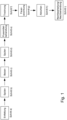
- FIG. 1 The process flow diagram shown schematically shows the successive process stages or process steps a) to i), whereby the process steps b), d), f), h) and i), in particular the process steps h) and i), are optional.
- the process sequence is as follows, wherein the process used according to the invention comprises the following steps successively in this order: degreasing (step a)), rinsing (step b), optional), pickling (step c)), rinsing (step d), optional), flux bath treatment (step e)), drying (step f), optional), hot-dip galvanizing (step g)), cooling (step h), optional) and post-processing or post-treatment (step i), optional).
- FIG. 2 The system used according to the invention with the individual devices (A) to (I) is shown schematically, wherein the devices (B), (D), (F), (H) and (I), in particular the devices (H) and (I), are optional.
- the diagram of the plant used according to the invention shown in the drawing comprises the following devices in the following sequence: degreasing device (A), optionally rinsing device (B), pickling device (C), optionally rinsing device (D), flux treatment device (E), optionally drying device (F), hot-dip galvanizing device (G), if necessary, cooling device (H) and, if necessary, post-processing or post-treatment device (I).
- ad b The sheet metal is completely coated with salts by immersing it in the flux solution. After the drying step, the surface of the component is already slightly dry. To check this, the sheets are weighed after pickling and drying. Compared to variant a), it can be seen that the flux film weighs 2.5% less, which is due to a lower residual moisture content as a result of faster drying. After galvanizing, a homogeneous zinc layer is formed without any defects.
- Example series 1 is repeated, but with a different composition of the galvanizing bath.
- Example series 1 to 5 are repeated, but with a different flux composition (use of 0.005 wt.% or 50 ppm AgCl instead of AlCl 3 ).
- Example series 1 to 5 are repeated, but with a different flux composition (using a combination of 0.0025 wt.% or 25 ppm AgCl and 0.0025 wt.% or 25 ppm AlCl 3 instead of AlCl 3 alone).
- Example series 1 to 15 are repeated, but with different flux composition (complete omission of AlCl 3 and AgCl).
- Total salt content 200 to 700 g/l, typically 450 to 550 g/l pH in the range of 25 to 5
- For AI 4.2 to 6.2%: typically 2.5 to 3.5
- For AI 4.2 to 6.2%: typically 50 to 70°C
- For AI up to 1,000 ppm typically 35 to 60°C wetting agent content 0.2 to 5% Solution with a proportion of propanol and/or ethanol of 0.2 to 72%
- For AI 4.2 to 6.2%: typically 5 to 20%
Landscapes
- Chemical & Material Sciences (AREA)
- Chemical Kinetics & Catalysis (AREA)
- Engineering & Computer Science (AREA)
- Materials Engineering (AREA)
- Mechanical Engineering (AREA)
- Metallurgy (AREA)
- Organic Chemistry (AREA)
- Coating With Molten Metal (AREA)
Applications Claiming Priority (4)
| Application Number | Priority Date | Filing Date | Title |
|---|---|---|---|
| DE102016007107 | 2016-06-13 | ||
| DE102016111725.0A DE102016111725A1 (de) | 2016-06-13 | 2016-06-27 | Verfahren und Flussmittel für die Feuerverzinkung |
| PCT/EP2017/055798 WO2017215796A1 (de) | 2016-06-13 | 2017-03-13 | Verfahren und flussmittel für die feuerverzinkung |
| EP17710526.9A EP3445889B1 (de) | 2016-06-13 | 2017-03-13 | Verfahren und flussmittel für die feuerverzinkung |
Related Parent Applications (2)
| Application Number | Title | Priority Date | Filing Date |
|---|---|---|---|
| EP17710526.9A Division EP3445889B1 (de) | 2016-06-13 | 2017-03-13 | Verfahren und flussmittel für die feuerverzinkung |
| EP17710526.9A Division-Into EP3445889B1 (de) | 2016-06-13 | 2017-03-13 | Verfahren und flussmittel für die feuerverzinkung |
Publications (3)
| Publication Number | Publication Date |
|---|---|
| EP3663429A1 EP3663429A1 (de) | 2020-06-10 |
| EP3663429B1 true EP3663429B1 (de) | 2024-10-16 |
| EP3663429C0 EP3663429C0 (de) | 2024-10-16 |
Family
ID=60419657
Family Applications (2)
| Application Number | Title | Priority Date | Filing Date |
|---|---|---|---|
| EP20151616.8A Active EP3663429B1 (de) | 2016-06-13 | 2017-03-13 | Anlage für die feuerverzinkung |
| EP17710526.9A Active EP3445889B1 (de) | 2016-06-13 | 2017-03-13 | Verfahren und flussmittel für die feuerverzinkung |
Family Applications After (1)
| Application Number | Title | Priority Date | Filing Date |
|---|---|---|---|
| EP17710526.9A Active EP3445889B1 (de) | 2016-06-13 | 2017-03-13 | Verfahren und flussmittel für die feuerverzinkung |
Country Status (14)
| Country | Link |
|---|---|
| US (1) | US11499216B2 (pl) |
| EP (2) | EP3663429B1 (pl) |
| JP (1) | JP6815494B2 (pl) |
| CN (1) | CN109477196B (pl) |
| BR (1) | BR112018075934B1 (pl) |
| CA (1) | CA3026326C (pl) |
| DE (1) | DE102016111725A1 (pl) |
| ES (2) | ES2818732T3 (pl) |
| HU (2) | HUE052348T2 (pl) |
| MA (1) | MA49780A (pl) |
| MX (1) | MX2018015470A (pl) |
| PL (2) | PL3663429T3 (pl) |
| SI (1) | SI3445889T1 (pl) |
| WO (1) | WO2017215796A1 (pl) |
Families Citing this family (14)
| Publication number | Priority date | Publication date | Assignee | Title |
|---|---|---|---|---|
| CN107090571B (zh) * | 2017-06-18 | 2018-05-25 | 荆门宁杰机电技术服务有限公司 | 一种焊管的外镀锌装置 |
| EP3778980A4 (en) | 2018-03-28 | 2021-02-17 | JFE Steel Corporation | HIGH STRENGTH ALLOY HOT GALVANIZED STEEL SHEET AND MANUFACTURING METHOD FOR IT |
| DE102020106543A1 (de) | 2020-03-11 | 2021-09-16 | Bayerische Motoren Werke Aktiengesellschaft | Verfahren zum Verzinken eines Bauteils, insbesondere für ein Kraftfahrzeug, sowie Bauteil für ein Kraftfahrzeug |
| CN112430794A (zh) * | 2020-10-31 | 2021-03-02 | 张家港扬子江冷轧板有限公司 | 一种提高镀锡板表面耐蚀性的自软熔装置及方法 |
| CN114182138B (zh) | 2021-12-14 | 2023-01-03 | 西安交通大学 | 一种生物可降解Zn-Mg-Bi锌合金及其制备方法 |
| DE102022100555A1 (de) | 2022-01-11 | 2023-07-13 | Seppeler Holding Und Verwaltungs Gmbh & Co. Kg | Verfahren zur verbesserten Verzinkung von Bauteilen |
| CN114717500B (zh) * | 2022-03-30 | 2023-12-01 | 青岛靓塔钢结构有限公司 | 一种镀锌单管塔加工工艺 |
| BE1030796B1 (nl) | 2022-08-22 | 2024-03-18 | Balak Coatings Nv | Werkwijze voor het voorbehandelen van een te verzinken hekwerkpaneel en voorbehandeld hekwerkpaneel |
| CN116219344B (zh) * | 2023-01-15 | 2024-02-06 | 宁波市鄞州鑫旺热镀锌有限公司 | 一种铁基铸件的热镀锌工艺 |
| DE102023119937A1 (de) | 2023-07-27 | 2025-01-30 | Fontaine Holdings Nv | Verfahren zur Feuerverzinkung von Bauteilen |
| DE102023121687B4 (de) | 2023-07-27 | 2026-03-12 | Fontaine Holdings Nv | Verfahren zur Feuerverzinkung von Bauteilen, Anlage und Verwendung |
| EP4682292A3 (de) * | 2023-07-27 | 2026-02-18 | Fontaine Holdings NV | Verfahren zur feuerverzinkung von bauteilen |
| KR102816038B1 (ko) * | 2023-09-15 | 2025-06-04 | 한국생산기술연구원 | 도금층 두께 조절이 가능한 Zn-Al-Mg계 용융 도금 강재의 제조방법 |
| DE102025108127B3 (de) * | 2025-01-29 | 2026-03-12 | Fontaine Holdings Nv | Verfahren und Anlage zum Betreiben eines unter Verwendung einer Metallschmelze durchgeführten industriellen Produktionsprozesses sowie Verwendung der Anlage |
Citations (2)
| Publication number | Priority date | Publication date | Assignee | Title |
|---|---|---|---|---|
| DE2317600B2 (de) * | 1973-04-07 | 1975-01-30 | Basf Ag, 6700 Ludwigshafen | Wässerige Flußmittellösungen für die Feuerverzlnkung |
| EP1694880B1 (en) * | 2003-12-09 | 2007-06-13 | Umicore | Heat transfer limiting flux and its use in galvanising steel |
Family Cites Families (16)
| Publication number | Priority date | Publication date | Assignee | Title |
|---|---|---|---|---|
| DE2417791C2 (de) * | 1974-04-11 | 1976-04-01 | Basf Ag, 6700 Ludwigshafen | Flußmittel für die Feuerverzinkung -Verzinnung und -verbleiuhg |
| US4496612A (en) * | 1982-04-06 | 1985-01-29 | E. I. Du Pont De Nemours And Company | Aqueous flux for hot dip metalizing process |
| LU86339A1 (fr) * | 1986-03-04 | 1987-11-11 | Foridienne Chimie N V | Compositions de flux sans fluorures pour la galvanisation a chaud dans des bains de zinc aluminies |
| JP3047936B2 (ja) * | 1991-10-22 | 2000-06-05 | 住友金属鉱山株式会社 | 溶融亜鉛めっき用フラックス |
| WO1995004607A1 (en) * | 1993-08-05 | 1995-02-16 | Ferro Technologies, Inc. | Lead-free galvanizing technique |
| US6200636B1 (en) * | 1998-08-19 | 2001-03-13 | The University Of Cincinnati | Fluxing process for galvanization of steel |
| EP1209245A1 (en) | 2000-11-23 | 2002-05-29 | Galvapower Group N.V. | Flux and its use in hot dip galvanization process |
| ES2425172T3 (es) * | 2005-12-20 | 2013-10-11 | Teck Metals Ltd. | Fundente y procedimiento de galvanizado por inmersión en caliente |
| GB2507310B (en) * | 2012-10-25 | 2018-08-29 | Fontaine Holdings Nv | Flux compositions for hot dip galvanization |
| GB2507309A (en) | 2012-10-25 | 2014-04-30 | Fontaine Holdings Nv | Continuous single dip galvanisation process |
| CN102994925B (zh) * | 2012-12-07 | 2014-05-14 | 国家电网公司 | 一种环保型锌铝合金助镀剂 |
| JP5884200B2 (ja) * | 2013-07-31 | 2016-03-15 | Jfeスチール株式会社 | 溶融亜鉛めっき用フラックスおよび溶融亜鉛めっき用フラックス浴ならびに溶融亜鉛めっき鋼材の製造方法 |
| JP5871035B2 (ja) * | 2013-07-31 | 2016-03-01 | Jfeスチール株式会社 | 溶融亜鉛めっき用フラックスおよび溶融亜鉛めっき用フラックス浴ならびに溶融亜鉛めっき鋼材の製造方法 |
| CN105483591B (zh) * | 2015-12-23 | 2018-12-07 | 常州大学 | 热浸镀用Zn-Al-Si-Ni合金镀层及热浸镀方法 |
| CN105648377B (zh) * | 2016-01-21 | 2017-12-29 | 国网山东省电力公司电力科学研究院 | 一种长时效、可重复使用的热浸镀锌铝镁合金助镀剂 |
| CN106244963B (zh) * | 2016-08-16 | 2018-09-14 | 长安大学 | 一种热镀锌助镀剂及方法 |
-
2016
- 2016-06-27 DE DE102016111725.0A patent/DE102016111725A1/de active Pending
-
2017
- 2017-03-13 CA CA3026326A patent/CA3026326C/en active Active
- 2017-03-13 CN CN201780036941.2A patent/CN109477196B/zh active Active
- 2017-03-13 HU HUE17710526A patent/HUE052348T2/hu unknown
- 2017-03-13 PL PL20151616.8T patent/PL3663429T3/pl unknown
- 2017-03-13 BR BR112018075934-1A patent/BR112018075934B1/pt active IP Right Grant
- 2017-03-13 EP EP20151616.8A patent/EP3663429B1/de active Active
- 2017-03-13 HU HUE20151616A patent/HUE069547T2/hu unknown
- 2017-03-13 MA MA049780A patent/MA49780A/fr unknown
- 2017-03-13 EP EP17710526.9A patent/EP3445889B1/de active Active
- 2017-03-13 WO PCT/EP2017/055798 patent/WO2017215796A1/de not_active Ceased
- 2017-03-13 PL PL17710526T patent/PL3445889T3/pl unknown
- 2017-03-13 ES ES17710526T patent/ES2818732T3/es active Active
- 2017-03-13 MX MX2018015470A patent/MX2018015470A/es unknown
- 2017-03-13 SI SI201730480T patent/SI3445889T1/sl unknown
- 2017-03-13 US US16/309,631 patent/US11499216B2/en active Active
- 2017-03-13 JP JP2019517140A patent/JP6815494B2/ja active Active
- 2017-03-13 ES ES20151616T patent/ES3001448T3/es active Active
Patent Citations (2)
| Publication number | Priority date | Publication date | Assignee | Title |
|---|---|---|---|---|
| DE2317600B2 (de) * | 1973-04-07 | 1975-01-30 | Basf Ag, 6700 Ludwigshafen | Wässerige Flußmittellösungen für die Feuerverzlnkung |
| EP1694880B1 (en) * | 2003-12-09 | 2007-06-13 | Umicore | Heat transfer limiting flux and its use in galvanising steel |
Also Published As
| Publication number | Publication date |
|---|---|
| BR112018075934B1 (pt) | 2023-02-14 |
| MX2018015470A (es) | 2019-10-15 |
| CN109477196B (zh) | 2021-02-19 |
| EP3445889A1 (de) | 2019-02-27 |
| WO2017215796A1 (de) | 2017-12-21 |
| US20190144983A1 (en) | 2019-05-16 |
| JP2019518142A (ja) | 2019-06-27 |
| EP3663429A1 (de) | 2020-06-10 |
| US11499216B2 (en) | 2022-11-15 |
| HUE052348T2 (hu) | 2021-04-28 |
| CN109477196A (zh) | 2019-03-15 |
| CA3026326C (en) | 2020-11-10 |
| DE102016111725A1 (de) | 2017-12-14 |
| JP6815494B2 (ja) | 2021-01-20 |
| PL3663429T3 (pl) | 2025-03-24 |
| CA3026326A1 (en) | 2017-12-21 |
| SI3445889T1 (sl) | 2021-01-29 |
| MA49780A (fr) | 2021-04-07 |
| BR112018075934A2 (pt) | 2019-04-09 |
| EP3445889B1 (de) | 2020-07-29 |
| PL3445889T3 (pl) | 2021-01-11 |
| HUE069547T2 (hu) | 2025-03-28 |
| EP3663429C0 (de) | 2024-10-16 |
| ES2818732T3 (es) | 2021-04-13 |
| ES3001448T3 (en) | 2025-03-05 |
Similar Documents
| Publication | Publication Date | Title |
|---|---|---|
| EP3663429B1 (de) | Anlage für die feuerverzinkung | |
| DE60124767T2 (de) | Flussmittel und verfahren zur feuerverzinkung | |
| EP3400318B1 (de) | Anlage zur feuerverzinkung, feuerverzinkungsverfahren und verwendung derselben | |
| EP3411510B1 (de) | Feuerverzinkungsanlage sowie feuerverzinkungsverfahren | |
| EP3400317B1 (de) | Anlage zur feuerverzinkung und feuerverzinkungsverfahren für die grossserienproduktion | |
| EP2290133A1 (de) | Verfahren zum Herstellen eines mit einem metallischen, vor Korrosion schützenden Überzug versehenen Stahlbauteils und Stahlbauteil | |
| EP3058116B1 (de) | Verfahren zur vorbereitung von metallischen formkörpern für die kaltumformung | |
| EP3880860B1 (de) | Verfahren zur verzinkung, insbesondere feuerverzinkung, von eisen- und stahlerzeugnissen | |
| EP4363632A2 (de) | Verfahren für den sequenziellen aufbau einer konversionsschicht auf bauteilen umfassend stahloberflächen | |
| EP2088223A1 (de) | Phosphatiertes Stahlblech sowie Verfahren zur Herstellung eines solchen Blechs | |
| EP3755825A1 (de) | Verfahren zur selektiven phosphatierung einer verbundmetallkonstruktion | |
| DE69129180T2 (de) | Flussmittel zur Verwendung in einem Trockenverfahren zur Flussmittelbehandlung einer Beschichtung aus geschmolzenem Metall und Verfahren zur Herstellung von mit geschmolzenem Metall beschichtetem Stahl. | |
| EP3363576B1 (de) | Verfahren und anlage zur kennzeichnung und/oder markierung feuerverzinkter bauteile und damit hergestellte bauteile | |
| EP3592878B1 (de) | Feuerverzinkungsverfahren, trage- und/oder haltemittel für die feuerverzinkung, sowie beschichtungsverfahren des trage- und/oder haltemittels | |
| DE102023121687B4 (de) | Verfahren zur Feuerverzinkung von Bauteilen, Anlage und Verwendung | |
| DE102023119937A1 (de) | Verfahren zur Feuerverzinkung von Bauteilen | |
| EP1350865A2 (de) | Verzinktes und phosphatiertes Blech sowie Verfahren zur Herstellung eines solchen Blechs | |
| EP4676679A1 (de) | Verfahren zur feuerverzinkung von bauteilen | |
| EP4563721A1 (de) | Verfahren für die korrosionsschützende vorbehandlung von bauteilen umfassend oberflächen von zink-magnesium-schmelztauchveredeltem stahl | |
| WO2024227530A1 (de) | Verfahren zum feuerverzinken und feuerverzinktes bauteil |
Legal Events
| Date | Code | Title | Description |
|---|---|---|---|
| PUAI | Public reference made under article 153(3) epc to a published international application that has entered the european phase |
Free format text: ORIGINAL CODE: 0009012 |
|
| STAA | Information on the status of an ep patent application or granted ep patent |
Free format text: STATUS: REQUEST FOR EXAMINATION WAS MADE |
|
| 17P | Request for examination filed |
Effective date: 20200331 |
|
| AC | Divisional application: reference to earlier application |
Ref document number: 3445889 Country of ref document: EP Kind code of ref document: P |
|
| AK | Designated contracting states |
Kind code of ref document: A1 Designated state(s): AL AT BE BG CH CY CZ DE DK EE ES FI FR GB GR HR HU IE IS IT LI LT LU LV MC MK MT NL NO PL PT RO RS SE SI SK SM TR |
|
| AX | Request for extension of the european patent |
Extension state: BA ME |
|
| STAA | Information on the status of an ep patent application or granted ep patent |
Free format text: STATUS: EXAMINATION IS IN PROGRESS |
|
| 17Q | First examination report despatched |
Effective date: 20210303 |
|
| RIC1 | Information provided on ipc code assigned before grant |
Ipc: C23C 2/30 20060101ALI20240708BHEP Ipc: C23C 2/26 20060101ALI20240708BHEP Ipc: C23C 2/06 20060101ALI20240708BHEP Ipc: C23C 2/00 20060101ALI20240708BHEP Ipc: C23C 2/02 20060101AFI20240708BHEP |
|
| GRAP | Despatch of communication of intention to grant a patent |
Free format text: ORIGINAL CODE: EPIDOSNIGR1 |
|
| STAA | Information on the status of an ep patent application or granted ep patent |
Free format text: STATUS: GRANT OF PATENT IS INTENDED |
|
| GRAS | Grant fee paid |
Free format text: ORIGINAL CODE: EPIDOSNIGR3 |
|
| GRAA | (expected) grant |
Free format text: ORIGINAL CODE: 0009210 |
|
| STAA | Information on the status of an ep patent application or granted ep patent |
Free format text: STATUS: THE PATENT HAS BEEN GRANTED |
|
| INTG | Intention to grant announced |
Effective date: 20240816 |
|
| AC | Divisional application: reference to earlier application |
Ref document number: 3445889 Country of ref document: EP Kind code of ref document: P |
|
| AK | Designated contracting states |
Kind code of ref document: B1 Designated state(s): AL AT BE BG CH CY CZ DE DK EE ES FI FR GB GR HR HU IE IS IT LI LT LU LV MC MK MT NL NO PL PT RO RS SE SI SK SM TR |
|
| REG | Reference to a national code |
Ref country code: GB Ref legal event code: FG4D Free format text: NOT ENGLISH |
|
| REG | Reference to a national code |
Ref country code: DE Ref legal event code: R096 Ref document number: 502017016500 Country of ref document: DE Ref country code: CH Ref legal event code: EP |
|
| REG | Reference to a national code |
Ref country code: IE Ref legal event code: FG4D Free format text: LANGUAGE OF EP DOCUMENT: GERMAN |
|
| U01 | Request for unitary effect filed |
Effective date: 20241016 |
|
| U07 | Unitary effect registered |
Designated state(s): AT BE BG DE DK EE FI FR IT LT LU LV MT NL PT RO SE SI Effective date: 20241024 |
|
| REG | Reference to a national code |
Ref country code: SK Ref legal event code: T3 Ref document number: E 45505 Country of ref document: SK |
|
| REG | Reference to a national code |
Ref country code: HU Ref legal event code: AG4A Ref document number: E069547 Country of ref document: HU |
|
| PG25 | Lapsed in a contracting state [announced via postgrant information from national office to epo] |
Ref country code: HR Free format text: LAPSE BECAUSE OF FAILURE TO SUBMIT A TRANSLATION OF THE DESCRIPTION OR TO PAY THE FEE WITHIN THE PRESCRIBED TIME-LIMIT Effective date: 20241016 Ref country code: IS Free format text: LAPSE BECAUSE OF FAILURE TO SUBMIT A TRANSLATION OF THE DESCRIPTION OR TO PAY THE FEE WITHIN THE PRESCRIBED TIME-LIMIT Effective date: 20250216 |
|
| PGFP | Annual fee paid to national office [announced via postgrant information from national office to epo] |
Ref country code: HU Payment date: 20250320 Year of fee payment: 9 |
|
| PG25 | Lapsed in a contracting state [announced via postgrant information from national office to epo] |
Ref country code: NO Free format text: LAPSE BECAUSE OF FAILURE TO SUBMIT A TRANSLATION OF THE DESCRIPTION OR TO PAY THE FEE WITHIN THE PRESCRIBED TIME-LIMIT Effective date: 20250116 |
|
| PG25 | Lapsed in a contracting state [announced via postgrant information from national office to epo] |
Ref country code: GR Free format text: LAPSE BECAUSE OF FAILURE TO SUBMIT A TRANSLATION OF THE DESCRIPTION OR TO PAY THE FEE WITHIN THE PRESCRIBED TIME-LIMIT Effective date: 20250117 |
|
| PGFP | Annual fee paid to national office [announced via postgrant information from national office to epo] |
Ref country code: PL Payment date: 20250303 Year of fee payment: 9 Ref country code: CZ Payment date: 20250306 Year of fee payment: 9 |
|
| PGFP | Annual fee paid to national office [announced via postgrant information from national office to epo] |
Ref country code: SK Payment date: 20250304 Year of fee payment: 9 Ref country code: GB Payment date: 20250324 Year of fee payment: 9 |
|
| PG25 | Lapsed in a contracting state [announced via postgrant information from national office to epo] |
Ref country code: RS Free format text: LAPSE BECAUSE OF FAILURE TO SUBMIT A TRANSLATION OF THE DESCRIPTION OR TO PAY THE FEE WITHIN THE PRESCRIBED TIME-LIMIT Effective date: 20250116 |
|
| PGFP | Annual fee paid to national office [announced via postgrant information from national office to epo] |
Ref country code: TR Payment date: 20250304 Year of fee payment: 9 |
|
| U20 | Renewal fee for the european patent with unitary effect paid |
Year of fee payment: 9 Effective date: 20250328 |
|
| PG25 | Lapsed in a contracting state [announced via postgrant information from national office to epo] |
Ref country code: SM Free format text: LAPSE BECAUSE OF FAILURE TO SUBMIT A TRANSLATION OF THE DESCRIPTION OR TO PAY THE FEE WITHIN THE PRESCRIBED TIME-LIMIT Effective date: 20241016 |
|
| PGFP | Annual fee paid to national office [announced via postgrant information from national office to epo] |
Ref country code: ES Payment date: 20250429 Year of fee payment: 9 |
|
| VS25 | Lapsed in a validation state [announced via postgrant information from nat. office to epo] |
Ref country code: MD Free format text: LAPSE BECAUSE OF FAILURE TO SUBMIT A TRANSLATION OF THE DESCRIPTION OR TO PAY THE FEE WITHIN THE PRESCRIBED TIME-LIMIT Effective date: 20241016 |
|
| PGFP | Annual fee paid to national office [announced via postgrant information from national office to epo] |
Ref country code: CH Payment date: 20250401 Year of fee payment: 9 |
|
| PLBE | No opposition filed within time limit |
Free format text: ORIGINAL CODE: 0009261 |
|
| STAA | Information on the status of an ep patent application or granted ep patent |
Free format text: STATUS: NO OPPOSITION FILED WITHIN TIME LIMIT |
|
| 26N | No opposition filed |
Effective date: 20250717 |
|
| PG25 | Lapsed in a contracting state [announced via postgrant information from national office to epo] |
Ref country code: MC Free format text: LAPSE BECAUSE OF FAILURE TO SUBMIT A TRANSLATION OF THE DESCRIPTION OR TO PAY THE FEE WITHIN THE PRESCRIBED TIME-LIMIT Effective date: 20241016 |
|
| PG25 | Lapsed in a contracting state [announced via postgrant information from national office to epo] |
Ref country code: IE Free format text: LAPSE BECAUSE OF NON-PAYMENT OF DUE FEES Effective date: 20250313 |